EP3936229A1 - Catalyst material - Google Patents
Catalyst material Download PDFInfo
- Publication number
- EP3936229A1 EP3936229A1 EP20782718.9A EP20782718A EP3936229A1 EP 3936229 A1 EP3936229 A1 EP 3936229A1 EP 20782718 A EP20782718 A EP 20782718A EP 3936229 A1 EP3936229 A1 EP 3936229A1
- Authority
- EP
- European Patent Office
- Prior art keywords
- catalyst
- carrier
- alumina
- palladium
- exhaust gas
- Prior art date
- Legal status (The legal status is an assumption and is not a legal conclusion. Google has not performed a legal analysis and makes no representation as to the accuracy of the status listed.)
- Withdrawn
Links
Images




Classifications
-
- B—PERFORMING OPERATIONS; TRANSPORTING
- B01—PHYSICAL OR CHEMICAL PROCESSES OR APPARATUS IN GENERAL
- B01J—CHEMICAL OR PHYSICAL PROCESSES, e.g. CATALYSIS OR COLLOID CHEMISTRY; THEIR RELEVANT APPARATUS
- B01J35/00—Catalysts, in general, characterised by their form or physical properties
- B01J35/60—Catalysts, in general, characterised by their form or physical properties characterised by their surface properties or porosity
- B01J35/61—Surface area
- B01J35/613—10-100 m2/g
-
- B—PERFORMING OPERATIONS; TRANSPORTING
- B01—PHYSICAL OR CHEMICAL PROCESSES OR APPARATUS IN GENERAL
- B01J—CHEMICAL OR PHYSICAL PROCESSES, e.g. CATALYSIS OR COLLOID CHEMISTRY; THEIR RELEVANT APPARATUS
- B01J23/00—Catalysts comprising metals or metal oxides or hydroxides, not provided for in group B01J21/00
- B01J23/38—Catalysts comprising metals or metal oxides or hydroxides, not provided for in group B01J21/00 of noble metals
- B01J23/40—Catalysts comprising metals or metal oxides or hydroxides, not provided for in group B01J21/00 of noble metals of the platinum group metals
- B01J23/44—Palladium
-
- B—PERFORMING OPERATIONS; TRANSPORTING
- B01—PHYSICAL OR CHEMICAL PROCESSES OR APPARATUS IN GENERAL
- B01D—SEPARATION
- B01D53/00—Separation of gases or vapours; Recovering vapours of volatile solvents from gases; Chemical or biological purification of waste gases, e.g. engine exhaust gases, smoke, fumes, flue gases, aerosols
- B01D53/34—Chemical or biological purification of waste gases
- B01D53/92—Chemical or biological purification of waste gases of engine exhaust gases
- B01D53/94—Chemical or biological purification of waste gases of engine exhaust gases by catalytic processes
-
- B—PERFORMING OPERATIONS; TRANSPORTING
- B01—PHYSICAL OR CHEMICAL PROCESSES OR APPARATUS IN GENERAL
- B01D—SEPARATION
- B01D53/00—Separation of gases or vapours; Recovering vapours of volatile solvents from gases; Chemical or biological purification of waste gases, e.g. engine exhaust gases, smoke, fumes, flue gases, aerosols
- B01D53/34—Chemical or biological purification of waste gases
- B01D53/92—Chemical or biological purification of waste gases of engine exhaust gases
- B01D53/94—Chemical or biological purification of waste gases of engine exhaust gases by catalytic processes
- B01D53/944—Simultaneously removing carbon monoxide, hydrocarbons or carbon making use of oxidation catalysts
-
- B—PERFORMING OPERATIONS; TRANSPORTING
- B01—PHYSICAL OR CHEMICAL PROCESSES OR APPARATUS IN GENERAL
- B01J—CHEMICAL OR PHYSICAL PROCESSES, e.g. CATALYSIS OR COLLOID CHEMISTRY; THEIR RELEVANT APPARATUS
- B01J21/00—Catalysts comprising the elements, oxides, or hydroxides of magnesium, boron, aluminium, carbon, silicon, titanium, zirconium, or hafnium
- B01J21/02—Boron or aluminium; Oxides or hydroxides thereof
- B01J21/04—Alumina
-
- B—PERFORMING OPERATIONS; TRANSPORTING
- B01—PHYSICAL OR CHEMICAL PROCESSES OR APPARATUS IN GENERAL
- B01J—CHEMICAL OR PHYSICAL PROCESSES, e.g. CATALYSIS OR COLLOID CHEMISTRY; THEIR RELEVANT APPARATUS
- B01J35/00—Catalysts, in general, characterised by their form or physical properties
- B01J35/30—Catalysts, in general, characterised by their form or physical properties characterised by their physical properties
- B01J35/391—Physical properties of the active metal ingredient
- B01J35/393—Metal or metal oxide crystallite size
-
- B—PERFORMING OPERATIONS; TRANSPORTING
- B01—PHYSICAL OR CHEMICAL PROCESSES OR APPARATUS IN GENERAL
- B01J—CHEMICAL OR PHYSICAL PROCESSES, e.g. CATALYSIS OR COLLOID CHEMISTRY; THEIR RELEVANT APPARATUS
- B01J35/00—Catalysts, in general, characterised by their form or physical properties
- B01J35/40—Catalysts, in general, characterised by their form or physical properties characterised by dimensions, e.g. grain size
- B01J35/45—Nanoparticles
-
- B—PERFORMING OPERATIONS; TRANSPORTING
- B01—PHYSICAL OR CHEMICAL PROCESSES OR APPARATUS IN GENERAL
- B01J—CHEMICAL OR PHYSICAL PROCESSES, e.g. CATALYSIS OR COLLOID CHEMISTRY; THEIR RELEVANT APPARATUS
- B01J35/00—Catalysts, in general, characterised by their form or physical properties
- B01J35/60—Catalysts, in general, characterised by their form or physical properties characterised by their surface properties or porosity
- B01J35/61—Surface area
- B01J35/615—100-500 m2/g
-
- F—MECHANICAL ENGINEERING; LIGHTING; HEATING; WEAPONS; BLASTING
- F01—MACHINES OR ENGINES IN GENERAL; ENGINE PLANTS IN GENERAL; STEAM ENGINES
- F01N—GAS-FLOW SILENCERS OR EXHAUST APPARATUS FOR MACHINES OR ENGINES IN GENERAL; GAS-FLOW SILENCERS OR EXHAUST APPARATUS FOR INTERNAL-COMBUSTION ENGINES
- F01N3/00—Exhaust or silencing apparatus having means for purifying, rendering innocuous, or otherwise treating exhaust
- F01N3/08—Exhaust or silencing apparatus having means for purifying, rendering innocuous, or otherwise treating exhaust for rendering innocuous
-
- F—MECHANICAL ENGINEERING; LIGHTING; HEATING; WEAPONS; BLASTING
- F01—MACHINES OR ENGINES IN GENERAL; ENGINE PLANTS IN GENERAL; STEAM ENGINES
- F01N—GAS-FLOW SILENCERS OR EXHAUST APPARATUS FOR MACHINES OR ENGINES IN GENERAL; GAS-FLOW SILENCERS OR EXHAUST APPARATUS FOR INTERNAL-COMBUSTION ENGINES
- F01N3/00—Exhaust or silencing apparatus having means for purifying, rendering innocuous, or otherwise treating exhaust
- F01N3/08—Exhaust or silencing apparatus having means for purifying, rendering innocuous, or otherwise treating exhaust for rendering innocuous
- F01N3/10—Exhaust or silencing apparatus having means for purifying, rendering innocuous, or otherwise treating exhaust for rendering innocuous by thermal or catalytic conversion of noxious components of exhaust
- F01N3/103—Oxidation catalysts for HC and CO only
-
- F—MECHANICAL ENGINEERING; LIGHTING; HEATING; WEAPONS; BLASTING
- F01—MACHINES OR ENGINES IN GENERAL; ENGINE PLANTS IN GENERAL; STEAM ENGINES
- F01N—GAS-FLOW SILENCERS OR EXHAUST APPARATUS FOR MACHINES OR ENGINES IN GENERAL; GAS-FLOW SILENCERS OR EXHAUST APPARATUS FOR INTERNAL-COMBUSTION ENGINES
- F01N3/00—Exhaust or silencing apparatus having means for purifying, rendering innocuous, or otherwise treating exhaust
- F01N3/08—Exhaust or silencing apparatus having means for purifying, rendering innocuous, or otherwise treating exhaust for rendering innocuous
- F01N3/10—Exhaust or silencing apparatus having means for purifying, rendering innocuous, or otherwise treating exhaust for rendering innocuous by thermal or catalytic conversion of noxious components of exhaust
- F01N3/24—Exhaust or silencing apparatus having means for purifying, rendering innocuous, or otherwise treating exhaust for rendering innocuous by thermal or catalytic conversion of noxious components of exhaust characterised by constructional aspects of converting apparatus
- F01N3/28—Construction of catalytic reactors
- F01N3/2803—Construction of catalytic reactors characterised by structure, by material or by manufacturing of catalyst support
- F01N3/2825—Ceramics
-
- B—PERFORMING OPERATIONS; TRANSPORTING
- B01—PHYSICAL OR CHEMICAL PROCESSES OR APPARATUS IN GENERAL
- B01D—SEPARATION
- B01D2255/00—Catalysts
- B01D2255/10—Noble metals or compounds thereof
- B01D2255/102—Platinum group metals
- B01D2255/1023—Palladium
-
- B—PERFORMING OPERATIONS; TRANSPORTING
- B01—PHYSICAL OR CHEMICAL PROCESSES OR APPARATUS IN GENERAL
- B01D—SEPARATION
- B01D2255/00—Catalysts
- B01D2255/90—Physical characteristics of catalysts
- B01D2255/92—Dimensions
-
- B—PERFORMING OPERATIONS; TRANSPORTING
- B01—PHYSICAL OR CHEMICAL PROCESSES OR APPARATUS IN GENERAL
- B01D—SEPARATION
- B01D2255/00—Catalysts
- B01D2255/90—Physical characteristics of catalysts
- B01D2255/92—Dimensions
- B01D2255/9207—Specific surface
-
- B—PERFORMING OPERATIONS; TRANSPORTING
- B01—PHYSICAL OR CHEMICAL PROCESSES OR APPARATUS IN GENERAL
- B01D—SEPARATION
- B01D2257/00—Components to be removed
- B01D2257/70—Organic compounds not provided for in groups B01D2257/00 - B01D2257/602
- B01D2257/702—Hydrocarbons
- B01D2257/7022—Aliphatic hydrocarbons
- B01D2257/7025—Methane
-
- B—PERFORMING OPERATIONS; TRANSPORTING
- B01—PHYSICAL OR CHEMICAL PROCESSES OR APPARATUS IN GENERAL
- B01J—CHEMICAL OR PHYSICAL PROCESSES, e.g. CATALYSIS OR COLLOID CHEMISTRY; THEIR RELEVANT APPARATUS
- B01J2235/00—Indexing scheme associated with group B01J35/00, related to the analysis techniques used to determine the catalysts form or properties
-
- B—PERFORMING OPERATIONS; TRANSPORTING
- B01—PHYSICAL OR CHEMICAL PROCESSES OR APPARATUS IN GENERAL
- B01J—CHEMICAL OR PHYSICAL PROCESSES, e.g. CATALYSIS OR COLLOID CHEMISTRY; THEIR RELEVANT APPARATUS
- B01J2235/00—Indexing scheme associated with group B01J35/00, related to the analysis techniques used to determine the catalysts form or properties
- B01J2235/15—X-ray diffraction
-
- B—PERFORMING OPERATIONS; TRANSPORTING
- B01—PHYSICAL OR CHEMICAL PROCESSES OR APPARATUS IN GENERAL
- B01J—CHEMICAL OR PHYSICAL PROCESSES, e.g. CATALYSIS OR COLLOID CHEMISTRY; THEIR RELEVANT APPARATUS
- B01J2235/00—Indexing scheme associated with group B01J35/00, related to the analysis techniques used to determine the catalysts form or properties
- B01J2235/30—Scanning electron microscopy; Transmission electron microscopy
-
- F—MECHANICAL ENGINEERING; LIGHTING; HEATING; WEAPONS; BLASTING
- F01—MACHINES OR ENGINES IN GENERAL; ENGINE PLANTS IN GENERAL; STEAM ENGINES
- F01N—GAS-FLOW SILENCERS OR EXHAUST APPARATUS FOR MACHINES OR ENGINES IN GENERAL; GAS-FLOW SILENCERS OR EXHAUST APPARATUS FOR INTERNAL-COMBUSTION ENGINES
- F01N2330/00—Structure of catalyst support or particle filter
- F01N2330/06—Ceramic, e.g. monoliths
-
- F—MECHANICAL ENGINEERING; LIGHTING; HEATING; WEAPONS; BLASTING
- F01—MACHINES OR ENGINES IN GENERAL; ENGINE PLANTS IN GENERAL; STEAM ENGINES
- F01N—GAS-FLOW SILENCERS OR EXHAUST APPARATUS FOR MACHINES OR ENGINES IN GENERAL; GAS-FLOW SILENCERS OR EXHAUST APPARATUS FOR INTERNAL-COMBUSTION ENGINES
- F01N2370/00—Selection of materials for exhaust purification
- F01N2370/02—Selection of materials for exhaust purification used in catalytic reactors
-
- F—MECHANICAL ENGINEERING; LIGHTING; HEATING; WEAPONS; BLASTING
- F01—MACHINES OR ENGINES IN GENERAL; ENGINE PLANTS IN GENERAL; STEAM ENGINES
- F01N—GAS-FLOW SILENCERS OR EXHAUST APPARATUS FOR MACHINES OR ENGINES IN GENERAL; GAS-FLOW SILENCERS OR EXHAUST APPARATUS FOR INTERNAL-COMBUSTION ENGINES
- F01N2510/00—Surface coverings
- F01N2510/06—Surface coverings for exhaust purification, e.g. catalytic reaction
- F01N2510/068—Surface coverings for exhaust purification, e.g. catalytic reaction characterised by the distribution of the catalytic coatings
Definitions
- the present invention relates to a catalyst material used for purifying exhaust gas containing methane.
- the present application claims priority from Japanese Patent Application No. 2019-067927 filed on March 29, 2019 , the entire disclosure of which is incorporated by reference herein.
- harmful gaseous components such as hydrocarbon (HC), carbon monoxide (CO), nitrogen oxide (NO x ), or the like, as well as a particulate matter (PM) which is mainly composed of carbon.
- HC hydrocarbon
- CO carbon monoxide
- NO x nitrogen oxide
- PM particulate matter
- HC emitted from gasoline internal combustion engines that use gasoline as fuel are aromatics, olefins, paraffins, or the like that are components easily burned at relatively low temperature
- HC emitted from natural gas internal combustion engines are mostly methane (CH 4 ) that is chemically stable and difficult to decompose at low temperature.
- Known technologies for catalysts used for purifying methane contained in exhaust gas of such natural gas internal combustion engines include, for example, Patent Documents 1 to 5.
- the present invention has been devised and it is therefore an object of the present invention to provide an exhaust gas purification catalyst having an excellent purification performance for purifying chemically stable methane.
- the present invention provides a catalyst material used for purifying methane.
- the catalyst material includes a carrier formed of alumina and a catalyst formed of at least one of palladium and a palladium oxide directly supported by the carrier.
- a specific surface area of the carrier is 20 m 2 /g or more and 90 m 2 /g or less.
- the specific surface area of alumina that is the catalyst carrier is limited to a specific range.
- alumina having the above-described specific surface area each of crystal structures of palladium and a palladium oxide that are crystally grown and supported directly on a surface thereof can be made into a crystal structure in which a specific crystal orientation is high.
- 50% methane purification temperature of palladium and the palladium oxide that are catalysts can be lowered and a methane purification performance of the catalyst material can be increased.
- a proportion of Pd(100) and PdO(101) in crystal planes of the catalyst at a joint surface between the catalyst and the carrier is 20 number% or more. According to the above-described structure, the methane purification performance can be preferably increased more reliably.
- a proportion of 0(001), 0(111), and ⁇ (104) in crystal planes of the carrier at a joint surface between the catalyst and the carrier is 30 number% or more. According to the above-described structure, the proportion of Pd(100) and PdO(101) of the catalyst at the joint surface can be increased, and consequently, a catalyst material having an excellent methane purification performance can be preferably obtained.
- an average particle diameter of the catalyst is 20 nm or less. According to the above-described structure, a contact efficiency of the catalyst with methane gas per unit mass can be preferably increased. Furthermore, it is preferable that the average particle diameter of the catalyst is 10 nm or less because a catalyst activity is further increased due to a sizing effect.
- a supported ratio of the catalyst to a total amount of the carrier and the catalyst is 10 mass% or less.
- the catalyst material disclosed herein can exhibit a high methane purification performance with a smaller catalyst amount. Therefore, in a case where the supported ratio of the catalyst is made 10 mass% or less, particularly, the above-described effects can be preferably exhibited in a clear manner.
- the catalyst material is used for purifying exhaust gas emitted from an internal combustion engine using natural gas as fuel.
- the internal combustion engine uses natural gas as fuel
- 80 mass% or more of HC contained in the exhaust gas can be methane.
- the exhaust gas purification catalyst of the technology disclosed herein preferably exhibits the above-described effects in a case where the exhaust gas purification catalyst is used for purifying the exhaust gas having a high content of methane.
- the catalyst material disclosed herein has an excellent methane purification performance, and for example, the purification rate for methane in gas can be made 50% or more in a lower temperature range.
- This feature is preferable because, when the catalyst material is preferably used for purifying methane contained in exhaust gas at relatively low temperature, for example, during cold start-up of the internal combustion engine, during idling stop control, or the like, advantages thereof can be fully exhibited. Therefore, the catalyst material can be preferably used as a catalyst material in an exhaust gas purification catalyst body for, for example, a natural gas (CNG) engine, a gasoline engine, a diesel engine, or the like.
- CNG natural gas
- the catalyst material can be preferably used in a case where the internal combustion engine is an internal combustion engine of a vehicle (including a hybrid vehicle, a plug-in hybrid vehicle, or the like including a driving power source, in addition to an engine vehicle) with relatively large fluctuations in rotation speed. It is particularly preferable to use the catalyst material as a catalyst material of an exhaust gas purification catalyst body of a CNG engine in which a proportion of methane in HC contained in exhaust gas is high.
- FIG. 1 is a cross-sectional view illustrating a structure of a catalyst material 30 according to one embodiment.
- the catalyst material 30 disclosed herein is a catalyst material used for purifying methane.
- the catalyst material 30 includes a carrier 32 and a catalyst 34 directly supported by the carrier 32. Constituent components of the catalyst material 30 will be described below.
- the carrier 32 that supports the catalyst 34 is formed of alumina.
- alumina there is no particular limitation on a crystal structure of alumina.
- Various polymorphic forms of alumina such as ⁇ -alumina, ⁇ -alumina, ⁇ -alumina, ⁇ -alumina, or the like, are known, and the crystal structure of alumina as the carrier 32 may include one or two or more of the above-described polymorphic forms.
- Alumina other than ⁇ -alumina of a high temperature stable phase is referred to as transition alumina (also referred to as intermediate alumina), generally has ultra-fine primary particles, and has a large specific surface area.
- alumina carrier of a known catalyst for automobiles in general, an intermediate alumina, that is, a ⁇ -alumina having a particularly high specific surface area has been widely used.
- alumina as the carrier 32 preferably has a relatively small specific surface area, that is, a specific surface area of 90 m 2 /g or less (for example, 20 m 2 /g or more and 90 m 2 /g or less).
- alumina As a carrier, generation of the catalyst 34 having a specific crystal orientation on a surface thereof can be promoted, for example, in a method for manufacturing the catalyst material 30 described later, and therefore, use of such alumina as a carrier is preferable.
- the specific surface area of alumina serving as the carrier 32 is appropriately 90 m 2 or less, preferably 85 m 2 /g or less, and may be 80 m 2 /g or less or 75 m 2 /g or less, that is, for example, 60 m 2 /g or less in view of increasing a proportion at which the crystal plane on which the catalyst 34 in a preferable external form can be easily grown is exposed on the surface thereof.
- the specific surface area of alumina serving as the carrier 32 is too small because a proportion of flat surfaces, that is, in other words, the specific crystal planes, in the external form of alumina becomes excessively high and the carried catalyst 34 tends to grow coarsely when the carried catalyst 34 is generated or when the catalyst material is used.
- the specific surface area is, for example, appropriately 15 m 2 /g or more, preferably 20 m 2 /g or more, and may be 25 m 2 /g or more, 30 m 2 /g or more (for example, more than 30 m 2 /g), or 35 m 2 /g or more, that is, for example, 40 m 2 /g or more.
- the carrier 32 has the above-described specific surface area, there is no particular limitation on a shape of the carrier 32.
- the carrier 32 may be formed of powdered alumina and/or porous alumina.
- an average particle diameter of the carrier 32 is, for example, preferably 20 ⁇ m or less, typically 10 ⁇ m or less, or 7 ⁇ m or less, that is, for example, 5 ⁇ m or less.
- the average particle diameter of the carrier 32 may be typically 0.1 ⁇ m or more, that is, for example, 0.5 ⁇ m or more, 1 ⁇ m or more, or 3 ⁇ m or more in view of increasing a heat resistance of the catalyst material 30.
- the average particle diameter of a material that is the catalyst material 30, the carrier 32, or the like and is in a form of powder is cumulative 50% particle diameter (Dso) in a volume-based particle diameter distribution measured by a laser diffraction scattering method.
- the specific surface area of the carrier 32 is a value calculated by a BET method (for example, a BET one-point method), based on an amount of gas absorbed measured by a gas absorption method (a constant capacity adsorption method).
- a BET method for example, a BET one-point method
- an amount of gas absorbed measured by a gas absorption method a constant capacity adsorption method.
- nitrogen (N 2 ) gas can be preferably used.
- the catalyst 34 is formed of at least one of palladium and a palladium oxide.
- the catalyst 34 is supported directly and integrally on a surface of alumina serving as the carrier 32.
- the catalyst 34 is bonded to the surface of the carrier 32 without a binding agent, such as a binder or the like.
- the catalyst 34 is supported on the surface of alumina serving as the carrier through crystal growth directly thereon.
- the catalyst 34 crystally grows on the surface of alumina and, when the crystal plane of alumna serving as the carrier 32 is the above-described specific plane, crystal growth of the catalyst 34 with a certain crystal orientation relationship with the specific plane of alumina tends to be induced.
- Crystal planes of palladium (Pd) and a palladium oxide (PdO) whose growth tends to be induced on the specific plane of alumina are Pd(100) and PdO(101) (which will be hereinafter occasionally referred to as simply "the palladium specific planes").
- Pd tends to grow in a (100) plane orientation on the specific plane of alumina serving as the carrier 32.
- PdO tends to grow in a (101) plane orientation.
- Pd and PdO for example, Pd is easily oxidized into PdO and PdO is easily reduced to Pd by reversible change of an electronic state of Pd due to fluctuations of an atmosphere of exhaust gas.
- a valence number of Pd in a palladium oxide may be a value larger than +2 (for example, a value of about +2 to +3).
- the catalyst material disclosed herein has a structure in which the carrier 32 and the catalyst 34 are plane-oriented at a high proportion, as illustrated in FIG. 1 .
- a proportion of the specific planes of palladium in the crystal planes of the catalyst 34 at a joint surface of the catalyst 34 with the carrier 32 can be 20 number% or more.
- the proportion of the specific planes of palladium at a catalyst-carrier interface of the catalyst material 30 As the proportion increases, for example, 50% methane purification temperature reduces or the like, so that the methane purification performance is increased.
- the proportion of the specific planes of palladium is preferably 20 number% or more, more preferably 25 number% or more, and may be, for example, 30 number% or more, 35 number% or more, 40 number% or more, or the like.
- an upper limit of the proportion of the specific planes of palladium at the catalyst-carrier interface may be substantially 100 number% or less (for example, 100 number%) and may be, for example, 95 number% or less, 90 number% or less, 85 number% or less, 80 number% or less, 70 number% or less, or the like.
- the specific planes of palladium at the catalyst-carrier interface can be induced by the specific planes of alumina.
- a proportion of the specific planes of alumina is preferably large. Accordingly, the proportion of the specific planes of alumina at the interface is preferably 30 number% or more, more preferably 32 number% or more, and may be, for example, 35 number% or more.
- an upper limit of the proportion of the specific planes of palladium at the catalyst-carrier interface there is no particular limitation on an upper limit of the proportion of the specific planes of palladium at the catalyst-carrier interface, and the upper limit may be 100 number% or less (for example, 100 number%) and may be substantially 50 number% or less and 45 number% or less, that is, for example, about 40 number% or less or the like.
- the crystal planes forming the interface between the catalyst 34 and the carrier 32 can be specified by a known method by observation using a transmission electro microscope (TEM).
- TEM transmission electro microscope
- a crystal structure image or a crystal photon image at the interface between the catalyst 34 and the carrier 32 may be obtained and the crystal planes forming the interface may be identified for each of the catalyst 34 and the carrier 32.
- Identification of the crystal planes may be performed based on a known crystal plane spacing (lattice spacing), the crystal planes may be identified using an electron diffraction observation mode of TEM. In this specification, as described in examples below, the crystal planes are identified based on the crystal plane spacing.
- the catalyst 34 may be a particulate catalyst (which will be hereinafter referred to as catalyst particles or the like) having a large specific surface area and, for example, 90 number% or more of the catalyst particles preferably have a particle diameter of about 20 nm or less that exhibits a sizing effect.
- An average particle diameter of the catalyst particles may be, for example, 15 nm or less, more preferably 10 nm or less, and typically 8 nm or less or 7 nm or more.
- the average particle diameter of the catalyst particles is a value (volume sphere equivalent diameter) calculated by a pulse absorption method using carbon monoxide (CO) as an absorption gas.
- the pulse absorption method was performed in accordance with "a metal surface area measuring method using a CO pulse method" by the Reference Catalyst Division, of the Catalysis Society of Japan.
- a supported amount of the catalyst 34 supported there is no particular limitation on a supported amount of the catalyst 34 supported, but when the supported amount of the catalyst 34 supported is too small, a catalyst activity achieved by the catalyst 34 is insufficient, and therefore, it is not preferable that the supported amount of the catalyst 34 is too small.
- a proportion (supported amount) of the catalyst 34 to a total mass of the catalyst material 30 is appropriately 0.001 mass% or more, preferably 0.01 mass% or more, and may be, for example, 0.1 mass% or more.
- the proportion of the catalyst 34 to the total mass of the catalyst material 30 may be, for example, 10 mass% of less, is preferably 8 mass% or less, and typically may be 5 mass% or less.
- the above-described catalyst material 30 can be obtained by integrally forming and supporting palladium or a palladium oxide on a surface of alumina serving as the carrier 32 such that a proportion of Pd(100) or PdO(101) at a joint surface (crystal interface) is large.
- the catalyst material 30 can be prepared by, after immersing the carrier 32 in an aqueous solution containing a salt (for example, nitrate) or a complex (for example, tetraammine complex) containing a palladium component that is the catalyst 34, drying and baking the carrier 32, although the method is not limited thereto.
- alumina having the above-described specific surface area as the carrier 32, the catalyst material 30 in which the proportion of the specific planes of palladium at the interface is large can be obtained.
- the above-described catalyst material 30 is provided as a catalyst material having an excellent methane purification performance. Accordingly, the catalyst material 30 can be preferably used, for example, as a purification catalyst or the like used for purifying exhaust gas of internal combustion engines using natural gas as fuel. An exhaust gas purification system using the catalyst material 30 will be briefly described below.
- FIG. 2 is a schematic view illustrating an exhaust gas purification system 1 according to one embodiment.
- the exhaust gas purification system 1 purifies harmful components, that is, for example, HC, CO, and NO x , contained in exhaust gas emitted from an internal combustion engine 2 and collects PM contained in the exhaust gas.
- the exhaust gas purification system 1 includes the internal combustion engine 2 and an exhaust passage.
- the exhaust gas purification system 1 of this embodiment includes the internal combustion engine 2, the exhaust passage, an engine control unit (ECU) 7, and a sensor 8.
- the exhaust gas purification catalyst in this technology is provided in the exhaust passage of the internal combustion engine 2 as one constituent component of the exhaust gas purification system 1.
- the exhaust gas circulates in the exhaust passage. Arrows in FIG. 2 indicate an exhaust gas flow direction. Note that, in this specification, along a flow of the exhaust gas, a side closer to the internal combustion engine 2 is an upstream side and a side farther from the internal combustion engine 2 is a downstream side.
- An air-fuel mixture containing oxygen and fuel gas is supplied to the internal combustion engine 2.
- the internal combustion engine 2 converts thermal energy generated by burning the air-fuel mixture to kinetic energy.
- a ratio between oxygen and the fuel gas supplied to the internal combustion engine 2 is controlled by ECU 7.
- the burned air-fuel mixture becomes exhaust gas and thus is discharged to the exhaust passage.
- the internal combustion engine 2 having the structure of FIG. 1 is mainly constituted by an internal combustion engine using natural gas as fuel.
- the internal combustion engine 2 is coupled to the exhaust passage at an unillustrated exhaust port.
- the exhaust passage of this embodiment is constituted by an exhaust manifold 3 and an exhaust pipe 4.
- the internal combustion engine 2 is coupled to the exhaust pipe 4 via the exhaust manifold 3.
- the exhaust passage includes a catalyst body 5 and a filter body 6.
- the catalyst body 5 includes a catalyst body according to the technology disclosed herein.
- the catalyst body 5 may include some other catalyst, such as a binary catalyst, an HC selective reduction type NOx catalyst, a NOx storage reduction catalyst, a urea selective reduction type NOx catalyst, or the like.
- the filter body 6 is not an essential component and the exhaust passage may include the filter body 6 as necessary.
- the filter body 6 may be, for example, a particulate filter (PF) that supplements fine PMs to reduce the number of the fine PMs discharged, a catalyst particulate filter or the like configured to have a catalyst purification function by causing the particulate filter to support a binary or ternary catalyst or the like, or the like.
- PF particulate filter
- the catalyst material 30 disclosed herein can be used as the catalyst in the catalyst particulate filter.
- An arrangement of the catalyst body 5 and the filter body 6 is arbitrarily variable, and one or more of each of the catalyst body 5 and the filter body 6 may be independently provided.
- the ECU 7 is electrically coupled to the internal combustion engine 2 and the sensor 8.
- the ECU 7 receives signals from various sensors (for example, an oxygen sensor, a temperature sensor, a pressure sensor) 8 that detect an operation state of the internal combustion engine 2 and controls driving of the internal combustion engine 2.
- a configuration of the ECU 7 may be similar to a known configuration, and there is no particular limitation thereon.
- the ECU 7 is, for example, a processor or an integrated circuit.
- the ECU 26 receives, for example, information of an operation state of a vehicle or the like, an amount, temperature, and a pressure of exhaust gas emitted from the internal combustion engine 2, or the like.
- the ECU 7 performs operation control, such as fuel injection control, ignition control, intake air amount adjustment control, or the like, for the internal combustion engine 2, for example, in accordance with the received information.
- FIG. 3A is a perspective view of a catalyst body 5 according to one embodiment.
- the reference character X in FIG. 2 indicates a first direction of the catalyst body 5.
- the catalyst body 5 is installed in the exhaust pipe 4 such that the first direction matches the exhaust gas flow direction.
- one direction X1 of the first direction X is referred to as an exhaust gas inflow side (upstream side) and the other direction X2 thereof is referred to as an exhaust gas outflow side (downstream side).
- the one direction X1 is referred to as a front side and the other direction X2 is referred to as a rear side.
- the catalyst body 5 disclosed herein includes, for example, a base material 10 having a straight flow structure and a catalyst layer 20.
- the base material 10 and the catalyst layer 20 will be described below in this order.
- the base material 10 typically has a so-called honeycomb structure.
- a base material formed of a material represented by ceramics, such as cordierite, aluminum titanate, silicon carbide (SiC), or the like, an alloy, such as stainless steel, or the like, having a high heat resistance and a high resistance to abrupt temperature change can be preferably employed.
- an external form of the base material 10 and examples of the base material 10 include a base material having a columnar shape (this embodiment).
- a column axis direction of the base material 10 having a columnar shape matches the first direction X.
- An end portion in the one direction X1 of the base material 10 is a first end portion 10a and an end portion in the other direction X2 is a second end portion 10b.
- a dimension of a constituent component, such as the base material 10 or the like, along the first direction X is referred to as a length.
- cells (cavities) 12 in the honeycomb structure extend in the first direction X.
- the cells 12 are through holes that pass through the base material 10 in the first direction X and serve as a passage of exhaust gas.
- the base material 10 includes partition walls 14 that define the cells 12. There is no particular limitation on a shape of a cross section of the cell 12 orthogonal to the first direction X (which will be hereinafter referred as simply to a "cross section"), in other words, a structure of the partition wall 14 that defines the cell.
- the cell 12 may have various geometrical shapes, such as, for example a rectangular shape, such as a square, a parallelogram, a rectangle, a trapezoid, or the like, a triangular shape, other polygonal shapes (for example, a hexagon, an octagon), a circle, or the like.
- the shape, the size, the number, or the like of the cells 12 can be appropriately designed in consideration of a flow rate or components of exhaust gas supplied to the catalyst body 5.
- the partition walls 14 face the cells 12 and each of the partition walls 14 partitions corresponding adjacent ones of the cells 12.
- a thickness (dimension in a direction orthogonal to a surface. The same applies below) Tw of the partition wall 14 is preferably small because, when the thickness Tw is small, a specific surface area of the base material 10 can be increased and reduction in weight and thermal capacity can be achieved.
- the thickness Tw of the partition wall 14 can be, for example, 1 mm or less, 0.75 mm or less, 0.5 mm or less, 0.1 mm or less, or the like.
- the partition wall 14 having an appropriate thickness, strength and durability of the catalyst body 5 are increased.
- the thickness Tw of the partition wall 14 may be, for example, 0.01 mm or more and 0.025 mm or more.
- a length (entire length) Lw of the partition wall 14 in the X direction and the length may be generally 50 to 500 mm, that is, for example, about 100 to 200 mm.
- a volume of the base material 10 is an apparent volume of the base material. Therefore, the volume of the base material 10 includes, in addition to a substantial volume of the honeycomb structure (including the partition walls 14) that is a framework, a cubic content of the cells 12.
- the catalyst layer 20 is disposed on a surface of the partition wall 14.
- the catalyst layer 20 contains, as a palladium catalyst that is a noble metal catalyst, the catalyst material 30 disclosed herein.
- the catalyst layer 20 may include some other noble metal catalyst with the palladium catalyst.
- the catalyst body 5 may include a catalyst layer containing unillustrated some other noble catalyst separately from the catalyst layer 20 (which will be hereinafter referred to as "the palladium (Pd) layer") containing the palladium catalyst.
- the palladium (Pd) layer a platinum (Pt) layer and a rhodium (Rh) layer can be considered.
- the Pt layer contains platinum (Pt) and an alloy mainly containing Pt as a noble metal catalyst.
- the Rh layer contains rhodium (Rh) and an alloy mainly containing Rh as a noble metal catalyst.
- Each of the catalyst layer 20 and the other catalyst layers may contain some other metal catalyst, in addition to the above-described noble metal catalysts.
- the metal catalyst include Rh, Pd, Pt, ruthenium (Ru), osmium (Os), iridium (Ir), platinum group catalysts that are alloys of the above-described metals, and, in addition to these platinum group elements or instead of the above-described platinum groups, metals including a metal element, such as, for example, iron (Fe), cobalt (Co), nickel (Ni), copper (Cu), silver (Ag), gold (Au), or the like or alloys thereof, or the like.
- each of the metal catalysts contained in the Pd layer, the Pt layer, and the Rh layer may be a corresponding one of Pd, Pt, and Rh in an amount of 80 mass% or more, preferably in an amount of 90 mass% or more, more preferably in an amount of 95 mass% or more, and particularly preferably in an amount of substantially 100 mass%.
- the Pd layer, the Pt layer, and the Rh layer, the Pd layer and the Pt layer are highly active particularly as oxidation catalysts and exhibits, in the catalyst body 5, a high oxidation activity for CO and HC, in particular, among harmful components in the exhaust gas.
- the Rh layer is highly active particularly as a reduction catalyst and exhibits, in the catalyst body 5, a high reduction activity for NOx, in particular, among the harmful components in the exhaust gas.
- the catalyst body 5 includes the Pd layer, the Pt layer, and the Rh layer, and thus, has a function as a ternary catalyst.
- the Pd layer is more preferably arranged in a relatively front side (for example, an area extending from the first end portion 10a of the upstream side toward the downstream side) because, for example, the 50% methane purification temperature can be further reduced.
- the Pt layer is more preferably arranged in a relatively rear side (for example, an area extending from the second end portion 10b of the downstream side toward the upstream side).
- the Rh layer is more preferably arranged in a longer area along the first direction (for example, arranged so as to be stacked with the Pd layer and the Pt layer) in view of enhancing NOx purification performance.
- Each of the Pt layer and the Rh layer can contain, in addition to a noble metal catalyst contained in each of the layers, a carrier that supports the catalysts.
- a carrier any carrier (typically powder) that has been known to be usable for this type of application conventionally can be appropriately employed.
- the carrier include a metal oxide, such as alumina (Al 2 O 3 ), a rare earth metal oxide, an alkali metal oxide, an alkaline earth metal oxide, ceria (CeO 2 ), zirconia (ZrO 2 ), silica (SiO 2 ), magnesia (MgO), titania (TiO 2 ), or the like, or a solid solution of each of these metal oxides, such as, for example, a ceria-zirconia composite oxide (CZ composite oxide: CeO 2 -ZrO 2 ).
- a metal oxide such as alumina (Al 2 O 3 ), a rare earth metal oxide, an alkali metal oxide, an alkaline earth metal oxide, ceria (CeO 2 ), zirconia (ZrO 2 ), silica (SiO 2 ), magnesia (MgO), titania (TiO 2 ), or the like, or a solid solution of each of these metal oxides, such
- Each of the Pd layer, the Pt layer, and the Rh layer may appropriately contain an arbitrary component, in addition to the noble metal catalyst and the carrier of the noble metal catalyst.
- the arbitrary component include, for example, a promotor that does not support a metal catalyst, an oxygen storage material (OSC material: oxygen storage capacity) having an oxygen storage capacity, a NO x adsorbent having a NO x storage capacity, a stabilizer, or the like.
- the promotor include, for example, alumina or silica.
- the OSC material include, for example, ceria, or a ceria-containing composite oxide, that is, for example, a CZ composite oxide.
- the stabilizer examples include, for example, a rare earth element, such as lanthanum (La), yttrium (Y), or the like, an alkaline earth element, such as calcium (Ca), barium (Ba), or the like, other transition metal elements, or the like.
- a rare earth element such as lanthanum, yttrium, or the like
- the carrier can be a polycrystalline material or a monocrystalline material.
- the Pd layer containing an oxidation catalyst preferably contains the stabilizer, such as, for example, a barium element.
- the stabilizer such as, for example, a barium element.
- the amount of coating may be generally 120 g/L or less, 100 g/L or less, and preferably 80 g/L or less, that is, for example, 70 g/L or less, for 1 L of the base material in terms of volume. In some aspects, the amount of coating may be, for example, 50 g/L or less, and typically 30 g/L or less.
- the amount of coating may be generally 5 g/L or more, preferably 10 g/L or more, that is, for example, 20 g/L or more, for 1 L of the base material in terms of volume.
- the amount of coating for the catalyst layer 20 refers to a mass of the catalyst layer 20 contained in the base material per unit volume.
- the volume of the base material is considered only for a portion of the base material where the relevant catalyst layer 20 is formed along the first direction X, and not for the other portion of the base material where the relevant catalyst layer 20 is not formed.
- each of the Pd layer, the Pt layer, and the Rh layer there is no particular limitation on a thickness of each of the Pd layer, the Pt layer, and the Rh layer, and the thickness thereof can be appropriately designed in accordance with the size or the like of the cells 12 of the base material 10.
- the thickness of each of the Pd layer, Pt layer, and Rh layer is appropriately about 20 ⁇ m to 500 ⁇ m, independently, and is preferably, for example, about 50 ⁇ m to 200 ⁇ m.
- the catalyst body 5 having the above-described structure can be manufactured, for example, by the following method.
- the base material 10 and slurries used for forming the catalyst layer 20 are prepared.
- a slurry for forming a Pd layer, a slurry for forming a Pt layer, and a slurry for forming a Rh layer may be prepared.
- the slurries for forming the catalyst layers contain different metal catalyst components (typically a solution containing metal catalysts as ions) as essential components, and each of the slurries can contain other arbitrary components, such as, for example, a carrier, a promotor, an OSC material, a binder, various additives, or the like.
- an alumina sol, a silica sol, or the like can be employed as the binder.
- properties (viscosity, solid fraction, or the like) of each of the slurries may be appropriately adjusted depending on the size of the base material 10 to be used, the form of the cells 12 (partition walls 14), desired properties of the catalyst layer 20, or the like.
- an average particle diameter of particles in the slurries can be approximately 0.3 ⁇ m or more, preferably 0.4 ⁇ m or more, more preferably 0.5 ⁇ m or more, and can be approximately 3 ⁇ m or less, preferably 1 ⁇ m or less, and more preferably 0.7 ⁇ m or less.
- the slurries for forming the catalyst layers may be prepared such that a viscosity ⁇ 400 at temperature of 25 °C and a shear rate of 400 s -1 is 50 mPa ⁇ s or more and 150 mPa ⁇ s or less and preferably about 60 mPa ⁇ s or more and 110 mPa ⁇ s or less.
- the above-described slurry viscosity is a viscosity measured under a temperature environment of 25 °C using a commercially available shear viscometer.
- the prepared slurries for forming the catalyst layers are fed into the cells 12 from an end portion of the base material 10 to flow in up to a predetermined length along the X direction.
- the slurry may be fed from the first end portion 10a to flow in up to the length L1 in the X2 direction.
- the slurry is fed from the second end portion 10b to flow in up to a predetermined length in the X1 direction.
- the slurry may be fed from either the first end portion 10a or the second end portion 10b, and may be fed to flow up to a desired length.
- the slurry may be sucked from an end portion at an opposite end.
- the excessive slurry may also be discharged by blowing air from the end portion at the opposite side.
- suction speed and/or blowing speed depends on the viscosity of the slurry, but is generally 10 to 100 m/s, preferably 10 to 80 m/s, and may be, for example, 50 m/s or less.
- the base material 10 supplied with the slurry is dried and baked at predetermined temperature for a predetermined time.
- particulate raw materials are sintered, thereby forming a porous catalyst layer 20.
- a similar method for drying and baking to those used for forming a known catalyst layer may be used.
- the catalyst layer 20 can be formed on a surface of the partition wall 14 of the base material 10.
- the exhaust gas emitted from the internal combustion engine 2 flows in the cells 12 from the first end portion 10a of the base material 10.
- the exhaust gas that has flowed in the cells 12 passes through the catalyst layer 20 formed on the surface of the partition wall 14 and is discharged from the second end portion 10b.
- the Pd layer is disposed in the upstream side of the catalyst layer 20.
- the Pd layer contains the catalyst material 30 disclosed herein.
- the catalyst material 30 can cause the 50% methane purification temperature to be lower than 360°C and has an excellent low temperature purification performance.
- the catalyst body 5 can purify a larger amount of methane at lower temperature than that in a known technology.
- the exhaust gas is also warmed up to higher temperature by a catalytic reaction at the upstream side.
- the exhaust gas that has passed through the Pd layer with the Rh layer stacked thereon passes through the Pt layer with the Rh layer stacked thereon. Since the exhaust gas that has reached the Pt layer and the Rh layer is warmed up to even higher temperature, the harmful components including methane are purified from the exhaust gas at a high purification rate while passing through the Pt layer with Rh layer stacked thereon. With the Rh layer provided, NOx components in the exhaust gas are also purified.
- the exhaust gas is discharged from the end portion 10b on an exhaust gas outflow side to outside of the catalyst body 5 with the harmful components removed.
- alumina powder having a specific surface area of 6 m 2 /g was prepared, was dispersed in a palladium nitrate aqueous solution adjusted to achieve a Pd supported amount of 0.2 g, is stirred and mixed for 30 minutes, and then is dried by heating at 120°C for 12 hours.
- the resulting dry powder was heat-treated at 500°C for 1 hour to obtain a catalyst material of Example 1 in powder form. Note that this heat treatment temperature of 500°C is temperature at which phase change, sintering, or the like of alumina do not occur.
- the catalyst material was pressed at a pressure of 300 kN using a press device, and the resulting product was sieved to adjust the particle diameter to 0.5 to 1.0 mm, thereby providing a catalyst specimen of Example 1.
- Example 2 The alumina powder in the carrier in Example 1 was changed to alumina powder having a specific surface area of 20 m 2 /g, and a catalyst material and a catalyst specimen of Example 2 were prepared in a similar manner to that in Example 1.
- Example 2 The alumina powder in the carrier in Example 1 was changed to alumina powder having a specific surface area of 44 m 2 /g, and a catalyst material and a catalyst specimen of Example 3 were prepared in a similar manner to that in Example 1.
- Example 1 The alumina powder in the carrier in Example 1 was changed to alumina powder having a specific surface area of 79 m 2 /g, and a catalyst material and a catalyst specimen of Example 4 were prepared in a similar manner to that in Example 1.
- Example 1 The alumina powder in the carrier in Example 1 was changed to alumina powder having a specific surface area of 90 m 2 /g, and a catalyst material and a catalyst specimen of Example 5 were prepared in a similar manner to that in Example 1.
- Example 1 The alumina powder in the carrier in Example 1 was changed to alumina powder having a specific surface area of 109 m 2 /g, and a catalyst material and a catalyst specimen of Example 6 were prepared in a similar manner to that in Example 1.
- Example 1 The alumina powder in the carrier in Example 1 was changed to alumina powder having a specific surface area of 125 m 2 /g, and a catalyst material and a catalyst specimen of Example 7 were prepared in a similar manner to that in Example 1.
- Pd and PdO for example, due to fluctuations of an atmosphere of exhaust gas, Pd is easily oxidized into PdO, PdO is easily reduced to Pd, and an electronic state of Pd is reversibly changed.
- Pd and/or PdO deposited on the surface of the alumina carrier is occasionally referred to simply as "palladium particles.”
- atomic structure images were obtained for the catalyst materials of Examples 1 to 7, and a crystal structure analysis of an interface between the alumina carrier and the palladium particles was performed.
- the atomic structure images were obtained by adjusting a tilt of a TEM observation sample so that a direction of electron beam incidence was along crystal zone axes of the alumina carrier and the palladium particles.
- the crystal interface between the alumina carrier and the palladium particles was observed for each of different palladium particles supported by a plurality of alumina particles.
- the crystal planes of alumina and palladium at the Pd deposition interface were examined based on the obtained atomic structure images of the interface.
- the crystal planes of the Pd deposited interface were examined by measuring a plane spacing between planes parallel to the interface for each of alumina and palladium, and identifying the plane spacing as a plane spacing between the crystal planes of each of alumina and palladium.
- the specific crystal planes of alumina were three planes, that is, 0(001), 0(111), and ⁇ (104).
- the specific crystal planes of palladium were two planes, that is, Pd(100) and PdO(101). The results are illustrated in Table 1 below. Note that identification of a junction plane is not limited to that using a plane spacing, and may also be performed by a method using electron beam diffraction.
- the particle diameter of the palladium particles deposited on the surface of the alumina carrier was measured together with the examination of the proportion of the specific crystal planes.
- a value (volume sphere equivalent diameter) calculated from a metal surface area and an amount of palladium obtained using a chemisorption analyzer by a CO pulse method was used as the particle diameter of the palladium particles. Results of the measurement are illustrated in Table 1 below.
- the catalyst evaluation device includes a mass flow controller, a heating furnace, and an engine exhaust gas analyzer, and can generate gas having a predetermined composition to supply the gas to the catalyst samples and analyze components of inflow gas to the catalyst samples and outflow gas from the catalyst samples.
- 1.0 g of the catalyst specimen of each of Examples 1 to 7 was set in the catalyst evaluation device, and temperature of a set portion of the catalyst specimen was raised from room temperature (25 °C) to 500 °C at a temperature raising rate of 20 °C/min while supplying the simulated exhaust gas of the CNG vehicle.
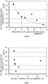
- FIG. 4 A relationship between a proportion of the specific crystal planes of the palladium particles at the interface in each of the catalyst materials of Examples 1 to 7 and the 50% methane purification temperature of the catalyst material is illustrated in FIG. 4 .
- FIG. 5 A relationship between the average particle diameter of the palladium particles and the 50% methane purification temperature of the catalyst material is illustrated in FIG. 5 .
- the 50% methane purification temperature the lower a value of the 50% methane purification temperature is, the lower the temperature at which a high methane purification performance can be achieved is.
- FIG. 4 it was found that, generally, there is a tendency the higher the proportion of the specific crystal planes of palladium at the interface of the catalyst material is, the lower the 50% methane purification temperature is.
- the 50% methane purification temperature was 348.3°C, and is the lowest among those in Examples 1 to 7.
- FIG. 5 it was confirmed that there is no significant relationship between the particle diameter of the palladium particles and the 50% methane purification temperature.
- the catalyst material of Example 1 in which the average particle diameter of the palladium particles was large and exceeded 30 nm presumably, because the average particle diameter of the palladium particles was too coarse, the activity efficiency of the catalyst was reduced and the 50% methane purification temperature was increased.
- the palladium particles are supported such that Pd(100) or PdO(101) equivalent to Pd(100) is a crystal growth plane and these planes are parallel to the surface of the carrier, and thus, a higher methane purification performance can be achieved.
- the higher the proportion of the palladium particles grown in a Pd[100] orientation or a PdO[101] orientation equivalent to the Pd[100] orientation relative to the carrier the higher the methane purification performance is.
- the methane purification performance is higher when the palladium particles are not too coarse (for example, have an average particle diameter of about 30 nm or less, preferably about 20 nm or less).
- the palladium particles preferably have, for example, an average particle diameter of 20 nm or less and the proportion of the specific crystal planes at the interface is about 20 number% or more because the 50% methane purification temperature is below 360°C and the methane purification performance is increased.
- FIG. 6 a relationship between the proportion of the specific crystal planes of the palladium particles at the interface in each of the catalyst materials of Examples 1 to 7 and a proportion of the specific crystal planes of the alumina carrier at the interface of the catalyst material is illustrated in FIG. 6 .
- FIG. 6 it was found that there is a very good correlation between the proportion of the specific crystal planes of the palladium particles at the interface of the catalyst material and the proportion of specific crystal planes of the alumina carrier.
- palladium particles in which an interface that contribute to reduction in the 50% methane purification temperature was a specific crystal plane were present in various proportions ranging from 7 number% (Example 7) to 54 number% (Example 3) of the palladium particles in the catalyst material, and it was found that, as the proportion of the specific crystal planes of alumina serving as the carrier increases, a proportion at which palladium particle growth planes formed thereon are specific crystal planes increases. In other words, it was found that the palladium particles that contribute to reduction in the 50% methane purification temperature are likely to be formed on the specific crystalline planes of the alumina carrier.
- the palladium particles grown on the crystalline alumina carrier exhibit epitaxy, and the more any one of 0(001), 0(111), and ⁇ (104) that are the specific crystal planes is exposed on the surface of the alumina carrier, the more likely it is that the crystal growth planes of palladium crystally grown on the surface can be made Pd(100) or PdO(101) and a growth direction thereof can be coordinated to be a specific direction, that is, Pd[100] or PdO[101] equivalent to the Pd[100], so that a catalyst material having a higher methane purification performance can be realized.
- the proportion of the specific crystal planes at the interface of alumina serving as the carrier is 30 number% or more.
- the average particle diameter of the palladium particles in each of the catalyst materials of Examples 1 to 7 and the proportion of the specific crystal planes at the interface of the alumina carrier are illustrated in FIG. 7 in a relationship with the specific surface area of alumina.
- the average particle diameter of the palladium particles generally exhibits a constant correlation with the specific surface area of alumina. That is, it was found that there is a tendency that the larger the specific surface area of alumina is, the smaller the average particle diameter of the palladium particles formed on the surface thereof is.
- the specific surface area of alumina may be approximately 10 m 2 /g or more in order to cause the average particle diameter of the palladium particles to be smaller than 30 nm, and it is also understood that the specific surface area of alumina may be made approximately 15 m 2 /g or more in order to cause the average particle diameter to be approximately 20 nm or less and may be made approximately 20 m 2 /g or more in order to stably cause the average particle diameter to be 15 nm or less.
- the proportion of specific crystal planes at the interface of the alumina carrier generally exhibits a constant correlation with the specific surface area of alumina. That is, it was found that there is a tendency that the smaller the specific surface area of alumina is, the higher the proportion of a surface on which an alumina specific interface is exposed and palladium particles are oriented and deposited is.
- the proportion of the alumina specific interface in the palladium particle deposited surface increases linearly as the specific surface area reduces in a range in which the specific surface area of alumina is approximately 80 m 2 /g or more and, on the other hand, converges to a certain ratio in a range in which the specific surface area of alumina is approximately 80 m 2 /g or less.
- the specific surface area of alumina may be approximately 90 m 2 /g or less.
- the specific surface area of alumina serving as the carrier is 20 m 2 /g or more and 90 m 2 /g or less because a catalyst material in which the proportion of the palladium particles that contribute to reduction in the 50% methane purification temperature is high can be obtained.
- Example 3 of Test Example 1 In a similar manner to that in Example 3 of Test Example 1 described above, the catalyst material and the catalyst specimen of Example 3 were prepared.
- Example 8 Except that the Pd content of the palladium nitrate aqueous solution and the amount of alumina powder (having a specific surface area of 44 m 2 /g) added in Example 3 of Test Example 1 described above were changed to 1.0 g and 9.0 g, respectively, in a similar manner to that in Example 3, a catalyst material and a catalyst specimen of Example 8 were prepared. A supported ratio of palladium particles (catalyst) in the catalyst material of this Example 8 is 10 mass%.
- Example 9 Except that the Pd content of the palladium nitrate aqueous solution and the amount of alumina powder (having a specific surface area of 44 m 2 /g) added in Example 3 of Test Example 1 described above were changed to 1.5 g and 8.5 g, respectively, in a similar manner to that in Example 3, a catalyst material and a catalyst specimen of Example 9 were prepared. A supported ratio of palladium particles (catalyst) in the catalyst material of this Example 9 is 15 mass%.
- Example 6 of Test Example 1 In a similar manner to that in Example 6 of Test Example 1 described above, the catalyst material and the catalyst specimen of Example 6 were prepared.
- Example 10 Except that the Pd content of the palladium nitrate aqueous solution and the amount of alumina powder (having a specific surface area of 109 m 2 /g) added in Example 6 of Test Example 1 described above were changed to 1.0 g and 9.0 g, respectively, in a similar manner to that in Example 6, a catalyst material and a catalyst specimen of Example 10 were prepared. A supported ratio of palladium particles (catalyst) in the catalyst material of this Example 10 is 10 mass%.
- Example 11 Except that the Pd content of the palladium nitrate aqueous solution and the amount of alumina powder (having a specific surface area of 109 m 2 /g) added in Example 6 of Test Example 1 described above were changed to 1.5 g and 8.5 g, respectively, in a similar manner to that in Example 6, a catalyst material and a catalyst specimen of Example 11 were prepared. A supported ratio of palladium particles (catalyst) in the catalyst material of this Example 11 is 15 mass%.
- Example 3 For the catalyst materials of Examples 3, 6, and 8-11 prepared, the particle diameter of the palladium particles deposited on the surface of the alumina carrier was measured together with the examination of the proportion of the specific crystal planes in a similar manner to that in Example 1. Results of the measurement are illustrated in Table 2 below.
- Example Alumina Palladium Amount (g) Catalyst Body Proportion of Specific Planes (number%) 50% Methane Purification Temperature (°C) Reduction Temperature (°C) Alumina Amount (g) Specific Surface Area (m 2 /g) Pd Particle Diameter (nm) Pd Supported Rate (mass%) Palladium Particles Alumina 3 9.8 44 0.2 7.5 2.0 54 38 348.3 0 8 9.0 44 1.0 13.8 10 37 38 310.5 -37.8 9 8.5 44 1.5 22.1 15 15 25 306.0 -42.3 6 9.8 109 0.2 5.9 2.0 15 25 361.3 13 10 9.0 109 1.0 11.3 10 18 25 315.1 -33.2 11 8.5 109 1.5 18.4 15 14 25 305.0 -43.3
- FIG. 8 A relationship between a palladium supported amount of each of the catalyst materials and the 50% methane purification temperature is illustrated in FIG. 8 . It can be understood that, in each of Examples 3, 8, and 9 using alumina having a relatively small specific surface area as a carrier and Examples 6, 10, and 11 using alumina having a relatively large specific surface area, by increasing a palladium supported ratio of the catalyst material, the 50% methane purification temperature can be lowered and the catalyst material having a high methane purification performance can be obtained. In comparison between Example 9 and Example 11 in which the supported ratio of palladium particles is 15 mass%, as illustrated in FIG. 8 , the 50% methane purification temperature is lower in Example 11 in which the specific surface area of alumina of the carrier is larger.
- Example 3 and Example 8 in which the supported ratio of the palladium particles is even lower, a reverse phenomenon that the 50% methane purification temperature is lower in Example 3 and Example 8 in which the specific surface area of alumina is smaller was observed. Moreover, it was also found that, as the supported ratio of the palladium particles reduces, a difference in the 50% methane purification temperature between the catalyst materials having the same supported ratio of palladium particles increases and, for example, for the catalyst materials of Example 3 and Example 6 in which the supported ratio is 2 mass%, the 50% methane purification temperature is lower by 13 °C in the catalyst material of Example 3 having a specific surface area of 44 m 2 /g than in the catalyst material of Example 6 having a specific surface area of 109 m 2 /g.
- a catalyst material containing only palladium was used as the methane purification catalyst, but there is no particular limitation on an embodiment of the methane purification catalyst.
- a catalyst material containing only palladium a catalyst material containing rhodium, a catalyst material containing platinum, a catalyst material containing rhodium and platinum, or the like may be used.
- a catalyst material containing only palladium and a catalyst material containing some other catalyst than palladium may be used together.
- the internal combustion engine is a CNG engine
- the internal combustion engine provided in combination with a catalyst may be a gasoline engine, a diesel engine, or the like, as long as the engine is used for the purpose of purification of methane.
- these internal combustion engines may be engines mounted on hybrid vehicles which include a vehicle driving power source.
Landscapes
- Chemical & Material Sciences (AREA)
- Engineering & Computer Science (AREA)
- Chemical Kinetics & Catalysis (AREA)
- Materials Engineering (AREA)
- Organic Chemistry (AREA)
- Combustion & Propulsion (AREA)
- Health & Medical Sciences (AREA)
- General Engineering & Computer Science (AREA)
- Mechanical Engineering (AREA)
- Toxicology (AREA)
- Environmental & Geological Engineering (AREA)
- Biomedical Technology (AREA)
- Analytical Chemistry (AREA)
- General Chemical & Material Sciences (AREA)
- Oil, Petroleum & Natural Gas (AREA)
- Ceramic Engineering (AREA)
- Catalysts (AREA)
- Exhaust Gas Treatment By Means Of Catalyst (AREA)
- Exhaust Gas After Treatment (AREA)
Abstract
Description
- The present invention relates to a catalyst material used for purifying exhaust gas containing methane. The present application claims priority from
Japanese Patent Application No. 2019-067927 filed on March 29, 2019 - Exhaust gas emitted from internal combustion engines (engines) of vehicles, such as automobiles or the like, contains harmful gaseous components, such as hydrocarbon (HC), carbon monoxide (CO), nitrogen oxide (NOx), or the like, as well as a particulate matter (PM) which is mainly composed of carbon. Exhaust gas regulations that control emissions of these harmful gases and PM are being tightened every year. Therefore, research is being conducted on internal combustion engines and related technologies to reduce emissions of harmful gases and PM from vehicles or the like.
- Because of their low CO2 emissions per unit distance, vehicles using natural gas internal combustion engines (for example, CNG vehicles) that use natural gas as fuel have attracted attention in recent years. While HC emitted from gasoline internal combustion engines that use gasoline as fuel are aromatics, olefins, paraffins, or the like that are components easily burned at relatively low temperature, HC emitted from natural gas internal combustion engines are mostly methane (CH4) that is chemically stable and difficult to decompose at low temperature. Known technologies for catalysts used for purifying methane contained in exhaust gas of such natural gas internal combustion engines include, for example,
Patent Documents 1 to 5. -
- PATENT DOCUMENT 1:
Japanese Laid-open Patent Publication No. 2002-336655 - PATENT DOCUMENT 2:
Japanese Laid-open Patent Publication No. 2002-263491 - PATENT DOCUMENT 3:
Japanese Laid-open Patent Publication No. 2001-190931 - PATENT DOCUMENT 4:
Japanese Laid-open Patent Publication No. 2008-246473 - PATENT DOCUMENT 5:
Japanese Laid-open Patent Publication No. 2014-091119 - Incidentally, it is when an exhaust gas purification catalyst has been warmed up to temperature at which the catalyst is activated by exhaust gas that the exhaust gas purification catalyst functions. Therefore, it is difficult to purify methane in the exhaust gas during cold start-up of an internal combustion engine, and there is a risk that unpurified methane is released into the atmosphere. Although natural gas internal combustion engines that use natural gas as fuel emit a low amount of CO2 per unit distance, 80 mass% or more of HC in the exhaust gas is methane, and this can be a significant problem in a point that methane has a high global warming potential, that is, a
global warming potential 25 times higher than that of CO2. - In view of the foregoing, the present invention has been devised and it is therefore an object of the present invention to provide an exhaust gas purification catalyst having an excellent purification performance for purifying chemically stable methane.
- The present invention provides a catalyst material used for purifying methane. The catalyst material includes a carrier formed of alumina and a catalyst formed of at least one of palladium and a palladium oxide directly supported by the carrier. A specific surface area of the carrier is 20 m2/g or more and 90 m2/g or less.
- According to the above-described structure, the specific surface area of alumina that is the catalyst carrier is limited to a specific range. For alumina having the above-described specific surface area, each of crystal structures of palladium and a palladium oxide that are crystally grown and supported directly on a surface thereof can be made into a crystal structure in which a specific crystal orientation is high. As a result, for example, 50% methane purification temperature of palladium and the palladium oxide that are catalysts can be lowered and a methane purification performance of the catalyst material can be increased.
- In one preferred aspect of the catalyst material provided by the technology disclosed herein, a proportion of Pd(100) and PdO(101) in crystal planes of the catalyst at a joint surface between the catalyst and the carrier is 20 number% or more. According to the above-described structure, the methane purification performance can be preferably increased more reliably.
- In one preferred aspect of the catalyst material provided by the technology disclosed herein, a proportion of 0(001), 0(111), and α(104) in crystal planes of the carrier at a joint surface between the catalyst and the carrier is 30 number% or more. According to the above-described structure, the proportion of Pd(100) and PdO(101) of the catalyst at the joint surface can be increased, and consequently, a catalyst material having an excellent methane purification performance can be preferably obtained.
- In one preferred aspect of the catalyst material provided by the technology disclosed herein, an average particle diameter of the catalyst is 20 nm or less. According to the above-described structure, a contact efficiency of the catalyst with methane gas per unit mass can be preferably increased. Furthermore, it is preferable that the average particle diameter of the catalyst is 10 nm or less because a catalyst activity is further increased due to a sizing effect.
- In one preferred aspect of the catalyst material provided by the technology disclosed herein, a supported ratio of the catalyst to a total amount of the carrier and the catalyst is 10 mass% or less. The catalyst material disclosed herein can exhibit a high methane purification performance with a smaller catalyst amount. Therefore, in a case where the supported ratio of the catalyst is made 10 mass% or less, particularly, the above-described effects can be preferably exhibited in a clear manner.
- In one preferred aspect of the catalyst material provided by the technology disclosed herein, the catalyst material is used for purifying exhaust gas emitted from an internal combustion engine using natural gas as fuel. In a case where the internal combustion engine uses natural gas as fuel, 80 mass% or more of HC contained in the exhaust gas can be methane. The exhaust gas purification catalyst of the technology disclosed herein preferably exhibits the above-described effects in a case where the exhaust gas purification catalyst is used for purifying the exhaust gas having a high content of methane.
- As has been described above, the catalyst material disclosed herein has an excellent methane purification performance, and for example, the purification rate for methane in gas can be made 50% or more in a lower temperature range. This feature is preferable because, when the catalyst material is preferably used for purifying methane contained in exhaust gas at relatively low temperature, for example, during cold start-up of the internal combustion engine, during idling stop control, or the like, advantages thereof can be fully exhibited. Therefore, the catalyst material can be preferably used as a catalyst material in an exhaust gas purification catalyst body for, for example, a natural gas (CNG) engine, a gasoline engine, a diesel engine, or the like. The catalyst material can be preferably used in a case where the internal combustion engine is an internal combustion engine of a vehicle (including a hybrid vehicle, a plug-in hybrid vehicle, or the like including a driving power source, in addition to an engine vehicle) with relatively large fluctuations in rotation speed. It is particularly preferable to use the catalyst material as a catalyst material of an exhaust gas purification catalyst body of a CNG engine in which a proportion of methane in HC contained in exhaust gas is high.
-
- [
FIG. 1] FIG. 1 is a partial cross-sectional view schematically illustrating a structure of a catalyst body according to one embodiment. - [
FIG. 2] FIG. 2 is a schematic view illustrating a configuration of an exhaust gas purification system according to one embodiment. - [
FIG. 3A] FIG. 3A is a perspective view schematically illustrating an exhaust gas purification catalyst according to one embodiment. - [
FIG. 3B] FIG. 3B is a partial cross-sectional view schematically illustrating a structure of a catalyst layer in the exhaust gas purification catalyst according to one embodiment. - [
FIG. 4] FIG. 4 is a graph illustrating a relationship between a proportion of specific crystal planes of palladium at a catalyst-carrier interface and 50% methane purification temperature for catalyst bodies of examples. - [
FIG. 5] FIG. 5 is a graph illustrating a relationship between an average particle diameter of palladium and 50% methane purification temperature for catalyst bodies of examples. - [
FIG. 6] FIG. 6 is a graph illustrating a relationship between a proportion of specific crystal planes of palladium and a proportion of specific crystal planes of alumina at a catalyst-carrier interface for catalyst bodies of examples. - [
FIG. 7] FIG. 7 is a graph illustrating a relationship between an average particle diameter of palladium, a proportion of specific crystal planes of alumina, and a specific surface area of alumina for catalyst bodies of examples. - [
FIG. 8] FIG. 8 is a graph illustrating a relationship between a palladium supported ratio and 50% methane purification temperature for catalyst bodies of examples. - Preferred embodiments of the present invention will be described below with reference to the accompanying drawings. Note that matters other than matters specifically mentioned in this specification and necessary for the implementation of the present invention can be understood as design matters carried out by those skilled in the art, based on the conventional art in the field. The present invention can be implemented based on the contents disclosed in this specification and the common general technical knowledge in the field. Moreover, in the following drawings, members/parts that have the same effect may be denoted by the same sign and the overlapping description may be omitted or simplified. Dimensional relations (length, width, thickness, or the like) in the drawings do not necessarily reflect actual dimensional relations. Note that, in this specification, the notation "A to B" indicating a numerical range means "A or more and B or less."
-
FIG. 1 is a cross-sectional view illustrating a structure of acatalyst material 30 according to one embodiment. Thecatalyst material 30 disclosed herein is a catalyst material used for purifying methane. Thecatalyst material 30 includes acarrier 32 and acatalyst 34 directly supported by thecarrier 32. Constituent components of thecatalyst material 30 will be described below. - In the
catalyst material 30 disclosed herein, thecarrier 32 that supports thecatalyst 34 is formed of alumina. There is no particular limitation on a crystal structure of alumina. Various polymorphic forms of alumina, such as γ-alumina, δ-alumina, θ-alumina, α-alumina, or the like, are known, and the crystal structure of alumina as thecarrier 32 may include one or two or more of the above-described polymorphic forms. Alumina other than α-alumina of a high temperature stable phase is referred to as transition alumina (also referred to as intermediate alumina), generally has ultra-fine primary particles, and has a large specific surface area. As an alumina carrier of a known catalyst for automobiles, in general, an intermediate alumina, that is, a γ-alumina having a particularly high specific surface area has been widely used. On the other hand, according to a study conducted by the present inventors, alumina as thecarrier 32 preferably has a relatively small specific surface area, that is, a specific surface area of 90 m2/g or less (for example, 20 m2/g or more and 90 m2/g or less). - Although there is no unambiguous relationship between a specific surface area of a crystal and a crystal plane appearing on a surface of the crystal, according to the study of the inventors, it was found that there is a certain degree of correlation between the specific surface area of alumina and the crystal plane appearing on the surface thereof. The inventors found that, in alumina having such a specific surface area, a special crystal plane on which the
catalyst 34 can be easily grown in a preferable external form is exposed on the surface thereof at a high proportion. Such special crystal planes of alumina (which will be occasionally hereinafter referred to simply as "the specific planes of alumina" or the like) are θ(001), θ(111), and α(104) of alumina. By using such alumina as a carrier, generation of thecatalyst 34 having a specific crystal orientation on a surface thereof can be promoted, for example, in a method for manufacturing thecatalyst material 30 described later, and therefore, use of such alumina as a carrier is preferable. - The specific surface area of alumina serving as the
carrier 32 is appropriately 90 m2 or less, preferably 85 m2/g or less, and may be 80 m2/g or less or 75 m2/g or less, that is, for example, 60 m2/g or less in view of increasing a proportion at which the crystal plane on which thecatalyst 34 in a preferable external form can be easily grown is exposed on the surface thereof. However, it is not preferable that the specific surface area of alumina serving as thecarrier 32 is too small because a proportion of flat surfaces, that is, in other words, the specific crystal planes, in the external form of alumina becomes excessively high and the carriedcatalyst 34 tends to grow coarsely when the carriedcatalyst 34 is generated or when the catalyst material is used. In view of the foregoing, the specific surface area is, for example, appropriately 15 m2/g or more, preferably 20 m2/g or more, and may be 25 m2/g or more, 30 m2/g or more (for example, more than 30 m2/g), or 35 m2/g or more, that is, for example, 40 m2/g or more. - If the
carrier 32 has the above-described specific surface area, there is no particular limitation on a shape of thecarrier 32. As one preferable example, thecarrier 32 may be formed of powdered alumina and/or porous alumina. In a case where thecarrier 32 is powdered alumina, an average particle diameter of thecarrier 32 is, for example, preferably 20 µm or less, typically 10 µm or less, or 7 µm or less, that is, for example, 5 µm or less. Moreover, the average particle diameter of thecarrier 32 may be typically 0.1 µm or more, that is, for example, 0.5 µm or more, 1 µm or more, or 3 µm or more in view of increasing a heat resistance of thecatalyst material 30. - Note that, in this specification, the average particle diameter of a material that is the
catalyst material 30, thecarrier 32, or the like and is in a form of powder is cumulative 50% particle diameter (Dso) in a volume-based particle diameter distribution measured by a laser diffraction scattering method. - Moreover, the specific surface area of the
carrier 32 is a value calculated by a BET method (for example, a BET one-point method), based on an amount of gas absorbed measured by a gas absorption method (a constant capacity adsorption method). There is no particular limitation on an adsorbate in the gas absorption method and, for example, nitrogen (N2) gas can be preferably used. - In the
catalyst material 30 disclosed herein, thecatalyst 34 is formed of at least one of palladium and a palladium oxide. Thecatalyst 34 is supported directly and integrally on a surface of alumina serving as thecarrier 32. In other words, thecatalyst 34 is bonded to the surface of thecarrier 32 without a binding agent, such as a binder or the like. For example, specifically, thecatalyst 34 is supported on the surface of alumina serving as the carrier through crystal growth directly thereon. At this time, thecatalyst 34 crystally grows on the surface of alumina and, when the crystal plane of alumna serving as thecarrier 32 is the above-described specific plane, crystal growth of thecatalyst 34 with a certain crystal orientation relationship with the specific plane of alumina tends to be induced. Crystal planes of palladium (Pd) and a palladium oxide (PdO) whose growth tends to be induced on the specific plane of alumina are Pd(100) and PdO(101) (which will be hereinafter occasionally referred to as simply "the palladium specific planes"). In other words, Pd tends to grow in a (100) plane orientation on the specific plane of alumina serving as thecarrier 32. Alternatively, PdO tends to grow in a (101) plane orientation. As for Pd and PdO, for example, Pd is easily oxidized into PdO and PdO is easily reduced to Pd by reversible change of an electronic state of Pd due to fluctuations of an atmosphere of exhaust gas. In this oxidation-reduction reaction of Pd and PdO, Pd(100) and PdO(101) are equivalent planes and Pd and PdO can be equally treated in thecatalyst 34 disclosed herein. In thecatalyst 34 disclosed herein, a valence number of Pd in a palladium oxide may be a value larger than +2 (for example, a value of about +2 to +3). - As described above, palladium (Pd) and a palladium oxide (PdO) as the
catalyst 34 tend to epitaxially grow on the above-described specific plane of alumina serving as thecarrier 32. Based on this, the catalyst material disclosed herein has a structure in which thecarrier 32 and thecatalyst 34 are plane-oriented at a high proportion, as illustrated inFIG. 1 . For example, a proportion of the specific planes of palladium in the crystal planes of thecatalyst 34 at a joint surface of thecatalyst 34 with thecarrier 32 can be 20 number% or more. Based on the study of the present inventors, it was confirmed that, as the proportion of the specific planes of palladium is increased as described above, a methane purification performance of thecatalyst material 30 is increased. Although details are not clear, it can be considered that, due to oriented growth of Pd and PdO serving as thecatalyst 34, a specific crystal plane, a growth step, or the like is formed in a crystal external form of thecatalyst 34 and this provides an active point in a methane purification reaction. - As for the proportion of the specific planes of palladium at a catalyst-carrier interface of the
catalyst material 30, as the proportion increases, for example, 50% methane purification temperature reduces or the like, so that the methane purification performance is increased. The proportion of the specific planes of palladium is preferably 20 number% or more, more preferably 25 number% or more, and may be, for example, 30 number% or more, 35 number% or more, 40 number% or more, or the like. There is no particular limitation on an upper limit of the proportion of the specific planes of palladium at the catalyst-carrier interface, and the upper limit may be substantially 100 number% or less (for example, 100 number%) and may be, for example, 95 number% or less, 90 number% or less, 85 number% or less, 80 number% or less, 70 number% or less, or the like. - Note that, herein, as described above, growth of the specific planes of palladium at the catalyst-carrier interface can be induced by the specific planes of alumina. In view of this, in the crystal planes of alumina forming the catalyst-carrier interface, a proportion of the specific planes of alumina is preferably large. Accordingly, the proportion of the specific planes of alumina at the interface is preferably 30 number% or more, more preferably 32 number% or more, and may be, for example, 35 number% or more. There is no particular limitation on an upper limit of the proportion of the specific planes of palladium at the catalyst-carrier interface, and the upper limit may be 100 number% or less (for example, 100 number%) and may be substantially 50 number% or less and 45 number% or less, that is, for example, about 40 number% or less or the like.
- Note that, in the technology disclosed herein, the crystal planes forming the interface between the
catalyst 34 and thecarrier 32 can be specified by a known method by observation using a transmission electro microscope (TEM). In one example, a crystal structure image or a crystal photon image at the interface between thecatalyst 34 and thecarrier 32 may be obtained and the crystal planes forming the interface may be identified for each of thecatalyst 34 and thecarrier 32. Identification of the crystal planes may be performed based on a known crystal plane spacing (lattice spacing), the crystal planes may be identified using an electron diffraction observation mode of TEM. In this specification, as described in examples below, the crystal planes are identified based on the crystal plane spacing. - Note that sizes of palladium (Pd) and a palladium oxide (PdO) serving as the
catalyst 34 are not strictly limited. In view of cost cut or the like, thecatalyst 34 may be a particulate catalyst (which will be hereinafter referred to as catalyst particles or the like) having a large specific surface area and, for example, 90 number% or more of the catalyst particles preferably have a particle diameter of about 20 nm or less that exhibits a sizing effect. An average particle diameter of the catalyst particles may be, for example, 15 nm or less, more preferably 10 nm or less, and typically 8 nm or less or 7 nm or more. There is no particular limitation on a lower limit on the average particle diameter of the catalyst particles, and the lower limit is typically approximately 0.1 nm or more and may be, for example, 1 nm or more. - Note that the average particle diameter of the catalyst particles is a value (volume sphere equivalent diameter) calculated by a pulse absorption method using carbon monoxide (CO) as an absorption gas. The pulse absorption method was performed in accordance with "a metal surface area measuring method using a CO pulse method" by the Reference Catalyst Division, of the Catalysis Society of Japan.
- In the
catalyst material 30 disclosed herein, there is no particular limitation on a supported amount of thecatalyst 34 supported, but when the supported amount of thecatalyst 34 supported is too small, a catalyst activity achieved by thecatalyst 34 is insufficient, and therefore, it is not preferable that the supported amount of thecatalyst 34 is too small. As one example, as the supported amount of thecatalyst 34 that is preferable as an exhaust gas purification catalyst, for example, a proportion (supported amount) of thecatalyst 34 to a total mass of thecatalyst material 30 is appropriately 0.001 mass% or more, preferably 0.01 mass% or more, and may be, for example, 0.1 mass% or more. On the other hand, when the supported amount of thecatalyst 34 is too large, particle growth of thecatalyst 34 tends to be induced and the too large supported amount of thecatalyst 34 is disadvantageous in terms of cost. Therefore, the proportion of thecatalyst 34 to the total mass of thecatalyst material 30 may be, for example, 10 mass% of less, is preferably 8 mass% or less, and typically may be 5 mass% or less. - The above-described catalyst material 30 can be obtained by integrally forming and supporting palladium or a palladium oxide on a surface of alumina serving as the
carrier 32 such that a proportion of Pd(100) or PdO(101) at a joint surface (crystal interface) is large. As a method for manufacturing thecatalyst material 30, as one preferred example, for example, thecatalyst material 30 can be prepared by, after immersing thecarrier 32 in an aqueous solution containing a salt (for example, nitrate) or a complex (for example, tetraammine complex) containing a palladium component that is thecatalyst 34, drying and baking thecarrier 32, although the method is not limited thereto. At this time, by using alumina having the above-described specific surface area as thecarrier 32, thecatalyst material 30 in which the proportion of the specific planes of palladium at the interface is large can be obtained. - The above-described
catalyst material 30 is provided as a catalyst material having an excellent methane purification performance. Accordingly, thecatalyst material 30 can be preferably used, for example, as a purification catalyst or the like used for purifying exhaust gas of internal combustion engines using natural gas as fuel. An exhaust gas purification system using thecatalyst material 30 will be briefly described below. -
FIG. 2 is a schematic view illustrating an exhaustgas purification system 1 according to one embodiment. The exhaustgas purification system 1 purifies harmful components, that is, for example, HC, CO, and NOx, contained in exhaust gas emitted from aninternal combustion engine 2 and collects PM contained in the exhaust gas. The exhaustgas purification system 1 includes theinternal combustion engine 2 and an exhaust passage. The exhaustgas purification system 1 of this embodiment includes theinternal combustion engine 2, the exhaust passage, an engine control unit (ECU) 7, and asensor 8. The exhaust gas purification catalyst in this technology is provided in the exhaust passage of theinternal combustion engine 2 as one constituent component of the exhaustgas purification system 1. The exhaust gas circulates in the exhaust passage. Arrows inFIG. 2 indicate an exhaust gas flow direction. Note that, in this specification, along a flow of the exhaust gas, a side closer to theinternal combustion engine 2 is an upstream side and a side farther from theinternal combustion engine 2 is a downstream side. - An air-fuel mixture containing oxygen and fuel gas is supplied to the
internal combustion engine 2. Theinternal combustion engine 2 converts thermal energy generated by burning the air-fuel mixture to kinetic energy. A ratio between oxygen and the fuel gas supplied to theinternal combustion engine 2 is controlled byECU 7. The burned air-fuel mixture becomes exhaust gas and thus is discharged to the exhaust passage. Theinternal combustion engine 2 having the structure ofFIG. 1 is mainly constituted by an internal combustion engine using natural gas as fuel. - The
internal combustion engine 2 is coupled to the exhaust passage at an unillustrated exhaust port. The exhaust passage of this embodiment is constituted by anexhaust manifold 3 and anexhaust pipe 4. Theinternal combustion engine 2 is coupled to theexhaust pipe 4 via theexhaust manifold 3. Typically, the exhaust passage includes acatalyst body 5 and afilter body 6. For example, thecatalyst body 5 includes a catalyst body according to the technology disclosed herein. For example, thecatalyst body 5 may include some other catalyst, such as a binary catalyst, an HC selective reduction type NOx catalyst, a NOx storage reduction catalyst, a urea selective reduction type NOx catalyst, or the like. Thefilter body 6 is not an essential component and the exhaust passage may include thefilter body 6 as necessary. In a case where the exhaust passage incudes thefilter body 6, a structure thereof may be similar to a known structure and there is no particular limitation thereon. Thefilter body 6 may be, for example, a particulate filter (PF) that supplements fine PMs to reduce the number of the fine PMs discharged, a catalyst particulate filter or the like configured to have a catalyst purification function by causing the particulate filter to support a binary or ternary catalyst or the like, or the like. Note that thecatalyst material 30 disclosed herein can be used as the catalyst in the catalyst particulate filter. An arrangement of thecatalyst body 5 and thefilter body 6 is arbitrarily variable, and one or more of each of thecatalyst body 5 and thefilter body 6 may be independently provided. - The
ECU 7 is electrically coupled to theinternal combustion engine 2 and thesensor 8. TheECU 7 receives signals from various sensors (for example, an oxygen sensor, a temperature sensor, a pressure sensor) 8 that detect an operation state of theinternal combustion engine 2 and controls driving of theinternal combustion engine 2. A configuration of theECU 7 may be similar to a known configuration, and there is no particular limitation thereon. TheECU 7 is, for example, a processor or an integrated circuit. The ECU 26 receives, for example, information of an operation state of a vehicle or the like, an amount, temperature, and a pressure of exhaust gas emitted from theinternal combustion engine 2, or the like. Moreover, theECU 7 performs operation control, such as fuel injection control, ignition control, intake air amount adjustment control, or the like, for theinternal combustion engine 2, for example, in accordance with the received information. -
FIG. 3A is a perspective view of acatalyst body 5 according to one embodiment. The reference character X inFIG. 2 indicates a first direction of thecatalyst body 5. Thecatalyst body 5 is installed in theexhaust pipe 4 such that the first direction matches the exhaust gas flow direction. For convenience, when a focus is put on a flow of the exhaust gas, one direction X1 of the first direction X is referred to as an exhaust gas inflow side (upstream side) and the other direction X2 thereof is referred to as an exhaust gas outflow side (downstream side). For thecatalyst body 5, occasionally, the one direction X1 is referred to as a front side and the other direction X2 is referred to as a rear side.FIG. 3B is a schematic view illustrating an enlarged portion of a cross section of thecatalyst body 5 according to one embodiment taken along the first direction X. Thecatalyst body 5 disclosed herein includes, for example, abase material 10 having a straight flow structure and acatalyst layer 20. Thebase material 10 and thecatalyst layer 20 will be described below in this order. - For the
base material 10, known base materials made of various raw materials in various forms used for this kind of application can be used. Thebase material 10 typically has a so-called honeycomb structure. For thebase material 10, for example, a base material formed of a material represented by ceramics, such as cordierite, aluminum titanate, silicon carbide (SiC), or the like, an alloy, such as stainless steel, or the like, having a high heat resistance and a high resistance to abrupt temperature change can be preferably employed. There is no particular limitation on an external form of thebase material 10 and examples of thebase material 10 include a base material having a columnar shape (this embodiment). However, as for an external form of an entire base material, in addition to a columnar shape, an elliptical columnar shape, a polygonal pillar shape, an amorphous shape, a pellet shape, or the like may be employed. In this embodiment, a column axis direction of thebase material 10 having a columnar shape matches the first direction X. An end portion in the one direction X1 of thebase material 10 is afirst end portion 10a and an end portion in the other direction X2 is asecond end portion 10b. In this embodiment, a dimension of a constituent component, such as thebase material 10 or the like, along the first direction X is referred to as a length. - In the
base material 10, cells (cavities) 12 in the honeycomb structure extend in the first direction X. Thecells 12 are through holes that pass through thebase material 10 in the first direction X and serve as a passage of exhaust gas. Thebase material 10 includespartition walls 14 that define thecells 12. There is no particular limitation on a shape of a cross section of thecell 12 orthogonal to the first direction X (which will be hereinafter referred as simply to a "cross section"), in other words, a structure of thepartition wall 14 that defines the cell. Thecell 12 may have various geometrical shapes, such as, for example a rectangular shape, such as a square, a parallelogram, a rectangle, a trapezoid, or the like, a triangular shape, other polygonal shapes (for example, a hexagon, an octagon), a circle, or the like. The shape, the size, the number, or the like of thecells 12 can be appropriately designed in consideration of a flow rate or components of exhaust gas supplied to thecatalyst body 5. - The
partition walls 14 face thecells 12 and each of thepartition walls 14 partitions corresponding adjacent ones of thecells 12. A thickness (dimension in a direction orthogonal to a surface. The same applies below) Tw of thepartition wall 14 is preferably small because, when the thickness Tw is small, a specific surface area of thebase material 10 can be increased and reduction in weight and thermal capacity can be achieved. The thickness Tw of thepartition wall 14 can be, for example, 1 mm or less, 0.75 mm or less, 0.5 mm or less, 0.1 mm or less, or the like. On the other hand, with thepartition wall 14 having an appropriate thickness, strength and durability of thecatalyst body 5 are increased. In view of the foregoing, the thickness Tw of thepartition wall 14 may be, for example, 0.01 mm or more and 0.025 mm or more. There is no particular limitation on a length (entire length) Lw of thepartition wall 14 in the X direction and the length may be generally 50 to 500 mm, that is, for example, about 100 to 200 mm. Note that, in this specification, a volume of thebase material 10 is an apparent volume of the base material. Therefore, the volume of thebase material 10 includes, in addition to a substantial volume of the honeycomb structure (including the partition walls 14) that is a framework, a cubic content of thecells 12. - As illustrated in
FIG. 3B , thecatalyst layer 20 is disposed on a surface of thepartition wall 14. Thecatalyst layer 20 contains, as a palladium catalyst that is a noble metal catalyst, thecatalyst material 30 disclosed herein. By forming a Pd layer of thecatalyst body 5 using thecatalyst material 30 provided by this technology, methane can be purified at temperature ranging from lower temperature, and thus, an amount of methane emission can be reduced. In other words, thecatalyst body 5 having an excellent methane purification performance can be provided. - Note that the
catalyst layer 20 may include some other noble metal catalyst with the palladium catalyst. Alternatively, thecatalyst body 5 may include a catalyst layer containing unillustrated some other noble catalyst separately from the catalyst layer 20 (which will be hereinafter referred to as "the palladium (Pd) layer") containing the palladium catalyst. As the some other catalyst layer, a platinum (Pt) layer and a rhodium (Rh) layer can be considered. The Pt layer contains platinum (Pt) and an alloy mainly containing Pt as a noble metal catalyst. The Rh layer contains rhodium (Rh) and an alloy mainly containing Rh as a noble metal catalyst. Each of thecatalyst layer 20 and the other catalyst layers may contain some other metal catalyst, in addition to the above-described noble metal catalysts. Examples of the metal catalyst include Rh, Pd, Pt, ruthenium (Ru), osmium (Os), iridium (Ir), platinum group catalysts that are alloys of the above-described metals, and, in addition to these platinum group elements or instead of the above-described platinum groups, metals including a metal element, such as, for example, iron (Fe), cobalt (Co), nickel (Ni), copper (Cu), silver (Ag), gold (Au), or the like or alloys thereof, or the like. However, each of the metal catalysts contained in the Pd layer, the Pt layer, and the Rh layer may be a corresponding one of Pd, Pt, and Rh in an amount of 80 mass% or more, preferably in an amount of 90 mass% or more, more preferably in an amount of 95 mass% or more, and particularly preferably in an amount of substantially 100 mass%. As a matter of course, it is allowed that some other metal catalyst inevitably mixed therein is contained therein. - Among the Pd layer, the Pt layer, and the Rh layer, the Pd layer and the Pt layer are highly active particularly as oxidation catalysts and exhibits, in the
catalyst body 5, a high oxidation activity for CO and HC, in particular, among harmful components in the exhaust gas. The Rh layer is highly active particularly as a reduction catalyst and exhibits, in thecatalyst body 5, a high reduction activity for NOx, in particular, among the harmful components in the exhaust gas. Thecatalyst body 5 includes the Pd layer, the Pt layer, and the Rh layer, and thus, has a function as a ternary catalyst. There is no particular limitation on an arrangement of the Pd layer, the Pt layer, and the Rh layer, but the Pd layer is more preferably arranged in a relatively front side (for example, an area extending from thefirst end portion 10a of the upstream side toward the downstream side) because, for example, the 50% methane purification temperature can be further reduced. The Pt layer is more preferably arranged in a relatively rear side (for example, an area extending from thesecond end portion 10b of the downstream side toward the upstream side). The Rh layer is more preferably arranged in a longer area along the first direction (for example, arranged so as to be stacked with the Pd layer and the Pt layer) in view of enhancing NOx purification performance. - Each of the Pt layer and the Rh layer can contain, in addition to a noble metal catalyst contained in each of the layers, a carrier that supports the catalysts. As the carrier, any carrier (typically powder) that has been known to be usable for this type of application conventionally can be appropriately employed. For example, preferable examples of the carrier include a metal oxide, such as alumina (Al2O3), a rare earth metal oxide, an alkali metal oxide, an alkaline earth metal oxide, ceria (CeO2), zirconia (ZrO2), silica (SiO2), magnesia (MgO), titania (TiO2), or the like, or a solid solution of each of these metal oxides, such as, for example, a ceria-zirconia composite oxide (CZ composite oxide: CeO2-ZrO2). One of the above-described metal oxides and the solid solutions may be used alone, and two or more of them may be used in combination. Among them, it is preferable to use at least one of alumina and a CZ composite oxide. The carrier may be a polycrystalline material or a monocrystalline material.
- Each of the Pd layer, the Pt layer, and the Rh layer may appropriately contain an arbitrary component, in addition to the noble metal catalyst and the carrier of the noble metal catalyst. Examples of the arbitrary component include, for example, a promotor that does not support a metal catalyst, an oxygen storage material (OSC material: oxygen storage capacity) having an oxygen storage capacity, a NOx adsorbent having a NOx storage capacity, a stabilizer, or the like. Examples of the promotor include, for example, alumina or silica. Examples of the OSC material include, for example, ceria, or a ceria-containing composite oxide, that is, for example, a CZ composite oxide.
- Examples of the stabilizer include, for example, a rare earth element, such as lanthanum (La), yttrium (Y), or the like, an alkaline earth element, such as calcium (Ca), barium (Ba), or the like, other transition metal elements, or the like. The above-described elements are typically present in the catalyst layer in a form of an oxide. Among them, a rare earth element, such as lanthanum, yttrium, or the like, is preferably used as the stabilizer because the rare earth element can increase a specific surface area at high temperature without interfering with a catalyst function. The carrier can be a polycrystalline material or a monocrystalline material. In the
catalyst layer 20, the Pd layer containing an oxidation catalyst preferably contains the stabilizer, such as, for example, a barium element. Thus, poisoning of the oxidation catalyst is preferably suppressed and a catalyst activity can be improved. In addition, dispersibility of the oxidation catalyst is enhanced, and particle growth of the oxidation catalyst can be suppressed at a higher level. - There is no particular limitation on an amount of coating of each of the Pd layer, the Pt layer, and the Rh layer. In view of increasing circulation of the exhaust gas at the
partition walls 14 to reduce pressure loss, the amount of coating may be generally 120 g/L or less, 100 g/L or less, and preferably 80 g/L or less, that is, for example, 70 g/L or less, for 1 L of the base material in terms of volume. In some aspects, the amount of coating may be, for example, 50 g/L or less, and typically 30 g/L or less. On the other hand, in view of further increasing an exhaust gas purification performance for methane and other exhaust gases, the amount of coating may be generally 5 g/L or more, preferably 10 g/L or more, that is, for example, 20 g/L or more, for 1 L of the base material in terms of volume. By satisfying the above range, both reduction in pressure loss and increase in exhaust gas purification performance can be achieved at a higher level. Note that the amount of coating for thecatalyst layer 20 refers to a mass of thecatalyst layer 20 contained in the base material per unit volume. However, the volume of the base material is considered only for a portion of the base material where therelevant catalyst layer 20 is formed along the first direction X, and not for the other portion of the base material where therelevant catalyst layer 20 is not formed. - There is no particular limitation on a thickness of each of the Pd layer, the Pt layer, and the Rh layer, and the thickness thereof can be appropriately designed in accordance with the size or the like of the
cells 12 of thebase material 10. As one example, the thickness of each of the Pd layer, Pt layer, and Rh layer is appropriately about 20 µm to 500 µm, independently, and is preferably, for example, about 50 µm to 200 µm. - Note that the
catalyst body 5 having the above-described structure can be manufactured, for example, by the following method. First, thebase material 10 and slurries used for forming thecatalyst layer 20 are prepared. As the slurries, a slurry for forming a Pd layer, a slurry for forming a Pt layer, and a slurry for forming a Rh layer may be prepared. The slurries for forming the catalyst layers contain different metal catalyst components (typically a solution containing metal catalysts as ions) as essential components, and each of the slurries can contain other arbitrary components, such as, for example, a carrier, a promotor, an OSC material, a binder, various additives, or the like. Note that, as the binder, an alumina sol, a silica sol, or the like can be employed. Note that properties (viscosity, solid fraction, or the like) of each of the slurries may be appropriately adjusted depending on the size of thebase material 10 to be used, the form of the cells 12 (partition walls 14), desired properties of thecatalyst layer 20, or the like. - For example, an average particle diameter of particles in the slurries can be approximately 0.3 µm or more, preferably 0.4 µm or more, more preferably 0.5 µm or more, and can be approximately 3 µm or less, preferably 1 µm or less, and more preferably 0.7 µm or less. Moreover, generally, for example, the slurries for forming the catalyst layers may be prepared such that a viscosity η400 at temperature of 25 °C and a shear rate of 400 s-1 is 50 mPa·s or more and 150 mPa·s or less and preferably about 60 mPa·s or more and 110 mPa·s or less. Note that the above-described slurry viscosity is a viscosity measured under a temperature environment of 25 °C using a commercially available shear viscometer.
- Next, the prepared slurries for forming the catalyst layers are fed into the
cells 12 from an end portion of thebase material 10 to flow in up to a predetermined length along the X direction. In a case of forming the Pd layer, the slurry may be fed from thefirst end portion 10a to flow in up to the length L1 in the X2 direction. In a case of forming the Pt layer, the slurry is fed from thesecond end portion 10b to flow in up to a predetermined length in the X1 direction. In a case of forming the Rh layer, the slurry may be fed from either thefirst end portion 10a or thesecond end portion 10b, and may be fed to flow up to a desired length. At this point, the slurry may be sucked from an end portion at an opposite end. The excessive slurry may also be discharged by blowing air from the end portion at the opposite side. At this time, suction speed and/or blowing speed depends on the viscosity of the slurry, but is generally 10 to 100 m/s, preferably 10 to 80 m/s, and may be, for example, 50 m/s or less. Thereafter, each time one slurry is supplied, thebase material 10 supplied with the slurry is dried and baked at predetermined temperature for a predetermined time. Thus, particulate raw materials are sintered, thereby forming aporous catalyst layer 20. A similar method for drying and baking to those used for forming a known catalyst layer may be used. Thus, thecatalyst layer 20 can be formed on a surface of thepartition wall 14 of thebase material 10. - According to the
catalyst body 5 having the above-described structure, the exhaust gas emitted from theinternal combustion engine 2 flows in thecells 12 from thefirst end portion 10a of thebase material 10. The exhaust gas that has flowed in thecells 12 passes through thecatalyst layer 20 formed on the surface of thepartition wall 14 and is discharged from thesecond end portion 10b. Herein, for example, the Pd layer is disposed in the upstream side of thecatalyst layer 20. The Pd layer contains thecatalyst material 30 disclosed herein. For example, thecatalyst material 30 can cause the 50% methane purification temperature to be lower than 360°C and has an excellent low temperature purification performance. Therefore, even in a case where the exhaust gas contains methane as HC and the temperature of the exhaust gas tends to be lowered by, for example, F/C control, or the like, thecatalyst body 5 can purify a larger amount of methane at lower temperature than that in a known technology. The exhaust gas is also warmed up to higher temperature by a catalytic reaction at the upstream side. The exhaust gas that has passed through the Pd layer with the Rh layer stacked thereon passes through the Pt layer with the Rh layer stacked thereon. Since the exhaust gas that has reached the Pt layer and the Rh layer is warmed up to even higher temperature, the harmful components including methane are purified from the exhaust gas at a high purification rate while passing through the Pt layer with Rh layer stacked thereon. With the Rh layer provided, NOx components in the exhaust gas are also purified. Thus, the exhaust gas is discharged from theend portion 10b on an exhaust gas outflow side to outside of thecatalyst body 5 with the harmful components removed. - Test examples related to the present invention will be described below, but it is not intended to limit the present invention to the test examples below.
- As a carrier, 9.8 g of alumina powder having a specific surface area of 6 m2/g was prepared, was dispersed in a palladium nitrate aqueous solution adjusted to achieve a Pd supported amount of 0.2 g, is stirred and mixed for 30 minutes, and then is dried by heating at 120°C for 12 hours. The resulting dry powder was heat-treated at 500°C for 1 hour to obtain a catalyst material of Example 1 in powder form. Note that this heat treatment temperature of 500°C is temperature at which phase change, sintering, or the like of alumina do not occur. The catalyst material was pressed at a pressure of 300 kN using a press device, and the resulting product was sieved to adjust the particle diameter to 0.5 to 1.0 mm, thereby providing a catalyst specimen of Example 1.
- The alumina powder in the carrier in Example 1 was changed to alumina powder having a specific surface area of 20 m2/g, and a catalyst material and a catalyst specimen of Example 2 were prepared in a similar manner to that in Example 1.
- The alumina powder in the carrier in Example 1 was changed to alumina powder having a specific surface area of 44 m2/g, and a catalyst material and a catalyst specimen of Example 3 were prepared in a similar manner to that in Example 1.
- The alumina powder in the carrier in Example 1 was changed to alumina powder having a specific surface area of 79 m2/g, and a catalyst material and a catalyst specimen of Example 4 were prepared in a similar manner to that in Example 1.
- The alumina powder in the carrier in Example 1 was changed to alumina powder having a specific surface area of 90 m2/g, and a catalyst material and a catalyst specimen of Example 5 were prepared in a similar manner to that in Example 1.
- The alumina powder in the carrier in Example 1 was changed to alumina powder having a specific surface area of 109 m2/g, and a catalyst material and a catalyst specimen of Example 6 were prepared in a similar manner to that in Example 1.
- The alumina powder in the carrier in Example 1 was changed to alumina powder having a specific surface area of 125 m2/g, and a catalyst material and a catalyst specimen of Example 7 were prepared in a similar manner to that in Example 1.
- When an X-ray diffraction analysis was performed on the catalyst materials of Examples 1 to 7 prepared in the above-described manner, palladium (Pd) and a palladium oxide (PdO) were detected in addition to alumina as the carrier. Therefore, the catalyst materials of Examples 1 to 7 were observed using TEM, and it was confirmed that a material darker in contrast was supported in a nanoparticle form on the surface of the powdered alumina. Based on these results, it was found that the catalyst materials in Examples 1 to 7 were Pd and/or PdO deposited on the surface of the alumina carrier. It is known that, as for Pd and PdO, for example, due to fluctuations of an atmosphere of exhaust gas, Pd is easily oxidized into PdO, PdO is easily reduced to Pd, and an electronic state of Pd is reversibly changed. For convenience, Pd and/or PdO deposited on the surface of the alumina carrier is occasionally referred to simply as "palladium particles."
- Next, atomic structure images were obtained for the catalyst materials of Examples 1 to 7, and a crystal structure analysis of an interface between the alumina carrier and the palladium particles was performed. Specifically, for the catalyst materials of Examples 1 to 7, eleven or more atomic structure images of the crystal interface between the alumina carrier and the palladium particles were prepared (N = 11 or more). The atomic structure images were obtained by adjusting a tilt of a TEM observation sample so that a direction of electron beam incidence was along crystal zone axes of the alumina carrier and the palladium particles. The crystal interface between the alumina carrier and the palladium particles was observed for each of different palladium particles supported by a plurality of alumina particles.
- The crystal planes of alumina and palladium at the Pd deposition interface were examined based on the obtained atomic structure images of the interface. In this example, the crystal planes of the Pd deposited interface were examined by measuring a plane spacing between planes parallel to the interface for each of alumina and palladium, and identifying the plane spacing as a plane spacing between the crystal planes of each of alumina and palladium. Based on results of the examination, a proportion of specific crystal planes to a total number of identified crystal planes (N = 11 or more) at the interface was calculated for each of alumina and palladium using the following expression: the proportion of specific crystal planes (number%) = (the number of samples in which a crystal plane was a specific crystal plane at an interface) ÷ (the number of samples in which a crystal plane at an interface was identified) × 100. Note the specific crystal planes of alumina were three planes, that is, 0(001), 0(111), and α(104). The specific crystal planes of palladium were two planes, that is, Pd(100) and PdO(101). The results are illustrated in Table 1 below. Note that identification of a junction plane is not limited to that using a plane spacing, and may also be performed by a method using electron beam diffraction.
- The particle diameter of the palladium particles deposited on the surface of the alumina carrier was measured together with the examination of the proportion of the specific crystal planes. As the particle diameter of the palladium particles, a value (volume sphere equivalent diameter) calculated from a metal surface area and an amount of palladium obtained using a chemisorption analyzer by a CO pulse method was used. Results of the measurement are illustrated in Table 1 below.
- For the catalyst specimens of Examples 1 to 7, the methane purification performance in simulated exhaust gas of a natural gas (CNG) vehicle was examined using a catalyst evaluation device. The catalyst evaluation device includes a mass flow controller, a heating furnace, and an engine exhaust gas analyzer, and can generate gas having a predetermined composition to supply the gas to the catalyst samples and analyze components of inflow gas to the catalyst samples and outflow gas from the catalyst samples. Specifically, 1.0 g of the catalyst specimen of each of Examples 1 to 7 was set in the catalyst evaluation device, and temperature of a set portion of the catalyst specimen was raised from room temperature (25 °C) to 500 °C at a temperature raising rate of 20 °C/min while supplying the simulated exhaust gas of the CNG vehicle. Based on a ratio between a methane (CH4) concentration in the inflow gas to the catalyst specimen measured at this time and a methane (CH4) concentration in the exhaust gas, a methane purification rate was continuously measured, and the temperature (50% methane purification temperature: Tso%) of the catalyst specimen when the methane purification rate reached 50% was examined. Results of the examination are illustrated in Table 1.
- Note that, as the simulated exhaust gas of the CNG vehicle, gas having the following composition was used.
- CH4: 4000 ppm
- O2: 10 mass%
- H2O: 10 mass%
- CO: 500 ppm
- NO: 500 ppm
- N2: Rest
- A relationship between a proportion of the specific crystal planes of the palladium particles at the interface in each of the catalyst materials of Examples 1 to 7 and the 50% methane purification temperature of the catalyst material is illustrated in
FIG. 4 . A relationship between the average particle diameter of the palladium particles and the 50% methane purification temperature of the catalyst material is illustrated inFIG. 5 . As for the 50% methane purification temperature, the lower a value of the 50% methane purification temperature is, the lower the temperature at which a high methane purification performance can be achieved is. As illustrated inFIG. 4 , it was found that, generally, there is a tendency the higher the proportion of the specific crystal planes of palladium at the interface of the catalyst material is, the lower the 50% methane purification temperature is. In particular, for the catalyst material of Example 3 in which the proportion of the specific crystal planes is 54 number%, which is the highest, the 50% methane purification temperature was 348.3°C, and is the lowest among those in Examples 1 to 7. However, as illustrated inFIG. 5 , it was confirmed that there is no significant relationship between the particle diameter of the palladium particles and the 50% methane purification temperature. However, for the catalyst material of Example 1 in which the average particle diameter of the palladium particles was large and exceeded 30 nm, presumably, because the average particle diameter of the palladium particles was too coarse, the activity efficiency of the catalyst was reduced and the 50% methane purification temperature was increased. - Based on the foregoing, it was found that the palladium particles are supported such that Pd(100) or PdO(101) equivalent to Pd(100) is a crystal growth plane and these planes are parallel to the surface of the carrier, and thus, a higher methane purification performance can be achieved. In other words, it was found that the higher the proportion of the palladium particles grown in a Pd[100] orientation or a PdO[101] orientation equivalent to the Pd[100] orientation relative to the carrier, the higher the methane purification performance is. In addition, it can also be said that the methane purification performance is higher when the palladium particles are not too coarse (for example, have an average particle diameter of about 30 nm or less, preferably about 20 nm or less). In this test example, it can be said that the palladium particles preferably have, for example, an average particle diameter of 20 nm or less and the proportion of the specific crystal planes at the interface is about 20 number% or more because the 50% methane purification temperature is below 360°C and the methane purification performance is increased.
- Next, a relationship between the proportion of the specific crystal planes of the palladium particles at the interface in each of the catalyst materials of Examples 1 to 7 and a proportion of the specific crystal planes of the alumina carrier at the interface of the catalyst material is illustrated in
FIG. 6 . As illustrated inFIG. 6 , it was found that there is a very good correlation between the proportion of the specific crystal planes of the palladium particles at the interface of the catalyst material and the proportion of specific crystal planes of the alumina carrier. Moreover, in this test example, for example, palladium particles in which an interface that contribute to reduction in the 50% methane purification temperature was a specific crystal plane were present in various proportions ranging from 7 number% (Example 7) to 54 number% (Example 3) of the palladium particles in the catalyst material, and it was found that, as the proportion of the specific crystal planes of alumina serving as the carrier increases, a proportion at which palladium particle growth planes formed thereon are specific crystal planes increases. In other words, it was found that the palladium particles that contribute to reduction in the 50% methane purification temperature are likely to be formed on the specific crystalline planes of the alumina carrier. Based on the foregoing, it can be said that the palladium particles grown on the crystalline alumina carrier exhibit epitaxy, and the more any one of 0(001), 0(111), and α(104) that are the specific crystal planes is exposed on the surface of the alumina carrier, the more likely it is that the crystal growth planes of palladium crystally grown on the surface can be made Pd(100) or PdO(101) and a growth direction thereof can be coordinated to be a specific direction, that is, Pd[100] or PdO[101] equivalent to the Pd[100], so that a catalyst material having a higher methane purification performance can be realized. In this test example, for example, in order to make the proportion of palladium particles growing on specific planes to be approximately 20 number% or more, it is preferable that the proportion of the specific crystal planes at the interface of alumina serving as the carrier is 30 number% or more. - In order to confirm properties of the alumina carrier in more detail, the average particle diameter of the palladium particles in each of the catalyst materials of Examples 1 to 7 and the proportion of the specific crystal planes at the interface of the alumina carrier are illustrated in
FIG. 7 in a relationship with the specific surface area of alumina. As illustrated inFIG. 7 , it was found that the average particle diameter of the palladium particles generally exhibits a constant correlation with the specific surface area of alumina. That is, it was found that there is a tendency that the larger the specific surface area of alumina is, the smaller the average particle diameter of the palladium particles formed on the surface thereof is. For example, for the catalyst materials of Examples 1 to 7, it is understood that the specific surface area of alumina may be approximately 10 m2/g or more in order to cause the average particle diameter of the palladium particles to be smaller than 30 nm, and it is also understood that the specific surface area of alumina may be made approximately 15 m2/g or more in order to cause the average particle diameter to be approximately 20 nm or less and may be made approximately 20 m2/g or more in order to stably cause the average particle diameter to be 15 nm or less. - As illustrated in
FIG. 7 , it was found that the proportion of specific crystal planes at the interface of the alumina carrier generally exhibits a constant correlation with the specific surface area of alumina. That is, it was found that there is a tendency that the smaller the specific surface area of alumina is, the higher the proportion of a surface on which an alumina specific interface is exposed and palladium particles are oriented and deposited is. It was found that there is a tendency that the proportion of the alumina specific interface in the palladium particle deposited surface increases linearly as the specific surface area reduces in a range in which the specific surface area of alumina is approximately 80 m2/g or more and, on the other hand, converges to a certain ratio in a range in which the specific surface area of alumina is approximately 80 m2/g or less. For example, for the catalyst materials of Examples 1 to 7, in order to cause the proportion of specific crystal planes at the interface of the alumina carrier to be approximately 30 number% or more to achieve palladium particles growing at the specific interface at approximately 20 number% or more, the specific surface area of alumina may be approximately 90 m2/g or less. - Based on the foregoing, it is preferable that the specific surface area of alumina serving as the carrier is 20 m2/g or more and 90 m2/g or less because a catalyst material in which the proportion of the palladium particles that contribute to reduction in the 50% methane purification temperature is high can be obtained.
- In a similar manner to that in Example 3 of Test Example 1 described above, the catalyst material and the catalyst specimen of Example 3 were prepared.
- Except that the Pd content of the palladium nitrate aqueous solution and the amount of alumina powder (having a specific surface area of 44 m2/g) added in Example 3 of Test Example 1 described above were changed to 1.0 g and 9.0 g, respectively, in a similar manner to that in Example 3, a catalyst material and a catalyst specimen of Example 8 were prepared. A supported ratio of palladium particles (catalyst) in the catalyst material of this Example 8 is 10 mass%.
- Except that the Pd content of the palladium nitrate aqueous solution and the amount of alumina powder (having a specific surface area of 44 m2/g) added in Example 3 of Test Example 1 described above were changed to 1.5 g and 8.5 g, respectively, in a similar manner to that in Example 3, a catalyst material and a catalyst specimen of Example 9 were prepared. A supported ratio of palladium particles (catalyst) in the catalyst material of this Example 9 is 15 mass%.
- In a similar manner to that in Example 6 of Test Example 1 described above, the catalyst material and the catalyst specimen of Example 6 were prepared.
- Except that the Pd content of the palladium nitrate aqueous solution and the amount of alumina powder (having a specific surface area of 109 m2/g) added in Example 6 of Test Example 1 described above were changed to 1.0 g and 9.0 g, respectively, in a similar manner to that in Example 6, a catalyst material and a catalyst specimen of Example 10 were prepared. A supported ratio of palladium particles (catalyst) in the catalyst material of this Example 10 is 10 mass%.
- Except that the Pd content of the palladium nitrate aqueous solution and the amount of alumina powder (having a specific surface area of 109 m2/g) added in Example 6 of Test Example 1 described above were changed to 1.5 g and 8.5 g, respectively, in a similar manner to that in Example 6, a catalyst material and a catalyst specimen of Example 11 were prepared. A supported ratio of palladium particles (catalyst) in the catalyst material of this Example 11 is 15 mass%.
- When an X-ray diffraction analysis was performed on the catalyst materials of Examples 3, 6, and 8 to 11 prepared, palladium (Pd) and a palladium oxide (PdO) were detected in addition to alumina as the carrier. Therefore, for the catalyst materials of Examples 3, 6, and 8 to 11 were observed using TEM, and it was confirmed that the palladium particles were deposited and supported on the surface of alumina particles as the carrier. Then, for the catalyst materials of Examples 3, 6, and 8 to 11, atomic structure images of the alumina-palladium interface were obtained by TEM observation and, for each of alumina and palladium, a proportion of specific crystal planes to a total number (N = 11 or more) of the alumina-palladium interfaces at which crystal planes were identified was calculated in a similar manner to that in Test Example 1 described above, and results of the calculation are illustrated in Table 2. Note that the specific crystal planes of alumina were three planes, that is, 0(001), 0(111), and α(104). The specific crystal planes of palladium were two planes, that is, Pd(100) and PdO(101).
- For the catalyst materials of Examples 3, 6, and 8-11 prepared, the particle diameter of the palladium particles deposited on the surface of the alumina carrier was measured together with the examination of the proportion of the specific crystal planes in a similar manner to that in Example 1. Results of the measurement are illustrated in Table 2 below.
- For the catalyst materials of Examples 3, 6, and 8 to 11 prepared, the methane purification performance in simulated exhaust gas of a CNG vehicle was examined under similar conditions to those in Test Example 1. Temperature (50% methane purification temperature: Tso%) of each of the catalyst specimens when the methane purification rate reached 50% was examined, and results of the examination are illustrated in Table 2 below.
[Table 2] Example Alumina Palladium Amount (g) Catalyst Body Proportion of Specific Planes (number%) 50% Methane Purification Temperature (°C) Reduction Temperature (°C) Alumina Amount (g) Specific Surface Area (m2/g) Pd Particle Diameter (nm) Pd Supported Rate (mass%) Palladium Particles Alumina 3 9.8 44 0.2 7.5 2.0 54 38 348.3 0 8 9.0 44 1.0 13.8 10 37 38 310.5 -37.8 9 8.5 44 1.5 22.1 15 15 25 306.0 -42.3 6 9.8 109 0.2 5.9 2.0 15 25 361.3 13 10 9.0 109 1.0 11.3 10 18 25 315.1 -33.2 11 8.5 109 1.5 18.4 15 14 25 305.0 -43.3 - A relationship between a palladium supported amount of each of the catalyst materials and the 50% methane purification temperature is illustrated in
FIG. 8 . It can be understood that, in each of Examples 3, 8, and 9 using alumina having a relatively small specific surface area as a carrier and Examples 6, 10, and 11 using alumina having a relatively large specific surface area, by increasing a palladium supported ratio of the catalyst material, the 50% methane purification temperature can be lowered and the catalyst material having a high methane purification performance can be obtained. In comparison between Example 9 and Example 11 in which the supported ratio of palladium particles is 15 mass%, as illustrated inFIG. 8 , the 50% methane purification temperature is lower in Example 11 in which the specific surface area of alumina of the carrier is larger. However, in Examples 3, 8, 6, and 10 in which the supported ratio of the palladium particles is even lower, a reverse phenomenon that the 50% methane purification temperature is lower in Example 3 and Example 8 in which the specific surface area of alumina is smaller was observed. Moreover, it was also found that, as the supported ratio of the palladium particles reduces, a difference in the 50% methane purification temperature between the catalyst materials having the same supported ratio of palladium particles increases and, for example, for the catalyst materials of Example 3 and Example 6 in which the supported ratio is 2 mass%, the 50% methane purification temperature is lower by 13 °C in the catalyst material of Example 3 having a specific surface area of 44 m2/g than in the catalyst material of Example 6 having a specific surface area of 109 m2/g. - Based on the foregoing, it can be said that, for example, in order to achieve 50% methane purification temperature (about 42 °C to 43 °C) that is similar to those of the catalysts of Example 9 and Example 11 in which the palladium supported ratio is 15%, for example, the catalyst material of Example 3 in which the palladium supported ratio is 2%, which is disclosed herein, may be used in about three times the amount. That is, it was found that an amount of palladium required to achieve a predetermined 50% methane purification temperature can be significantly reduced, for example, to 4/10.
- Specific examples of the present invention have been described in detail above, but these are merely examples and do not limit the scope of the claims. The technology described in the scope of the claims includes various modifications and changes of the specific examples described above.
- For example, in the above-described embodiment, a catalyst material containing only palladium was used as the methane purification catalyst, but there is no particular limitation on an embodiment of the methane purification catalyst. For example, in addition to the catalyst containing only palladium, a catalyst material containing rhodium, a catalyst material containing platinum, a catalyst material containing rhodium and platinum, or the like may be used. Alternatively, a catalyst material containing only palladium and a catalyst material containing some other catalyst than palladium may be used together.
- Moreover, for example, in the above-described embodiment, the internal combustion engine is a CNG engine, but the internal combustion engine provided in combination with a catalyst may be a gasoline engine, a diesel engine, or the like, as long as the engine is used for the purpose of purification of methane. Furthermore, these internal combustion engines may be engines mounted on hybrid vehicles which include a vehicle driving power source.
| \Example | Alumina | Palladium Amount (g) | Catalyst Body | Proportion of Specific Planes (number%) | 50% Methane Purification Temperature (°C) | ||
| Alumina Amount (g) | Specific Surface Area (m2/g) | Pd Particle Diameter (nm) | Pd/PdO | Al2O3 | |||
| 1 | 9.8 | 6 | 0.2 | 33.7 | 36 | 36 | 360.0 |
| 2 | 9.8 | 20 | 0.2 | 10.5 | 44 | 37 | 353.2 |
| 3 | 9.8 | 44 | 0.2 | 7.5 | 54 | 38 | 348.3 |
| 4 | 9.8 | 79 | 0.2 | 6.6 | 25 | 33 | 356.0 |
| 5 | 9.8 | 90 | 0.2 | 6.3 | 20 | 30 | 357.1 |
| 6 | 9.8 | 109 | 0.2 | 5.9 | 15 | 25 | 361.3 |
| 7 | 9.8 | 125 | 0.2 | 5.8 | 7 | 13 | 371.2 |
Claims (6)
- A catalyst material used for purifying methane, comprising:a carrier formed of alumina; anda catalyst formed of at least one of palladium and a palladium oxide directly supported by the carrier,whereina specific surface area of the carrier is 20 m2/g or more and 90 m2/g or less.
- The catalyst material according to claim 1, wherein
a proportion of Pd(100) and PdO(101) in crystal planes of the catalyst at a joint surface between the catalyst and the carrier is 20 number% or more. - The catalyst material according to claim 1 or 2, wherein
a proportion of 0(001), 0(111), and α(104) in crystal planes of the carrier at a joint surface between the catalyst and the carrier is 30 number% or more. - The catalyst material according to any one of claims 1 to 3, wherein
an average particle diameter of the catalyst is 20 nm or less. - The catalyst material according to any one of claims 1 to 4, wherein
a supported ratio of the catalyst to a total amount of the carrier and the catalyst is 10 mass% or less. - The catalyst material according to any one of claims 1 to 5, wherein
the catalyst material is used for purifying exhaust gas emitted from an internal combustion engine using natural gas as fuel.
Applications Claiming Priority (2)
| Application Number | Priority Date | Filing Date | Title |
|---|---|---|---|
| JP2019067927A JP7315164B2 (en) | 2019-03-29 | 2019-03-29 | catalyst material |
| PCT/JP2020/014189 WO2020203838A1 (en) | 2019-03-29 | 2020-03-27 | Catalyst material |
Publications (2)
| Publication Number | Publication Date |
|---|---|
| EP3936229A1 true EP3936229A1 (en) | 2022-01-12 |
| EP3936229A4 EP3936229A4 (en) | 2022-05-11 |
Family
ID=72668194
Family Applications (1)
| Application Number | Title | Priority Date | Filing Date |
|---|---|---|---|
| EP20782718.9A Withdrawn EP3936229A4 (en) | 2019-03-29 | 2020-03-27 | CATALYST MATERIAL |
Country Status (5)
| Country | Link |
|---|---|
| US (1) | US12528074B2 (en) |
| EP (1) | EP3936229A4 (en) |
| JP (1) | JP7315164B2 (en) |
| CN (1) | CN113661003B (en) |
| WO (1) | WO2020203838A1 (en) |
Families Citing this family (1)
| Publication number | Priority date | Publication date | Assignee | Title |
|---|---|---|---|---|
| CN116618044A (en) * | 2022-02-14 | 2023-08-22 | 有研稀土高技术有限公司 | A kind of catalyst of grain boundary and surface loading noble metal and its preparation method and application |
Family Cites Families (48)
| Publication number | Priority date | Publication date | Assignee | Title |
|---|---|---|---|---|
| US3894963A (en) | 1971-05-10 | 1975-07-15 | Norton Co | High surface area catalyst bodies |
| JPS5252193A (en) | 1975-10-23 | 1977-04-26 | Toyota Motor Corp | Catalyst for purifying exhaust gas from cars |
| JPS5948814B2 (en) | 1976-10-01 | 1984-11-29 | 三菱油化株式会社 | Process for producing alkenyl-substituted aromatic compounds and their catalysts |
| JPS6050490B2 (en) | 1978-04-17 | 1985-11-08 | トヨタ自動車株式会社 | Method for manufacturing palladium catalyst |
| DE3482094D1 (en) | 1983-07-01 | 1990-06-07 | Hitachi Ltd | AT HIGH TEMPERATURE STABLE CATALYST, METHOD FOR THE PRODUCTION THEREOF AND METHOD FOR CARRYING OUT CHEMICAL REACTIONS USING THE SAME. |
| EP0266875B1 (en) | 1986-09-10 | 1992-04-29 | Hitachi, Ltd. | Method of catalytic combustion using heat-resistant catalyst |
| JPH0616848B2 (en) | 1987-03-06 | 1994-03-09 | 株式会社日立製作所 | Heat resistant combustion catalyst and catalytic combustion method using the same |
| US4868149A (en) | 1988-05-23 | 1989-09-19 | Allied-Signal Inc. | Palladium-containing catalyst for treatment of automotive exhaust and method of manufacturing the catalyst |
| US4960574A (en) | 1988-05-23 | 1990-10-02 | Allied-Signal Inc. | Palladium containing catalyst for treatment of automotive exhaust |
| US5179060A (en) | 1990-11-28 | 1993-01-12 | Ford Motor Company | Dispersion enhanced pt group metal catalysts and method of making the catalysts |
| JP3375358B2 (en) | 1993-01-29 | 2003-02-10 | マツダ株式会社 | Exhaust gas purification catalyst |
| US6497851B1 (en) | 1994-12-06 | 2002-12-24 | Englehard Corporation | Engine exhaust treatment apparatus and method of use |
| US6143691A (en) | 1995-12-27 | 2000-11-07 | Ict Co., Ltd | Purifying catalyst for exhaust gas from internal combustion engine |
| JP3409072B2 (en) | 1996-09-11 | 2003-05-19 | 日産ガードラー触媒株式会社 | Catalyst for selective hydrogenation of highly unsaturated hydrocarbon compounds in olefin compounds |
| DE19743100A1 (en) | 1997-09-30 | 1999-04-01 | Degussa | Process for the production of a coated catalyst |
| JP4014266B2 (en) | 1997-11-12 | 2007-11-28 | 大阪瓦斯株式会社 | Purification catalyst for methane-containing exhaust gas and method for purifying methane in exhaust gas using the catalyst |
| US5895636A (en) | 1997-12-02 | 1999-04-20 | Engelhard Corporation | Catalytic compositions and methods for suppression of halogenation of organic compounds with oxidation products of halogenated organic compounds in gaseous emission streams |
| JPH11169728A (en) * | 1997-12-15 | 1999-06-29 | Toho Gas Co Ltd | Methane oxidation catalyst |
| US6576214B2 (en) | 2000-12-08 | 2003-06-10 | Hydrocarbon Technologies, Inc. | Catalytic direct production of hydrogen peroxide from hydrogen and oxygen feeds |
| JP2001190931A (en) | 2000-01-11 | 2001-07-17 | Osaka Gas Co Ltd | Method for purifying waste gas containing methane |
| CN1107704C (en) | 2000-02-03 | 2003-05-07 | 中国石油天然气股份有限公司兰州石化分公司 | Selective hydrogenation catalyst for pyrolysis gasoline |
| JP4734806B2 (en) | 2000-09-20 | 2011-07-27 | トヨタ自動車株式会社 | Exhaust gas purification catalyst |
| JP2002263491A (en) | 2001-03-08 | 2002-09-17 | Toyota Motor Corp | Catalyst for cleaning exhaust gas |
| JP4689070B2 (en) | 2001-04-12 | 2011-05-25 | ルネサスエレクトロニクス株式会社 | Semiconductor element test apparatus and semiconductor element test method using the same |
| JP2002336655A (en) | 2001-05-21 | 2002-11-26 | Toyota Motor Corp | Exhaust gas purification method |
| JP2003071288A (en) * | 2001-08-30 | 2003-03-11 | Toyota Central Res & Dev Lab Inc | Saturated hydrocarbon oxidation catalyst |
| JP3870783B2 (en) | 2001-12-27 | 2007-01-24 | 日産自動車株式会社 | Exhaust gas purification system for fuel cell vehicle and purification method for exhaust gas of fuel cell vehicle |
| JP2005007343A (en) | 2003-06-20 | 2005-01-13 | Okura Ind Co Ltd | Particulate combustion catalyst |
| JP4377699B2 (en) | 2004-01-05 | 2009-12-02 | 千代田化工建設株式会社 | Synthesis gas production catalyst and synthesis gas production method using the same |
| JP5030818B2 (en) | 2007-03-08 | 2012-09-19 | 大阪瓦斯株式会社 | Exhaust gas purification catalyst and exhaust gas purification method |
| CN101433841B (en) | 2007-12-13 | 2010-04-14 | 中国石油天然气股份有限公司 | Selective hydrogenation catalyst and preparation method thereof |
| JP2010227873A (en) * | 2009-03-27 | 2010-10-14 | Daihatsu Motor Co Ltd | Exhaust gas purifying catalyst and method of manufacturing exhaust gas purifying catalyst |
| JP5337875B2 (en) | 2009-05-27 | 2013-11-06 | 株式会社キャタラー | Exhaust gas purification catalyst |
| JP2012081458A (en) * | 2010-09-14 | 2012-04-26 | Tokyo Metropolitan Univ | Catalyst composition for catalytic combustion reaction of ethylene and method for decomposing ethylene by using the same |
| JP2014091119A (en) * | 2012-11-07 | 2014-05-19 | Nippon Shokubai Co Ltd | Catalyst for combustion of methane and production method of the same |
| CN103203233A (en) * | 2013-05-03 | 2013-07-17 | 云南大学 | Palladium-based catalyst for methane catalytic combustion and preparation of palladium-based catalyst |
| JP6284097B2 (en) | 2013-10-08 | 2018-02-28 | 国立研究開発法人産業技術総合研究所 | Catalyst production method |
| US9849443B2 (en) | 2013-12-13 | 2017-12-26 | Cataler Corporation | Exhaust gas purification catalyst |
| CN103801290B (en) * | 2014-02-27 | 2016-06-08 | 太原理工大学 | Noble metal methanation catalyst prepared by solution combustion method and method for making and application |
| CA2975108A1 (en) | 2015-01-29 | 2016-08-04 | Basf Corporation | Platinum group metal (pgm) catalysts for automotive emissions treatment |
| KR102661054B1 (en) | 2015-03-05 | 2024-04-25 | 쉘 인터내셔날 리써취 마트샤피지 비.브이. | Methane oxidation catalyst, method of making the same and method of using the same |
| CN104888804A (en) | 2015-06-18 | 2015-09-09 | 中山大学惠州研究院 | Pd-based catalyst for low-temperature catalytic combustion of low-concentration methane as well as preparation method of Pd-based catalyst |
| SE542138C2 (en) | 2015-11-12 | 2020-03-03 | Her Majesty The Queen In Right Of Canada As Represented By The Mini Of Natural Resources Canada | Methane oxidation catalyst and method of using same |
| JP6738185B2 (en) * | 2016-04-07 | 2020-08-12 | 株式会社キャタラー | Exhaust gas purification device |
| JP7446991B2 (en) * | 2017-08-28 | 2024-03-11 | ビーエーエスエフ コーポレーション | Phosphorous resistant three-way catalyst |
| JP6984287B2 (en) | 2017-09-29 | 2021-12-17 | Tdk株式会社 | Ceramic electronic components |
| US11364489B2 (en) * | 2017-10-19 | 2022-06-21 | Cataler Corporation | Exhaust gas purifying catalyst |
| JP7026530B2 (en) * | 2018-02-22 | 2022-02-28 | エヌ・イーケムキャット株式会社 | Three-way catalyst for exhaust gas purification |
-
2019
- 2019-03-29 JP JP2019067927A patent/JP7315164B2/en active Active
-
2020
- 2020-03-27 CN CN202080026283.0A patent/CN113661003B/en active Active
- 2020-03-27 US US17/441,318 patent/US12528074B2/en active Active
- 2020-03-27 WO PCT/JP2020/014189 patent/WO2020203838A1/en not_active Ceased
- 2020-03-27 EP EP20782718.9A patent/EP3936229A4/en not_active Withdrawn
Also Published As
| Publication number | Publication date |
|---|---|
| US12528074B2 (en) | 2026-01-20 |
| JP2020163323A (en) | 2020-10-08 |
| JP7315164B2 (en) | 2023-07-26 |
| WO2020203838A1 (en) | 2020-10-08 |
| CN113661003B (en) | 2024-08-06 |
| EP3936229A4 (en) | 2022-05-11 |
| US20220176351A1 (en) | 2022-06-09 |
| CN113661003A (en) | 2021-11-16 |
Similar Documents
| Publication | Publication Date | Title |
|---|---|---|
| US11097260B2 (en) | Exhaust gas purification device | |
| CN104968430B (en) | Catalyst for purifying exhaust gas and method for purifying exhaust gas using same | |
| US12201965B2 (en) | Exhaust gas purification catalyst | |
| KR101573128B1 (en) | Exhaust gas purification oxidation catalyst | |
| EP2921226B1 (en) | Catalyst carrier for exhaust gas and exhaust gas-cleaning catalyst | |
| CN104226308A (en) | Exhaust gas purification catalyst and method for purifying exhaust gas by using same | |
| EP3778020A1 (en) | Exhaust gas purification catalyst | |
| EP3733289A1 (en) | Phosphorus-compound-containing-exhaust-gas purifying catalyst | |
| WO2019012874A1 (en) | Catalyst for exhaust gas purification | |
| EP3932550A1 (en) | Catalyst for purifying exhaust gas | |
| CN114007738B (en) | Catalyst material for purifying methane | |
| JP5488214B2 (en) | Exhaust gas purification catalyst | |
| EP4180120B1 (en) | Exhaust gas purification catalyst | |
| US12528074B2 (en) | Catalyst material | |
| EP4316650A1 (en) | Exhaust gas purifying catalyst and exhaust gas purification system |
Legal Events
| Date | Code | Title | Description |
|---|---|---|---|
| STAA | Information on the status of an ep patent application or granted ep patent |
Free format text: STATUS: THE INTERNATIONAL PUBLICATION HAS BEEN MADE |
|
| PUAI | Public reference made under article 153(3) epc to a published international application that has entered the european phase |
Free format text: ORIGINAL CODE: 0009012 |
|
| STAA | Information on the status of an ep patent application or granted ep patent |
Free format text: STATUS: REQUEST FOR EXAMINATION WAS MADE |
|
| 17P | Request for examination filed |
Effective date: 20211005 |
|
| AK | Designated contracting states |
Kind code of ref document: A1 Designated state(s): AL AT BE BG CH CY CZ DE DK EE ES FI FR GB GR HR HU IE IS IT LI LT LU LV MC MK MT NL NO PL PT RO RS SE SI SK SM TR |
|
| A4 | Supplementary search report drawn up and despatched |
Effective date: 20220413 |
|
| RIC1 | Information provided on ipc code assigned before grant |
Ipc: F01N 3/10 20060101ALI20220407BHEP Ipc: B01J 35/10 20060101ALI20220407BHEP Ipc: B01D 53/94 20060101ALI20220407BHEP Ipc: B01J 23/44 20060101AFI20220407BHEP |
|
| DAV | Request for validation of the european patent (deleted) | ||
| DAX | Request for extension of the european patent (deleted) | ||
| STAA | Information on the status of an ep patent application or granted ep patent |
Free format text: STATUS: EXAMINATION IS IN PROGRESS |
|
| 17Q | First examination report despatched |
Effective date: 20240731 |
|
| STAA | Information on the status of an ep patent application or granted ep patent |
Free format text: STATUS: THE APPLICATION HAS BEEN WITHDRAWN |
|
| 18W | Application withdrawn |
Effective date: 20241118 |