EP3934929B1 - Verfahren zur klassifizierung von objekten innerhalb eines kraftfahrzeugs - Google Patents
Verfahren zur klassifizierung von objekten innerhalb eines kraftfahrzeugs Download PDFInfo
- Publication number
- EP3934929B1 EP3934929B1 EP20711507.2A EP20711507A EP3934929B1 EP 3934929 B1 EP3934929 B1 EP 3934929B1 EP 20711507 A EP20711507 A EP 20711507A EP 3934929 B1 EP3934929 B1 EP 3934929B1
- Authority
- EP
- European Patent Office
- Prior art keywords
- vehicle
- scene
- image capturing
- unit
- images
- Prior art date
- Legal status (The legal status is an assumption and is not a legal conclusion. Google has not performed a legal analysis and makes no representation as to the accuracy of the status listed.)
- Active
Links
Images


Classifications
-
- G—PHYSICS
- G06—COMPUTING OR CALCULATING; COUNTING
- G06V—IMAGE OR VIDEO RECOGNITION OR UNDERSTANDING
- G06V10/00—Arrangements for image or video recognition or understanding
- G06V10/40—Extraction of image or video features
- G06V10/60—Extraction of image or video features relating to illumination properties, e.g. using a reflectance or lighting model
-
- B—PERFORMING OPERATIONS; TRANSPORTING
- B60—VEHICLES IN GENERAL
- B60K—ARRANGEMENT OR MOUNTING OF PROPULSION UNITS OR OF TRANSMISSIONS IN VEHICLES; ARRANGEMENT OR MOUNTING OF PLURAL DIVERSE PRIME-MOVERS IN VEHICLES; AUXILIARY DRIVES FOR VEHICLES; INSTRUMENTATION OR DASHBOARDS FOR VEHICLES; ARRANGEMENTS IN CONNECTION WITH COOLING, AIR INTAKE, GAS EXHAUST OR FUEL SUPPLY OF PROPULSION UNITS IN VEHICLES
- B60K35/00—Instruments specially adapted for vehicles; Arrangement of instruments in or on vehicles
- B60K35/10—Input arrangements, i.e. from user to vehicle, associated with vehicle functions or specially adapted therefor
-
- B—PERFORMING OPERATIONS; TRANSPORTING
- B60—VEHICLES IN GENERAL
- B60K—ARRANGEMENT OR MOUNTING OF PROPULSION UNITS OR OF TRANSMISSIONS IN VEHICLES; ARRANGEMENT OR MOUNTING OF PLURAL DIVERSE PRIME-MOVERS IN VEHICLES; AUXILIARY DRIVES FOR VEHICLES; INSTRUMENTATION OR DASHBOARDS FOR VEHICLES; ARRANGEMENTS IN CONNECTION WITH COOLING, AIR INTAKE, GAS EXHAUST OR FUEL SUPPLY OF PROPULSION UNITS IN VEHICLES
- B60K35/00—Instruments specially adapted for vehicles; Arrangement of instruments in or on vehicles
- B60K35/20—Output arrangements, i.e. from vehicle to user, associated with vehicle functions or specially adapted therefor
- B60K35/21—Output arrangements, i.e. from vehicle to user, associated with vehicle functions or specially adapted therefor using visual output, e.g. blinking lights or matrix displays
- B60K35/211—Output arrangements, i.e. from vehicle to user, associated with vehicle functions or specially adapted therefor using visual output, e.g. blinking lights or matrix displays producing three-dimensional [3D] effects, e.g. stereoscopic images
-
- B—PERFORMING OPERATIONS; TRANSPORTING
- B60—VEHICLES IN GENERAL
- B60K—ARRANGEMENT OR MOUNTING OF PROPULSION UNITS OR OF TRANSMISSIONS IN VEHICLES; ARRANGEMENT OR MOUNTING OF PLURAL DIVERSE PRIME-MOVERS IN VEHICLES; AUXILIARY DRIVES FOR VEHICLES; INSTRUMENTATION OR DASHBOARDS FOR VEHICLES; ARRANGEMENTS IN CONNECTION WITH COOLING, AIR INTAKE, GAS EXHAUST OR FUEL SUPPLY OF PROPULSION UNITS IN VEHICLES
- B60K35/00—Instruments specially adapted for vehicles; Arrangement of instruments in or on vehicles
- B60K35/20—Output arrangements, i.e. from vehicle to user, associated with vehicle functions or specially adapted therefor
- B60K35/28—Output arrangements, i.e. from vehicle to user, associated with vehicle functions or specially adapted therefor characterised by the type of the output information, e.g. video entertainment or vehicle dynamics information; characterised by the purpose of the output information, e.g. for attracting the attention of the driver
-
- B—PERFORMING OPERATIONS; TRANSPORTING
- B60—VEHICLES IN GENERAL
- B60K—ARRANGEMENT OR MOUNTING OF PROPULSION UNITS OR OF TRANSMISSIONS IN VEHICLES; ARRANGEMENT OR MOUNTING OF PLURAL DIVERSE PRIME-MOVERS IN VEHICLES; AUXILIARY DRIVES FOR VEHICLES; INSTRUMENTATION OR DASHBOARDS FOR VEHICLES; ARRANGEMENTS IN CONNECTION WITH COOLING, AIR INTAKE, GAS EXHAUST OR FUEL SUPPLY OF PROPULSION UNITS IN VEHICLES
- B60K37/00—Dashboards
-
- G—PHYSICS
- G06—COMPUTING OR CALCULATING; COUNTING
- G06F—ELECTRIC DIGITAL DATA PROCESSING
- G06F3/00—Input arrangements for transferring data to be processed into a form capable of being handled by the computer; Output arrangements for transferring data from processing unit to output unit, e.g. interface arrangements
- G06F3/01—Input arrangements or combined input and output arrangements for interaction between user and computer
- G06F3/017—Gesture based interaction, e.g. based on a set of recognized hand gestures
-
- G—PHYSICS
- G06—COMPUTING OR CALCULATING; COUNTING
- G06V—IMAGE OR VIDEO RECOGNITION OR UNDERSTANDING
- G06V20/00—Scenes; Scene-specific elements
- G06V20/50—Context or environment of the image
- G06V20/59—Context or environment of the image inside of a vehicle, e.g. relating to seat occupancy, driver state or inner lighting conditions
- G06V20/597—Recognising the driver's state or behaviour, e.g. attention or drowsiness
-
- G—PHYSICS
- G06—COMPUTING OR CALCULATING; COUNTING
- G06V—IMAGE OR VIDEO RECOGNITION OR UNDERSTANDING
- G06V20/00—Scenes; Scene-specific elements
- G06V20/60—Type of objects
- G06V20/64—Three-dimensional [3D] objects
-
- G—PHYSICS
- G06—COMPUTING OR CALCULATING; COUNTING
- G06V—IMAGE OR VIDEO RECOGNITION OR UNDERSTANDING
- G06V40/00—Recognition of biometric, human-related or animal-related patterns in image or video data
- G06V40/10—Human or animal bodies, e.g. vehicle occupants or pedestrians; Body parts, e.g. hands
-
- G—PHYSICS
- G06—COMPUTING OR CALCULATING; COUNTING
- G06V—IMAGE OR VIDEO RECOGNITION OR UNDERSTANDING
- G06V40/00—Recognition of biometric, human-related or animal-related patterns in image or video data
- G06V40/20—Movements or behaviour, e.g. gesture recognition
-
- B—PERFORMING OPERATIONS; TRANSPORTING
- B60—VEHICLES IN GENERAL
- B60K—ARRANGEMENT OR MOUNTING OF PROPULSION UNITS OR OF TRANSMISSIONS IN VEHICLES; ARRANGEMENT OR MOUNTING OF PLURAL DIVERSE PRIME-MOVERS IN VEHICLES; AUXILIARY DRIVES FOR VEHICLES; INSTRUMENTATION OR DASHBOARDS FOR VEHICLES; ARRANGEMENTS IN CONNECTION WITH COOLING, AIR INTAKE, GAS EXHAUST OR FUEL SUPPLY OF PROPULSION UNITS IN VEHICLES
- B60K2360/00—Indexing scheme associated with groups B60K35/00 or B60K37/00 relating to details of instruments or dashboards
- B60K2360/146—Instrument input by gesture
- B60K2360/1464—3D-gesture
-
- B—PERFORMING OPERATIONS; TRANSPORTING
- B60—VEHICLES IN GENERAL
- B60K—ARRANGEMENT OR MOUNTING OF PROPULSION UNITS OR OF TRANSMISSIONS IN VEHICLES; ARRANGEMENT OR MOUNTING OF PLURAL DIVERSE PRIME-MOVERS IN VEHICLES; AUXILIARY DRIVES FOR VEHICLES; INSTRUMENTATION OR DASHBOARDS FOR VEHICLES; ARRANGEMENTS IN CONNECTION WITH COOLING, AIR INTAKE, GAS EXHAUST OR FUEL SUPPLY OF PROPULSION UNITS IN VEHICLES
- B60K2360/00—Indexing scheme associated with groups B60K35/00 or B60K37/00 relating to details of instruments or dashboards
- B60K2360/16—Type of output information
- B60K2360/175—Autonomous driving
-
- B—PERFORMING OPERATIONS; TRANSPORTING
- B60—VEHICLES IN GENERAL
- B60K—ARRANGEMENT OR MOUNTING OF PROPULSION UNITS OR OF TRANSMISSIONS IN VEHICLES; ARRANGEMENT OR MOUNTING OF PLURAL DIVERSE PRIME-MOVERS IN VEHICLES; AUXILIARY DRIVES FOR VEHICLES; INSTRUMENTATION OR DASHBOARDS FOR VEHICLES; ARRANGEMENTS IN CONNECTION WITH COOLING, AIR INTAKE, GAS EXHAUST OR FUEL SUPPLY OF PROPULSION UNITS IN VEHICLES
- B60K2360/00—Indexing scheme associated with groups B60K35/00 or B60K37/00 relating to details of instruments or dashboards
- B60K2360/20—Optical features of instruments
- B60K2360/21—Optical features of instruments using cameras
-
- B—PERFORMING OPERATIONS; TRANSPORTING
- B60—VEHICLES IN GENERAL
- B60K—ARRANGEMENT OR MOUNTING OF PROPULSION UNITS OR OF TRANSMISSIONS IN VEHICLES; ARRANGEMENT OR MOUNTING OF PLURAL DIVERSE PRIME-MOVERS IN VEHICLES; AUXILIARY DRIVES FOR VEHICLES; INSTRUMENTATION OR DASHBOARDS FOR VEHICLES; ARRANGEMENTS IN CONNECTION WITH COOLING, AIR INTAKE, GAS EXHAUST OR FUEL SUPPLY OF PROPULSION UNITS IN VEHICLES
- B60K2360/00—Indexing scheme associated with groups B60K35/00 or B60K37/00 relating to details of instruments or dashboards
- B60K2360/20—Optical features of instruments
- B60K2360/33—Illumination features
- B60K2360/333—Lasers
Definitions
- the present invention relates to a method for classifying objects within an interior of a vehicle.
- the present invention also relates to a device for classifying objects within an interior of a vehicle.
- the present invention relates to a driver assistance system with a device for classifying objects within an interior of a vehicle.
- the present invention also relates to a computer program product comprising instructions which, when the program is executed by a computer, cause the computer to carry out the method.
- a device for controlling vehicle functions has at least one interface with which a user interacts using static and/or dynamic user gestures.
- a detection unit is provided which detects the static and dynamic user gestures.
- a control unit detects a user gesture and controls a corresponding vehicle function.
- the detection unit can have one or more cameras, which are designed in particular as TOF cameras. These can preferably be used to detect the movement of a part of the head, in particular the eye or nose.
- the detection unit is designed to detect parallel gestures of a user and/or the gestures of several people simultaneously and/or sequentially.
- a classification of the objects in the field of view of the image capture device is of great importance.
- the invention is therefore based on the object of specifying a method, a device, a driver assistance system and a computer program product by means of which the classification of objects within an interior of a vehicle and the recognition of persons and gestures of the persons are improved.
- a method for classifying objects within an interior of a vehicle is thus specified with the following steps: providing at least one 3D image capture unit which is set up to capture 3D images of a scene, providing at least one processing unit coupled to the 3D image capture unit, wherein the processing unit is set up to receive the 3D images from the 3D image capture unit, capturing 3D images of a scene, wherein each of the 3D images comprises at least one 2D intensity image and at least one 3D depth map of the scene, calculating a reflectivity map from the at least one 2D intensity image and the at least one 3D depth map by means of the processing unit, classifying at least one object of the scene based on its reflectivity.
- the basic idea of the present invention is to generate a reflectivity map based on a 2D intensity image and a 3D depth map.
- the 2D intensity image and a 3D depth map are captured by a 3D image capture unit and further processed by a processing unit.
- the 2D intensity image is an image in which the signal strength depends on the object reflection and the object distance to the illumination of the 3D image capture unit.
- the reflection characteristic of a surface is proportional to the received illuminance by the sensor and the distance between the object and the illumination unit of the 3D image capture unit according to the following formula: R object ⁇ E e , sensor ⁇ d 2
- the reflectivity of the object can be calculated and a reflectivity map of the scene can be created for each 3D image.
- the 3D image capture unit comprises an illumination unit with which the scene is illuminated, a sensor which, for example, measures the runtime separately for each pixel of the sensor, an optic which collects the light reflected from the environment and images the scene onto the sensor.
- the optics can in particular comprise a lens for collecting the light.
- the 3D image capture unit can, for example, comprise an optical bandpass filter that only allows the wavelength that the lighting also works with to pass through, thereby eliminating a large part of the disturbing background light.
- the lighting unit preferably works in the near infrared range (NIR).
- the reflectivity of objects can be used more reliably than the intensity distribution of the illuminance received by the sensor to classify objects.
- the objects are thus classified according to their degree of reflection.
- the step of classifying the object includes the additional step of recognizing at least one person and/or at least one gesture of a person. Since, for example, human skin has a Lambertian reflectivity of 30-35% in the NIR range, parts of a person's skin in particular can be classified particularly well. By classifying these parts of the skin, the movement of the person and in particular the gestures performed by the person can then also be recognized.
- the step of capturing 3D images of a scene includes capturing a scene using a time-of-flight method for measuring distance.
- a time-of-flight method for measuring distance Using a time-of-flight method for measuring distance, a 2D intensity image and a 3D depth map of the scene can be created in a simple manner using the 3D image capture unit.
- a device for classifying objects within an interior of a vehicle comprising a 3D image capture unit and a processing unit coupled to the 3D image capture unit for carrying out the method described above.
- the 3D image capture unit is arranged in the interior of the vehicle in such a way that the field of view of the 3D image capture unit covers at least an entire front row of the vehicle. This is particularly advantageous because it allows objects in the vicinity of the driver to be classified and, in particular, gestures of the driver to be recognized.
- the 3D image acquisition unit is arranged on a roof module of the vehicle.
- a 3D image capture unit arranged in the roof module of the vehicle has the advantage that a large area of the interior of the vehicle can be illuminated and captured using the 3D image capture unit.
- the 3D image capture unit is arranged, for example, in an infotainment cluster or an instrument cluster of the vehicle.
- the instrument cluster is the central information point for the driver. It shows the driving status, e.g. speed, engine speed and indicators of the vehicle. Through the interaction of the driver with the instrument cluster, a gesture by the driver can be recognized very precisely, for example.
- the 3D image acquisition unit is a time-of-flight camera.
- TOF cameras have the advantage that they are very robust and adaptable and do not require calibration.
- the 3D image acquisition unit is a stereo camera.
- a driver assistance system is specified with a previously described device for carrying out the previously described method.
- a computer program product comprising instructions which, when the program is executed by a computer, cause the computer to carry out the method described above.
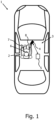
- the Figure 1 shows a top view of a vehicle 1 with a device for classifying objects within an interior 3 of the vehicle 1 according to an embodiment of the invention.
- the vehicle 1 comprises a 3D image capture unit 4 which is set up to capture 3D images of a scene and a processing unit 5 coupled to the 3D image capture unit 4.
- the processing unit 5 is set up to receive the 3D images from the 3D image capture unit 4 and to process them further.
- the field of view 8 of the 3D image acquisition unit 4 is in the Fig.1 shown example is directed at the driver 2 of the vehicle 1. However, it can also be provided that the field of view 8 of the 3D image capture unit 4 covers the entire front row of the interior 3 or even the entire interior 3.
- the 3D image capture unit 4 is arranged, for example, on the roof module of the vehicle 1.
- Other advantageous locations for the 3D image capture device 4 are, for example, the infotainment cluster or the instrument cluster of the vehicle 1. Since the driver 2 interacts with these clusters, good image capture, in particular of the driver 2, can be ensured.
- a second 3D image capture unit 4 can also be provided which, for example, only monitors the passenger seat.
- the 3D image capture unit 4 comprises an illumination unit with which the scene is illuminated, a sensor which, for example, measures the runtime for each pixel of the sensor separately, and an optic which collects the light reflected from the environment and images the scene onto the sensor.
- the optic can in particular comprise a lens for collecting the light.
- the 3D image capture unit 4 can, for example, comprise an optical bandpass filter which only lets through the wavelength with which the illumination also works, thereby eliminating a large part of the disturbing background light.
- the illumination unit preferably works in the near infrared range (NIR).
- NIR near infrared range
- the Fig.1 The device shown can be supported by other systems.
- additional cameras such as RGB cameras or thermal imaging cameras as well as additional detection systems such as ultrasound systems or capacitive measuring systems can be provided.
- the Figure 2 shows a block diagram of a device for classifying objects within an interior 3 of a vehicle 1 according to a further embodiment of the invention.
- the 3D image capture unit 4 is particularly preferably designed as a three-dimensional camera system by means of which a runtime method for distance measurement can be carried out.
- the 3D image capture unit 4 is designed as a time-of-flight (TOF) camera, which comprises the lighting unit, at least one optical element, at least one optical sensor and corresponding electronics for control and evaluation.
- TOF time-of-flight
- the principle of the TOF camera is based on a time-of-flight method for measuring distance. For example, a vehicle interior 3 or a part of the vehicle interior 3 is illuminated using a light pulse generated by the lighting unit, in particular a laser diode, whereby the TOF camera measures the time for each pixel that the light takes to reach the object and back to the optical sensor. The time required is preferably proportional to the corresponding distance. The captured scene is imaged on the optical sensor and then evaluated accordingly.
- the TOF camera is very robust, adaptable and does not require calibration.
- a TOF camera will be used as in Fig.2 shown four raw images 10 are taken with different phases. From the raw images 10, a 2D intensity image 20 and a 3D depth map 30 of a scene are generated by means of the processing unit 5. In Fig.2 It is further shown that a reflectivity map 40 is generated from the 2D intensity image 20 and the 3D depth map 30 by means of the processing unit 5.
- the reflectivity map 40 as well as the 2D intensity image 20 and the 3D depth map 30 are used individually or in combination for object classification and gesture recognition. It is particularly advantageous if the reflective properties of the objects are used for classification using the reflectivity map 40. Since many objects have different reflectivities, the objects can be classified more precisely. If the objects are classified precisely, their movement within the scene can be better tracked, which enables precise gesture recognition.
- FIG. 3 a flow chart of a method for classifying objects within an interior 3 of a vehicle 1 according to a further embodiment of the invention is shown.
- the method begins with step 100 in which a 3D image capture unit 4 is provided, which is set up to capture 3D images of a scene.
- the 3D image capture unit 4 can in particular be a TOF camera.
- the TOF camera comprises an illumination unit with which the scene is illuminated, a sensor which, for example, measures the runtime for each pixel of the sensor separately and an optic which collects the light reflected from the environment and images the scene onto the sensor.
- the optic can in particular be a lens to collect the light.
- the TOF camera can include, for example, an optical bandpass filter that only lets through the wavelength that the lighting works with, thereby eliminating a large part of the disturbing background light.
- the lighting unit preferably works in the near infrared range (NIR).
- NIR near infrared range
- step 110 a processing unit is provided.
- the processing unit serves to receive and process the 3D images.
- step 120 3D images of a scene are captured.
- Each captured 3D image includes at least one 2D intensity image 20 and at least one 3D depth map 30 of the scene.
- step 130 the 2D intensity image 20 and the 3D depth map 30 are used to calculate a reflectivity map 40.
- the calculation of the reflectivity map 40 can be carried out using the processing unit.
- the processing unit is part of a driver assistance system which carries out the calculation of the reflectivity map 40.
- step 140 at least one object in the scene is classified based on its reflectivity.
- the classification can also be carried out using the processing device. If the object has been classified, people and in particular gestures of people can also be recognized.
Landscapes
- Engineering & Computer Science (AREA)
- Theoretical Computer Science (AREA)
- Physics & Mathematics (AREA)
- General Physics & Mathematics (AREA)
- Multimedia (AREA)
- Transportation (AREA)
- Mechanical Engineering (AREA)
- Combustion & Propulsion (AREA)
- Chemical & Material Sciences (AREA)
- Human Computer Interaction (AREA)
- Health & Medical Sciences (AREA)
- Computer Vision & Pattern Recognition (AREA)
- General Health & Medical Sciences (AREA)
- Psychiatry (AREA)
- Social Psychology (AREA)
- Software Systems (AREA)
- General Engineering & Computer Science (AREA)
- Image Analysis (AREA)
- Traffic Control Systems (AREA)
Description
- Die vorliegende Erfindung betrifft ein Verfahren zur Klassifizierung von Objekten innerhalb eines Innenraums eines Fahrzeugs.
- Auch betrifft die vorliegende Erfindung eine Vorrichtung zur Klassifizierung von Objekten innerhalb eines Innenraums eines Fahrzeugs.
- Des Weiteren betrifft die vorliegende Erfindung ein Fahrerassistenzsystem mit einer Vorrichtung zur Klassifizierung von Objekten innerhalb eines Innenraums eines Fahrzeugs.
- Auch betrifft die vorliegende Erfindung ein Computerprogrammprodukt, umfassend Befehle, die bei der Ausführung des Programms durch einen Computer diesen veranlassen, das Verfahren auszuführen.
- Die Automobilindustrie legt immer mehr Wert darauf, Fahrzeuginsassen und Fußgänger vor Schäden zu schützen und ein erhöhtes Sicherheitsniveau zu gewährleisten. Gleichzeitig erwarten die Kunden ein intuitives Benutzererlebnis während der Fahrt wie beispielsweise Interaktion mit Infotainment- und Verbindungsfunktionen in ihrem Fahrzeug. Es wird erwartet, dass allmählich höhere Grade der Fahrautomatisierung in Fahrzeugdesigns einbezogen werden. Auf dem Weg zu solch einem hoch automatisierten Fahren ist es wichtig zu wissen, was innerhalb eines Kraftfahrzeugs passiert. Moderne Fahrerassistenzsysteme (Advanced Driver Assistance System, ADAS) und möglicherweise in Zukunft autonome Fahrzeuge erfordern genaue Informationen über den Fokus des Fahrers und die Vorgänge im Fahrzeug. Beispielsweise wie abgelenkt ist der Fahrer oder kann der Fahrer antworten. Hier setzen Kamera-basierte Sensoranwendungen in der Kabine an. Sie erkennen das Verhalten des Fahrers und liefern diese Informationen an das Fahrerassistenzsystem, um entsprechend reagieren zu können.
- Bis zum Übergang von den Fähigkeiten der aktuellen Fahrerassistenzsystem-Implementierungen zu einem wirklich autonomen Betrieb ist jedoch noch viel zu tun. Ein wichtiger Teil dieses evolutionären Prozesses wird sein, wie nahtlos der Wechsel vom autonomen Modus in den manuellen Modus in bestimmten Szenarien durchgeführt werden kann. Um voll wirksam zu sein, muss diese Änderung auf unkomplizierte und benutzerfreundliche Weise vorgenommen werden. Das Fahrerassistenzsystem des Fahrzeugs erfordert fortlaufend Zugang zu genauen, sehr detaillierten Informationen über den biomechanischen und kognitiven Zustand des Fahrers. 3D-Kameras ermöglichen dabei völlig neue Mensch-Maschine-Schnittstellen-Konzepte und Benutzererlebnisse, beispielsweise die Gestenerkennung und die Steuerung von Infotainmentsystemen. Insassenüberwachung und Gestenerkennung ermöglichen dabei komfortable Anwendungen sowie personalisierte Sicherheitsfunktionen.
- Aus der
WO 2014/032822 A2 ist eine Vorrichtung zur Steuerung von Fahrzeugfunktionen bekannt. Die Vorrichtung weist zumindest ein Interface auf, mit dem ein Benutzer durch statische und/oder dynamische Benutzergesten interagiert. Zudem ist eine Detektionseinheit vorgesehen, die die statischen und dynamischen Benutzergesten erfasst. Des Weiteren wird mit einer Steuereinheit eine Benutzergeste erfasst und eine dementsprechende Fahrzeugfunktion angesteuert. Dabei kann die Detektionseinheit eine oder mehrere Kameras aufweisen, die insbesondere als TOF-Kameras ausgebildet sind. Mit diesen kann vorzugsweise die Bewegung eines Teils des Kopfes, insbesondere des Auges oder der Nase erkannt werden. Darüber hinaus ist die Detektionseinheit dazu ausgelegt, parallele Gesten eines Benutzers und/oder die Gesten von mehreren Personen gleichzeitig und/oder sequentiell zu erkennen. - Für die Überwachung des Fahrers, insbesondere für die Identifizierung von Gesten des Fahrers, ist eine Klassifikation der im Sichtbereich der Bilderfassungseinrichtung befindlichen Objekte von großer Bedeutung.
- Ausgehend von dem oben genannten Stand der Technik liegt der Erfindung somit die Aufgabe zugrunde, ein Verfahren, eine Vorrichtung, ein Fahrerassistenzsystem und ein Computerprogrammprodukt anzugeben, durch die die Klassifizierung von Objekten innerhalb eines Innenraums eines Fahrzeugs und das Erkennen von Personen und Gesten der Personen verbessert wird.
- Die Lösung der Aufgabe erfolgt erfindungsgemäß durch die Merkmale der unabhängigen Ansprüche. Vorteilhafte Ausgestaltungen der Erfindung sind in den Unteransprüchen angegeben.
- Erfindungsgemäß ist somit ein Verfahren zur Klassifizierung von Objekten innerhalb eines Innenraums eines Fahrzeugs angegeben mit folgenden Schritten: Bereitstellen zumindest einer 3D-Bilderfassungseinheit, die zum Erfassen von 3D-Bildern einer Szene eingerichtet ist, Bereitstellen zumindest einer mit der 3D-Bilderfassungsseinheit gekoppelten Verarbeitungseinheit, wobei die Verarbeitungseinheit derart eingerichtet ist, die 3D-Bilder von der 3D-Bilderfassungseinheit zu empfangen, Erfassen von 3D-Bildern einer Szene, wobei jedes der 3D-Bilder zumindest ein 2D-Intensitätsbild und zumindest eine 3D-Tiefenkarte der Szene umfasst, Berechnung einer Reflektivitätskarte aus dem zumindest einen 2D-Intensitätsbild und der zumindest einen 3D-Tiefenkarte mittels der Verarbeitungseinheit, Klassifikation zumindest eines Objekts der Szene anhand seiner Reflektivität.
- Grundidee der vorliegenden Erfindung ist es also, eine Reflektivitätskarte auf der Grundlage von einem 2D-Intensitätsbild und einer 3D-Tiefenkarte zu erzeugen. Dabei werden das 2D-Intensitätsbild und einer 3D-Tiefenkarte mittels einer 3D-Bilderfassungseinheit erfasst und mittels einer Verarbeitungseinheit weiterverarbeitet.
- Das 2D-Intensitätsbild ist ein Bild, bei dem die Signalstärke von der Objektreflexion und dem Objektabstand zu der Beleuchtung der 3D-Bilderfassungseinheit abhängig ist. Die Reflexionscharakteristik einer Oberfläche ist dabei proportional zur empfangenen Beleuchtungsstärke durch den Sensor und der Distanz zwischen Objekt und der Beleuchtungseinheit der 3D-Bilderfassungseinheit gemäß folgender Formel:

- Aus der empfangenen Beleuchtungsstärke durch den Sensor, der Distanz zwischen dem Objekt und der Beleuchtungseinheit und einem konstanten Faktor, lässt sich somit die Reflektivität des Objekts berechnen und für jedes 3D-Bild eine Reflektivitätskarte der Szene erstellen.
- In die Berechnung des konstanten Faktors gehen dabei verschiedene Faktoren ein. In einer Ausführungsform der Erfindung umfasst die 3D-Bilderfassungseinheit eine Beleuchtungseinheit, mit der die Szene beleuchtet wird, einen Sensor, der beispielsweise die Laufzeit für jeden Bildpunkt des Sensors separat misst, eine Optik die das von der Umgebung reflektierte Licht wieder einsammelt und die Szene auf den Sensor abbildet. Dabei kann die Optik insbesondere eine Linse zum Sammeln des Lichts umfassen. Des Weiteren kann die 3D-Bilderfassungseinheit beispielsweise einen optischen Bandpassfilter umfassen, der nur die Wellenlänge durchlässt, mit der auch die Beleuchtung arbeitet, wodurch ein großer Teil des störenden Hintergrundlichtes eliminiert wird. Bevorzugt arbeitet die Beleuchtungseinheit im nahen Infrarotbereich (NIR).
- Die Reflektivität des Objekts für die zuvor geschilderte Ausführungsform kann dann mittels der folgenden Formel berechnet werden:

- Ee, Sensor
- Empfangene Beleuchtungsstärke durch den Sensor
- d
- Distanz von Sensor zum Objekt
- F#
- Apparatur der Linse
- m
- Vergrößerung der Linse
- Ie, mod
- Beleuchtungsstärke der Beleuchtungseinheit
- Tfilter, λ
- Durchlässigkeit des Filters
- Tlens
- Durchlässigkeit der Linse
- Das Reflexionsvermögen von Objekten kann dabei zuverlässiger genutzt werden, als die Intensitätsverteilung der durch den Sensor empfangenen Beleuchtungsstärke, um Objekte zu klassifizieren. Die Objekte werden somit nach ihrem Reflexionsgrad klassifiziert.
- In einer vorteilhaften Ausgestaltung der Erfindung enthält der Schritt der Klassifizierung des Objekts den zusätzlichen Schritt des Erkennens zumindest einer Person und/oder zumindest einer Geste einer Person. Da beispielsweise die menschliche Haut ein lambertianisches Reflexionsvermögen von 30-35% im NIR-Bereich besitzt, können insbesondere Hautpartien einer Person besonders gut klassifiziert werden. Durch die Klassifikation dieser Hautpartien kann dann auch die Bewegung der Person und insbesondere die von der Person ausgeführten Gesten erkannt werden.
- In einer weiter vorteilhaften Ausgestaltung der Erfindung enthält der Schritt des Erfassens von 3D-Bildern einer Szene ein Erfassen einer Szene mittels eines Laufzeitverfahrens zur Distanzmessung. Mittels eines Laufzeitverfahrens zur Distanzmessung lassen sich auf einfache Weise mittels der 3D-Bilderfassungsseinheit ein 2D-Intensitätsbild und eine 3D-Tiefenkarte der Szene erstellen.
- Erfindungsgemäß ist außerdem eine Vorrichtung zur Klassifizierung von Objekten innerhalb eines Innenraums eines Fahrzeugs angegeben umfassend eine 3D-Bilderfassungseinheit und eine mit der 3D-Bilderfassungsseinheit gekoppelten Verarbeitungseinheit zur Durchführung des zuvor beschriebenen Verfahrens.
- In einer vorteilhaften Ausgestaltung der Erfindung ist die 3D-Bilderfassungseinheit derart in dem Innenraum des Fahrzeugs angeordnet, dass das Gesichtsfeld der 3D-Bilderfassungseinheit zumindest eine gesamte Vorderreihe des Fahrzeugs überdeckt. Dies ist besonders vorteilhaft da damit Objekt in der Nähe des Fahrers klassifiziert und insbesondere Gesten des Fahrers erkannt werden können.
- In einer weiter vorteilhaften Ausgestaltung der Erfindung ist die 3D-Bilderfassungseinheit an einem Dachmodul des Fahrzeugs angeordnet.
- Ein im Dachmodul des Fahrzeugs angeordnete 3D-Bilderfassungseinheit hat den Vorteil, dass ein großer Bereich des Innenraums des Fahrzeugs mittels der 3D-Bilderfassungseinheit ausgeleuchtet und erfasst werden kann. In einer Ausführungsform der Erfindung kann es auch vorgesehen sein, dass die 3D-Bilderfassungseinheit beispielsweise in einem Infotainment-Cluster oder einem Instrument-Cluster des Fahrzeugs angeordnet ist. Das Instrument-Cluster ist die zentrale Informationsstelle für den Fahrer. Es zeigt den Fahrzustand, also z. B. Geschwindigkeit, Motordrehzahl und Blinker des Fahrzeugs an. Durch die Interaktion des Fahrers mit dem Instrument-Cluster kann beispielsweise sehr genau eine Geste des Fahrers erkannt werden.
- In einer vorteilhaften Ausgestaltung der Erfindung ist die 3D-Bilderfassungseinheit eine Time-of-Flight Kamera. TOF-Kameras haben den Vorteil, dass sie sehr robust und anpassungsfähig sind und keine Kalibrierung benötigen.
- In einer vorteilhaften Ausgestaltung der Erfindung ist die 3D-Bilderfassungseinheit eine Stereokamera.
- Weiter ist erfindungsgemäß ein Fahrerassistenzsystem angegeben mit einer zuvor beschriebenen Vorrichtung zur Durchführung des zuvor beschriebenen Verfahrens.
- Erfindungsgemäß ist außerdem ein Computerprogrammprodukt angegeben, umfassend Befehle, die bei der Ausführung des Programms durch einen Computer diesen veranlassen, das zuvor beschriebene Verfahren auszuführen.
- Nachfolgend wird die Erfindung unter Bezugnahme auf die anliegende Zeichnung anhand bevorzugter Ausführungsformen näher erläutert.
- Es zeigt
- Fig. 1
- eine Draufsicht eines Fahrzeugs mit einer Vorrichtung zur Klassifizierung von Objekten innerhalb eines Innenraums des Fahrzeugs gemäß einem Ausführungsbeispiel der Erfindung,
- Fig. 2
- ein Blockdiagramm einer Vorrichtung zur Klassifizierung von Objekten innerhalb eines Innenraums eines Fahrzeugs gemäß einem weiteren Ausführungsbeispiel der Erfindung,
- Fig. 3
- ein Ablaufdiagramm eines Verfahrens zur Klassifizierung von Objekten innerhalb eines Innenraums eines Fahrzeugs gemäß einem weiteren Ausführungsbeispiel der Erfindung.
- Die
Figur 1 zeigt eine Draufsicht eines Fahrzeugs 1 mit einer Vorrichtung zur Klassifizierung von Objekten innerhalb eines Innenraums 3 des Fahrzeugs 1 gemäß einem Ausführungsbeispiel der Erfindung. Das Fahrzeug 1 umfasst dabei eine 3D-Bilderfassungseinheit 4 die zum Erfassen von 3D-Bildern einer Szene eingerichtet ist und eine mit der 3D-Bilderfassungsseinheit 4 gekoppelten Verarbeitungseinheit 5. Die Verarbeitungseinheit 5 ist dabei derart eingerichtet, die 3D-Bilder von der 3D-Bilderfassungseinheit 4 zu empfangen und weiterzuverarbeiten. Das Gesichtsfeld 8 der 3D-Bilderfassungsseinheit 4 ist in dem inFig. 1 gezeigten Beispiel auf den Fahrer 2 des Fahrzeugs 1 gerichtet. Es kann aber auch vorgesehen sein, dass das Gesichtsfeld 8 der 3D-Bilderfassungseinheit 4 die gesamte Vorderreihe des Innenraums 3 oder auch der den gesamten Innenraum 3 umfasst. Daher ist es besonders vorteilhaft, wenn die 3D-Bilderfassungseinheit 4 beispielsweise an dem Dachmodul des Fahrzeugs 1 angeordnet ist. Weitere vorteilhafte Plätze für die 3D-Bilderfassungseinrichtung 4 sind beispielsweise auch das Infotainment-Cluster oder das Instrument-Cluster des Fahrzeugs 1. Da der Fahrer 2 mit diesen Clustern agiert, kann eine gute Bilderfassung insbesondere des Fahrers 2 gewährleistet werden. Auch kann eine zweite 3D-Bilderfassungseinheit 4 vorgesehen sein, die beispielsweise nur den Beifahrersitz überwacht. - In einer Ausführungsform der Erfindung umfasst die 3D-Bilderfassungseinheit 4 eine Beleuchtungseinheit, mit der die Szene beleuchtet wird, einen Sensor, der beispielsweise die Laufzeit für jeden Bildpunkt des Sensors separat misst und eine Optik die das von der Umgebung reflektierte Licht wieder einsammelt und die Szene auf den Sensor abbildet. Dabei kann die Optik insbesondere eine Linse zum Sammeln des Lichts umfassen. Des Weiteren kann die 3D-Bilderfassungseinheit 4 beispielsweise einen optischen Bandpassfilter umfassen, der nur die Wellenlänge durchlässt, mit der auch die Beleuchtung arbeitet, wodurch ein großer Teil des störenden Hintergrundlichtes eliminiert wird. Bevorzugt arbeitet die Beleuchtungseinheit im nahen Infrarotbereich (NIR). Die in
Fig. 1 gezeigte Vorrichtung kann dabei durch weitere Systeme unterstützt werden. Um die Klassifizierung von Objekten weiter zu verbessern, können beispielsweise weitere Kameras wie z.B. RGB-Kameras oder Wärmebildkameras sowie weitere Detektionssysteme wie z.B. Ultraschallsysteme oder kapazitive Messsysteme vorgesehen sein. - Die
Figur 2 zeigt ein Blockdiagramm einer Vorrichtung zur Klassifizierung von Objekten innerhalb eines Innenraums 3 eines Fahrzeugs 1 gemäß einem weiteren Ausführungsbeispiel der Erfindung. Die 3D-Bilderfassungseinheit 4 ist besonders bevorzugt als dreidimensionales Kamerasystem ausgebildet, mittels dem ein Laufzeitverfahren zur Distanzmessung durchführbar ist. Beispielsweise ist die 3D-Bilderfassungseinheit 4 als eine Time-of-flight (TOF) Kamera ausgebildet, welche die Beleuchtungseinheit, zumindest ein optisches Element, zumindest einen optischen Sensor und eine entsprechende Elektronik zur Ansteuerung und Auswertung umfasst. - Das Prinzip der TOF-Kamera beruht auf einem Laufzeitverfahren zur Distanzmessung. Dazu werden beispielsweise ein Fahrzeuginnenraum 3 oder ein Teil des Fahrzeuginnenraums 3 mittels eines von der Beleuchtungseinheit, insbesondere einer Laserdiode, erzeugten Lichtpulses beleuchtet, wobei die TOF-Kamera für jeden Bildpunkt die Zeit misst, die das Licht bis zum Objekt und wieder zurück zum optischen Sensor benötigt. Vorzugsweise ist die benötigte Zeit proportional zur entsprechenden Distanz. Auf dem optischen Sensor wird die erfasste Szene, abgebildet und anschließend entsprechend ausgewertet. Die TOF-Kamera ist dabei sehr robust, anpassungsfähig und benötigt keine Kalibrierung.
- Wird in einer Ausführungsform eine TOF-Kamera verwendet werden wie in
Fig. 2 gezeigt vier Rohaufnahmen 10 mit unterschiedlichen Phasen aufgenommen. Aus den Rohaufnahmen 10 wird ein 2D-Intensitätsbild 20 und eine 3D-Tiefenkarte 30 einer Szene mittels der Verarbeitungseinheit 5 erzeugt. InFig. 2 ist weiter gezeigt, dass aus dem 2D-Intensitätsbild 20 und der 3D-Tiefenkarte 30 mittels der Verarbeitungseinheit 5 weiter eine Reflektivitätskarte 40 erzeugt wird. Die Reflektivitätskarte 40 sowie das 2D-Intensitätsbild 20 und die 3D-Tiefenkarte 30 werden einzelne oder auch in Kombination zur Objektklassifikation und zur Gestenerkennung eingesetzt. Dabei ist es besonders vorteilhaft, wenn die reflektiven Eigenschaften der Objekte zur Klassifikation mittels der Reflektivitätskarte 40 verwendet werden. Da viele Objekte unterschiedliche Reflektivitäten aufweisen, können die Objekte genauer klassifiziert werden. Sind die Objekte genau klassifiziert können auf deren Bewegung innerhalb der Szene besser verfolgt werden, wodurch eine genaue Gestenerkennung ermöglicht wird. - In
Figur 3 wird ein Ablaufdiagramm eines Verfahrens zur Klassifizierung von Objekten innerhalb eines Innenraums 3 eines Fahrzeugs 1 gemäß einem weiteren Ausführungsbeispiel der Erfindung gezeigt. - Das Verfahren beginnt mit Schritt 100 in dem eine 3D-Bilderfassungseinheit 4 bereitgestellt wird, die zum Erfassen von 3D-Bildern einer Szene eingerichtet ist. Die 3D-Bilderfassungseinheit 4 kann insbesondere eine TOF-Kamera sein. Die TOF-Kamera umfasst dabei eine Beleuchtungseinheit, mit der die Szene beleuchtet wird, einen Sensor, der beispielsweise die Laufzeit für jeden Bildpunkt des Sensors separat misst und eine Optik die das von der Umgebung reflektierte Licht wieder einsammelt und die Szene auf den Sensor abbildet. Dabei kann die Optik insbesondere eine Linse zum Sammeln des Lichts umfassen. Des Weiteren kann die TOF-Kamera beispielsweise einen optischen Bandpassfilter umfassen, der nur die Wellenlänge durchlässt, mit der auch die Beleuchtung arbeitet, wodurch ein großer Teil des störenden Hintergrundlichtes eliminiert wird. Bevorzugt arbeitet die Beleuchtungseinheit im nahen Infrarotbereich (NIR).
- In Schritt 110 wird eine Verarbeitungseinheit bereitgestellt. Die Verarbeitungseinheit dient dazu die 3D-Bilder zu empfangen und zu verarbeiten.
- In Schritt 120 werden 3D-Bilder einer Szene erfasst. Dabei umfasst jedes erfasste 3D-Bild zumindest ein 2D-Intensitätsbild 20 und zumindest eine 3D-Tiefenkarte 30 der Szene.
- In Schritt 130 werden das 2D-Intensitätsbild 20 und die 3D-Tiefenkarte 30 für die Berechnung einer Reflektivitätskarte 40 verwendet. Die Berechnung der Reflektivitätskarte 40 kann dabei mittels der Verarbeitungseinheit durchgeführt werden. Insbesondere kann es vorgesehen sein, dass die Verarbeitungseinheit Teil eines Fahrerassistenzsystems ist, welches die Berechnung der Reflektivitätskarte 40 durchführt.
- In Schritt 140 wird zumindest ein Objekt der Szene anhand seiner Reflektivität klassifiziert. Die Klassifizierung kann ebenfalls mittels der Verarbeitungsvorrichtung erfolgen. Wurde das Objekt klassifiziert können beispielsweise auch Personen und insbesondere Gesten von Personen erkannt werden.
-
- 1
- Fahrzeug
- 2
- Fahrer
- 3
- Innenraum
- 4
- Bilderfassungseinheit
- 5
- Verarbeitungseinheit
- 6
- Gesicht des Fahrers
- 7
- Hand des Fahrers
- 8
- Gesichtsfeld
- 10
- Rohdaten
- 20
- 2D-Intensitätsbild
- 30
- 3D-Tiefenkarte
- 40
- Reflektivitätskarte
- 50
- Objektklassifikation und Gestenerkennung
- 100
- Bereitstellen einer 3D-Bilderfassungseinheit
- 110
- Bereitstellen einer Verarbeitungseinheit
- 120
- Erfassen von 3D-Bildern einer Szene
- 130
- Berechnung Reflektivitätskarte aus 2D-Intensitätsbild und 3D-Tiefenkarte
- 140
- Klassifikation des Objekts
Claims (10)
- Verfahren zur Klassifizierung von Objekten (2) innerhalb eines Innenraums (3) eines Fahrzeugs (1) mit folgenden Schritten:Bereitstellen zumindest einer 3D-Bilderfassungseinheit (4), die zum Erfassen von 3D-Bildern einer Szene eingerichtet ist,Bereitstellen zumindest einer mit der 3D-Bilderfassungsseinheit (4) gekoppelten Verarbeitungseinheit (5), wobei die Verarbeitungseinheit (5) derart eingerichtet ist, die 3D-Bilder von der 3D-Bilderfassungseinheit (4) zu empfangen, gekennzeichnet durch die weiteren Schritte:Erfassen von 3D-Bildern einer Szene, wobei jedes der 3D-Bilder zumindest ein 2D-Intensitätsbild und zumindest eine 3D-Tiefenkarte der Szene umfasst,Berechnung einer Reflektivitätskarte aus dem zumindest einen 2D-Intensitätsbild und der zumindest einen 3D-Tiefenkarte mittels der Verarbeitungseinheit (5),Klassifikation zumindest eines Objekts (2) der Szene anhand seiner Reflektivität basierend auf der Reflektivitätskarte.
- Verfahren nach Anspruch 1, dadurch gekennzeichnet, dass
der Schritt der Klassifizierung des Objekts (2) den zusätzlichen Schritt des Erkennens zumindest einer Person und/oder zumindest einer Geste einer Person enthält. - Verfahren nach einem der vorherigen Ansprüche, dadurch gekennzeichnet, dass
der Schritt des Erfassens von 3D-Bildern einer Szene ein Erfassen einer Szene mittels eines Laufzeitverfahrens zur Distanzmessung enthält. - Vorrichtung zur Klassifizierung von Objekten (2) innerhalb eines Innenraums (3) eines Fahrzeugs (1) umfassend eine 3D-Bilderfassungseinheit (4) und eine mit der 3D-Bilderfassungsseinheit (4) gekoppelten Verarbeitungseinheit (5) zur Durchführung des Verfahrens nach einem der vorherigen Ansprüche.
- Vorrichtung nach Anspruch 4, dadurch gekennzeichnet, dass
die 3D-Bilderfassungseinheit (4) derart in dem Innenraum (3) des Fahrzeugs (1) angeordnet ist, dass das Gesichtsfeld (8) der 3D-Bilderfassungseinheit (4) zumindest eine gesamte Vorderreihe des Fahrzeugs (1) überdeckt. - Vorrichtung nach einem der Ansprüche 4 oder 5, dadurch gekennzeichnet, dass
die 3D-Bilderfassungseinheit (4) an einem Dachmodul des Fahrzeugs (1) angeordnet ist. - Vorrichtung nach einem der Ansprüche 4 bis 6, dadurch gekennzeichnet, dass
die 3D-Bilderfassungseinheit (4) eine Time-of-Flight Kamera ist. - Vorrichtung nach einem der Ansprüche 4 bis 6, dadurch gekennzeichnet, dass
die 3D-Bilderfassungseinheit (4) eine Stereokamera ist. - Fahrerassistenzsystem mit einer Vorrichtung nach einem der Ansprüche 4 bis 8 zur Durchführung des Verfahrens nach einem der Ansprüche 1 bis 3.
- Computerprogrammprodukt, umfassend Befehle, die bei der Ausführung des Programms durch einen Computer diesen veranlassen, das Verfahren nach einem der Ansprüche 1 bis 3 auszuführen.
Applications Claiming Priority (2)
| Application Number | Priority Date | Filing Date | Title |
|---|---|---|---|
| DE102019105778.7A DE102019105778A1 (de) | 2019-03-07 | 2019-03-07 | Verfahren zur Klassifizierung von Objekten innerhalb eines Kraftfahrzeugs |
| PCT/EP2020/055158 WO2020178137A1 (de) | 2019-03-07 | 2020-02-27 | Verfahren zur klassifizierung von objekten innerhalb eines kraftfahrzeugs |
Publications (2)
| Publication Number | Publication Date |
|---|---|
| EP3934929A1 EP3934929A1 (de) | 2022-01-12 |
| EP3934929B1 true EP3934929B1 (de) | 2024-09-04 |
Family
ID=69844774
Family Applications (1)
| Application Number | Title | Priority Date | Filing Date |
|---|---|---|---|
| EP20711507.2A Active EP3934929B1 (de) | 2019-03-07 | 2020-02-27 | Verfahren zur klassifizierung von objekten innerhalb eines kraftfahrzeugs |
Country Status (3)
| Country | Link |
|---|---|
| EP (1) | EP3934929B1 (de) |
| DE (1) | DE102019105778A1 (de) |
| WO (1) | WO2020178137A1 (de) |
Families Citing this family (2)
| Publication number | Priority date | Publication date | Assignee | Title |
|---|---|---|---|---|
| CN112969019B (zh) * | 2021-02-26 | 2023-08-08 | 深圳荆虹科技有限公司 | 一种tof模组及电子装置 |
| DE102023202806A1 (de) * | 2023-03-28 | 2024-10-02 | Continental Automotive Technologies GmbH | Verfahren zur bildverarbeitung für videokonferenzen |
Family Cites Families (6)
| Publication number | Priority date | Publication date | Assignee | Title |
|---|---|---|---|---|
| US8958911B2 (en) * | 2012-02-29 | 2015-02-17 | Irobot Corporation | Mobile robot |
| WO2014032822A2 (de) * | 2012-08-29 | 2014-03-06 | Johnson Controls Gmbh | Vorrichtung und verfahren zur steuerung von fahrzeugfunktionen durch detektion der interaktionen eines benutzers |
| US20150379362A1 (en) * | 2013-02-21 | 2015-12-31 | Iee International Electronics & Engineering S.A. | Imaging device based occupant monitoring system supporting multiple functions |
| US10230934B2 (en) * | 2013-06-14 | 2019-03-12 | Microsoft Tehcnology Licensing, Llc | Depth map correction using lookup tables |
| US9541415B2 (en) * | 2014-08-28 | 2017-01-10 | Telenav, Inc. | Navigation system with touchless command mechanism and method of operation thereof |
| DE102017214009B4 (de) * | 2017-08-10 | 2020-06-18 | Volkswagen Aktiengesellschaft | Verfahren und Vorrichtung zur Erkennung der Anwesenheit und/oder Bewegung eines Fahrzeuginsassen |
-
2019
- 2019-03-07 DE DE102019105778.7A patent/DE102019105778A1/de not_active Withdrawn
-
2020
- 2020-02-27 EP EP20711507.2A patent/EP3934929B1/de active Active
- 2020-02-27 WO PCT/EP2020/055158 patent/WO2020178137A1/de not_active Ceased
Also Published As
| Publication number | Publication date |
|---|---|
| EP3934929A1 (de) | 2022-01-12 |
| DE102019105778A1 (de) | 2020-09-10 |
| WO2020178137A1 (de) | 2020-09-10 |
Similar Documents
| Publication | Publication Date | Title |
|---|---|---|
| EP2478510B1 (de) | Verfahren und vorrichtung zur darstellung von hindernissen in einem einparkhilfesystem von kraftfahrzeugen | |
| EP1468401B1 (de) | Verfahren und vorrichtung zur erkennung von sichtbehinderungen bei bildsensorsystemen | |
| DE102011089195A1 (de) | Vorrichtung und Verfahren zur berührungslosen Erfassung von Gegenständen und/oder Personen und von diesen ausgeführten Gesten und/oder Bedienvorgängen | |
| DE102008046038A1 (de) | Anzeigevorrichtung | |
| DE112016006950T5 (de) | Anzeigesteuervorrichtung, Anzeigevorrichtung, fahrzeuginternes Anzeigesystem und Anzeigesteuerverfahren | |
| DE19826283B4 (de) | Verfahren zur Anzeige eines vor einem Kraftfahrzeug befindlichen Objektes, insbesondere eines vorausfahrenden Kraftfahrzeuges | |
| EP1339561A1 (de) | Anordnung und verfahren zur überwachung des umfelds eines fahrzeugs | |
| DE102008016215A1 (de) | Informationsvorrichtungsbediengerät | |
| DE112013003276T5 (de) | Objekterkennungseinrichtung | |
| DE112019007195T5 (de) | Anzeigesteuerungseinrichtung, anzeigesteuerungsverfahren und anzeigesteuerungsprogramm | |
| DE102009002979A1 (de) | Projektionsanzeigevorrichtung für Fahrzeuge | |
| EP3254172B1 (de) | Bestimmung einer position eines fahrzeugfremden objekts in einem fahrzeug | |
| WO2014032903A1 (de) | Verfahren und informationssystem zum filtern von objektinformationen | |
| WO2021023468A1 (de) | Vorrichtung und verfahren zur steuerung eines beifahrersitzes in einem fahrzeug | |
| DE102004034532B4 (de) | Verfahren zur Kennzeichnung von Bildinformationen in der Darstellung eines mit einer fahrzeugseitigen Bildaufnahmeeinrichtung aufgenommenen Nachtsichtbildes und zugehöriges Nachtsichtsystem | |
| WO2016067082A1 (de) | Verfahren und vorrichtung zur gestensteuerung in einem fahrzeug | |
| EP3727936A1 (de) | Verfahren zum erkennen von zumindest einem an einem kraftfahrzeug anliegenden objekt sowie steuervorrichtung und kraftfahrzeug | |
| EP3934929B1 (de) | Verfahren zur klassifizierung von objekten innerhalb eines kraftfahrzeugs | |
| DE102006008274B4 (de) | Kraftfahrzeug mit einer optischen Erfassungsvorrichtung und Verfahren zum Betreiben eines Kraftfahrzeugs | |
| DE102019004692B3 (de) | Vorrichtung und Verfahren zur Ermittlung von Bilddaten der Augen, von Augenpositionen und/oder einer Blickrichtung eines Fahrzeugnutzers in einem Fahrzeug | |
| DE102009014437A1 (de) | Objekterkennungssystem und -verfahren | |
| DE102009003220B4 (de) | Verfahren zur Kollisionswarnung sowie Kollisionswarneinrichtung | |
| DE102019206083A1 (de) | Verfahren zur optischen Inspektion, Kamerasystem und Fahrzeug | |
| DE102022132451A1 (de) | Vorrichtung zur erkennung einer benutzerposition mit wenigstens einem sensor und verfahren dazu | |
| DE102012200762A1 (de) | Verfahren und Fahrerassistenzsystem zur Signalisierung einer Verkehrssituation in einem Umfeld eines Fahrzeuges |
Legal Events
| Date | Code | Title | Description |
|---|---|---|---|
| STAA | Information on the status of an ep patent application or granted ep patent |
Free format text: STATUS: UNKNOWN |
|
| STAA | Information on the status of an ep patent application or granted ep patent |
Free format text: STATUS: THE INTERNATIONAL PUBLICATION HAS BEEN MADE |
|
| PUAI | Public reference made under article 153(3) epc to a published international application that has entered the european phase |
Free format text: ORIGINAL CODE: 0009012 |
|
| STAA | Information on the status of an ep patent application or granted ep patent |
Free format text: STATUS: REQUEST FOR EXAMINATION WAS MADE |
|
| 17P | Request for examination filed |
Effective date: 20210817 |
|
| AK | Designated contracting states |
Kind code of ref document: A1 Designated state(s): AL AT BE BG CH CY CZ DE DK EE ES FI FR GB GR HR HU IE IS IT LI LT LU LV MC MK MT NL NO PL PT RO RS SE SI SK SM TR |
|
| DAV | Request for validation of the european patent (deleted) | ||
| DAX | Request for extension of the european patent (deleted) | ||
| P01 | Opt-out of the competence of the unified patent court (upc) registered |
Effective date: 20230528 |
|
| RIC1 | Information provided on ipc code assigned before grant |
Ipc: G06V 40/10 20220101ALI20240214BHEP Ipc: G06V 40/20 20220101ALI20240214BHEP Ipc: G06V 20/64 20220101ALI20240214BHEP Ipc: G06V 20/59 20220101ALI20240214BHEP Ipc: G06V 10/60 20220101ALI20240214BHEP Ipc: B60K 35/28 20240101ALI20240214BHEP Ipc: B60K 35/10 20240101ALI20240214BHEP Ipc: G06T 7/593 20170101ALI20240214BHEP Ipc: G06T 7/20 20170101ALI20240214BHEP Ipc: G06F 3/01 20060101ALI20240214BHEP Ipc: B60K 35/00 20060101AFI20240214BHEP |
|
| GRAP | Despatch of communication of intention to grant a patent |
Free format text: ORIGINAL CODE: EPIDOSNIGR1 |
|
| STAA | Information on the status of an ep patent application or granted ep patent |
Free format text: STATUS: GRANT OF PATENT IS INTENDED |
|
| INTG | Intention to grant announced |
Effective date: 20240419 |
|
| GRAS | Grant fee paid |
Free format text: ORIGINAL CODE: EPIDOSNIGR3 |
|
| GRAA | (expected) grant |
Free format text: ORIGINAL CODE: 0009210 |
|
| STAA | Information on the status of an ep patent application or granted ep patent |
Free format text: STATUS: THE PATENT HAS BEEN GRANTED |
|
| AK | Designated contracting states |
Kind code of ref document: B1 Designated state(s): AL AT BE BG CH CY CZ DE DK EE ES FI FR GB GR HR HU IE IS IT LI LT LU LV MC MK MT NL NO PL PT RO RS SE SI SK SM TR |
|
| REG | Reference to a national code |
Ref country code: GB Ref legal event code: FG4D Free format text: NOT ENGLISH |
|
| REG | Reference to a national code |
Ref country code: CH Ref legal event code: EP |
|
| REG | Reference to a national code |
Ref country code: IE Ref legal event code: FG4D Free format text: LANGUAGE OF EP DOCUMENT: GERMAN |
|
| REG | Reference to a national code |
Ref country code: DE Ref legal event code: R096 Ref document number: 502020009100 Country of ref document: DE |
|
| REG | Reference to a national code |
Ref country code: LT Ref legal event code: MG9D |
|
| REG | Reference to a national code |
Ref country code: NL Ref legal event code: MP Effective date: 20240904 |
|
| PG25 | Lapsed in a contracting state [announced via postgrant information from national office to epo] |
Ref country code: NO Free format text: LAPSE BECAUSE OF FAILURE TO SUBMIT A TRANSLATION OF THE DESCRIPTION OR TO PAY THE FEE WITHIN THE PRESCRIBED TIME-LIMIT Effective date: 20241204 |
|
| PG25 | Lapsed in a contracting state [announced via postgrant information from national office to epo] |
Ref country code: GR Free format text: LAPSE BECAUSE OF FAILURE TO SUBMIT A TRANSLATION OF THE DESCRIPTION OR TO PAY THE FEE WITHIN THE PRESCRIBED TIME-LIMIT Effective date: 20241205 Ref country code: PL Free format text: LAPSE BECAUSE OF FAILURE TO SUBMIT A TRANSLATION OF THE DESCRIPTION OR TO PAY THE FEE WITHIN THE PRESCRIBED TIME-LIMIT Effective date: 20240904 Ref country code: FI Free format text: LAPSE BECAUSE OF FAILURE TO SUBMIT A TRANSLATION OF THE DESCRIPTION OR TO PAY THE FEE WITHIN THE PRESCRIBED TIME-LIMIT Effective date: 20240904 |
|
| PG25 | Lapsed in a contracting state [announced via postgrant information from national office to epo] |
Ref country code: BG Free format text: LAPSE BECAUSE OF FAILURE TO SUBMIT A TRANSLATION OF THE DESCRIPTION OR TO PAY THE FEE WITHIN THE PRESCRIBED TIME-LIMIT Effective date: 20240904 |
|
| PG25 | Lapsed in a contracting state [announced via postgrant information from national office to epo] |
Ref country code: LV Free format text: LAPSE BECAUSE OF FAILURE TO SUBMIT A TRANSLATION OF THE DESCRIPTION OR TO PAY THE FEE WITHIN THE PRESCRIBED TIME-LIMIT Effective date: 20240904 |
|
| PG25 | Lapsed in a contracting state [announced via postgrant information from national office to epo] |
Ref country code: HR Free format text: LAPSE BECAUSE OF FAILURE TO SUBMIT A TRANSLATION OF THE DESCRIPTION OR TO PAY THE FEE WITHIN THE PRESCRIBED TIME-LIMIT Effective date: 20240904 |
|
| PG25 | Lapsed in a contracting state [announced via postgrant information from national office to epo] |
Ref country code: ES Free format text: LAPSE BECAUSE OF FAILURE TO SUBMIT A TRANSLATION OF THE DESCRIPTION OR TO PAY THE FEE WITHIN THE PRESCRIBED TIME-LIMIT Effective date: 20240904 Ref country code: RS Free format text: LAPSE BECAUSE OF FAILURE TO SUBMIT A TRANSLATION OF THE DESCRIPTION OR TO PAY THE FEE WITHIN THE PRESCRIBED TIME-LIMIT Effective date: 20241204 |
|
| PG25 | Lapsed in a contracting state [announced via postgrant information from national office to epo] |
Ref country code: RS Free format text: LAPSE BECAUSE OF FAILURE TO SUBMIT A TRANSLATION OF THE DESCRIPTION OR TO PAY THE FEE WITHIN THE PRESCRIBED TIME-LIMIT Effective date: 20241204 Ref country code: PL Free format text: LAPSE BECAUSE OF FAILURE TO SUBMIT A TRANSLATION OF THE DESCRIPTION OR TO PAY THE FEE WITHIN THE PRESCRIBED TIME-LIMIT Effective date: 20240904 Ref country code: NO Free format text: LAPSE BECAUSE OF FAILURE TO SUBMIT A TRANSLATION OF THE DESCRIPTION OR TO PAY THE FEE WITHIN THE PRESCRIBED TIME-LIMIT Effective date: 20241204 Ref country code: LV Free format text: LAPSE BECAUSE OF FAILURE TO SUBMIT A TRANSLATION OF THE DESCRIPTION OR TO PAY THE FEE WITHIN THE PRESCRIBED TIME-LIMIT Effective date: 20240904 Ref country code: HR Free format text: LAPSE BECAUSE OF FAILURE TO SUBMIT A TRANSLATION OF THE DESCRIPTION OR TO PAY THE FEE WITHIN THE PRESCRIBED TIME-LIMIT Effective date: 20240904 Ref country code: GR Free format text: LAPSE BECAUSE OF FAILURE TO SUBMIT A TRANSLATION OF THE DESCRIPTION OR TO PAY THE FEE WITHIN THE PRESCRIBED TIME-LIMIT Effective date: 20241205 Ref country code: FI Free format text: LAPSE BECAUSE OF FAILURE TO SUBMIT A TRANSLATION OF THE DESCRIPTION OR TO PAY THE FEE WITHIN THE PRESCRIBED TIME-LIMIT Effective date: 20240904 Ref country code: ES Free format text: LAPSE BECAUSE OF FAILURE TO SUBMIT A TRANSLATION OF THE DESCRIPTION OR TO PAY THE FEE WITHIN THE PRESCRIBED TIME-LIMIT Effective date: 20240904 Ref country code: BG Free format text: LAPSE BECAUSE OF FAILURE TO SUBMIT A TRANSLATION OF THE DESCRIPTION OR TO PAY THE FEE WITHIN THE PRESCRIBED TIME-LIMIT Effective date: 20240904 |
|
| PG25 | Lapsed in a contracting state [announced via postgrant information from national office to epo] |
Ref country code: NL Free format text: LAPSE BECAUSE OF FAILURE TO SUBMIT A TRANSLATION OF THE DESCRIPTION OR TO PAY THE FEE WITHIN THE PRESCRIBED TIME-LIMIT Effective date: 20240904 |
|
| PG25 | Lapsed in a contracting state [announced via postgrant information from national office to epo] |
Ref country code: IS Free format text: LAPSE BECAUSE OF FAILURE TO SUBMIT A TRANSLATION OF THE DESCRIPTION OR TO PAY THE FEE WITHIN THE PRESCRIBED TIME-LIMIT Effective date: 20250104 Ref country code: PT Free format text: LAPSE BECAUSE OF FAILURE TO SUBMIT A TRANSLATION OF THE DESCRIPTION OR TO PAY THE FEE WITHIN THE PRESCRIBED TIME-LIMIT Effective date: 20250106 |
|
| PG25 | Lapsed in a contracting state [announced via postgrant information from national office to epo] |
Ref country code: RO Free format text: LAPSE BECAUSE OF FAILURE TO SUBMIT A TRANSLATION OF THE DESCRIPTION OR TO PAY THE FEE WITHIN THE PRESCRIBED TIME-LIMIT Effective date: 20240904 Ref country code: SM Free format text: LAPSE BECAUSE OF FAILURE TO SUBMIT A TRANSLATION OF THE DESCRIPTION OR TO PAY THE FEE WITHIN THE PRESCRIBED TIME-LIMIT Effective date: 20240904 |
|
| PG25 | Lapsed in a contracting state [announced via postgrant information from national office to epo] |
Ref country code: EE Free format text: LAPSE BECAUSE OF FAILURE TO SUBMIT A TRANSLATION OF THE DESCRIPTION OR TO PAY THE FEE WITHIN THE PRESCRIBED TIME-LIMIT Effective date: 20240904 |
|
| PG25 | Lapsed in a contracting state [announced via postgrant information from national office to epo] |
Ref country code: CZ Free format text: LAPSE BECAUSE OF FAILURE TO SUBMIT A TRANSLATION OF THE DESCRIPTION OR TO PAY THE FEE WITHIN THE PRESCRIBED TIME-LIMIT Effective date: 20240904 |
|
| PG25 | Lapsed in a contracting state [announced via postgrant information from national office to epo] |
Ref country code: SK Free format text: LAPSE BECAUSE OF FAILURE TO SUBMIT A TRANSLATION OF THE DESCRIPTION OR TO PAY THE FEE WITHIN THE PRESCRIBED TIME-LIMIT Effective date: 20240904 Ref country code: IT Free format text: LAPSE BECAUSE OF FAILURE TO SUBMIT A TRANSLATION OF THE DESCRIPTION OR TO PAY THE FEE WITHIN THE PRESCRIBED TIME-LIMIT Effective date: 20240904 |
|
| REG | Reference to a national code |
Ref country code: DE Ref legal event code: R097 Ref document number: 502020009100 Country of ref document: DE |
|
| PG25 | Lapsed in a contracting state [announced via postgrant information from national office to epo] |
Ref country code: DK Free format text: LAPSE BECAUSE OF FAILURE TO SUBMIT A TRANSLATION OF THE DESCRIPTION OR TO PAY THE FEE WITHIN THE PRESCRIBED TIME-LIMIT Effective date: 20240904 |
|
| PLBE | No opposition filed within time limit |
Free format text: ORIGINAL CODE: 0009261 |
|
| STAA | Information on the status of an ep patent application or granted ep patent |
Free format text: STATUS: NO OPPOSITION FILED WITHIN TIME LIMIT |
|
| 26N | No opposition filed |
Effective date: 20250605 |
|
| PG25 | Lapsed in a contracting state [announced via postgrant information from national office to epo] |
Ref country code: SE Free format text: LAPSE BECAUSE OF FAILURE TO SUBMIT A TRANSLATION OF THE DESCRIPTION OR TO PAY THE FEE WITHIN THE PRESCRIBED TIME-LIMIT Effective date: 20240904 |
|
| PG25 | Lapsed in a contracting state [announced via postgrant information from national office to epo] |
Ref country code: MC Free format text: LAPSE BECAUSE OF FAILURE TO SUBMIT A TRANSLATION OF THE DESCRIPTION OR TO PAY THE FEE WITHIN THE PRESCRIBED TIME-LIMIT Effective date: 20240904 |
|
| REG | Reference to a national code |
Ref country code: CH Ref legal event code: PL |
|
| PG25 | Lapsed in a contracting state [announced via postgrant information from national office to epo] |
Ref country code: LU Free format text: LAPSE BECAUSE OF NON-PAYMENT OF DUE FEES Effective date: 20250227 |
|
| PG25 | Lapsed in a contracting state [announced via postgrant information from national office to epo] |
Ref country code: CH Free format text: LAPSE BECAUSE OF NON-PAYMENT OF DUE FEES Effective date: 20250228 |
|
| GBPC | Gb: european patent ceased through non-payment of renewal fee |
Effective date: 20250227 |
|
| REG | Reference to a national code |
Ref country code: BE Ref legal event code: MM Effective date: 20250228 |
|
| PG25 | Lapsed in a contracting state [announced via postgrant information from national office to epo] |
Ref country code: GB Free format text: LAPSE BECAUSE OF NON-PAYMENT OF DUE FEES Effective date: 20250227 |
|
| PG25 | Lapsed in a contracting state [announced via postgrant information from national office to epo] |
Ref country code: BE Free format text: LAPSE BECAUSE OF NON-PAYMENT OF DUE FEES Effective date: 20250228 |
|
| PG25 | Lapsed in a contracting state [announced via postgrant information from national office to epo] |
Ref country code: IE Free format text: LAPSE BECAUSE OF NON-PAYMENT OF DUE FEES Effective date: 20250227 |
|
| PGFP | Annual fee paid to national office [announced via postgrant information from national office to epo] |
Ref country code: DE Payment date: 20260206 Year of fee payment: 7 |
|
| PG25 | Lapsed in a contracting state [announced via postgrant information from national office to epo] |
Ref country code: AT Free format text: LAPSE BECAUSE OF NON-PAYMENT OF DUE FEES Effective date: 20250227 |
|
| REG | Reference to a national code |
Ref country code: AT Ref legal event code: MM01 Ref document number: 1720035 Country of ref document: AT Kind code of ref document: T Effective date: 20250227 |
|
| PGFP | Annual fee paid to national office [announced via postgrant information from national office to epo] |
Ref country code: FR Payment date: 20260227 Year of fee payment: 7 |