EP3934570B1 - Systems and methods for controlling an oral irrigator - Google Patents
Systems and methods for controlling an oral irrigator Download PDFInfo
- Publication number
- EP3934570B1 EP3934570B1 EP20711060.2A EP20711060A EP3934570B1 EP 3934570 B1 EP3934570 B1 EP 3934570B1 EP 20711060 A EP20711060 A EP 20711060A EP 3934570 B1 EP3934570 B1 EP 3934570B1
- Authority
- EP
- European Patent Office
- Prior art keywords
- pump
- oral irrigator
- motor
- operational level
- standby mode
- Prior art date
- Legal status (The legal status is an assumption and is not a legal conclusion. Google has not performed a legal analysis and makes no representation as to the accuracy of the status listed.)
- Active
Links
Images

Classifications
-
- A—HUMAN NECESSITIES
- A61—MEDICAL OR VETERINARY SCIENCE; HYGIENE
- A61C—DENTISTRY; APPARATUS OR METHODS FOR ORAL OR DENTAL HYGIENE
- A61C17/00—Devices for cleaning, polishing, rinsing or drying teeth, teeth cavities or prostheses; Saliva removers; Dental appliances for receiving spittle
- A61C17/02—Rinsing or air-blowing devices, e.g. using fluid jets or comprising liquid medication
- A61C17/024—Rinsing or air-blowing devices, e.g. using fluid jets or comprising liquid medication with constant liquid flow
-
- A—HUMAN NECESSITIES
- A61—MEDICAL OR VETERINARY SCIENCE; HYGIENE
- A61C—DENTISTRY; APPARATUS OR METHODS FOR ORAL OR DENTAL HYGIENE
- A61C17/00—Devices for cleaning, polishing, rinsing or drying teeth, teeth cavities or prostheses; Saliva removers; Dental appliances for receiving spittle
- A61C17/02—Rinsing or air-blowing devices, e.g. using fluid jets or comprising liquid medication
-
- A—HUMAN NECESSITIES
- A61—MEDICAL OR VETERINARY SCIENCE; HYGIENE
- A61C—DENTISTRY; APPARATUS OR METHODS FOR ORAL OR DENTAL HYGIENE
- A61C17/00—Devices for cleaning, polishing, rinsing or drying teeth, teeth cavities or prostheses; Saliva removers; Dental appliances for receiving spittle
- A61C17/02—Rinsing or air-blowing devices, e.g. using fluid jets or comprising liquid medication
- A61C17/0202—Hand-pieces
-
- A—HUMAN NECESSITIES
- A61—MEDICAL OR VETERINARY SCIENCE; HYGIENE
- A61C—DENTISTRY; APPARATUS OR METHODS FOR ORAL OR DENTAL HYGIENE
- A61C17/00—Devices for cleaning, polishing, rinsing or drying teeth, teeth cavities or prostheses; Saliva removers; Dental appliances for receiving spittle
- A61C17/02—Rinsing or air-blowing devices, e.g. using fluid jets or comprising liquid medication
- A61C17/0205—Container filling apparatus
-
- A—HUMAN NECESSITIES
- A61—MEDICAL OR VETERINARY SCIENCE; HYGIENE
- A61C—DENTISTRY; APPARATUS OR METHODS FOR ORAL OR DENTAL HYGIENE
- A61C1/00—Dental machines for boring or cutting ; General features of dental machines or apparatus, e.g. hand-piece design
- A61C1/0007—Control devices or systems
Definitions
- the present disclosure is directed to systems and methods for electronic control of an operational level of an oral irrigator, particularly when flow from the oral irrigator is paused.
- US 2008/255498 A1 discloses a fluid delivery system comprising a control system configured to control flow of a solution into a solution delivery system.
- the control system controls the amount of pressure created by the pump by activating and/or deactivating the pump.
- the control system is optionally in communication with a pressure sensor, and may activate a pressure relief valve when over-pressurization is detected.
- US 2017/281312 A1 discloses a system for removing a foreign object from a root canal of a tooth by supplying fluid to the root canal.
- a system for controlling the operation of a fluid motion generator comprises a motor, a fluid source, a pump, a pressure sensor, a controller, a user interface and a handpiece.
- the controller uses pressure information from the pressure sensor to make adjustments to the motor and/or pump to provide a target pressure for the fluid delivered to the handpiece. For example, the controller may signal the motor to drive a piston pump more rapidly or more slowly, depending on the pressure information from the pressure sensor.
- Oral irrigators are sometimes designed with the ability to adjust the intensity of the water pressure to suit the needs of individual users. These irrigators use a mechanical intensity control system which works by diverting a portion of the outlet flow from the pump back to the inlet. The amount of return flow is controlled by the user, which in turn varies intensity at the nozzle. With this architecture the pump operates at a fixed voltage and only varies in speed in response to varying load conditions.
- pause control Another feature present in oral irrigators is pause control.
- This control provides the user with the ability to stop and start flow while holding the handle portion of the nozzle.
- this control works by operating a valve that simply blocks the flow of water from the pump to the nozzle. Without a secondary flow path, the pressure will rise in the pump potentially resulting in damage, thus a means of limiting pressure is required.
- a pressure relief valve is commonly implemented.
- the present disclosure is directed to systems and methods for electronic control of an operational level of an oral irrigator.
- the systems and methods of electronic control discussed herein pair methods of detecting pump load with an electronic pump control system.
- the electronic pump control system places the pump in a standby state when the load has exceeded a defined threshold and then returns the pump to its pre-load state when the load condition is within normal range.
- the present disclosure is directed to systems and methods for electronic control of an operational level of an oral irrigator, particularly when flow from the oral irrigator is paused.
- the systems and methods of electronic control disclosed herein pair methods of detecting pump load with an electronic pump control system.
- the electronic pump control system places the pump in a standby state when the load has exceeded a defined threshold and can then return the pump to its pre-load state when the load condition is again within normal range.
- Methods of detection may include motor current, water pressure, pump speed, etc.
- Methods of electronic pump control involve placing the oral irrigator in standby mode when the pause control feature is utilized.
- the electronic pump control system receives sensor data from one or more sensors; determines the operational level of the oral irrigator; and determines whether a key sensor indicator is above, below, or at a threshold. If the key sensor indicator is above a threshold, a controller changes the operational level to the standby mode. If the key sensor indicator is at or below the threshold, a controller maintains the current operational level. If the key sensor indicator is below the threshold, and the current operational level is the standby mode, a controller changes the operational level to a preset intensity operational level previously set before entering standby mode. Applicant has recognized and appreciated that it would be beneficial to provide an electronic method to control operational level where a mechanical relief valve is not required for the operation of pause control.
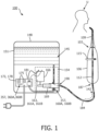
- FIG. 1 illustrates oral irrigator 100.
- Oral irrigator 100 includes irrigator tip 103 having handle portion 106 and nozzle 109.
- Irrigator tip 103 further includes channel 112 which extends within and through both tip 103 and handle portion 106. Channel 112 provides flow 142 of fluid 145 to user U.
- Oral irrigator 100 further includes housing 148 which contains reservoir 151, pump 154, controller 172, and power supply 178.
- Reservoir 151 contains a volume of fluid 145 which during operation of oral irrigator 100 is directed through irrigator tip 103 into the mouth of user U.
- Fluid 145 can be selected from, for example, water, a water-gas mixture, oral cleansing concentrate, standard or antiseptic (alcohol based) mouthwash, or any fluid with a viscosity low enough to proceed through channel 112.
- Pump 154 comprises pressure sensor 157, for example, a pressure transducer.
- Pressure sensor 157 is arranged to detect a first pressure 160A and a second pressure 160B.
- First pressure 160A is associated with a first state when first flow path is substantially aligned with channel 112.
- Second pressure 160B is associated with a closed state, when the first flow path is not substantially aligned with channel 112 and where flow 142 of fluid 145 through channel 112 is partially or completely restricted.
- the first pressure 160A and second pressure 160B are measured within the pump 154; however, it should be appreciated that first pressure 160A and second pressure 160B could be measured at any point along flow 142 spanning from the reservoir 151 to actuator 115. Accordingly, although pressure sensor 157 is illustrated within pump 154, it should be appreciated that pressure sensor 157 could be placed at any point along flow 142 spanning from the reservoir 151 to actuator 115.
- Pump 154 further includes motor 163, crank 166, and piston 169.
- Motor 163, crank 166, and piston 169 work in concert to create a pressurized environment that facilitates flow 142 from reservoir 151, through tether 184, into irrigator tip 103 and into user U's mouth.
- Tether 184 is a substantially hollow, flexible tube, having a first end 187 and a second end 190. First end 187 of tether 184 is fixedly secured to handle portion 106 of irrigator tip 103 and second end 190 of tether 184 is fixedly secured to pump 154.
- Tether 184 functions as a conduit through which flow 142 of fluid 145 precedes from reservoir 151 to irrigator tip 103 and into user U's mouth for cleaning.
- Actuator 115 can obstruct flow 142 and generate a back pressure, or build-up of pressure within the system which propagates along flow 142 back to pump 154.
- the actuator controls a pause control mechanism, where the flow 142 of fluid 145 through channel 112 is reduced or stopped when pause control is on and the system is paused, and the flow 142 of fluid 145 through channel 112 is resumed when pause control is off and the system is no longer paused.
- the actuator 115 can be any actuator or valve known in the art capable of at least partially altering flow 142, i.e., increasing or decreasing flow 142, e.g., a ball valve, a butterfly valve, a choke valve, a diaphragm or membrane valve, a gate valve, a globe valve, a knife valve, a needle valve, a pinch valve, a plug valve, a solenoid valve, a spool valve, a check valve, etc.
- a ball valve e.g., a ball valve, a butterfly valve, a choke valve, a diaphragm or membrane valve, a gate valve, a globe valve, a knife valve, a needle valve, a pinch valve, a plug valve, a solenoid valve, a spool valve, a check valve, etc.
- Controller 172 further comprises a processor and memory arranged to execute a series of non-transitory computer readable instructions to control the operation of motor 163. Controller 172 receives electrical power from power supply 178 and is arranged to control the speed and/or power of motor 163 by adjusting an operational current 181 of motor 163. Controller 172 includes controls 175. Controls 175 are utilized to turn oral irrigator 100 into an on or off state and/or alter the settings or modes of motor 163 thus changing the flow 142 of liquid 145 provided to user U.
- Controller 172 comprises load sensor 357.
- Load sensor 357 is arranged to detect a first load 360A, a second load 360B, and/or a first motor speed 161A and a second motor speed 161B, on motor 163.
- load sensor 357 may be a current sensor or a sensor arranged to measure motor speed or rotations, e.g., a tachometer.
- First load 360A is associated with a first state when the first flow path is substantially aligned with channel 112.
- Second load is associated with closed state, when the first flow path is not substantially aligned with channel 112 and where flow 142 of fluid 145 through channel 112 is partially or completely restricted creating a back pressure within the system sufficient to change the load on motor 163.
- first load 360A, second load 360B, first motor speed 161A, and second motor speed 161B are measured by load sensor 357 engaged to communicate with controller 172 and motor 163.
- Controller 172 e.g., receives first load 360A and second load 360B from load sensor 357 and adjusts the speed and/or power of motor 163, accordingly.
- first pressure 160A and second pressure 160B are measured by pressure sensor 157 engaged to communicate with controller 172 and motor 163.
- Controller 172 e.g., receives first pressure 160A and second pressure 160B from pressure sensor 157 and adjusts the speed and/or power of motor 163, accordingly.
- FIG. 2 is a flowchart which illustrates a method 500 for controlling an operational level of an oral irrigator 100.
- an operational level of the oral irrigator 100 is determined using the controller 172 of the oral irrigator 100.
- the operational level indicates the power level of the oral irrigator 172, including whether the oral irrigator 172 is powered on or off, whether it is in a low power standby mode, and the power or intensity level at which the oral irrigator 100 is operating.
- the power or intensity level of the oral irrigator 100 can be varied to increase the operational current 181, motor 163 speed, pressure 160A, 160B along the fluid channel 112, and the flow 142 of fluid 145 through the fluid channel 112.
- the controller 172 detects the power state and operational level of the oral irrigator 100.
- the controller 172 can be an electrical controller, and the controller 172 can include controls 175 which are analog or digital.
- the analog controls 175 and/or the digital controls 175 can determine when flow 142 is blocked and transition the oral irrigator 100 from its preset intensity operational level to standby mode, and back again when flow 142 is unblocked.
- the controller 172 receives sensor data from one or more of the sensors, including load sensor 357 and/or pressure sensor 157.
- the controller 172 is in communication with the load sensor 357 and the pressure sensor 157 and can detect the load 360A, 360B on the motor 163, motor speed 161A, 161B, and the pressure 160A, 160B along the fluid channel 112.
- the method can use sensor data from any type of sensor which can directly or indirectly detect a change in flow 142 along channel 112, including flow sensors, pressure detectors, load detectors, motor current detectors, motor speed detectors, or any other known sensors, or combinations of sensors and detection means.
- the controller 172 determines whether a key sensor indicator is above, below, or at a threshold level.
- the key sensor indicator is a sensor reading from the load sensor 357 and/or the pressure sensor 157, or any other sensor utilized by the system which provides information about the state of fluid 145 flow 142 through channel 112.
- the key sensor indicator can be a measure of flow 142, pressure 160A, 160B, electrical load 360A, 360B on the motor 163 of the pump 154, or speed 161A, 161B of the motor 163 of the pump 154 depending on an intensity of operational level of the oral irrigator 100.
- the key sensor indicator can measure a change in current 181 when the oral irrigator 100 is preset to a high intensity operational level.
- the key sensor indicator can measure a change in speed of the motor 163 when the oral irrigator 100 is preset to a low intensity operational level. For example, at lower intensity settings, first motor speed 161A and second motor speed 161B are measured by load sensor 357 engaged to communicate with controller 172 and motor 163.
- the key sensor indicator can be a measurement of the load on the motor 163 of the pump 154. The load on a motor 163 can be calculated using measured current. A current through the power supply of a motor 163 can be measured across a resistor. From the power supply current, a current through the motor 163 can be calculated. The current through the motor 163 can be divided by voltage or the pulse width modulation to determine the load on a motor 163.
- the threshold level can vary based on several factors.
- the threshold level can vary based on which sensor reading is used as the key sensor indicator. For example, if current is used as the key sensor indicator, then the threshold level will be a measure of current, for example in amperes. Similarly, if pressure is used as the key sensor indicator, then the threshold level will be a measure of pressure, for example an amount in pascals.
- the threshold also can vary based on the intensity level at which the oral irrigator 100 is operating or was previously set to before entering standby mode. For example, if the oral irrigator 100 has intensity levels 1-5, corresponding to increasing flow rates through channel 112, the threshold for each intensity level will be different.
- a user selectable intensity level can correspond with a motor voltage that determines the amount of flow and pressure (intensity level), and for greater intensity levels, the value of the threshold is greater.
- the load that triggers the pump to go into standby mode is sized appropriately for each intensity so that the user experience when pausing flow will be consistent regardless of the intensity level setting.
- the controller 172 changes the operational level of the oral irrigator 100 to a standby mode. If the key sensor indicator is at or below the threshold, the controller 172 does not change the operational level and the oral irrigator 100 remains at the current operational level. If, on the other hand, the key sensor indicator is below the threshold, and the current operational level of the oral irrigator 100 is standby mode, at step 530, the controller 172 will change the operational level of the oral irrigator 100 to a preset intensity level.
- the preset intensity is the operational level, for example, intensity level 1, intensity level 2 or intensity level 3, at which the oral irrigator 100 was operating before it entered standby mode.
- Standby mode is an operational level of the oral irrigator 100 where the oral irrigator 100 is operating at low power.
- the motor 163 When in standby mode, the motor 163 is not off. It is stalled in a low-power state within which the motor 163 can remain indefinitely without damage because the motor 163 does not exceed a tolerance temperature.
- the tolerance temperature is set so that the motor 163 does not overheat and to ensure reliable operation of the motor 163.
- the power must be sufficient to allow the pump to maintain a small amount of pressure in the system as long as a source of the blockage downstream (flow 142 through channel 112) is present, but not enough to overheat and damage the motor 163 or affect its reliability. This is key because it enables the system to detect when the blockage is removed and again resume normal operation of the pump thereafter.
- the oral irrigator systems utilizing method 500 will appear to turn off when the pause control mechanism is set to on (flow 142 through channel 112 is reduced or blocked) and eliminate the inherent noise and vibrations present in systems with pressure relief valves. Furthermore, as no pressure relief valve is required in the oral irrigator of method 500, pump efficiency may be optimized to deliver maximum output. As an example, under normal operation, current should be below the threshold level or value. However, when flow 142 is blocked when the pause control feature is utilized, the current will exceed this threshold triggering standby mode. The pump will remain in this state as long as the current is above a threshold.
- the pressure in the system Upon release of pause control, the pressure in the system will rapidly decrease resulting in less torque on the motor, and in turn cause the current to return normal range, signaling the controller 172 to deactivate standby mode. Once deactivated, the system will resume operation at the same intensity to which it was set prior to being paused.
Landscapes
- Health & Medical Sciences (AREA)
- Dentistry (AREA)
- Epidemiology (AREA)
- Life Sciences & Earth Sciences (AREA)
- Animal Behavior & Ethology (AREA)
- General Health & Medical Sciences (AREA)
- Public Health (AREA)
- Veterinary Medicine (AREA)
- Infusion, Injection, And Reservoir Apparatuses (AREA)
- Control Of Positive-Displacement Pumps (AREA)
- Control Of Non-Electrical Variables (AREA)
Applications Claiming Priority (2)
| Application Number | Priority Date | Filing Date | Title |
|---|---|---|---|
| US201962815578P | 2019-03-08 | 2019-03-08 | |
| PCT/EP2020/055349 WO2020182502A1 (en) | 2019-03-08 | 2020-02-28 | Systems and methods for controlling an oral irrigator |
Publications (3)
| Publication Number | Publication Date |
|---|---|
| EP3934570A1 EP3934570A1 (en) | 2022-01-12 |
| EP3934570B1 true EP3934570B1 (en) | 2023-06-07 |
| EP3934570C0 EP3934570C0 (en) | 2023-06-07 |
Family
ID=69810786
Family Applications (1)
| Application Number | Title | Priority Date | Filing Date |
|---|---|---|---|
| EP20711060.2A Active EP3934570B1 (en) | 2019-03-08 | 2020-02-28 | Systems and methods for controlling an oral irrigator |
Country Status (6)
| Country | Link |
|---|---|
| US (1) | US12414847B2 (enExample) |
| EP (1) | EP3934570B1 (enExample) |
| JP (1) | JP7309894B2 (enExample) |
| CN (1) | CN113543745B (enExample) |
| BR (1) | BR112021017705A2 (enExample) |
| WO (1) | WO2020182502A1 (enExample) |
Families Citing this family (5)
| Publication number | Priority date | Publication date | Assignee | Title |
|---|---|---|---|---|
| CN114271977A (zh) * | 2021-03-01 | 2022-04-05 | 程紫嫣 | 一种方便使用的口腔科便携式清洁喷洗装置 |
| CN114352496A (zh) * | 2021-12-28 | 2022-04-15 | 深圳市方利来科技有限公司 | 一种冲牙器动力机构 |
| CN114305772A (zh) * | 2022-01-28 | 2022-04-12 | 深圳市飞猫电器有限公司 | 一种冲牙器水泵连接结构及冲牙器 |
| KR20240146060A (ko) * | 2022-02-07 | 2024-10-07 | 파슈케 울트라소닉 엘엘씨 | 무선 배터리 구동 핸드헬드 초음파 치과 스케일링 시스템 |
| CN115778595B (zh) * | 2022-11-04 | 2026-01-06 | 上海飞象健康科技有限公司 | 冲牙器节流方法、节流系统及其使用方法 |
Family Cites Families (25)
| Publication number | Priority date | Publication date | Assignee | Title |
|---|---|---|---|---|
| JPS5591352A (en) * | 1978-12-29 | 1980-07-10 | Matsushita Electric Works Ltd | Mouth washer |
| DE3034930A1 (de) * | 1980-09-16 | 1982-04-22 | Kaltenbach & Voigt Gmbh & Co, 7950 Biberach | Vorrichtung zur versorgung zahnaerztlicher handstuecke mit betriebsmedien |
| US4669453A (en) | 1982-12-01 | 1987-06-02 | Snyder Laboratories, Inc. | Lavage system |
| EP1555954B1 (de) * | 2002-10-17 | 2010-04-14 | Braun GmbH | Munddusche und sprühdüse zur erzeugung eines flüssigkeitsstrahls sowie zahnreinigungssystem |
| EP1532940B1 (en) * | 2003-11-20 | 2011-08-24 | Cattani S.P.A. | A control device for fluid separators in dental aspiration plants |
| WO2007025244A2 (en) | 2005-08-25 | 2007-03-01 | Houle Philip R | Treatment systems for delivery of sensitizer solutions |
| US7670141B2 (en) * | 2006-07-07 | 2010-03-02 | Water Pik, Inc. | Oral irrigator |
| EP2541214A1 (en) | 2011-06-28 | 2013-01-02 | Braun GmbH | Personal care device and method for control thereof |
| KR101289954B1 (ko) * | 2011-11-11 | 2013-07-26 | 이한순 | 다인용 구강세정기 |
| CN204995600U (zh) * | 2013-03-14 | 2016-01-27 | 洁碧有限公司 | 冲洗装置 |
| US20140272769A1 (en) * | 2013-03-15 | 2014-09-18 | Water Pik, Inc. | Fluid activated switch for oral irrigator |
| RU2015144034A (ru) | 2013-03-15 | 2017-04-26 | Конинклейке Филипс Н.В. | Устройство для ухода за полостью рта, использующее импульсный поток текучей среды |
| EP3485843B1 (en) * | 2013-11-27 | 2020-05-13 | Water Pik, Inc. | Oral irrigator with tip release assembly |
| DE102013226637A1 (de) * | 2013-12-19 | 2015-06-25 | Meiko Maschinenbau Gmbh & Co. Kg | Reinigungsvorrichtung und Verfahren zur Reinigung von Reinigungsgut |
| CN203634323U (zh) * | 2013-12-27 | 2014-06-11 | 种磊 | 洗牙器 |
| WO2016097907A1 (en) * | 2014-12-16 | 2016-06-23 | Koninklijke Philips N.V. | Cleaning device with mechanical motion and plaque detection stream probe |
| GB2538309B (en) * | 2015-05-15 | 2017-09-20 | Dyson Technology Ltd | Cleaning appliance |
| CN204839802U (zh) * | 2015-05-21 | 2015-12-09 | 欧阳仪霏 | 一种牙套式牙齿清洁系统 |
| CN105213054A (zh) * | 2015-09-30 | 2016-01-06 | 深圳市前海安测信息技术有限公司 | 智能洗刷牙系统及方法 |
| US10806544B2 (en) * | 2016-04-04 | 2020-10-20 | Sonendo, Inc. | Systems and methods for removing foreign objects from root canals |
| US11873807B2 (en) * | 2016-07-27 | 2024-01-16 | Fna Group, Inc. | Pressure washer system |
| CN206183411U (zh) * | 2016-08-25 | 2017-05-24 | 刘诗锋 | 冲牙器的喷嘴连接结构 |
| GB2555620B (en) | 2016-11-04 | 2019-03-13 | Dyson Technology Ltd | Cleaning appliance |
| GB2559107B (en) * | 2016-11-04 | 2019-05-08 | Dyson Technology Ltd | Cleaning appliance |
| GB2555621B (en) * | 2016-11-04 | 2018-12-12 | Dyson Technology Ltd | Dental Cleaning Appliance |
-
2020
- 2020-02-28 EP EP20711060.2A patent/EP3934570B1/en active Active
- 2020-02-28 US US17/437,098 patent/US12414847B2/en active Active
- 2020-02-28 BR BR112021017705A patent/BR112021017705A2/pt not_active IP Right Cessation
- 2020-02-28 WO PCT/EP2020/055349 patent/WO2020182502A1/en not_active Ceased
- 2020-02-28 JP JP2021552993A patent/JP7309894B2/ja active Active
- 2020-02-28 CN CN202080019235.9A patent/CN113543745B/zh active Active
Also Published As
| Publication number | Publication date |
|---|---|
| JP7309894B2 (ja) | 2023-07-18 |
| US12414847B2 (en) | 2025-09-16 |
| US20220175502A1 (en) | 2022-06-09 |
| CN113543745B (zh) | 2024-07-09 |
| EP3934570A1 (en) | 2022-01-12 |
| BR112021017705A2 (pt) | 2021-11-16 |
| WO2020182502A1 (en) | 2020-09-17 |
| EP3934570C0 (en) | 2023-06-07 |
| JP2022524075A (ja) | 2022-04-27 |
| CN113543745A (zh) | 2021-10-22 |
Similar Documents
| Publication | Publication Date | Title |
|---|---|---|
| US12414847B2 (en) | Systems and methods for controlling an oral irrigator | |
| US7903383B2 (en) | Solenoid valve driving circuit and solenoid valve | |
| CA2606111A1 (en) | Controller for a motor and a method of controlling the motor | |
| CA2487835C (en) | Speed and fluid flow controller | |
| EP0720693B1 (en) | Flow-metered pumping with load compensation system and method | |
| KR101989211B1 (ko) | 진공 발생기 작동 방법 및 진공 발생 장치 | |
| AR025697A1 (es) | Surtidor de fluido con flujo de fluido estabilizado. | |
| JP2022524075A5 (enExample) | ||
| CA2605891A1 (en) | Controller for a motor and a method of controlling the motor | |
| ES2173845T3 (es) | Soporte logico para el control de los parametros operativos de un sistema quirurgico. | |
| WO2005026683A1 (ja) | リークテスタ | |
| US9463077B2 (en) | Dental scaler | |
| EP1234971A3 (en) | Control method | |
| US20120006415A1 (en) | Rinsing device and method for the operation thereof | |
| US20020064756A1 (en) | Dental handpiece for forming root canals | |
| FR2645213A1 (fr) | Groupe motopompe a capteurs de pression et de debit | |
| EP3398726A1 (en) | Trigger potentiometer | |
| EP2131260A1 (en) | Apparatus and method for automatic pump control | |
| EP3911267B1 (en) | Irrigator fluidic communication | |
| EP3086419B1 (en) | Wetting current sequencing for low current interface | |
| GB2609858A (en) | Dual mode negative pressure source operation for provision of negative pressure wound therapy | |
| RU2021129315A (ru) | Системы и способы управления ирригатором для полости рта | |
| JP4125649B2 (ja) | 流量計の電池電圧検出方法 | |
| WO2026073107A1 (en) | Method control with increased accuracy for oral health devices | |
| KR102221826B1 (ko) | 직류 모터의 제어 장치 및 방법 |
Legal Events
| Date | Code | Title | Description |
|---|---|---|---|
| STAA | Information on the status of an ep patent application or granted ep patent |
Free format text: STATUS: UNKNOWN |
|
| STAA | Information on the status of an ep patent application or granted ep patent |
Free format text: STATUS: THE INTERNATIONAL PUBLICATION HAS BEEN MADE |
|
| PUAI | Public reference made under article 153(3) epc to a published international application that has entered the european phase |
Free format text: ORIGINAL CODE: 0009012 |
|
| STAA | Information on the status of an ep patent application or granted ep patent |
Free format text: STATUS: REQUEST FOR EXAMINATION WAS MADE |
|
| 17P | Request for examination filed |
Effective date: 20211008 |
|
| AK | Designated contracting states |
Kind code of ref document: A1 Designated state(s): AL AT BE BG CH CY CZ DE DK EE ES FI FR GB GR HR HU IE IS IT LI LT LU LV MC MK MT NL NO PL PT RO RS SE SI SK SM TR |
|
| DAV | Request for validation of the european patent (deleted) | ||
| DAX | Request for extension of the european patent (deleted) | ||
| GRAP | Despatch of communication of intention to grant a patent |
Free format text: ORIGINAL CODE: EPIDOSNIGR1 |
|
| STAA | Information on the status of an ep patent application or granted ep patent |
Free format text: STATUS: GRANT OF PATENT IS INTENDED |
|
| INTG | Intention to grant announced |
Effective date: 20221125 |
|
| GRAS | Grant fee paid |
Free format text: ORIGINAL CODE: EPIDOSNIGR3 |
|
| GRAA | (expected) grant |
Free format text: ORIGINAL CODE: 0009210 |
|
| STAA | Information on the status of an ep patent application or granted ep patent |
Free format text: STATUS: THE PATENT HAS BEEN GRANTED |
|
| AK | Designated contracting states |
Kind code of ref document: B1 Designated state(s): AL AT BE BG CH CY CZ DE DK EE ES FI FR GB GR HR HU IE IS IT LI LT LU LV MC MK MT NL NO PL PT RO RS SE SI SK SM TR |
|
| REG | Reference to a national code |
Ref country code: GB Ref legal event code: FG4D |
|
| REG | Reference to a national code |
Ref country code: CH Ref legal event code: EP Ref country code: AT Ref legal event code: REF Ref document number: 1572548 Country of ref document: AT Kind code of ref document: T Effective date: 20230615 |
|
| REG | Reference to a national code |
Ref country code: DE Ref legal event code: R096 Ref document number: 602020011931 Country of ref document: DE |
|
| U01 | Request for unitary effect filed |
Effective date: 20230607 |
|
| U07 | Unitary effect registered |
Designated state(s): AT BE BG DE DK EE FI FR IT LT LU LV MT NL PT SE SI Effective date: 20230612 |
|
| REG | Reference to a national code |
Ref country code: LT Ref legal event code: MG9D |
|
| PG25 | Lapsed in a contracting state [announced via postgrant information from national office to epo] |
Ref country code: NO Free format text: LAPSE BECAUSE OF FAILURE TO SUBMIT A TRANSLATION OF THE DESCRIPTION OR TO PAY THE FEE WITHIN THE PRESCRIBED TIME-LIMIT Effective date: 20230907 Ref country code: ES Free format text: LAPSE BECAUSE OF FAILURE TO SUBMIT A TRANSLATION OF THE DESCRIPTION OR TO PAY THE FEE WITHIN THE PRESCRIBED TIME-LIMIT Effective date: 20230607 |
|
| PG25 | Lapsed in a contracting state [announced via postgrant information from national office to epo] |
Ref country code: RS Free format text: LAPSE BECAUSE OF FAILURE TO SUBMIT A TRANSLATION OF THE DESCRIPTION OR TO PAY THE FEE WITHIN THE PRESCRIBED TIME-LIMIT Effective date: 20230607 Ref country code: HR Free format text: LAPSE BECAUSE OF FAILURE TO SUBMIT A TRANSLATION OF THE DESCRIPTION OR TO PAY THE FEE WITHIN THE PRESCRIBED TIME-LIMIT Effective date: 20230607 Ref country code: GR Free format text: LAPSE BECAUSE OF FAILURE TO SUBMIT A TRANSLATION OF THE DESCRIPTION OR TO PAY THE FEE WITHIN THE PRESCRIBED TIME-LIMIT Effective date: 20230908 |
|
| PG25 | Lapsed in a contracting state [announced via postgrant information from national office to epo] |
Ref country code: SK Free format text: LAPSE BECAUSE OF FAILURE TO SUBMIT A TRANSLATION OF THE DESCRIPTION OR TO PAY THE FEE WITHIN THE PRESCRIBED TIME-LIMIT Effective date: 20230607 |
|
| PG25 | Lapsed in a contracting state [announced via postgrant information from national office to epo] |
Ref country code: IS Free format text: LAPSE BECAUSE OF FAILURE TO SUBMIT A TRANSLATION OF THE DESCRIPTION OR TO PAY THE FEE WITHIN THE PRESCRIBED TIME-LIMIT Effective date: 20231007 |
|
| PG25 | Lapsed in a contracting state [announced via postgrant information from national office to epo] |
Ref country code: SM Free format text: LAPSE BECAUSE OF FAILURE TO SUBMIT A TRANSLATION OF THE DESCRIPTION OR TO PAY THE FEE WITHIN THE PRESCRIBED TIME-LIMIT Effective date: 20230607 Ref country code: SK Free format text: LAPSE BECAUSE OF FAILURE TO SUBMIT A TRANSLATION OF THE DESCRIPTION OR TO PAY THE FEE WITHIN THE PRESCRIBED TIME-LIMIT Effective date: 20230607 Ref country code: RO Free format text: LAPSE BECAUSE OF FAILURE TO SUBMIT A TRANSLATION OF THE DESCRIPTION OR TO PAY THE FEE WITHIN THE PRESCRIBED TIME-LIMIT Effective date: 20230607 Ref country code: IS Free format text: LAPSE BECAUSE OF FAILURE TO SUBMIT A TRANSLATION OF THE DESCRIPTION OR TO PAY THE FEE WITHIN THE PRESCRIBED TIME-LIMIT Effective date: 20231007 Ref country code: CZ Free format text: LAPSE BECAUSE OF FAILURE TO SUBMIT A TRANSLATION OF THE DESCRIPTION OR TO PAY THE FEE WITHIN THE PRESCRIBED TIME-LIMIT Effective date: 20230607 |
|
| PG25 | Lapsed in a contracting state [announced via postgrant information from national office to epo] |
Ref country code: PL Free format text: LAPSE BECAUSE OF FAILURE TO SUBMIT A TRANSLATION OF THE DESCRIPTION OR TO PAY THE FEE WITHIN THE PRESCRIBED TIME-LIMIT Effective date: 20230607 |
|
| REG | Reference to a national code |
Ref country code: DE Ref legal event code: R097 Ref document number: 602020011931 Country of ref document: DE |
|
| U20 | Renewal fee for the european patent with unitary effect paid |
Year of fee payment: 5 Effective date: 20240229 |
|
| PLBE | No opposition filed within time limit |
Free format text: ORIGINAL CODE: 0009261 |
|
| STAA | Information on the status of an ep patent application or granted ep patent |
Free format text: STATUS: NO OPPOSITION FILED WITHIN TIME LIMIT |
|
| 26N | No opposition filed |
Effective date: 20240308 |
|
| PGFP | Annual fee paid to national office [announced via postgrant information from national office to epo] |
Ref country code: TR Payment date: 20240214 Year of fee payment: 5 |
|
| PG25 | Lapsed in a contracting state [announced via postgrant information from national office to epo] |
Ref country code: MC Free format text: LAPSE BECAUSE OF FAILURE TO SUBMIT A TRANSLATION OF THE DESCRIPTION OR TO PAY THE FEE WITHIN THE PRESCRIBED TIME-LIMIT Effective date: 20230607 |
|
| REG | Reference to a national code |
Ref country code: CH Ref legal event code: PL |
|
| PG25 | Lapsed in a contracting state [announced via postgrant information from national office to epo] |
Ref country code: CH Free format text: LAPSE BECAUSE OF NON-PAYMENT OF DUE FEES Effective date: 20240229 |
|
| PG25 | Lapsed in a contracting state [announced via postgrant information from national office to epo] |
Ref country code: CH Free format text: LAPSE BECAUSE OF NON-PAYMENT OF DUE FEES Effective date: 20240229 |
|
| PG25 | Lapsed in a contracting state [announced via postgrant information from national office to epo] |
Ref country code: IE Free format text: LAPSE BECAUSE OF NON-PAYMENT OF DUE FEES Effective date: 20240228 |
|
| PG25 | Lapsed in a contracting state [announced via postgrant information from national office to epo] |
Ref country code: IE Free format text: LAPSE BECAUSE OF NON-PAYMENT OF DUE FEES Effective date: 20240228 |
|
| U20 | Renewal fee for the european patent with unitary effect paid |
Year of fee payment: 6 Effective date: 20250228 |
|
| PG25 | Lapsed in a contracting state [announced via postgrant information from national office to epo] |
Ref country code: CY Free format text: LAPSE BECAUSE OF FAILURE TO SUBMIT A TRANSLATION OF THE DESCRIPTION OR TO PAY THE FEE WITHIN THE PRESCRIBED TIME-LIMIT; INVALID AB INITIO Effective date: 20200228 |
|
| PG25 | Lapsed in a contracting state [announced via postgrant information from national office to epo] |
Ref country code: HU Free format text: LAPSE BECAUSE OF FAILURE TO SUBMIT A TRANSLATION OF THE DESCRIPTION OR TO PAY THE FEE WITHIN THE PRESCRIBED TIME-LIMIT; INVALID AB INITIO Effective date: 20200228 |
|
| U20 | Renewal fee for the european patent with unitary effect paid |
Year of fee payment: 7 Effective date: 20260302 |
|
| PGFP | Annual fee paid to national office [announced via postgrant information from national office to epo] |
Ref country code: GB Payment date: 20260223 Year of fee payment: 7 |