EP3934397A1 - Radiator and electrical device - Google Patents
Radiator and electrical device Download PDFInfo
- Publication number
- EP3934397A1 EP3934397A1 EP20897364.4A EP20897364A EP3934397A1 EP 3934397 A1 EP3934397 A1 EP 3934397A1 EP 20897364 A EP20897364 A EP 20897364A EP 3934397 A1 EP3934397 A1 EP 3934397A1
- Authority
- EP
- European Patent Office
- Prior art keywords
- heat dissipation
- stress relieve
- radiator
- grooves
- groove
- Prior art date
- Legal status (The legal status is an assumption and is not a legal conclusion. Google has not performed a legal analysis and makes no representation as to the accuracy of the status listed.)
- Withdrawn
Links
Images

Classifications
-
- H—ELECTRICITY
- H05—ELECTRIC TECHNIQUES NOT OTHERWISE PROVIDED FOR
- H05K—PRINTED CIRCUITS; CASINGS OR CONSTRUCTIONAL DETAILS OF ELECTRIC APPARATUS; MANUFACTURE OF ASSEMBLAGES OF ELECTRICAL COMPONENTS
- H05K7/00—Constructional details common to different types of electric apparatus
- H05K7/20—Modifications to facilitate cooling, ventilating, or heating
- H05K7/2089—Modifications to facilitate cooling, ventilating, or heating for power electronics, e.g. for inverters for controlling motor
- H05K7/209—Heat transfer by conduction from internal heat source to heat radiating structure
-
- H—ELECTRICITY
- H05—ELECTRIC TECHNIQUES NOT OTHERWISE PROVIDED FOR
- H05K—PRINTED CIRCUITS; CASINGS OR CONSTRUCTIONAL DETAILS OF ELECTRIC APPARATUS; MANUFACTURE OF ASSEMBLAGES OF ELECTRICAL COMPONENTS
- H05K7/00—Constructional details common to different types of electric apparatus
- H05K7/20—Modifications to facilitate cooling, ventilating, or heating
- H05K7/2039—Modifications to facilitate cooling, ventilating, or heating characterised by the heat transfer by conduction from the heat generating element to a dissipating body
Definitions
- the present application relates to the technical field of electrical heat dissipation, and in particular to a radiator.
- the present application further relates to an electrical device including the above radiator.
- a radiator is generally provided for the heat dissipation of a heat-generating component with large heat or high heat flux.
- the radiator is generally composed of a heat dissipation substrate and a heat dissipation component mounted on the heat dissipation substrate, and the heat dissipation component is welded on the heat dissipation substrate.
- thermal expansion coefficients are different, and thermal deformation amounts are different.
- tensile stress is formed between the two materials, which causes deformation and increase of flatness of a heat dissipation functional surface of the heat dissipation component for enhanced heat dissipation which is in contact with a heat-generating device, increase of the heat dissipation resistance, and poor reliability of the radiator.
- An object according to the present application is to provide a radiator which has an improved heat dissipation effect. Another object according to the present application is to provide an electrical device including the above radiator.
- a radiator which includes a heat dissipation substrate and a heat dissipation component.
- a mounting position for mounting the heat dissipation component is provided on the heat dissipation substrate, a stress relieve groove is defined at the mounting position, and the heat dissipation component is welded to the mounting position.
- At least two stress relieve grooves are defined, and an island structure is formed between two adjacent stress relieve grooves.
- the stress relieve grooves are arranged in a grid shape, and the island structure is formed between the four stress relieve grooves.
- the stress relieve grooves are in a loop shape and nested one by one, and the island structure is formed between the two adjacent loop-shaped stress relieve grooves.
- the stress relieve grooves are respectively a first stress relieve groove and a second stress relieve groove intersecting with the first stress relieve groove, and the first stress relieve groove is parallel to an edge of the heat dissipation substrate.
- multiple second stress relieve grooves are defined, and two second stress relieve grooves are arranged crosswise.
- the mounting position is a welding groove recessed below a surface of the heat dissipation substrate.
- the heat dissipation component is a temperature equalizing plate.
- multiple mounting positions and multiple heat dissipation components are provided, and the heat dissipation components are in one-to-one correspondence with the mounting positions.
- all the heat dissipation components are mounted on the same mounting position, and the heat dissipation components are distributed in a length direction of the mounting position in sequence.
- the radiator further includes heat dissipation fins, the heat dissipation fins and the heat dissipation components are respectively distributed on two opposite sides of the heat dissipation substrate, and at least one set of heat dissipation fins is provided.
- An electrical device includes a radiator and a heat-generating device mounted on the radiator, wherein the radiator is the radiator according to any one of the above.
- the radiator according to the present application includes the heat dissipation substrate and the heat dissipation component.
- the mounting position for mounting the heat dissipation component is provided on the heat dissipation substrate, the stress relieve groove is defined at the mounting position, and the heat dissipation component is welded to the mounting position.
- the heat dissipation substrate is isolated at the mounting position from a connecting position of the heat dissipation component; and by defining the stress relieve groove, the stress pulling caused by thermal deformation of two materials of the heat dissipation component and the radiator is reduced, the reliability of the heat dissipation component is improved, the heat dissipation effect of the radiator is ensured, and the service life of the heat dissipation component is prolonged.
- FIGS. 1 to 4 Reference numerals in FIGS. 1 to 4 are listed as follows: 1 heat dissipation component; 2 heat dissipation substrate; 3 mounting position; 4 stress relieve groove; 4-1 first stress relieve groove; 4-2 second stress relieve groove; 5 island structure.
- a core according to the present application is to provide a radiator which has an improved heat dissipation effect.
- Another core according to the present application is to provide an electrical device including the above radiator.
- FIGS. 1 to 4 Reference is made to FIGS. 1 to 4 .
- the radiator according to a specific embodiment of the present application includes a heat dissipation substrate 2 and a heat dissipation component 1.
- the heat dissipation substrate is made of aluminum alloy
- the heat dissipation component 1 is made of copper.
- the heat dissipation substrate and the heat dissipation component 1 may be made of other materials according to actual needs.
- the heat dissipation substrate preferably has an integrally formed structure.
- the heat dissipation component 1 may be a temperature equalizing plate.
- a mounting position 3 for mounting the heat dissipation component 1 is provided on the heat dissipation substrate 2, a stress relieve groove 4 is defined at the mounting position 3, and the heat dissipation component 1 is welded to the mounting position 3.
- the stress relieve groove 4 is defined on a welding surface of the heat dissipation substrate and the heat dissipation component 1.
- at least two stress relieve grooves 4 are defined, and an island structure 5 is formed between two adjacent stress relieve grooves 4.
- the stress relieve grooves 4 may have groove bodies arranged in parallel.
- the stress relieve grooves 4 may be directly defined in the welding surface of the heat dissipation substrate and the heat dissipation component 1.
- the groove bodies of all the stress relieve grooves 4 internally communicate with each other.
- the heat dissipation substrate 2 is isolated at the mounting position 3 from a connecting position of the heat dissipation component 1; and by defining the stress relieve grooves 4, an island structure 5 is formed between two adjacent stress relieve grooves 4, which reduces the stress pulling caused by thermal deformation of two materials of the heat dissipation component 1 and the radiator, relieves the local thermal deformation stress, improves the reliability of the heat dissipation component 1, ensures the heat dissipation effect of the radiator, and prolongs the service life of the heat dissipation component 1.
- the stress relieve grooves 4 are arranged in a grid shape, and the island structure 5 is formed between the four stress relieve grooves 4.
- the stress relieve grooves 4 arranged horizontally are equally spaced apart, and the stress relieve grooves 4 arranged longitudinally are equally spaced apart.
- the stress relieve grooves 4 divide the welding surface of the heat dissipation substrate 2 and the heat dissipation component 1 into multiple areas, so that each of the areas is separated from the thermal deformation of the entire radiator to form the island structure 5.
- the stress relieve grooves 4 are respectively a first stress relieve groove 4-1 and a second stress relieve groove 4-2, and the first stress relieve groove 4-1 is parallel to an edge of the heat dissipation substrate 2.
- the first stress relieve groove 4-1 has a groove body structure respectively parallel to a short side and a long side of the heat dissipation substrate 2.
- the second stress relieve groove 4-2 intersects with the first stress relieve groove 4-1, and an included angle is an acute angle.
- the included angle between the second stress relieve groove 4-2 and the first stress relieve groove 4-1 may be a right angle or an obtuse angle.
- the first stress relieve groove 4-1 may be connected to an end of the second stress relieve groove 4-2.
- second stress relieve grooves 4-2 are defined. Specifically, as shown in FIG. 3 , the second stress relieve grooves 4-2 may be arranged in parallel. Alternatively, an included angle between extension lines of two adjacent second stress relieve grooves 4-2 may be an acute angle, and the second stress relieve grooves 4-2 are not arranged crosswise in this case.
- the island structure 5 is defined by the first stress relieve grooves 4-1 and the second stress relieve grooves 4-2.
- multiple second stress relieve grooves 4-2 are defined, two second stress relieve grooves 4-2 may arranged crosswise, and an included angle between the crosswise second stress relieve grooves 4-2 may be an acute angle, a right angle or an obtuse angle.
- An internal space defined by the first stress relieve grooves 4-1 is divided into four independent island structures 5 by two second stress relieve grooves 4-2 internally arranged.
- one second stress relieve groove 4-2 may intersect with multiple first stress relieve grooves 4-1, or one of the second stress relieve grooves 4-2 may intersect with other second stress relieve grooves 4-2, or one first stress relieve groove 4-1 may intersect with multiple second stress relieve grooves 4-2.
- the two intersecting stress relieve grooves 4 may smoothly transition to each other, and the smooth transition may specifically be an arc transition, so as to reduce the stress concentration at corners of the stress relieve grooves 4.
- the stress relieve grooves 4 are in a loop shape and nested one by one, and the island structure 5 is formed between two adjacent loop-shaped stress relieve grooves 4.
- the stress relieve grooves 4 may be circular, elliptical or rectangular.
- the stress relieve grooves 4 are arranged concentrically.
- the mounting position 3 is a welding groove recessed below a surface of the heat dissipation substrate 2.
- the welding groove may be dispensed with, the heat dissipation component 1 is welded into the welding groove on the heat dissipation substrate, and a heat dissipation functional surface of the heat dissipation component 1 is on the same plane as the surface of the heat dissipation substrate.
- the welding method is soldering or the like, which is not specifically limited here.
- multiple heat dissipation components 1 are provided.
- multiple mounting positions 3 are provided, and the heat dissipation components 1 are in one-to-one correspondence with the mounting positions 3.
- the multiple mounting positions 3 are equally spaced apart.
- all the heat dissipation components 1 are mounted on the same mounting position 3, and the heat dissipation components 1 are distributed in a length direction of the mounting position 3 in sequence.
- the heat dissipation components 1 are equally spaced apart in the length direction of the mounting position 3.
- the radiator according to the present application further includes heat dissipation fins, the heat dissipation fins and the heat dissipation components 1 are respectively distributed on two opposite sides of the heat dissipation substrate 2, and at least one set of heat dissipation fins is provided. Specifically, two or three sets of heat dissipation fins may be provided, and the heat dissipation fins in each set are equally spaced apart.
- the radiator according to the present application has a simple implementation process and almost no increase in cost, and can be easily popularized.
- An electrical device includes a radiator and a heat-generating device mounted on the radiator, wherein the radiator is the radiator according to any one of the above. Since the specific structure of the radiator has been described above, the electrical device including the above radiator also has the above technical effects.
- the electrical device according to the present application may be an inverter or other electrical device.
Landscapes
- Engineering & Computer Science (AREA)
- Microelectronics & Electronic Packaging (AREA)
- Physics & Mathematics (AREA)
- Thermal Sciences (AREA)
- Cooling Or The Like Of Electrical Apparatus (AREA)
- Cooling Or The Like Of Semiconductors Or Solid State Devices (AREA)
Abstract
Description
- The present application claims the priority to
Chinese Patent Application No. 201922177965.9, titled "RADIATOR AND ELECTRICAL DEVICE", filed with the China National Intellectual Property Administration on December 6, 2019 - The present application relates to the technical field of electrical heat dissipation, and in particular to a radiator. The present application further relates to an electrical device including the above radiator.
- With the increasing integration degree of components, the integration degree of core components of an electrical device is becoming higher and higher, which leads to increase of loss and heat flux. A radiator is generally provided for the heat dissipation of a heat-generating component with large heat or high heat flux. The radiator is generally composed of a heat dissipation substrate and a heat dissipation component mounted on the heat dissipation substrate, and the heat dissipation component is welded on the heat dissipation substrate.
- However, due to different materials of the heat dissipation substrate and the heat dissipation component in the conventional technology, thermal expansion coefficients are different, and thermal deformation amounts are different. In the welding combination method, due to the different thermal deformation amounts, tensile stress is formed between the two materials, which causes deformation and increase of flatness of a heat dissipation functional surface of the heat dissipation component for enhanced heat dissipation which is in contact with a heat-generating device, increase of the heat dissipation resistance, and poor reliability of the radiator.
- Therefore, a technical problem urgently to be solved by those skilled in the art is how to improve the reliability of the radiator.
- An object according to the present application is to provide a radiator which has an improved heat dissipation effect. Another object according to the present application is to provide an electrical device including the above radiator.
- In order to achieve the above objects, a radiator is provided according to the present application, which includes a heat dissipation substrate and a heat dissipation component. A mounting position for mounting the heat dissipation component is provided on the heat dissipation substrate, a stress relieve groove is defined at the mounting position, and the heat dissipation component is welded to the mounting position.
- Preferably, at least two stress relieve grooves are defined, and an island structure is formed between two adjacent stress relieve grooves.
- Preferably, the stress relieve grooves are arranged in a grid shape, and the island structure is formed between the four stress relieve grooves.
- Preferably, the stress relieve grooves are in a loop shape and nested one by one, and the island structure is formed between the two adjacent loop-shaped stress relieve grooves.
- Preferably, the stress relieve grooves are respectively a first stress relieve groove and a second stress relieve groove intersecting with the first stress relieve groove, and the first stress relieve groove is parallel to an edge of the heat dissipation substrate.
- Preferably, multiple second stress relieve grooves are defined, and two second stress relieve grooves are arranged crosswise.
- Preferably, the mounting position is a welding groove recessed below a surface of the heat dissipation substrate.
- Preferably, the heat dissipation component is a temperature equalizing plate.
- Preferably, multiple mounting positions and multiple heat dissipation components are provided, and the heat dissipation components are in one-to-one correspondence with the mounting positions.
- Preferably, all the heat dissipation components are mounted on the same mounting position, and the heat dissipation components are distributed in a length direction of the mounting position in sequence.
- Preferably, the radiator further includes heat dissipation fins, the heat dissipation fins and the heat dissipation components are respectively distributed on two opposite sides of the heat dissipation substrate, and at least one set of heat dissipation fins is provided.
- An electrical device includes a radiator and a heat-generating device mounted on the radiator, wherein the radiator is the radiator according to any one of the above.
- In the above technical solution, the radiator according to the present application includes the heat dissipation substrate and the heat dissipation component. The mounting position for mounting the heat dissipation component is provided on the heat dissipation substrate, the stress relieve groove is defined at the mounting position, and the heat dissipation component is welded to the mounting position.
- It can be seen from the above description that, in the radiator according to the present application, by defining the stress relieve groove at the mounting position, for mounting the heat dissipation component, of the heat dissipation substrate, the heat dissipation substrate is isolated at the mounting position from a connecting position of the heat dissipation component; and by defining the stress relieve groove, the stress pulling caused by thermal deformation of two materials of the heat dissipation component and the radiator is reduced, the reliability of the heat dissipation component is improved, the heat dissipation effect of the radiator is ensured, and the service life of the heat dissipation component is prolonged.
- To describe the technical solutions in the embodiments of the present application or in the conventional technology more clearly, the accompanying drawings required for describing the embodiments or the conventional technology are briefly introduced hereinafter. Apparently, the accompanying drawings in the following description show merely the embodiments of the present application, and a person of ordinary skill in the art can derive other drawings from these accompanying drawings without creative efforts.
-
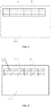
FIG. 1 is a schematic structural diagram of a radiator according to an embodiment of the preset application; -
FIG. 2 is a schematic structural diagram of a heat dissipation substrate according to an embodiment of the preset application; -
FIG. 3 is a schematic structural diagram of another heat dissipation substrate according to an embodiment of the preset application; and -
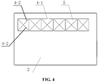
FIG. 4 is a schematic structural diagram of yet another heat dissipation substrate according to an embodiment of the preset application. - Reference numerals in
FIGS. 1 to 4 are listed as follows:1 heat dissipation component; 2 heat dissipation substrate; 3 mounting position; 4 stress relieve groove; 4-1 first stress relieve groove; 4-2 second stress relieve groove; 5 island structure. - A core according to the present application is to provide a radiator which has an improved heat dissipation effect. Another core according to the present application is to provide an electrical device including the above radiator.
- In order to provide those skilled in the art a better understanding of the technical solutions of the present application, the application will be further described in detail in conjunction with the drawings and specific embodiments.
- Reference is made to
FIGS. 1 to 4 . - In a specific embodiment, the radiator according to a specific embodiment of the present application includes a
heat dissipation substrate 2 and aheat dissipation component 1. Specifically, the heat dissipation substrate is made of aluminum alloy, and theheat dissipation component 1 is made of copper. Apparently, the heat dissipation substrate and theheat dissipation component 1 may be made of other materials according to actual needs. In order to reduce the assembly difficulty, the heat dissipation substrate preferably has an integrally formed structure. Specifically, theheat dissipation component 1 may be a temperature equalizing plate. - A
mounting position 3 for mounting theheat dissipation component 1 is provided on theheat dissipation substrate 2, a stress relievegroove 4 is defined at themounting position 3, and theheat dissipation component 1 is welded to themounting position 3. The stress relievegroove 4 is defined on a welding surface of the heat dissipation substrate and theheat dissipation component 1. Preferably, at least two stress relievegrooves 4 are defined, and anisland structure 5 is formed between two adjacent stress relievegrooves 4. Specifically, the stress relievegrooves 4 may have groove bodies arranged in parallel. Specifically, the stress relievegrooves 4 may be directly defined in the welding surface of the heat dissipation substrate and theheat dissipation component 1. Specifically, the groove bodies of all the stress relievegrooves 4 internally communicate with each other. - It can be seen from the above description that, in the radiator according to the specific embodiment of the present application, by defining the stress relieve
grooves 4 at themounting position 3, for mounting theheat dissipation component 1, of theheat dissipation substrate 2, theheat dissipation substrate 2 is isolated at themounting position 3 from a connecting position of theheat dissipation component 1; and by defining the stress relievegrooves 4, anisland structure 5 is formed between two adjacent stress relievegrooves 4, which reduces the stress pulling caused by thermal deformation of two materials of theheat dissipation component 1 and the radiator, relieves the local thermal deformation stress, improves the reliability of theheat dissipation component 1, ensures the heat dissipation effect of the radiator, and prolongs the service life of theheat dissipation component 1. - Preferably, as shown in
FIG. 2 , the stress relievegrooves 4 are arranged in a grid shape, and theisland structure 5 is formed between the four stress relievegrooves 4. Preferably, the stress relievegrooves 4 arranged horizontally are equally spaced apart, and the stress relievegrooves 4 arranged longitudinally are equally spaced apart. The stress relievegrooves 4 divide the welding surface of theheat dissipation substrate 2 and theheat dissipation component 1 into multiple areas, so that each of the areas is separated from the thermal deformation of the entire radiator to form theisland structure 5. - In a specific embodiment, the stress relieve
grooves 4 are respectively a first stress relieve groove 4-1 and a second stress relieve groove 4-2, and the first stress relieve groove 4-1 is parallel to an edge of theheat dissipation substrate 2. Specifically, the first stress relieve groove 4-1 has a groove body structure respectively parallel to a short side and a long side of theheat dissipation substrate 2. In a specific structure, the second stress relieve groove 4-2 intersects with the first stress relieve groove 4-1, and an included angle is an acute angle. Apparently, in specific implementation, the included angle between the second stress relieve groove 4-2 and the first stress relieve groove 4-1 may be a right angle or an obtuse angle. Specifically, the first stress relieve groove 4-1 may be connected to an end of the second stress relieve groove 4-2. - Multiple second stress relieve grooves 4-2 are defined. Specifically, as shown in
FIG. 3 , the second stress relieve grooves 4-2 may be arranged in parallel. Alternatively, an included angle between extension lines of two adjacent second stress relieve grooves 4-2 may be an acute angle, and the second stress relieve grooves 4-2 are not arranged crosswise in this case. Theisland structure 5 is defined by the first stress relieve grooves 4-1 and the second stress relieve grooves 4-2. - As shown in
FIG. 4 , multiple second stress relieve grooves 4-2 are defined, two second stress relieve grooves 4-2 may arranged crosswise, and an included angle between the crosswise second stress relieve grooves 4-2 may be an acute angle, a right angle or an obtuse angle. An internal space defined by the first stress relieve grooves 4-1 is divided into fourindependent island structures 5 by two second stress relieve grooves 4-2 internally arranged. By defining the two second stress relieve grooves 4-2, a stress relieve space is further increased, and the deformation caused by the inconsistent thermal expansion coefficients of theheat dissipation component 1 and theheat dissipation substrate 2 is reduced. - In the specific processing, one second stress relieve groove 4-2 may intersect with multiple first stress relieve grooves 4-1, or one of the second stress relieve grooves 4-2 may intersect with other second stress relieve grooves 4-2, or one first stress relieve groove 4-1 may intersect with multiple second stress relieve grooves 4-2.
- More specifically, the two intersecting stress relieve
grooves 4 may smoothly transition to each other, and the smooth transition may specifically be an arc transition, so as to reduce the stress concentration at corners of the stress relievegrooves 4. - In another specific embodiment, the stress relieve
grooves 4 are in a loop shape and nested one by one, and theisland structure 5 is formed between two adjacent loop-shaped stress relievegrooves 4. Specifically, the stress relievegrooves 4 may be circular, elliptical or rectangular. Preferably, the stress relievegrooves 4 are arranged concentrically. - In a specific embodiment, the mounting
position 3 is a welding groove recessed below a surface of theheat dissipation substrate 2. According to a design of an electrical system, the welding groove may be dispensed with, theheat dissipation component 1 is welded into the welding groove on the heat dissipation substrate, and a heat dissipation functional surface of theheat dissipation component 1 is on the same plane as the surface of the heat dissipation substrate. The welding method is soldering or the like, which is not specifically limited here. - In a specific embodiment, multiple
heat dissipation components 1 are provided. Specifically, multiple mountingpositions 3 are provided, and theheat dissipation components 1 are in one-to-one correspondence with the mounting positions 3. Preferably, the multiple mountingpositions 3 are equally spaced apart. - In another specific embodiment, all the
heat dissipation components 1 are mounted on thesame mounting position 3, and theheat dissipation components 1 are distributed in a length direction of the mountingposition 3 in sequence. Preferably, theheat dissipation components 1 are equally spaced apart in the length direction of the mountingposition 3. - The radiator according to the present application further includes heat dissipation fins, the heat dissipation fins and the
heat dissipation components 1 are respectively distributed on two opposite sides of theheat dissipation substrate 2, and at least one set of heat dissipation fins is provided. Specifically, two or three sets of heat dissipation fins may be provided, and the heat dissipation fins in each set are equally spaced apart. - Besides, the radiator according to the present application has a simple implementation process and almost no increase in cost, and can be easily popularized.
- An electrical device according to the present application includes a radiator and a heat-generating device mounted on the radiator, wherein the radiator is the radiator according to any one of the above. Since the specific structure of the radiator has been described above, the electrical device including the above radiator also has the above technical effects.
- Specifically, the electrical device according to the present application may be an inverter or other electrical device.
- The embodiments of the present application are described in a progressive manner, with an emphasis placed on explaining the difference between each embodiment and other embodiments. The same or similar parts among the embodiments can be referred to each other.
- According to the embodiments disclosed above, a person skilled in the art can implement or use the present application. Various modifications to the embodiments are obvious to the person skilled in the art, and general principles defined in the present application may be implemented in other embodiments without departing from the spirit or scope of the present application. Therefore, the present application shall not be limited to the embodiments described herein but have the widest scope that complies with the principle and novelty disclosed in this specification.
Claims (12)
- A radiator, comprising a heat dissipation substrate (2) and a heat dissipation component (1), wherein a mounting position (3) for mounting the heat dissipation component (1) is provided on the heat dissipation substrate (2), a stress relieve groove (4) is defined at the mounting position (3), and the heat dissipation component (1) is welded to the mounting position (3).
- The radiator according to claim 1, wherein at least two stress relieve grooves (4) are defined, and an island structure (5) is formed between two adjacent stress relieve grooves (4).
- The radiator according to claim 2, wherein the stress relieve grooves (4) are arranged in a grid shape, and the island structure (5) is formed between the four stress relieve grooves (4).
- The radiator according to claim 2, wherein the stress relieve grooves (4) are in a loop shape and nested one by one, and the island structure (5) is formed between two adjacent loop-shaped stress relieve grooves (4).
- The radiator according to claim 2, wherein the stress relieve grooves (4) are respectively a first stress relieve groove (4-1) and a second stress relieve groove (4-2) intersecting with the first stress relieve groove (4-1), and the first stress relieve groove (4-1) is parallel to an edge of the heat dissipation substrate (2).
- The radiator according to claim 5, wherein a plurality of second stress relieve grooves (4-2) are defined, and two of the plural second stress relieve grooves (4-2) are arranged crosswise.
- The radiator according to claim 1, wherein the mounting position (3) is a welding groove recessed below a surface of the heat dissipation substrate (2).
- The radiator according to claim 1, wherein the heat dissipation component (1) is a temperature equalizing plate.
- The radiator according to claim 1, wherein a plurality of mounting positions (3) and a plurality of heat dissipation components (1) are provided, and the plural heat dissipation components (1) are in one-to-one correspondence with the plural mounting positions (3).
- The radiator according to claim 9, wherein the plural heat dissipation components (1) are mounted on the same mounting position (3), and the plural heat dissipation components (1) are distributed in a length direction of the mounting position (3) in sequence.
- The radiator according to any one of claims 1 to 10, further comprising heat dissipation fins, wherein the heat dissipation fins and the heat dissipation component (1) are respectively distributed on two opposite sides of the heat dissipation substrate (2), and at least one set of heat dissipation fins is provided.
- An electrical device, comprising a radiator and a heat-generating device mounted on the radiator, wherein the radiator is the radiator according to any one of claims 1 to 11.
Applications Claiming Priority (2)
| Application Number | Priority Date | Filing Date | Title |
|---|---|---|---|
| CN201922177965.9U CN210959284U (en) | 2019-12-06 | 2019-12-06 | Radiator and electrical equipment |
| PCT/CN2020/132685 WO2021109964A1 (en) | 2019-12-06 | 2020-11-30 | Radiator and electrical device |
Publications (2)
| Publication Number | Publication Date |
|---|---|
| EP3934397A1 true EP3934397A1 (en) | 2022-01-05 |
| EP3934397A4 EP3934397A4 (en) | 2023-01-04 |
Family
ID=71383817
Family Applications (1)
| Application Number | Title | Priority Date | Filing Date |
|---|---|---|---|
| EP20897364.4A Withdrawn EP3934397A4 (en) | 2019-12-06 | 2020-11-30 | RADIATOR AND ELECTRICAL SYSTEM |
Country Status (4)
| Country | Link |
|---|---|
| US (1) | US12069841B2 (en) |
| EP (1) | EP3934397A4 (en) |
| CN (1) | CN210959284U (en) |
| WO (1) | WO2021109964A1 (en) |
Families Citing this family (2)
| Publication number | Priority date | Publication date | Assignee | Title |
|---|---|---|---|---|
| CN210959284U (en) | 2019-12-06 | 2020-07-07 | 阳光电源股份有限公司 | Radiator and electrical equipment |
| CN113241333A (en) * | 2021-04-30 | 2021-08-10 | 阳光电源股份有限公司 | Power device heat dissipation system, assembly method thereof and semiconductor equipment |
Family Cites Families (17)
| Publication number | Priority date | Publication date | Assignee | Title |
|---|---|---|---|---|
| JP2675173B2 (en) | 1990-03-02 | 1997-11-12 | 株式会社日立製作所 | Electronic device cooling system |
| JP4006173B2 (en) * | 2000-08-25 | 2007-11-14 | 三星エスディアイ株式会社 | Metal mask structure and manufacturing method thereof |
| JP2003163315A (en) | 2001-11-29 | 2003-06-06 | Denki Kagaku Kogyo Kk | module |
| DE102004035963A1 (en) * | 2004-07-23 | 2006-02-16 | Km Europa Metal Ag | cooling plate |
| JP4621531B2 (en) * | 2005-04-06 | 2011-01-26 | 株式会社豊田自動織機 | Heat dissipation device |
| JP4759384B2 (en) | 2005-12-20 | 2011-08-31 | 昭和電工株式会社 | Semiconductor module |
| JP2008294280A (en) * | 2007-05-25 | 2008-12-04 | Showa Denko Kk | Semiconductor device |
| DE102007063634B4 (en) * | 2007-11-26 | 2009-10-15 | Gesmex Gmbh | Method for connecting at least two heat exchanger plates |
| US8472193B2 (en) * | 2008-07-04 | 2013-06-25 | Kabushiki Kaisha Toyota Jidoshokki | Semiconductor device |
| CN201509363U (en) * | 2009-07-07 | 2010-06-16 | 中兴通讯股份有限公司 | A metal substrate assembled with a printed circuit board |
| US10126356B2 (en) | 2009-11-30 | 2018-11-13 | Essai, Inc. | Systems and methods for conforming test tooling to integrated circuit device with whirlwind cold plate |
| JP5349572B2 (en) * | 2011-04-18 | 2013-11-20 | 株式会社豊田自動織機 | Radiator and method of manufacturing radiator |
| CN102231944A (en) * | 2011-06-14 | 2011-11-02 | 华为技术有限公司 | Solder joint stress reduction structure and printed circuit board comprising same |
| US8488321B2 (en) * | 2011-10-10 | 2013-07-16 | Delphi Technologies, Inc. | Assembly for liquid cooling electronics by direct submersion into circulated engine coolant |
| JP2013115201A (en) | 2011-11-28 | 2013-06-10 | Toyota Industries Corp | Semiconductor device |
| JP6064886B2 (en) * | 2012-12-26 | 2017-01-25 | 株式会社豊田中央研究所 | Thermally conductive stress relaxation structure |
| CN210959284U (en) * | 2019-12-06 | 2020-07-07 | 阳光电源股份有限公司 | Radiator and electrical equipment |
-
2019
- 2019-12-06 CN CN201922177965.9U patent/CN210959284U/en active Active
-
2020
- 2020-11-30 US US17/440,696 patent/US12069841B2/en active Active
- 2020-11-30 WO PCT/CN2020/132685 patent/WO2021109964A1/en not_active Ceased
- 2020-11-30 EP EP20897364.4A patent/EP3934397A4/en not_active Withdrawn
Also Published As
| Publication number | Publication date |
|---|---|
| CN210959284U (en) | 2020-07-07 |
| US20220192048A1 (en) | 2022-06-16 |
| EP3934397A4 (en) | 2023-01-04 |
| US12069841B2 (en) | 2024-08-20 |
| WO2021109964A1 (en) | 2021-06-10 |
Similar Documents
| Publication | Publication Date | Title |
|---|---|---|
| EP1873827B1 (en) | Heat radiating device | |
| JP4867793B2 (en) | Semiconductor device | |
| CN107768328B (en) | A Power Device Realizing Double-sided Heat Dissipation and Pressure Equalization | |
| US9214405B2 (en) | Semiconductor module having heat dissipating portion | |
| US12069841B2 (en) | Radiator and electrical device | |
| EP3993587A1 (en) | Water-cooler heat dissipation device and electrical device | |
| US20210063090A1 (en) | Inverter And Heat Dissipation Device Thereof | |
| US20180151473A1 (en) | Lightweight liquid-cooling-plate assembly having plastic frame and heat dissipation system using same | |
| TWI620497B (en) | Folding-type heat dissipation device and method thereof | |
| JP5693395B2 (en) | Semiconductor device | |
| US9831153B1 (en) | Heat dissipating device | |
| JP2005150596A (en) | Semiconductor device and manufacturing method thereof | |
| KR20180002608U (en) | Cooling system using modular cooling apparatus | |
| EP4672884A1 (en) | HEAT DISSIPATION DEVICE | |
| US11917795B2 (en) | Heat sink structure | |
| CN104981130A (en) | Cooling fins and cooling modules | |
| CN219981405U (en) | Radiator and electrical equipment | |
| EP3909405B1 (en) | A heat sink for a remote radio unit | |
| JP5582070B2 (en) | Power semiconductor device and method for manufacturing power semiconductor device | |
| WO2016197789A1 (en) | Liquid-cooled heat sink, and processing and assembly method therefor | |
| CN220986457U (en) | Integrated radiator | |
| CN111403361A (en) | Heat sinks, controllers, air conditioners | |
| TWI905649B (en) | Heat dissipation device | |
| US20260129802A1 (en) | Air guide cover and electronic device | |
| KR102385112B1 (en) | Heat dissipation structure of FR4 PCB for power semiconductor device |
Legal Events
| Date | Code | Title | Description |
|---|---|---|---|
| STAA | Information on the status of an ep patent application or granted ep patent |
Free format text: STATUS: THE INTERNATIONAL PUBLICATION HAS BEEN MADE |
|
| PUAI | Public reference made under article 153(3) epc to a published international application that has entered the european phase |
Free format text: ORIGINAL CODE: 0009012 |
|
| STAA | Information on the status of an ep patent application or granted ep patent |
Free format text: STATUS: REQUEST FOR EXAMINATION WAS MADE |
|
| 17P | Request for examination filed |
Effective date: 20210928 |
|
| AK | Designated contracting states |
Kind code of ref document: A1 Designated state(s): AL AT BE BG CH CY CZ DE DK EE ES FI FR GB GR HR HU IE IS IT LI LT LU LV MC MK MT NL NO PL PT RO RS SE SI SK SM TR |
|
| A4 | Supplementary search report drawn up and despatched |
Effective date: 20221201 |
|
| RIC1 | Information provided on ipc code assigned before grant |
Ipc: H05K 7/20 20060101AFI20221125BHEP |
|
| DAV | Request for validation of the european patent (deleted) | ||
| DAX | Request for extension of the european patent (deleted) | ||
| STAA | Information on the status of an ep patent application or granted ep patent |
Free format text: STATUS: THE APPLICATION IS DEEMED TO BE WITHDRAWN |
|
| 18D | Application deemed to be withdrawn |
Effective date: 20230701 |