EP3934113B1 - Method for transmission on a plurality of frequency bands between two neighbouring devices of a network. - Google Patents
Method for transmission on a plurality of frequency bands between two neighbouring devices of a network. Download PDFInfo
- Publication number
- EP3934113B1 EP3934113B1 EP21181359.7A EP21181359A EP3934113B1 EP 3934113 B1 EP3934113 B1 EP 3934113B1 EP 21181359 A EP21181359 A EP 21181359A EP 3934113 B1 EP3934113 B1 EP 3934113B1
- Authority
- EP
- European Patent Office
- Prior art keywords
- node device
- frequency band
- interleaving
- message
- frequency bands
- Prior art date
- Legal status (The legal status is an assumption and is not a legal conclusion. Google has not performed a legal analysis and makes no representation as to the accuracy of the status listed.)
- Active
Links
- 230000005540 biological transmission Effects 0.000 title claims description 77
- 238000000034 method Methods 0.000 title claims description 60
- 238000004891 communication Methods 0.000 claims description 135
- 230000010354 integration Effects 0.000 claims description 12
- 238000004590 computer program Methods 0.000 claims description 4
- 239000012634 fragment Substances 0.000 description 42
- 239000000969 carrier Substances 0.000 description 20
- 230000008569 process Effects 0.000 description 10
- 230000004044 response Effects 0.000 description 10
- 239000003999 initiator Substances 0.000 description 9
- 238000013467 fragmentation Methods 0.000 description 8
- 238000006062 fragmentation reaction Methods 0.000 description 8
- 102100036958 Cytosolic Fe-S cluster assembly factor NUBP1 Human genes 0.000 description 7
- 230000005611 electricity Effects 0.000 description 7
- 238000012545 processing Methods 0.000 description 7
- 238000004364 calculation method Methods 0.000 description 5
- 239000000872 buffer Substances 0.000 description 4
- 230000011218 segmentation Effects 0.000 description 4
- 101710139687 Cytosolic Fe-S cluster assembly factor NUBP1 Proteins 0.000 description 3
- 238000006243 chemical reaction Methods 0.000 description 3
- 230000001427 coherent effect Effects 0.000 description 3
- 102100037091 Exonuclease V Human genes 0.000 description 2
- 101000881977 Homo sapiens Exonuclease V Proteins 0.000 description 2
- 230000006978 adaptation Effects 0.000 description 2
- 238000004422 calculation algorithm Methods 0.000 description 2
- 230000008859 change Effects 0.000 description 2
- 238000005265 energy consumption Methods 0.000 description 2
- 230000006870 function Effects 0.000 description 2
- 238000012544 monitoring process Methods 0.000 description 2
- 230000010363 phase shift Effects 0.000 description 2
- 238000005070 sampling Methods 0.000 description 2
- 238000000638 solvent extraction Methods 0.000 description 2
- 235000008694 Humulus lupulus Nutrition 0.000 description 1
- 230000008901 benefit Effects 0.000 description 1
- 230000015556 catabolic process Effects 0.000 description 1
- 238000000354 decomposition reaction Methods 0.000 description 1
- 230000001419 dependent effect Effects 0.000 description 1
- 238000013461 design Methods 0.000 description 1
- 238000010616 electrical installation Methods 0.000 description 1
- 238000005516 engineering process Methods 0.000 description 1
- 239000011159 matrix material Substances 0.000 description 1
- 230000007246 mechanism Effects 0.000 description 1
- 238000000926 separation method Methods 0.000 description 1
- 230000009897 systematic effect Effects 0.000 description 1
- 238000010200 validation analysis Methods 0.000 description 1
Images


Classifications
-
- H—ELECTRICITY
- H04—ELECTRIC COMMUNICATION TECHNIQUE
- H04B—TRANSMISSION
- H04B3/00—Line transmission systems
- H04B3/54—Systems for transmission via power distribution lines
-
- H—ELECTRICITY
- H04—ELECTRIC COMMUNICATION TECHNIQUE
- H04B—TRANSMISSION
- H04B3/00—Line transmission systems
- H04B3/54—Systems for transmission via power distribution lines
- H04B3/542—Systems for transmission via power distribution lines the information being in digital form
-
- H—ELECTRICITY
- H04—ELECTRIC COMMUNICATION TECHNIQUE
- H04B—TRANSMISSION
- H04B2203/00—Indexing scheme relating to line transmission systems
- H04B2203/54—Aspects of powerline communications not already covered by H04B3/54 and its subgroups
- H04B2203/5429—Applications for powerline communications
- H04B2203/5433—Remote metering
Definitions
- At least one embodiment of the present invention relates to a method for transmitting a message from a first node device to a second node device belonging to a network neighborhood of the first node device, said first and second node devices belonging to a network using power line communications. At least one embodiment of the present invention relates to a device implementing the method.
- Communications by carrier currents in line PLC are developing, in particular within the framework of power supply networks of the AMM type (abbreviation meaning "Automated Meter Management", in English).
- Communication networks are thus implemented in power supply networks for automated collection by a base node device (also called “data concentrator”) of the network, from smart electricity meters. , energy consumption reading data that said smart electricity meters are respectively responsible for monitoring.
- the G3-PLC communication standard is defined to allow the various node devices (in particular data concentrator and smart electricity meters) of such a network to communicate with each other.
- the standard is specified in the ITU-T G.9903 recommendation which describes in particular the physical layer (PHY) and the data link layer (DLL, acronym for “Data Link Layer”, in English) of the OSI model (acronym for “Open Systems Interconnection”.
- the G3-PLC standard is intended to be used in frequency bands ranging from 10 to 490 kHz. More particularly, it supports the following frequency bands: the CENELEC A frequency band, which goes approximately from 35 kHz to 91 kHz; the FCC frequency band, which ranges from approximately 150 kHz to 480 kHz; the ARIB frequency band, which goes approximately 150 kHz to 400 kHz; and the CENELEC B frequency band, which ranges from approximately 98 kHz to 122 kHz. These different frequency bands have different characteristics in terms of bit rate, range, and resistance to disturbers, in particular.
- An example of prior art can be found in US 2012/134395
- the G3-PLC standard allows the use of only one of said frequency bands for a given node device. More precisely, recent node devices can sometimes support several frequency bands, but not at the same time. A reconfiguration is then necessary to pass from a first frequency band to a second frequency band.
- a reconfiguration can prove to be particularly complex. For example, a counter device that has not been able to receive a message telling it to change frequency band may become unable to communicate with the data concentrator device with which it is associated, after the latter has been able to change frequency band.
- the frequency band for which the components of a network have been certified, may end up at the capacity limit, which hinders an increase in the number of exchanges in the network, for example to introduce new functionalities or even new application needs, for example.
- the present application discloses a method for transmitting data, in the form of messages, in a power line communication network, the method being executed in a first node device of said network configured to communicate in a plurality of disjoint frequency bands with a second node device of said network, the method comprising transmission of a message in a transmission mode using in parallel at least two disjoint frequency bands among said plurality of disjoint frequency bands, and the method being characterized in that the transmission of a message in a mode of transmission using in parallel at least two disjoint frequency bands comprises using a so-called extended frequency band m comprising at least two disjoint frequency bands among said plurality of disjoint frequency bands, each disjoint frequency band comprising a plurality of sub-carriers, the method further comprising a step to interleave data of a message to be transmitted adapted to a transmission of said data distributed over all of said sub-carriers.
- node device being configured to communicate in a plurality of disjoint frequency bands with a second node device of said network and to apply a transmission mode in, in parallel, at least two disjoint frequency bands among a plurality of disjoint frequency bands, the node device being characterized in that it is configured to transmit said message in a mode of transmission using at least two disjoint frequency bands in parallel by using a so-called “extended frequency band” frequency band comprising at least two disjoint frequency bands among said plurality of disjoint frequency bands, each disjoint frequency band comprising a plurality of sub-carriers, the node device comprising interleaving circuitry for interleaving data of a message to be transmitted adapted to transmission of said data distributed over all of said sub-carriers.
- the invention also relates to an in-line carrier current communication network comprising a plurality of node devices as previously described.
- the invention also relates to a computer program product comprising program code instructions for executing steps of the method described above when the program is executed by a processor, as well as an information storage medium comprising such a program product of computer.
- the communication network 120 relies on PLC line powerline communications.
- the communication network 120 is for example an electrical power supply network of the type AMM allowing a base node device (also called “data concentrator”) to collect, from smart electricity meters, energy consumption reading data from electrical installations that the smart electricity meters are respectively responsible for monitoring.
- the data concentrator and the smart electric meters are thus node devices of the communication network 120.
- the communication network 120 can comprise other node devices, for example installed at the level of electric transformers.
- the communication network 120 has a mesh structure.
- the mesh structure of the communication network 120 is represented schematically on the Fig. 1 thanks to arrows representing the communication links between two neighboring nodes and where node devices act as relays to increase the range of communications in the communication network 120.
- a single smart electricity meter thus potentially has several routes to reach the data concentrator, and vice versa.
- the present invention is therefore particularly suited to the context of G3-PLC technology.
- the communication network 120 thus comprises a plurality of node devices 130, 131, 132, 133, 134, 135, 136, 137, 138, 139.
- Each of the node devices of the communication network 120 is associated with a network neighborhood.
- node device 133 of the Fig. 1 is associated with a network neighborhood 110 encompassing node devices 130, 134, and 137.
- a signal or message broadcast by a node device such as, for example, node device 133, is generally not visible at any point of the communication network 120.
- Each node device transmitting signals or messages then has a network neighborhood, that is to say a subset of the communication network 120 in which any node device can intelligibly receive the signals or messages directly from the node device having broadcast these signals or messages.
- the network neighborhood corresponds to the range of the transmitted signals, according to predetermined transmission parameters (eg power, modulation and coding scheme, network topology, etc.) from the node device to the source of the signals and also potentially according to characteristics of the communication channel such as, for example, an attenuation, a noise level, an impedance.
- the communication network 120 is based on a reactive type routing protocol, such as, for example, the LOADng protocol (“Lightweight On-demand Ad hoc Distance-vector Routing Protocol—Next Generation” in English).
- LOADng protocol Lightweight On-demand Ad hoc Distance-vector Routing Protocol—Next Generation” in English.
- the reactive type of routing protocols are based on discoveries of routes on demand, each node device of the network then needing only to have knowledge of its own network neighborhood to route data in the communication network 120.
- RREQ Route Discovery Request
- RREQ Route Discovery request
- This route discovery request is received by each node device in the network neighborhood of said source node device.
- Each node device in the network neighborhood of said source node device relays, by broadcast, said copy of the request if said node device in question is not the destination node device.
- step-by-step broadcast several copies of the route discovery request are typically received by the destination node device, each of these copies having followed a different path in the communication network 120.
- routing tables stored in the node devices makes it possible to carry out point-to-point communications (“unicast” in English) between any pair of node devices of the communication network 120.
- Intermediate node devices therefore serve as relays when the node devices of said pair are not in the network neighborhood of each other, communications thus take place step by step, each node device relying on one of its own neighbors to forward messages to their respective recipients.
- the messages are transmitted in the form of modulated frames.
- a modulated frame is specifically addressed to a neighbor node device and it is correctly demodulated by the latter, said neighbor node device retransmits an acknowledgment ACK to the node device which sent said modulated frame to it.
- the acknowledgment ACK is transmitted on the same frequency band as the modulated frame with which said acknowledgment ACK is associated.
- Each frame transmitted in the form of modulated signals begins with a predefined preamble according to the modulation scheme according to which said signals have been modulated.
- the preamble is adapted to make it possible to synchronize reception on said frame, that is to say to be able to determine an effective frame start instant.
- the preamble typically comprises a plurality of successive copies of the same symbol.
- the actual content and the duration of the preamble are thus predefined and depend on the modulation scheme used.
- the preambles of multiple frames are identical when the same modulation scheme is applied, and differ otherwise.
- the applicable modulation schemes are preferably multi-carrier modulation schemes (respectively demodulation schemes) of the OFDM (Orthogonal Frequency Division Multiplex) type.
- the CENELEC A frequency band which ranges approximately from 35 kHz to 91 kHz
- the FCC frequency band which ranges from approximately 150 kHz to 480 kHz
- the ARIB frequency band which ranges from approximately 150 kHz to 400 kHz
- the CENELEC B frequency band which ranges from approximately 98 kHz to 122 kHz.
- a node device can simultaneously use several disjoint frequency bands to communicate with one or more of its neighbors, by applying a mechanism of suitable transmission.
- the ARIB and FCC frequency bands cannot be used simultaneously by the same node device, given that they overlap.
- the node devices 130, 131, 132, 133, 134, 135, 136, 137, 138, 139 are configured to communicate in several disjoint frequency bands. It is therefore important, for a given node device, to be able to determine which communication modes are supported by a node device in its network neighborhood.
- the terms "supported communication modes" designate one or more native communication modes of a node device, that is to say that the latter is capable of implementing due to its possible configurations, and also implies that this or these native communication modes can be used at a given time, taking into account the any disturbances that may exist. The disturbances may arise, for example, from a noisy environment.
- An exchange of messages according to a predefined protocol allows, for example, a first node device to obtain information regarding the communication capabilities of a second neighboring node device. For example, the first node device sends to the second neighboring node device a copy of a first message in each of the frequency bands in which it can communicate due to its configuration, and the neighboring node device is configured to recognize such a message and respond with a second message in each of the frequency bands in which it was able to receive it.
- the copies of the first message contain information according to which a channel estimate is requested from the neighboring node device, for the frequency band in which it received the message (request called “Tone Map” ).
- the information according to which a channel estimate is requested from the second neighboring node device by the first node device is then a Tone Map Request indicator of a frame control header defined according to ITU-T recommendation G9903.
- the second neighboring node device will respond to the Tone Map Request request by sending to the first node device, in each of the frequency bands in which it received a copy of the first message, a second message comprising information representative of at least one estimate channel in the form of a Tone Map Response data block as defined according to the ITU-T G9903 recommendation.
- the first device will therefore be able to know and store information about the frequency bands that it can use to communicate with the second neighboring node device.
- some of the node devices 130 to 139 are configured to operate at least one mode of communication using several disjoint frequency bands in parallel.
- the node device 133 for example, is configured to communicate in a single disjoint frequency band, in parallel in several disjoint frequency bands (multi-bands) or else in an extended frequency band.
- At least part of the node devices 130, 131, 132, 133, 134, 135, 136, 137, 138, 139 supporting modes of communication in several disjoint frequency bands also support a mode of communication in frequency band called “extended frequency band”.
- An extended frequency band advantageously comprises several disjoint frequency bands.
- an extended frequency band can comprise two, three or four disjoint frequency bands, for example, or even more.
- Each disjoint frequency band uses a plurality of sub-carriers.
- the extended frequency band can be defined as comprising the CENELEC A frequency band, the CENELEC B frequency band and the FCC band.
- the extended frequency band may be defined as comprising the CENELEC A frequency band, the CENELEC B frequency band and the ARIB frequency band.
- a first node device can therefore send a channel estimation request (request called a “TONE MAP” request) in the extended frequency band to determine whether a second neighboring node device supports communications in the extended frequency band.
- Fig. 2 illustrates a method of transmission in an extended frequency band according to a first embodiment.
- the illustrated method is executed in one, first, of the node devices of the communication network 120, configured so as to support an extended frequency band transmission mode, and which communicates with a second neighboring node device, also configured to communicate in an extended frequency band.
- the first node device in which the method is executed is, for example, the node device 133 which communicates with the second node device, neighbor, 134.
- the first and second node devices 133 and 134 are configured to communicate with each other according to at least one mode of communication in at least one frequency band. It is considered that the devices are then normally operational, at this stage, and that an exchange of messages can be initiated.
- the first node device 133 is configured during a step S21 to operate communications in an extended frequency band.
- This configuration is for example carried out by a writing, by a control module of the first node device 133, of an extended frequency band validation indicator.
- this indicator is a binary element (bit) positioned at “1” in a configuration register of the node device 133 which controls an interleaving of data to be transmitted according to an interleaving mode specific to transmission in an extended frequency band.
- the configuration of the first node device 133 in an extended frequency band communication mode can be carried out, for example, after the first node device 133 has sent a request for channel estimation, which request includes an indicator according to which an extended frequency band is concerned by this request, and that the second neighboring node device 134 has then responded to this request by indicating to the first node device 133 that it is indeed compatible with a communication in extended frequency band.
- the response from the second neighboring node device 134 is, for example, produced in the form of a message containing information representative of a channel estimate, on each of the frequency bands included in the extended frequency band as defined by the first device. node 133.
- the first node device 133 is natively designed to operate communications in extended frequency band, such as the frequency band is defined in the present description and no particular configuration of the first node device 133 is required after a phase of initialization following a power-up.
- the node device 133 is configured to communicate in extended frequency band at the end of the initialization step S20 and applies an extended frequency band communication mode, whether this required a particular configuration (selection of a mode of communication, for example) or even that this configuration is native, that is to say inherent to the design of the first node device 133 and to the various electronic circuits which compose it.
- the first node device 133 is configured to operate any exchange of messages or protocol signals intended to organize and manage the sharing of the network with other node devices. Such exchanges are thus intended to request access to the network, or even to record information relating to the communication capacities of neighboring node devices, such as the second node device 134, for example.
- a distribution of the data to be transmitted in extended frequency band, in each of the disjoint frequency bands of the defined extended band, is carried out during a step S22.
- the data is divided into different groups of data.
- the data of each of the different groups is intended to be transmitted in a band single frequency assigned to the group. It is considered here, without distinction, that a group of data is allocated to only one of the frequency bands comprised in the extended frequency band, or vice versa.
- the distributed data groups are sets of binary elements b1, b2, b3, b4, ..., bi, ... bn originating from a serial stream of binary elements.
- the data thus presented in the form of a serial stream comes from a convolutional encoder, such as a Viterbi encoder.
- a convolutional encoder such as a Viterbi encoder.
- the distribution of the data to be transmitted in an extended frequency band, into several groups, is carried out during a data interleaving step.
- the data interleaving step is performed by so-called “interleaver” circuitry.
- the interleaving is advantageously operated from an input interleaving table comprising a plurality of output interleaving tables, as explained later in the present description.
- the data grouped together (distributed) in as many output interleaving tables of the interleaver as there are disjoint frequency bands included in the extended frequency band are sent to modulators of the first node device 133 each operating in one of the different disjoint frequency bands.
- the data is transmitted to the second neighboring node device 134, in parallel and simultaneously, by the various modulators of the first node device 133.
- the second node device 134 configured for the reception of data in extended band, that is to say simultaneously in the same disjoint frequency bands as those used for transmission, operates in the opposite way.
- the second node device 134 demodulates the data received in each of the disjoint frequency bands, deinterleaves the data inversely to what is done by the interleaver of the first node device 133, then delivers a serial stream of bits destined for a Viterbi decoder, if applicable, of the second node device 134.
- the flowchart of the Fig.2 looping back to the start of step S22 illustrates a continuity of processing between successive data interleaving operations in step S22 and the transmission of these same data divided into groups, in an extended frequency band in step S23, c' that is to say in parallel on several disjoint frequency bands and by jointly using all the sub-carriers of each of the disjoint frequency bands of the extended band.
- the stream of binary elements at the input of the interleaver is processed by successive bits of binary elements. As bits are interleaved, previously interleaved bits are passed through the modulators.
- the first node device 133 in the event of a transmission problem, can be reconfigured in a communication mode distinct from a wideband communication mode, or even can transmit via a neighboring node device other than the second neighboring node device 134.
- the different steps for determining the quality of the transmission and/or reconfiguring the first node device 133 are not represented on the Fig. 2 , not being useful for understanding the invention.
- the distribution of the data to be transmitted in extended frequency band is cleverly carried out during an interleaving operation, so as, in particular, to simplify the adaptation of existing node devices to support transmission in extended frequency band.
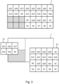
- Fig.3 represents an interleaving table T configured to perform data interleaving for communication in extended frequency band.
- the interleaving table T is obtained by concatenation of a first interleaving table T1 and a second interleaving table T2.
- the first interleaving table T is the input table of the interleaver used by the transmission method described on the Fig.2 and the interleaving tables T1 and T2 are output tables of the interleaver used for the transmission of the groups of distributed data to the various modulators, by the method executed.
- two modulators are used for the transmission of data in two frequency bands separate from the extended frequency band as defined.
- the interleaving tables T1 and T2 have respective dimensions (number of rows m i and of columns n i ) defined from the types of modulation used in each of the disjoint frequency bands of the extended frequency band.
- a first modulator uses a BPSK modulation (abbreviation for “Binary Phase Shift Keying”, in English) for the first frequency band and a second modulator uses a modulation of the QPSK type (abbreviation for “Quadrature Phase Shift Keying”) , in English).
- the interleaving table T1 corresponds to an interleaving table as defined, for example, according to the G3-PLC standard for BPSK modulation and its dimensions are defined by 2 rows and 3 columns.
- the interleaving table T2 corresponds to an interleaving table as defined, for example, according to the G3-PLC standard for QPSK modulation and its dimensions are defined by 4 rows and 5 columns.
- the dimensions of an interleaving table are defined so that the number of columns is equal to the number of subcarriers used in the frequency band used for data transmission and the number of rows depends the number of bits to interleave. This number of binary elements to be interleaved is therefore determined according to the number of binary elements coded by a symbol according to the type of modulation used, and by the number of sub-carriers used for the transmission of the symbols.
- the first interleaving table T is obtained by a concatenation of the second interleaving tables T1 and T2 which would be used for the interleaving of the data with a view to transmission in a single disjoint frequency band, respectively in BPSK for the second interleaving table T1 and in QPSK for the second interleaving table T2.
- Indices T1-11 to T1-13 index the different positions of the first line of the second interleaving table T1
- indices T1-21 to T1-23 index the different positions of the second line of the second interleaving table.
- indices T2-11 to T2-15 index the different positions of the first line of the second interleaving table T2
- indices T2-21 to T2-25 index the different positions of the second line of the second interleaving table T2
- indices T2-31 to T2-35 index the different positions of the third line of the second interleaving table T2
- indices T2-41 to T2-45 index the different positions of the fourth line of the second interleaving table T2.
- the aforementioned indices are not represented on the Fig.3 but can be used for a good understanding of the use of tables according to the embodiment described here.
- an index Ti [ m i , n i ] indexes, in the present description, a position at the m th line and the n th column of a table Ti.
- the previously cited indices therefore index the different positions of the interleaving table T obtained by concatenation of the interleaving tables T1 and T2, of the Fig. 3 to better illustrate the concatenation mode used.
- the concatenation of the second interleaving tables T1 and T2 is performed so that the table whose columns correspond to the lowest frequency subcarrier bands is located on the left.
- the second interleaving tables T1 and T2 are concatenated to define the first table T by matching the first line of the second interleaving table T1 with the first line of the second interleaving table T2, then the second line of the second interleaving table T1 with the second line of the second interleaving table T2.
- the definition of the first interleaving table T corresponds to the addition of the second interleaving table T1 and of the second interleaving table T2 to which is added a third interleaving table T' (represented in gray on the Fig. 3 ) so that the first interleaving table T has the same number of positions in each of its columns and in each of its rows.
- the positions included in the table T' are said to be “invalid” since, after an interleaving performed in the first interleaving table T, data (bits) could be moved to one of these positions.
- an interleaving operation in an interleaving table usually consists of shifting the content of each of the rows and columns a certain number of times by circular permutations of the binary elements contained in the positions of the table.
- Each row being conventionally shifted a number of times different from the other rows and each column being conventionally shifted a number of times different from the other columns.
- Binary elements b1 to b26 of a stream of binary elements are first "loaded” from left to right and from top to bottom into the first interleaving table T, prior to an interleaving operation, so that invalid positions are ignored.
- Binary element b1 is loaded in position T-11
- b2 is loaded in position T-12, ... b13 in position T-25, ... and b26 in position T-48.
- the invalid positions T-31, T-32, T-33, T-41, T-42 and T-43 of the first interleaving table T are ignored for the loading of bits b1 to b26.
- the first interleaving table T is thus obtained comprising the second interleaving tables T1 and T2, ready for an interleaving operation aimed at distributing the loaded data (bits b1 to b26) into several groups of data each assigned to a disjoint frequency band.
- the binary element b22 occupies for example the position occupied by the binary element b1 before the interleaving
- the binary element b24 occupies for example the position occupied by the binary element b2 before the interlacing
- the binary element b23 occupies for example the position occupied by the element b5 before the interlacing, ..., and so on.
- the interleaving having been carried out in entire rows and columns of the first interleaving table T, it follows that invalid positions may understand bits following interleaving. According to the embodiment, these elements are then moved to valid positions of the first interleaving table T.
- these movements are performed by traversing the invalid positions of the table T′ from top to bottom and from left to right. As soon as an invalid position comprises a binary element bi, the latter is moved to the first available valid position encountered by traversing the first interleaving table T from top to bottom and from left to right.
- each of the second interleaving tables T1 and T2 comprises a group of binary elements of the data divided into groups each corresponding to a disjoint frequency band included in the extended frequency band.
- the bits included in the second interleaving table T1 are transmitted to the first modulator with a view to transmission in BPSK in a first frequency band separate from the extended band
- the binary elements included in the second interleaving table T2 are transmitted to the second modulator with a view to transmission in QPSK in a second frequency band separate from the extended band.
- Each of the columns of the second interleaving tables corresponds to a sub-carrier of the frequency band allocated to the data group.
- the interleaving also operates a distribution of the data of each group on the various sub-carriers of the frequency band used for the transmission of the data of the group.
- the binary elements are respectively transmitted via serial streams to the modulators, via buffer memory zones (also called buffers or registers).
- the binary elements are in fact transmitted to input buffers respectively associated with the modulators, the input buffers of the modulators being directly the second interleaving tables T1 and T2.
- FIG.3 actually illustrates the division into groups of the first interleaving table T into two second interleaving tables T1 and T2 after the operations of interleaving and processing (moving) of the bits present at invalid positions, if any.
- This breakdown advantageously corresponds to the end of the interleaving useful for the distribution of the data to be transmitted in the extended frequency band, in the two disjoint frequency bands used according to the example described.
- the illustrated decomposition of the first interleaving table T into two second interleaving tables T1 and T2, at the end of the interleaving, constitutes an orientation of the data in the form of binary elements of each of the data groups (therefore of each of the second interleaving tables T1 and T2) to an electronic circuitry configured to modulate and transmit the binary elements.
- the electronic circuitry dedicated to each of the disjoint frequency bands notably comprises the modulator operating for transmission in this disjoint frequency band.
- the reasoning is similar as regards a distribution of data to be transmitted in three, four or even more disjoint frequency bands.
- the first interleaving table T (the largest) comprises as many second interleaving tables T1, T2, Ti as there are disjoint frequency bands included in the extended frequency band.
- the second interleaving tables T1, T2, Ti whose respective dimensions are defined according to the type of modulation used on each of the disjoint frequency bands included in the extended frequency band, are concatenated so that the table which includes the lowest sub-carriers is positioned on the left in the first interleaving table T, and the table which includes the highest sub-carriers is positioned on the right in the first interleaving table.
- Any second intermediate interleaving tables are arranged from left to right, in order of increasing frequency of the sub-carriers which they comprise.
- the first lines of each of the second tables T1, T2, Ti are aligned in the first upper line of the first interleaving table T.
- the matrix representation of the interleaving tables T, T1, T2 and of the table T' is intended to simplify the understanding of the arrangement of the data for the interleaving operations described, and each of the tables could be represented under form of a vector of binary elements, for example horizontal or vertical comprising segments delimiting the rows and columns previously described.
- the representation of the positions of the binary elements processed can be arbitrary, provided that the operations carried out on the binary elements correspond to the principles of interleaving previously described. Indeed, the positions of the binary elements in the tables conventionally correspond to cells of registers, or of random access memory of an electronic interleaving circuitry.
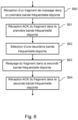
- Fig. 4 illustrates a method for transmitting a message M or a data frame in a hyper robust communication mode called "H-ROBO", according to a second mode of achievement.
- the message M must be transmitted according to the H-ROBO mode by a source node device (for example the node device 133) to a destination node device belonging to its network neighborhood (for example the node device 134).
- the two node devices 133 and 134 are configured to operate communications in multi-band mode and have operated protocol exchanges resulting in a choice of communication in hyper robust H-ROBO communication mode.
- the method starts in a step S400.
- the source node device 133 transmits to the destination node device 134 the message M on a first disjoint frequency band among the plurality of disjoint frequency bands comprising at least two frequency bands, the message M being modulated according to the mode of robust communication.
- the source node device 133 transmits to the destination node device 134 the same message M on a second disjoint frequency band among the plurality of disjoint frequency bands, the message M being, here again, modulated according to the robust mode. It should be noted that the second disjoint frequency band is different from the first disjoint frequency band.
- the first and second disjoint frequency bands are for example selected from a plurality of disjoint frequency bands defined in the G3-PLC standard, i.e. CENELEC A, CENELEC B, and ARIB or FCC.
- the first and second disjoint frequency bands are selected from a subset of the frequency bands defined in the G3-PLC standard, the subset comprising at least two disjoint frequency bands from among all the bands defined in the G3-PLC standard. PLC.
- the method ends in a step S430.
- the hyper-robust mode H-ROBO therefore uses different disjoint frequency bands by transmitting the same message M, or a data frame, simultaneously on these different frequency bands. In each frequency band, the robust mode is used.
- the hyper-robust mode is used when communication between neighboring nodes is difficult, e.g. when a value of an LQI quality indicator for the link in question is lower than a predetermined threshold value.
- the source node device 133 and the destination node device 134 are each based on LQI values received in tone map response information as defined in the G3-PLC standard to choose a transmission mode from among the multi-communication modes. strip (in ROBO mode in each strip) or in hyper-robust mode, and can therefore opt for different modes of communication.
- one of the node devices must adapt its transmission mode so that it is then compatible with the configuration mode chosen by the other node. Thus, it must be able to switch from multi-band transmission mode by fragmentation with ROBO-type modulation in each band to hyper-robust mode, if it detects that the other node device is communicating in hyper-robust H-ROBO mode. .
- FIG. 5 schematically illustrates a method for transmitting a message according to a third embodiment.
- a message M must be transmitted by a source node device (for example the node device 133) to a destination node device belonging to its network neighborhood (for example the node device 134).
- This embodiment is described in particular in connection with the G3-PLC communication standard. However, it is not limited to this single standard and could be applied to other standards, eg to the PRIME specifications (for “Powerline Intelligent Metering Evolution” in English), that is to say in particular in a communication network by carrier currents in line which does not present a mesh structure but which presents a tree structure.
- the method starts at a step S500.
- the message M which is for example encapsulated in an IP packet, eg an IPv6 packet (packet of size up to 1500 bytes), is fragmented into at least two fragments in order to adapt it to the constraints of the MAC layer, and in particular to the size of the MAC frames.
- an IP packet eg an IPv6 packet (packet of size up to 1500 bytes)
- IPv6 packet packet of size up to 1500 bytes
- the G3-PLC standard incorporates the 6LoWPAN protocol, which makes it possible to adapt IPv6 data packets to the constraints of the G3-PLC communication standard, in particular by fragmenting them.
- the MAC frames used by the G3-PLC standard are much smaller in size than the IPv6 packets of 1500 bytes (i.e. 400 bytes available at most per packet for the IP part).
- the adaptation layer of 6LoWPAN sits between the network layer and the MAC sublayer of the OSI model. It receives IPv6 packets of 1280 bytes from the network layer and fragments them if necessary. Of course, in the case of an IPv6 packet small enough to be contained in a single MAC G3-PLC frame, no fragmentation is performed. The method therefore applies in the case where the message M has such a length that it needs to be fragmented.
- Each fragment is generally preceded by a fragmentation header, for example a header comprising 4 or 5 bytes.
- This header contains for example the following information Five bits to identify that it is a fragment.
- the first fragment will have the value "11000” and the following "11100"; eleven bits to indicate the size of the IP packet before fragmentation (“datagram_size” field); sixteen bits to indicate an identifier (“datagram_tag” field) common to all the fragments of the same IP packet; and eight bits to indicate the position (“datagram_offset” field) of the fragment in the IP packet (only present in the fragments following the first).
- datagram_size eleven bits to indicate the size of the IP packet before fragmentation
- datagram_tag sixteen bits to indicate an identifier
- a first disjoint frequency band is associated with a first fragment among said at least two fragments resulting from the fragmentation of the message M, and a second disjoint frequency band, different from the first frequency band, is associated with the other of said at least two fragments.
- the associated first and second frequency bands are for example selected from the plurality of frequency bands defined in the G3-PLC communication standard, ie CENELEC A, CENELEC B, and ARIB or FCC.
- the first and second associated disjoint frequency bands are selected from a subset of the frequency bands defined in the G3-PLC communication standard, the subset comprising at least two bands from among all the bands authorized by G3-PLC .
- fragments originating from the same IP packet can be associated with a view to their transmission at different frequency bands.
- the embodiment described for two fragments can be extended to cases for which more than two fragments are defined, e.g. N fragments where N is a natural number.
- the same disjoint frequency band can be associated with different fragments.
- different disjoint frequency bands are then associated with at least two fragments of the message M among the N fragments.
- the disjoint frequency bands are associated alternately with the fragments.
- the first frequency band is associated with odd fragments (i.e. fragments 1, 3, 5, etc.) and the second frequency band is associated with even fragments (i.e. 2, 4, 6, etc).
- odd fragments i.e. fragments 1, 3, 5, etc.
- even fragments i.e. 2, 4, 6, etc.
- the fragment is transmitted on the frequency band associated with it.
- the transmission of a fragment on the medium ie on the power line, conventionally comprises various steps, in particular a segmentation of the fragments in order to adapt them to the physical layer and an OFDM modulation of the signal. Segmentation consists of partitioning a MAC (acronym for “Media Access Control”) frame into PSDUs (acronym for “PHY Service Data Unit”). All PSDUs from a single fragment are modulated using a single modulation scheme.
- MAC media Access Control
- PSDUs acronym for “PHY Service Data Unit”. All PSDUs from a single fragment are modulated using a single modulation scheme.
- FIG. 6 schematically illustrates a method of relaying a message M received by the first node device 133 from a third node device to the second node device 134, according to a fourth embodiment.
- this fourth embodiment at least two disjoint frequency bands are used in the same determined geographical area.
- the algorithm described by the flowchart of the Fig.6 is capable of being executed by each of the node devices of the communication network 120.
- the present algorithm is thus described below according to an example in which it is executed by the first node device 133, the second node device being the node device 134 and the third node device being the node device 137.
- the node device 133 receives from the node device 137 a fragment in a first disjoint frequency band.
- the transmission of a fragment on the medium, ie on the power line conventionally comprises various steps in particular a segmentation of the fragments in order to adapt them to the physical layer and an OFDM modulation of the signal. Segmentation consists of partitioning a MAC (acronym for “Media Access Control”) frame into PSDUs (acronym for “PHY Service Data Unit”). All PSDUs from a single fragment are modulated using a single modulation scheme.
- the node device 133 After demodulation and decoding of the received fragment according to the demodulation and decoding scheme of the first frequency band, disjoint, transmits an acknowledgment message to the node device 137.
- the node device 133 selects, from among the set of disjoint frequency bands, a second frequency band, different from the first frequency band and which is a frequency band on which the second node device 134 is capable of transmitting and receiving messages .
- the first node device 133 relays the fragment received from the third node device 137 to the second node device 134, after having operated a modulation and a coding of the decoded and demodulated fragment, according to the coding and modulation scheme of the disjoint frequency band selected.
- the first node device 133 receives an acknowledgment message from the second node device 134, recipient of the relayed message.
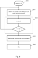
- Fig. 7 schematically illustrates a method for selecting at least one frequency band of the communication network for sending a message according to a fifth embodiment.
- the method described here can be executed each time a message M is sent by each node device which is capable of transmitting and receiving messages on several disjoint frequency bands of the communication network 120.
- the associated disjoint frequency bands are for example selected from the plurality of disjoint frequency bands defined in the G3-PLC communication standard, i.e. CENELEC A, CENELEC B, and ARIB or FCC.
- a node device for example the node device 133, has a message to send on the communication network 120.
- the node device 133 obtains a theoretical bit rate for each of the frequency bands disjoint on which the node device 133 is able to transmit and receive messages.
- each disjoint frequency band has, for each type of modulation used in this disjoint frequency band, a determined theoretical bit rate.
- the node device 133 obtains the theoretical throughput of each frequency band on which the node device 133 is capable of transmitting and receiving messages corresponding to the modulation used for sending the message to the node to which the message must be transferred.
- the node device 133 estimates, for each of the disjoint frequency bands, the theoretical transmission duration of the message in this disjoint frequency band, then during a step S74, the node device 133 interrogates a base of data to obtain results of integration of the occupancy rate of the disjoint frequency band corresponding to the theoretical transmission duration of the message in each frequency band.
- the node device 133 obtains, for each disjoint frequency band, a number of integration results during a first time scale corresponding to the theoretical transmission duration of the message in the disjoint frequency band concerned.
- the node device 133 also obtains a number of integration results during a second time scale corresponding to the time at which the message is to be sent.
- the node device 133 finally obtains a number of results integration during a third time scale corresponding to the day on which the message must be sent.
- the node device 133 selects the disjoint frequency band from among the disjoint frequency bands for which the occupancy rate integration results are the lowest. For example, the node device 133 calculates, for each disjoint frequency band, the mean of the integration results during the first, second and third time scales and selects the disjoint frequency band for which the calculated mean is the lowest.
- a weighting coefficient is assigned to the integration results during the first, second and third time scales before the calculation of the average. For example, a weighting of 10 is assigned to the integration results during the first timescale, a weighting of 12 is assigned to the integration results during the second timescale, and a weighting of 7 is assigned to the integration results during the third timescale.
- Fig. 8 schematically illustrates a method for selecting a communication route between a first node device and a second node device of the communication network 120, of the electrical power supply mesh network type using line carrier communications, according to a sixth mode of achievement.
- the second node device e.g. the node 132
- the second node device is reachable from the first node device, e.g. 133, by at least a first communication route, e.g. the route passing through the nodes 130, 131 and a second communication route, e.g. passing through nodes 134, 135 and 136, different from said first communication route.
- the second node device is reachable from the first node device by a plurality of N communication routes, N being a positive integer.
- N being a positive integer.
- each possible route is identified by an index k with k integer varying from 0 to N-1.
- the method starts at a step S800 where k is equal to zero.
- the second node device obtains a route cost RCk for a communication route of index k among the plurality of N communication routes.
- the route cost RC k is equal to the sum of the link costs LC i,j between two successive node devices i and j, ie located in the same network neighborhood.
- the cost of the route RCi L 133.130 +L 130.131 +L 131.132 .
- the cost RC 2 of the second communication route are equal to L 133.134 +L 134.135 +L 135.136 + L 136.132 .
- the cost of an LC link i,j between two successive node devices is a function of the maximum value among a cost of the LC link i ⁇ j in the forward direction, ie from the transmitter node device to the receiver node device, and a cost of the link LC j ⁇ i in the backward direction, ie from the receiver node device to the transmitter node device.
- adpKrt has a value of 0 and adpKh has a value of 4.
- the second node device will be able to compare the potential routes, and define a preference for the one with the fewest hops.
- a specific metric is defined to determine the costs of the directional links in order to adapt to node devices which have transmission capacities of the multi-band type.
- a node device has multi-band capabilities in the case where it is configured to be able to simultaneously use several disjoint frequency bands, eg CENELEC-A and FCC, instead of choosing and operating in a single disjoint frequency band.
- the node device in question may fragment the message into different fragments according to the 6LoWPAN protocol. The fragmentation process is more particularly described in section 5.3 of the RFC 4944 recommendation (published in September 2007). Each fragment is then sent independently of the other fragments on frequency bands which may be different.
- the associated frequency bands are for example selected from the set of frequency bands authorized by G3-PLC, ie CENELEC A, CENELEC B, ARIB and FCC.
- the associated first and second frequency bands are selected from a subset of the frequency bands authorized by G3-PLC, the subset comprising at least two bands from among all the bands authorized by G3-PLC.
- a node device having multi-band capabilities can transmit the same message simultaneously in all frequency bands of the set of frequency bands supported (by transmitter and receiver). This mode of transmission is called in the following the hyper-robust mode.
- the robust mode of G3-PLC is then used. In this way, in the event of a large frequency disturbance on a frequency band, the message can nevertheless succeed in passing over to another frequency band. Indeed, the receiver only needs to succeed in picking up the message on only one of the frequency bands on which it was transmitted.
- the hyper-robust mode is a particular mode newly defined for the case of node devices having multi-band capacities.
- a node device having multi-band capabilities can transmit a message over all of the frequency bands, which then constitute a so-called extended frequency band.
- the multi-band capacity of a node device is characterized by the fact that the node is capable of exploiting several frequency bands simultaneously instead of a single and unique band as is conventionally the case. in the case of the G3-PLC standard.
- a device having multi-band capabilities can benefit from the characteristics of the different frequency bands in terms of bit rate, range, resistance to disturbances.
- the route cost as defined by G3-PLC in its appendix D does not make it possible to take account of these multi-band capacities of the node device. Indeed, the G3-PLC communication standard only allows the use of a single frequency band for a given network. According to a particular embodiment, the cost of the link LC i ⁇ j in a given direction, ie in the forward or reverse direction, depends on the cost of the link, in said given direction, calculated for each frequency band LC i ⁇ j [m] of the set of frequency bands used by said two successive node devices i and j to communicate, said set comprising at least two different frequency bands.
- the index k is incremented by 1 and compared to N-1 during a step S820, k is incremented by 1 and compared to N-1. If k is less than or equal to N-1 then the method continues at step S810, otherwise it continues at step S830.
- the second node device selects, among said N communication routes, the communication route corresponding to the lowest route cost.
- the process of Fig. 8 ends at step S840.
- a cost LC i ⁇ j of a directional link between a first node device and a second node device is calculated from a cost LC i ⁇ j [m] of a directional link per disjoint frequency band, m being an index identifying the frequency band, and m is an integer varying from 0 to NBP-1, where NBP is an integer equal to the number of usable disjoint frequency bands. For example, NBP can be equal to 4.
- an index m equal to 0 corresponds to the CENELEC-A band
- an index m equal to 1 corresponds to the FCC band
- an index m equal to 2 corresponds to the band CENELEC-B
- an m index equal to 3 corresponds to the ARIB band.
- This process starts at step S8100 when m is zero.
- m is incremented by 1 and compared to the number NBP-1. If m is less than or equal to NBP-1 then the process continues at step S8110, otherwise it continues in sequence at step S8130.
- step S8140 subsequent to step 8130, the overall directional cost LC i ⁇ j is calculated.
- the hyper-robust mode is not used in equations (1) and (2) and adpKhr has a zero value.
- the calculation process then ends at a final step S8150.
- Steps S8100 to S8150 are repeated to calculate the global directional cost Lc j ⁇ i and thus to deduce therefrom the cost LC i,j .
- Steps S8100 to S8150 are not represented on the Fig. 8 but can be used as references for a good understanding of the method for calculating the cost LC i,j of a link described above, in particular because of the possible looping between steps S8120 and S8110.
- FIG. 9 illustrates a method for determining a mode of communication between two node devices neighboring each other in the communication network 120, according to a seventh embodiment.
- These node devices are, by way of example, the node device 133 operating as an initiator node device and the neighbor node device 134, operating as a target node device.
- the node devices 133 and 134 are configured to communicate with each other according to at least one mode of communication in at least one disjoint frequency band. It is considered that the node devices 133 and 134 are then normally operational at this point and that an exchange of messages can be initiated.
- the initiator node device 133 sends, in step S91, a message comprising information according to which a request for channel estimation in an extended frequency band EB is requested to the target node device, and waits for a predetermined time for a possible message in response. At the end of the predetermined period, the initiator node device 133 checks in step S912, whether a response has indeed been received in the form of a message comprising information representative of a channel estimate in the frequency band EB.
- the initiator node device 133 records in step S95 the information received and representative of a channel estimate in the extended frequency band EB, in its neighborhood table NT-REC, and determines a preferred mode of communication, taking into account in particular the various information available in the neighborhood table NT-REC. For example, the initiator node device 133 determines that the extended frequency band communication mode EB is the most advantageous communication mode at this moment to communicate with the target node device 134, and initiates a transmission in this mode there, in the extended frequency band EB, in step S96.
- the initiator node device 133 in the absence of a response from the target node device 134 after a predetermined time, the initiator node device 133 considers that the target node device 134 does not support communication according to an in-band communication mode. extended and sends, during steps S92 and S93, messages respectively comprising a request for channel estimation in the frequency band B1 and a request for channel estimation in the frequency band B2. The initiator node device 133 then waits for a possible response to at least one of these two messages, or to each of these two messages, and records the information representative of one or more channel estimates, received in response, in one or more several neighborhood tables NT-REC, before communicating later in step S6.
- the method resumes at step S92 and the initiator node device again sends messages to the target node device, until a response is obtained in at least one of the two frequency bands B1 and B2.
- a new message comprising a channel estimation request (TMR indicator set to 1, for example, in G3-PLC) can be sent as soon as data must be transmitted to the target node device 134.
- step S6 When communications are established in step S6, in a determined communication mode between the two node devices, and in the absence of a communication problem detected during a step S962 aimed at defining a communication quality level, the communications continue according to the selected communication mode. Conversely, if a communication quality problem is detected, the determination process is restarted from step S91.
- the determination of the transmission mode comprises a step of comparing first transmission quality indicators respectively determined, for each of the frequency bands, from the recorded information associated with each of the at least two frequency bands B1 and B2.
- the determination of the transmission mode may further comprise a selection of a so-called "robust” transmission mode. » using BPSK modulation and systematic repetition of the transmitted bits (for example, each bit is repeated four times or six times during a transmission).
- the selection of a so-called "robust” transmission mode depends, for example, on a level of transmission quality defined from an estimate of a transmission channel established via a multi-band transmission in said at least two frequency bands B1 and B2.
- Fig. 10 schematically illustrates an example of the internal architecture of any node device of the communication network 120.
- the Fig. 10 illustrates an internal arrangement of the node device 133.
- Such a node device is qualified as multi-band because it is capable of transmitting a message on several disjoint frequency bands used in parallel.
- the Fig. 10 could also schematically illustrate an example of hardware architecture of a processing module included in the node device 133.
- the node device 133 then comprises, connected by a communication bus 1300: a processor or CPU (Central Processing Unit) 1331; a random access memory RAM (Random Access Memory) 1332; a read-only memory ROM 1333; a storage unit such as a hard disk (or a storage medium reader, such as an SD ("Secure Digital" in English) card reader 1334; at least one communication interface 1335 allowing the node device 133 to communicate with the node devices belonging to its network neighborhood, such as, for example, the node devices 134 and 137.
- a communication bus 1300 a processor or CPU (Central Processing Unit) 1331; a random access memory RAM (Random Access Memory) 1332; a read-only memory ROM 1333; a storage unit such as a hard disk (or a storage medium reader, such as an SD ("Secure Digital" in English) card reader 1334; at least one communication interface 1335 allowing the node device 133 to communicate with the node devices belonging to its network neighborhood, such as
- Processor 1301 is capable of executing instructions loaded into RAM 1332 from ROM 1333, external memory (not shown), storage media (such as an SD card), or a communications network. When the node device is powered up, processor 1331 is able to read instructions from RAM 1332 and execute them. These instructions form a computer program causing the implementation, by the processor 1331, of all or part of the exchanges and methods described in relation to the aforementioned figures illustrating a method according to an embodiment previously described.
- node device 133 includes electronic circuitry configured to implement the methods described in connection with node device 133 (likewise for node device 134).
- Fig. 11 schematically illustrates an example of multi-band reception architecture. More particularly, a reception processing chain 1120 of a node device is illustrated, such as the node device 134.
- the reception processing chain 1120 comprises two demodulators DEM 1 1124 and DEM2 1126 and can therefore process a band, multi-band or extended frequency band (here with the conjunction of two disjoint frequency bands).
- the processing chain 1120 comprises a programmable gain stage AMP 1121 configured to support all the input dynamics of the multiple frequency bands and to avoid possible saturation of the signals of one of the disjoint frequency bands.
- An analog-digital conversion stage ECH 1122 performs the conversion and controls the gain of the programmable gain stage AMP 21.
- the ECH conversion stage 22 is shared and the sampling frequency is defined with respect to the frequency of sampling required in the disjoint frequency band having the highest frequency.
- the separation of the data transmitted in the different frequency bands is then carried out with digital filters F1 1123 and F2 1125 respectively.
- the frequency bands being disjoint, their respective signals can be easily distinguished in this way.
- the data at the output of each of the digital filters F1 and F2 are then respectively transmitted to the demodulators DEM1 1124 and DEM2 1126.
- the output of the demodulators DEM1 1124 and DEM2 1126 is processed by an FEC decoder 1128, via a first memory MEM1 1127, called deinterleaving memory.
- the data is loaded according to a predefined arrangement so as to be able to deinterleave them according to several deinterleaving modes which correspond to the inverse of the interleaving operations carried out on transmission.
- An FEC decoder deinterleave circuit 1128 reads the data from the first deinterleave memory MEM1 1127 and is configured to check whether the deinterleaved data appears coherent.
- the deinterleaved data appear coherent, they are recorded in a second memory MEM2 1129, called the reception memory of the MAC link sub-layer.
- the data thus stored in the reception memory MEM2 1129 constitute data frames ready to be processed by the MAC layer of the ISO model.
- the consistency of the data deinterleaved according to a deinterleaving mode specific to an extended frequency band transmission is first checked. If the data is not coherent, this means that another mode of transmission has been used for the transmission of the data and a second deinterleaving operation, by means of each of the single-band deinterleaving tables is carried out.
- the architecture presented is not limiting, and a node device can comprise, for example, three or more demodulators (and their corresponding filters), depending on the number of frequency bands in which it must be able to perform data reception.
- the methods described above according to the various embodiments are particularly advantageous in the context of a mesh network of the G3-PLC type to increase the communication performance between node devices of such a network.
- a node device being configured to transmit in an extended frequency band can also use a multi-band communication mode implementing a fragmentation of a message, each fragment being capable of being transmitted on a frequency band disjoint among those usable.
- a node device configured to implement a method of optimizing the transmission time can also be configured to optimize the bandwidth on the communication network in which it operates.
Description
Au moins un mode de réalisation de la présente invention concerne un procédé de transmission d'un message à partir d'un premier dispositif noeud vers un second dispositif noeud appartenant à un voisinage réseau du premier dispositif noeud, lesdits premier et second dispositifs noeuds appartenant à un réseau utilisant des communications par courants porteurs en ligne. Au moins un mode de réalisation de la présente invention concerne un dispositif mettant en oeuvre le procédé.At least one embodiment of the present invention relates to a method for transmitting a message from a first node device to a second node device belonging to a network neighborhood of the first node device, said first and second node devices belonging to a network using power line communications. At least one embodiment of the present invention relates to a device implementing the method.
Les communications par courants porteurs en ligne PLC (sigle signifiant « Power Line Communications », en anglais) se développent, notamment dans le cadre des réseaux d'alimentation électrique de type AMM (sigle signifiant « Automated Meter Management », en anglais). Des réseaux de communication sont ainsi implémentés dans des réseaux d'alimentation électrique pour la collecte automatisée par un dispositif noeud de base (aussi appelé « concentrateur de données ») du réseau, auprès de compteurs électriques intelligents (« smart electricity meters » en anglais), de données de relevés de consommation énergétique que lesdits compteurs électriques intelligents sont respectivement en charge de surveiller. La norme de communication G3-PLC est définie pour permettre aux différents dispositifs noeuds (notamment concentrateur de données et compteurs électriques intelligents) d'un tel réseau de communiquer entre eux. La norme est spécifiée dans la recommandation ITU-T G.9903 laquelle décrit notamment la couche physique (PHY) et la couche liaison de données (DLL, sigle de « Data Link Layer », en anglais) du modèle OSI (acronyme de « Open Systems Interconnection », en anglais). La norme G3-PLC est destinée à être exploitée dans des bandes fréquentielles allant de 10 à 490 kHz. Elle supporte plus particulièrement les bandes fréquentielles suivantes : la bande fréquentielle CENELEC A, qui va approximativement de 35 kHz à 91 kHz ; la bande fréquentielle FCC, qui va approximativement de 150 kHz à 480 kHz ; la bande fréquentielle ARIB, qui va approximativement de 150 kHz à 400 kHz ; et la bande fréquentielle CENELEC B, qui va approximativement de 98 kHz à 122 kHz. Ces différentes bandes fréquentielles présentent des caractéristiques différentes en termes de débit, de portée, et de résistance aux perturbateurs, notamment. Un exemple d'art antérieur peut être trouvé dans
Toutefois, la norme G3-PLC ne permet l'utilisation que d'une seule desdites bandes fréquentielles pour un dispositif noeud donné. Plus exactement, les dispositifs noeuds récents peuvent parfois supporter plusieurs bandes fréquentielles, mais pas en même temps. Une reconfiguration est alors nécessaire pour passer d'une première bande fréquentielle à une seconde bande fréquentielle. Ainsi, lorsque dans un réseau de communication il est nécessaire de reconfigurer, dans une nouvelle bande fréquentielle, un ensemble de dispositifs concentrateurs de données et un ensemble de compteurs électriques qui lui sont associés, une reconfiguration peut se montrer particulièrement complexe. Par exemple, un dispositif compteur n'ayant pas pu réceptionner un message lui indiquant de changer de bande fréquentielle peut devenir incapable de communiquer avec le dispositif concentrateur de données auquel il est associé, après que ce dernier ait pu, quant à lui, changer de bande fréquentielle.However, the G3-PLC standard allows the use of only one of said frequency bands for a given node device. More precisely, recent node devices can sometimes support several frequency bands, but not at the same time. A reconfiguration is then necessary to pass from a first frequency band to a second frequency band. Thus, when in a communication network it is necessary to reconfigure, in a new frequency band, a set of data concentrator devices and a set of electricity meters which are associated therewith, a reconfiguration can prove to be particularly complex. For example, a counter device that has not been able to receive a message telling it to change frequency band may become unable to communicate with the data concentrator device with which it is associated, after the latter has been able to change frequency band.
Or, les besoins en termes de ressources des réseaux de communication, notamment dans le déploiement des réseaux d'alimentation électrique de type AMM, grandissent de jour en jour. La bande fréquentielle, pour laquelle les éléments constitutifs d'un réseau ont été certifiés, peut se retrouver en limite de capacité, ce qui fait obstacle à une augmentation du nombre d'échanges dans le réseau, par exemple pour introduire de nouvelles fonctionnalités ou encore de nouveaux besoins applicatifs, par exemple.However, the needs in terms of resources of the communication networks, in particular in the deployment of the power supply networks of the AMM type, are growing day by day. The frequency band, for which the components of a network have been certified, may end up at the capacity limit, which hinders an increase in the number of exchanges in the network, for example to introduce new functionalities or even new application needs, for example.
Il est souhaitable de pallier ces différents inconvénients de l'état de la technique. Il est ainsi notamment souhaitable de proposer une solution de communication par courant porteur en ligne permettant d'augmenter la capacité de nombre d'échanges dans le réseau de communication. Il est notamment souhaitable de proposer une solution applicable aux réseaux d'alimentation électrique de type AMM.It is desirable to overcome these various disadvantages of the state of the art. It is thus particularly desirable to propose an on-line carrier current communication solution making it possible to increase the capacity of the number of exchanges in the communication network. It is particularly desirable to propose a solution applicable to power supply networks of the AMM type.
La présente invention est définie par les revendications indépendantes. D'autres modes de réalisation préférés peuvent être trouvés dans les revendications dépendantes. La présente application divulgue un procédé de transmission de données, sous forme de messages, dans un réseau de communication par courants porteurs en ligne, le procédé étant exécuté dans un premier dispositif noeud dudit réseau configuré pour communiquer dans une pluralité de bandes fréquentielles disjointes avec un second dispositif noeud dudit réseau, le procédé comprenant une émission d'un message dans un mode de transmission utilisant parallèlement au moins deux bandes fréquentielles disjointes parmi ladite pluralité de bandes fréquentielles disjointes, et le procédé étant caractérisé en ce que l'émission d'un message dans un mode de transmission utilisant parallèlement au moins deux bandes fréquentielles disjointes comprend une utilisation d'une bande fréquentielle dite bande fréquentielle étendue mcomprenant au oins deux bandes fréquentielles disjointes parmi ladite pluralité de bandes fréquentielles disjointes, chaque bande fréquentielle disjointe comprenant une pluralité de sous-porteuses, le procédé comprenant en outre une étape d'entrelacer des données d'un message à transmettre adaptée à une émission desdites données réparties sur l'ensemble desdites sous-porteuses.La présente application divulgue un dispositif noeud destiné à être utilisé dans un réseau de communication par courants porteurs en ligne, le dispositif noeud étant configuré pour communiquer dans une pluralité de bandes fréquentielles disjointes avec un second dispositif noeud dudit réseau et pour appliquer un mode de transmission dans, parallèlement, au moins deux bandes fréquentielles disjointes parmi une pluralité de bandes fréquentielles disjointes, le dispositif noeud étant caractérisé en ce qu'il est configuré pour émettre ledit message dans un mode de transmission utilisant parallèlement au moins deux bandes fréquentielles disjointes en utilisant une bande fréquentielle dite « bande fréquentielle étendue » comprenant au moins deux bandes fréquentielles disjointes parmi ladite pluralité de bandes fréquentielles disjointes, chaque bande fréquentielle disjointe comprenant une pluralité de sous-porteuses, le dispositif noeud comprenant une circuiterie d'entrelacement pour entrelacer des données d'un message à transmettre adaptée à une émission desdites données réparties sur l'ensemble desdites sous-porteuses.The present invention is defined by the independent claims. Other preferred embodiments can be found in the dependent claims. The present application discloses a method for transmitting data, in the form of messages, in a power line communication network, the method being executed in a first node device of said network configured to communicate in a plurality of disjoint frequency bands with a second node device of said network, the method comprising transmission of a message in a transmission mode using in parallel at least two disjoint frequency bands among said plurality of disjoint frequency bands, and the method being characterized in that the transmission of a message in a mode of transmission using in parallel at least two disjoint frequency bands comprises using a so-called extended frequency band m comprising at least two disjoint frequency bands among said plurality of disjoint frequency bands, each disjoint frequency band comprising a plurality of sub-carriers, the method further comprising a step to interleave data of a message to be transmitted adapted to a transmission of said data distributed over all of said sub-carriers. node device being configured to communicate in a plurality of disjoint frequency bands with a second node device of said network and to apply a transmission mode in, in parallel, at least two disjoint frequency bands among a plurality of disjoint frequency bands, the node device being characterized in that it is configured to transmit said message in a mode of transmission using at least two disjoint frequency bands in parallel by using a so-called “extended frequency band” frequency band comprising at least two disjoint frequency bands among said plurality of disjoint frequency bands, each disjoint frequency band comprising a plurality of sub-carriers, the node device comprising interleaving circuitry for interleaving data of a message to be transmitted adapted to transmission of said data distributed over all of said sub-carriers.
L'invention a également pour objet un réseau de communication par courants porteurs en ligne comprenant une pluralité de dispositifs noeuds tels que précédemment décrits.The invention also relates to an in-line carrier current communication network comprising a plurality of node devices as previously described.
L'invention concerne également un produit programme d'ordinateur comprenant des instructions de codes de programme pour exécuter des étapes du procédé précédemment décrit lorsque le programme est exécuté par un processeur, ainsi qu'un support de stockage d'informations comprenant un tel produit programme d'ordinateur.The invention also relates to a computer program product comprising program code instructions for executing steps of the method described above when the program is executed by a processor, as well as an information storage medium comprising such a program product of computer.
Les caractéristiques de l'invention mentionnées ci-dessus, ainsi que d'autres, apparaîtront plus clairement à la lecture de la description suivante d'au moins un exemple de réalisation, ladite description étant faite en relation avec les dessins joints, parmi lesquels :
- [
Fig. 1 ] illustre un réseau d'alimentation électrique utilisant des communications par courants porteurs en ligne comprenant un dispositif mettant en oeuvre le procédé selon l'invention ; - [
Fig. 2 ] est un ordinogramme illustrant un premier mode de réalisation utilisant une transmission en bande fréquentielle étendue ; - [
Fig. 3 ] est une représentation schématique d'un entrelacement de données adapté à une communication en bande fréquentielle étendue, selon le premier mode de réalisation ; - [
Fig. 4 ] est un ordinogramme illustrant un deuxième mode de réalisation utilisant une transmission dans un mode de communication robuste en multi-bandes ; - [
Fig. 5 ] est un ordinogramme illustrant un troisième mode de réalisation utilisant une transmission d'un message fragmenté sur plusieurs bandes fréquentielles disjointes ; - [
Fig. 6 ] est un ordinogramme illustrant un quatrième mode de réalisation visant à optimiser le temps de transmission d'un message en multi-bandes ; - [
Fig. 7 ] est un ordinogramme illustrant un cinquième mode de réalisation visant à optimiser la bande passante pour une transmission en multi-bandes ; - [
Fig. 8 ] est un ordinogramme illustrant un sixième mode de réalisation comprenant un calcul de coûts de routes pour une communication en multi-bandes ; - [
Fig. 9 ] est un ordinogramme illustrant un septième mode de réalisation comprenant une détermination par un dispositif noeud des capacités de communication d'un dispositif noeud voisin en vue d'une communication en multi-bandes ; - [
Fig. 10 ] illustre schématiquement l'architecture interne d'un dispositif noeud du réseau de communication déjà illustré sur laFig. 1 ; - [
Fig. 11 ] illustre schématiquement un exemple d'architecture d'une chaîne de réception d'un dispositif noeud configuré pour opérer un mode de réception en multi-bandes.
- [
Fig. 1 ] illustrates an electrical power supply network using line carrier communications comprising a device implementing the method according to the invention; - [
Fig. 2 ] is a flowchart illustrating a first embodiment using extended frequency band transmission; - [
Fig. 3 ] is a schematic representation of a data interleaving suitable for extended frequency band communication, according to the first embodiment; - [
Fig. 4 ] is a flowchart illustrating a second embodiment using transmission in a robust multi-band communication mode; - [
Fig. 5 ] is a flowchart illustrating a third embodiment using transmission of a fragmented message over several disjoint frequency bands; - [
Fig. 6 ] is a flow chart illustrating a fourth embodiment aimed at optimizing the transmission time of a multi-band message; - [
Fig. 7 ] is a flowchart illustrating a fifth embodiment aimed at optimizing the bandwidth for a multi-band transmission; - [
Fig. 8 ] is a flowchart illustrating a sixth embodiment comprising a calculation of route costs for multi-band communication; - [
Fig. 9 ] is a flowchart illustrating a seventh embodiment comprising a determination by a node device of the communication capabilities of a neighboring node device with a view to multi-band communication; - [
Fig. 10 ] schematically illustrates the internal architecture of a node device of the communication network already illustrated on theFig. 1 ; - [
Fig. 11 ] schematically illustrates an example of architecture of a reception chain of a node device configured to operate a multi-band reception mode.
La
Le réseau de communication 120 a une structure maillée. La structure maillée du réseau de communication 120 est représentée schématiquement sur la
Le réseau de communication 120 comporte ainsi une pluralité de dispositifs noeuds 130, 131, 132, 133, 134, 135, 136, 137, 138, 139. A chacun des dispositifs noeuds du réseau de communication 120 est associé un voisinage réseau. Par exemple, le dispositif noeud 133 de la
Le réseau de communication 120 s'appuie sur un protocole de routage de type réactif, tel que, par exemple, le protocole LOADng (« Lightweight On-demand Ad hoc Distance-vector Routing Protocol - Next Génération » en anglais). Contrairement aux protocoles de routage de type proactif qui s'appuient sur une connaissance globale de topologie réseau, les protocoles de routage de type réactif s'appuient sur des découvertes de routes à la demande, chaque dispositif noeud du réseau ayant alors besoin uniquement d'avoir connaissance de son propre voisinage réseau pour router des données dans le réseau de communication 120. Pour découvrir une route appropriée dans le réseau de communication 120 depuis un dispositif noeud source (par exemple le dispositif noeud 133) jusqu'à un dispositif noeud destination (par exemple le dispositif noeud 132), il est connu que le dispositif noeud source diffuse (« broadcast » en anglais) une requête de découverte de route, appelée RREQ (« Route REQuest » en anglais). Cette requête de découverte de route est reçue par chaque dispositif noeud dans le voisinage réseau dudit dispositif noeud source. Chaque dispositif noeud dans le voisinage réseau dudit dispositif noeud source relaie, par diffusion, ladite copie de la requête si ledit dispositif noeud en question n'est pas le dispositif noeud destination. Par diffusion de proche en proche, plusieurs copies de la requête de découverte de route sont typiquement reçues par le dispositif noeud destination, chacune de ces copies ayant suivi un chemin différent dans le réseau de communication 120.The
L'utilisation de tables de routage mémorisées dans les dispositifs noeuds permet d'effectuer des communications point-à-point (« unicast » en anglais) entre toute paire de dispositifs noeuds du réseau de communication 120. Des dispositifs noeuds intermédiaires servent donc de relais lorsque les dispositifs noeuds de ladite paire ne sont pas dans le voisinage réseau l'un de l'autre, les communications s'opèrent ainsi de proche en proche, chaque dispositif noeud s'appuyant sur un de ses propres voisins pour faire suivre des messages jusqu'à leurs destinataires respectifs.The use of routing tables stored in the node devices makes it possible to carry out point-to-point communications (“unicast” in English) between any pair of node devices of the
Pour communiquer entre dispositifs noeuds voisins (c'est-à-dire des dispositifs noeuds qui sont dans le voisinage réseau l'un de l'autre), les messages sont transmis sous forme de trames modulées. Lorsqu'une trame modulée est spécifiquement adressée à un dispositif noeud voisin et qu'elle est correctement démodulée par celui-ci, ledit dispositif noeud voisin retransmet un acquittement ACK au dispositif noeud qui lui a adressé ladite trame modulée. L'acquittement ACK est transmis sur la même bande fréquentielle que la trame modulée à laquelle ledit acquittement ACK est associé.To communicate between neighboring node devices (that is to say node devices which are in the network neighborhood of one another), the messages are transmitted in the form of modulated frames. When a modulated frame is specifically addressed to a neighbor node device and it is correctly demodulated by the latter, said neighbor node device retransmits an acknowledgment ACK to the node device which sent said modulated frame to it. The acknowledgment ACK is transmitted on the same frequency band as the modulated frame with which said acknowledgment ACK is associated.
Plusieurs bandes fréquentielles sont définies pour supporter la transmission de ces trames modulées, un schéma de modulation adapté étant associé avec chacune de ces bandes fréquentielles. Chaque trame transmise sous forme de signaux modulés débute par un préambule prédéfini en fonction du schéma de modulation selon lequel lesdits signaux ont été modulés. Le préambule est adapté pour permettre de se synchroniser en réception sur ladite trame, c'est-à-dire de pouvoir déterminer un instant effectif de début de trame. Pour ce faire, le préambule comporte typiquement une pluralité de copies successives d'un même symbole. Le contenu effectif et la durée du préambule sont ainsi prédéfinis et dépendent du schéma de modulation utilisé. Les préambules de plusieurs trames sont identiques lorsque le même schéma de modulation est appliqué, et diffèrent sinon.Several frequency bands are defined to support the transmission of these modulated frames, a suitable modulation scheme being associated with each of these frequency bands. Each frame transmitted in the form of modulated signals begins with a predefined preamble according to the modulation scheme according to which said signals have been modulated. The preamble is adapted to make it possible to synchronize reception on said frame, that is to say to be able to determine an effective frame start instant. To do this, the preamble typically comprises a plurality of successive copies of the same symbol. The actual content and the duration of the preamble are thus predefined and depend on the modulation scheme used. The preambles of multiple frames are identical when the same modulation scheme is applied, and differ otherwise.
Les schémas de modulation applicables (et des schémas de démodulation correspondants) sont préférentiellement des schémas de modulation (respectivement schémas de démodulation) multi-porteuse de type OFDM (« Orthogonal Frequency Division Multiplex » en anglais).The applicable modulation schemes (and corresponding demodulation schemes) are preferably multi-carrier modulation schemes (respectively demodulation schemes) of the OFDM (Orthogonal Frequency Division Multiplex) type.
En termes de bandes fréquentielles utilisables dans le cadre de la mise en oeuvre du réseau de communication 120, on peut citer : la bande fréquentielle CENELEC A, qui va approximativement de 35 kHz à 91 kHz ; la bande fréquentielle FCC, qui va approximativement de 150 kHz à 480 kHz ; la bande fréquentielle ARIB, qui va approximativement de 150 kHz à 400 kHz ; et la bande fréquentielle CENELEC B, qui va approximativement de 98 kHz à 122 kHz. Il est alors possible d'utiliser : un premier schéma de modulation à trente-six porteuses dans la bande fréquentielle CENELEC A ; un second schéma de modulation à soixante-douze porteuses dans la bande fréquentielle FCC ; un troisième schéma de modulation à cinquante-quatre porteuses dans la bande fréquentielle ARIB ; et un quatrième schéma de modulation à seize porteuses dans la bande fréquentielle CENELEC B. Il apparaît de ce qui précède, qu'un dispositif noeud peut utiliser simultanément plusieurs bandes fréquentielles disjointes pour communiquer avec un ou plusieurs de ses voisins, en appliquant un mécanisme de transmission adapté. Toutefois, il apparaît que les bandes fréquentielles ARIB et FCC ne peuvent pas être utilisées simultanément par un même dispositif noeud, étant donné qu'elles se recouvrent. Avantageusement, au moins certains des dispositifs noeuds 130, 131, 132, 133, 134, 135, 136, 137, 138, 139 sont configurés pour communiquer dans plusieurs bandes fréquentielles disjointes. Il est dès lors important, pour un dispositif noeud donné, de pouvoir déterminer quels sont les modes de communication supportés par un dispositif noeud dans son voisinage réseau. Les termes « modes de communications supportés » désignent un ou plusieurs modes de communication natifs d'un dispositif noeud, c'est-à-dire que ce dernier est capable d'implémenter du fait de ses configurations possibles, et impliquent aussi que ce ou ces modes de communication natifs soient utilisables à un instant donné, compte tenu des éventuelles perturbations qui peuvent exister. Les perturbations peuvent être issues, par exemple, d'un environnement bruité.In terms of frequency bands that can be used in the context of the implementation of the
Un échange de messages selon un protocole prédéfini permet, par exemple, à un premier dispositif noeud d'obtenir des informations quant aux capacités de communication d'un second dispositif noeud voisin. Par exemple, le premier dispositif noeud adresse au second dispositif noeud voisin un exemplaire d'un premier message dans chacune des bandes fréquentielles dans lesquelles il peut communiquer du fait de sa configuration, et le dispositif noeud voisin est configuré pour reconnaître un tel message et y répondre par un second message dans chacune des bandes fréquentielles dans laquelle il a pu le recevoir.An exchange of messages according to a predefined protocol allows, for example, a first node device to obtain information regarding the communication capabilities of a second neighboring node device. For example, the first node device sends to the second neighboring node device a copy of a first message in each of the frequency bands in which it can communicate due to its configuration, and the neighboring node device is configured to recognize such a message and respond with a second message in each of the frequency bands in which it was able to receive it.
Dans un contexte G3-PLC, par exemple, les exemplaires du premier message contiennent une information selon laquelle une estimation de canal est sollicitée auprès du dispositif noeud voisin, pour la bande fréquentielle dans laquelle il a reçu le message (requête dite « Tone Map »). Avantageusement, l'information selon laquelle une estimation canal est sollicitée auprès du second dispositif noeud voisin par le premier dispositif noeud est alors un indicateur Tone Map Request d'un entête de contrôle de trame défini selon la recommandation ITU-T G9903. Ainsi, le second dispositif noeud voisin répondra à la requête Tone Map Request en envoyant au premier dispositif noeud, dans chacune des bandes fréquentielles dans laquelle il a reçu un exemplaire du premier message, un second message comprenant des informations représentatives d'au moins une estimation de canal sous la forme d'un bloc de données Tone Map Response tel que défini selon la recommandation ITU-T G9903.In a G3-PLC context, for example, the copies of the first message contain information according to which a channel estimate is requested from the neighboring node device, for the frequency band in which it received the message (request called “Tone Map” ). Advantageously, the information according to which a channel estimate is requested from the second neighboring node device by the first node device is then a Tone Map Request indicator of a frame control header defined according to ITU-T recommendation G9903. Thus, the second neighboring node device will respond to the Tone Map Request request by sending to the first node device, in each of the frequency bands in which it received a copy of the first message, a second message comprising information representative of at least one estimate channel in the form of a Tone Map Response data block as defined according to the ITU-T G9903 recommendation.
Le premier dispositif pourra donc connaître et mémoriser des informations quant aux bandes fréquentielles qu'il peut utiliser pour communiquer avec le second dispositif noeud voisin. Avantageusement, certains des dispositifs noeuds 130 à 139 sont configurés pour opérer au moins un mode de communication utilisant parallèlement plusieurs bandes fréquentielles disjointes. Ainsi le dispositif noeud 133, par exemple, est configuré pour communiquer dans une seule bande fréquentielle disjointe, parallèlement dans plusieurs bandes fréquentielles disjointes (multi-bandes) ou encore en bande fréquentielle étendue.The first device will therefore be able to know and store information about the frequency bands that it can use to communicate with the second neighboring node device. Advantageously, some of the
Selon un mode de réalisation de l'invention, au moins une partie des dispositifs noeuds 130, 131, 132, 133, 134, 135, 136, 137, 138, 139 supportant des modes de communication dans plusieurs bandes fréquentielles disjointes supporte en outre un mode de communication en bande fréquentielle dite « bande fréquentielle étendue ». Une bande fréquentielle étendue comprend avantageusement plusieurs bandes fréquentielles disjointes. Ainsi une bande fréquentielle étendue peut comprendre deux, trois ou quatre bandes fréquentielles disjointes, par exemple, ou plus encore. Chaque bande fréquentielle disjointe utilise une pluralité de sous porteuses.According to one embodiment of the invention, at least part of the
La détermination de la capacité d'un dispositif noeud voisin à communiquer dans une bande fréquentielle étendue est similaire à ce qui est précédemment décrit pour la détermination des différents modes de communication supportés par un dispositif, dès lors que la bande fréquentielle étendue est communément définie entre les différents dispositifs noeuds voisins du réseau de communication. Ainsi, selon un mode de réalisation, la bande fréquentielle étendue peut être définie comme comprenant la bande fréquentielle CENELEC A, la bande fréquentielle CENELEC B et la bande FCC. Selon une variante, la bande fréquentielle étendue peut être définie comme comprenant la bande fréquentielle CENELEC A, la bande fréquentielle CENELEC B et la bande fréquentielle ARIB. Un premier dispositif noeud peut donc émettre une requête en estimation de canal (requête dite « TONE MAP ») dans la bande fréquentielle étendue pour déterminer si un second dispositif noeud voisin supporte des communications dans la bande fréquentielle étendue.The determination of the ability of a neighboring node device to communicate in an extended frequency band is similar to what is previously described for the determination of the different communication modes supported by a device, since the extended frequency band is commonly defined between the various neighboring node devices of the communication network. Thus, according to one embodiment, the extended frequency band can be defined as comprising the CENELEC A frequency band, the CENELEC B frequency band and the FCC band. Alternatively, the extended frequency band may be defined as comprising the CENELEC A frequency band, the CENELEC B frequency band and the ARIB frequency band. A first node device can therefore send a channel estimation request (request called a “TONE MAP” request) in the extended frequency band to determine whether a second neighboring node device supports communications in the extended frequency band.
La
Au terme d'une étape d'initialisation S20, les premier et second dispositifs noeuds 133 et 134 sont configurés pour communiquer l'un avec l'autre selon au moins un mode de communication dans au moins une bande fréquentielle. Il est considéré que les dispositifs sont alors normalement opérationnels, à ce stade, et qu'un échange de messages peut être initié.At the end of an initialization step S20, the first and
Selon un mode de réalisation, le premier dispositif noeud 133 est configuré lors d'une étape S21 pour opérer des communications dans une bande fréquentielle étendue. Cette configuration est par exemple réalisée par une écriture, par un module de contrôle du premier dispositif noeud 133, d'un indicateur de validation de bande fréquentielle étendue. Selon un mode de réalisation, cet indicateur est un élément binaire (bit) positionné à « 1 » dans un registre de configuration du dispositif noeud 133 qui contrôle un entrelacement de données à émettre selon un mode d'entrelacement propre à une transmission en bande fréquentielle étendue.According to one embodiment, the
La configuration du premier dispositif noeud 133 dans un mode de communication en bande fréquentielle étendue peut être réalisée, par exemple, après que le premier dispositif noeud 133 ait adressé une requête en estimation de canal, laquelle requête comprend un indicateur selon lequel une bande fréquentielle étendue est concernée par cette requête, et que le second dispositif noeud voisin 134 ait alors répondu à cette requête en indiquant au premier dispositif noeud 133 qu'il est bien comptable avec une communication en bande fréquentielle étendue. La réponse du second dispositif noeud voisin 134 est, par exemple, réalisée sous la forme d'un message contenant des informations représentatives d'une estimation de canal, sur chacune des bandes fréquentielles comprises dans la bande fréquentielle étendue telle que définie par le premier dispositif noeud 133.The configuration of the
Selon une variante, le premier dispositif noeud 133 est nativement conçu pour opérer des communications en bande fréquentielle étendue, telle que la bande fréquentielle est définie dans la présente description et aucune configuration particulière du premier dispositif noeud 133 n'est requise après une phase d'initialisation suite à une mise sous tension.According to a variant, the
Ainsi, il est considéré que le dispositif noeud 133 est configuré pour communiquer en bande fréquentielle étendue au terme de l'étape d'initialisation S20 et applique un mode de communication en bande fréquentielle étendue, que cela ait requis une configuration particulière (sélection d'un mode de communication, par exemple) ou encore que cette configuration soit native, c'est-à-dire inhérente à la conception du premier dispositif noeud 133 et aux différents circuits électroniques qui le composent.Thus, it is considered that the
Bien évidemment le premier dispositif noeud 133 est configuré pour opérer tout échange de messages ou de signaux protocolaires destiné à organiser et gérer le partage du réseau avec d'autres dispositifs noeuds. De tels échanges ont ainsi vocation à solliciter un accès au réseau, ou encore à enregistrer des informations relatives aux capacités de communications des dispositifs noeuds voisins, tels que le second dispositif noeud 134, par exemple.Obviously the
Une répartition des données à transmettre en bande fréquentielle étendue, dans chacune des bandes fréquentielles disjointes de la bande étendue définie, est opérée lors d'une étape S22. Lors de cette étape S22, les données sont réparties en différents groupes de données. Les données de chacun des différents groupes sont destinées à être émises dans une bande fréquentielle unique attribuée au groupe. Il est considéré ici, indifféremment, qu'un groupe de données est attribué à une seule des bandes fréquentielles comprises dans la bande fréquentielle étendue, ou vice-versa. Selon un mode de réalisation, les groupes de données réparties sont des ensembles d'éléments binaires b1, b2, b3, b4, ..., bi,...bn en provenance d'un flux sériel d'éléments binaires. Par exemple, les données ainsi présentées sous la forme d'un flux sériel proviennent d'un encodeur convolutionnel, tel qu'un encodeur Viterbi. Avantageusement, la répartition des données à transmettre dans une bande fréquentielle étendue, en plusieurs groupes, est réalisée lors d'une étape d'entrelacement des données. L'étape d'entrelacement des données est réalisée par une circuiterie dite « entrelaceur ». Selon un mode de réalisation, l'entrelacement est avantageusement opéré à partir d'une table d'entrelacement d'entrée comprenant une pluralité de tables d'entrelacement de sortie, comme cela est expliqué plus loin dans la présente description.A distribution of the data to be transmitted in extended frequency band, in each of the disjoint frequency bands of the defined extended band, is carried out during a step S22. During this step S22, the data is divided into different groups of data. The data of each of the different groups is intended to be transmitted in a band single frequency assigned to the group. It is considered here, without distinction, that a group of data is allocated to only one of the frequency bands comprised in the extended frequency band, or vice versa. According to one embodiment, the distributed data groups are sets of binary elements b1, b2, b3, b4, ..., bi, ... bn originating from a serial stream of binary elements. For example, the data thus presented in the form of a serial stream comes from a convolutional encoder, such as a Viterbi encoder. Advantageously, the distribution of the data to be transmitted in an extended frequency band, into several groups, is carried out during a data interleaving step. The data interleaving step is performed by so-called “interleaver” circuitry. According to one embodiment, the interleaving is advantageously operated from an input interleaving table comprising a plurality of output interleaving tables, as explained later in the present description.
Après l'entrelacement décrit et réalisé dans le premier dispositif noeud 133, les données regroupées (réparties) dans autant de tables d'entrelacement de sortie de l'entrelaceur que de bandes fréquentielles disjointes comprises dans la bande fréquentielle étendue, sont adressées à des modulateurs du premier dispositif noeud 133 opérant chacun dans l'une des différentes bandes fréquentielles disjointes. Ainsi les données sont transmises au second dispositif noeud voisin 134, parallèlement et simultanément, par les différents modulateurs du premier dispositif noeud 133.After the interleaving described and carried out in the
Le second dispositif noeud 134, configuré pour la réception des données en bande étendue, c'est-à-dire simultanément dans les mêmes bandes fréquentielles disjointes que celles utilisées pour la transmission, opère de façon inverse. En d'autres termes, le second dispositif noeud 134 démodule les données reçues dans chacune des bandes fréquentielles disjointes, désentrelace les données de façon inverse à ce qui est réalisé par l'entrelaceur du premier dispositif noeud 133, puis délivre un flux sériel d'éléments binaires à destination d'un décodeur Viterbi, le cas échéant, du second dispositif noeud 134.The
L'ordinogramme de la
La
La première table d'entrelacement T est la table d'entrée de l'entrelaceur utilisée par le procédé de transmission décrit sur la
Astucieusement, les tables d'entrelacement T1 et T2 présentent des dimensions respectives (nombre de lignes mi et de colonnes ni ) définies à partir des types de modulation utilisés dans chacune des bandes fréquentielles disjointes de la bande fréquentielle étendue. Selon un mode de réalisation, un premier modulateur utilise une modulation BPSK (sigle de « Binary Phase Shift Keying », en anglais) pour la première bande fréquentielle et un second modulateur utilise une modulation de type QPSK (sigle de « Quadrature Phase Shift Keying », en anglais). Ainsi la table d'entrelacement T1 correspond à une table d'entrelacement telle que définie, par exemple, selon la norme G3-PLC pour une modulation BPSK et ses dimensions sont définies par 2 lignes et 3 colonnes. De façon similaire, la table d'entrelacement T2 correspond à une table d'entrelacement telle que définie, par exemple, selon la norme G3-PLC pour une modulation QPSK et ses dimensions sont définies par 4 lignes et 5 colonnes. Selon la norme G3-PLC, les dimensions d'une table d'entrelacement sont définies de sorte que le nombre de colonnes est égal au nombre de sous-porteuses utilisées dans la bande fréquentielle utilisée pour la transmission des données et le nombre de lignes dépend du nombre d'éléments binaires à entrelacer. Ce nombre d'éléments binaires à entrelacer est donc déterminé selon le nombre d'éléments binaires codés par un symbole selon le type de modulation utilisée, et par le nombre de sous-porteuses utilisées pour la transmission des symboles.Cleverly, the interleaving tables T1 and T2 have respective dimensions (number of rows m i and of columns n i ) defined from the types of modulation used in each of the disjoint frequency bands of the extended frequency band. According to one embodiment, a first modulator uses a BPSK modulation (abbreviation for “Binary Phase Shift Keying”, in English) for the first frequency band and a second modulator uses a modulation of the QPSK type (abbreviation for “Quadrature Phase Shift Keying”) , in English). Thus the interleaving table T1 corresponds to an interleaving table as defined, for example, according to the G3-PLC standard for BPSK modulation and its dimensions are defined by 2 rows and 3 columns. Similarly, the interleaving table T2 corresponds to an interleaving table as defined, for example, according to the G3-PLC standard for QPSK modulation and its dimensions are defined by 4 rows and 5 columns. According to the G3-PLC standard, the dimensions of an interleaving table are defined so that the number of columns is equal to the number of subcarriers used in the frequency band used for data transmission and the number of rows depends the number of bits to interleave. This number of binary elements to be interleaved is therefore determined according to the number of binary elements coded by a symbol according to the type of modulation used, and by the number of sub-carriers used for the transmission of the symbols.
Astucieusement, selon l'exemple de définition de la première table d'entrelacement T, la première table d'entrelacement T est obtenue par une concaténation des secondes tables d'entrelacement T1 et T2 qui seraient utilisées pour l'entrelacement des données en vue de la transmission dans une bande fréquentielle disjointe unique, respectivement en BPSK pour la seconde table d'entrelacement T1 et en QPSK pour la seconde table d'entrelacement T2. Des indices T1-11 à T1-13 indexent les différentes positions de la première ligne de la seconde table d'entrelacement T1, et des indices T1-21 à T1-23 indexent les différentes positions de la deuxième ligne de la seconde table d'entrelacement T1. De la même façon, des indices T2-11 à T2-15 indexent les différentes positions de la première ligne de la seconde table d'entrelacement T2, des indices T2-21 à T2-25 indexent les différentes positions de la deuxième ligne de la seconde table d'entrelacement T2, des indices T2-31 à T2-35 indexent les différentes positions de la troisième ligne de la seconde table d'entrelacement T2 et des indices T2-41 à T2-45 indexent les différentes positions de la quatrième ligne de la seconde table d'entrelacement T2. Les indices précités ne sont pas représentés sur la
En effet, une opération d'entrelacement dans une table d'entrelacement consiste usuellement à décaler un certain nombre de fois le contenu de chacune des lignes et des colonnes par permutations circulaires des éléments binaires contenus dans les positions de la table. Chaque ligne étant classiquement décalée un nombre de fois différent des autres lignes et chaque colonne étant classiquement décalée un nombre de fois différent que les autres colonnes.Indeed, an interleaving operation in an interleaving table usually consists of shifting the content of each of the rows and columns a certain number of times by circular permutations of the binary elements contained in the positions of the table. Each row being conventionally shifted a number of times different from the other rows and each column being conventionally shifted a number of times different from the other columns.
Des éléments binaires b1 à b26 d'un flux d'éléments binaires sont d'abord « chargés » de gauche à droite et de haut en bas dans la première table d'entrelacement T, préalablement à une opération d'entrelacement, de sorte que les positions invalides soient ignorées. L'élément binaire b1 est chargé dans la position T-11, b2 est chargé dans la position T-12, ... b13 dans la position T-25, ... et b26 dans la position T-48. Les positions invalides T-31, T-32, T-33, T-41, T-42 et T-43 de la première table d'entrelacement T sont ignorées pour le chargement des éléments binaires b1 à b26. On obtient ainsi la première table d'entrelacement T comprenant les secondes tables d'entrelacement T1 et T2, prêtes pour une opération d'entrelacement visant à répartir les données chargées (éléments binaires b1 à b26) en plusieurs groupes de données attribués chacun à une bande fréquentielle disjointe. Après l'opération globale d'entrelacement, l'élément binaire b22 occupe par exemple la position occupée par l'élément binaire b1 avant l'entrelacement, l'élément binaire b24 occupe par exemple la position occupée par l'élément binaire b2 avant l'entrelacement, l'élément binaire b23 occupe par exemple la position occupée par l'élément b5 avant l'entrelacement, ..., et ainsi de suite. L'entrelacement ayant été réalisé dans des lignes et des colonnes entières de la première table d'entrelacement T, il en résulte que des positions invalides peuvent comprendre des éléments binaires suite à l'entrelacement. Selon le mode de réalisation, ces éléments sont alors déplacés vers des positions valides de la première table d'entrelacement T.Binary elements b1 to b26 of a stream of binary elements are first "loaded" from left to right and from top to bottom into the first interleaving table T, prior to an interleaving operation, so that invalid positions are ignored. Binary element b1 is loaded in position T-11, b2 is loaded in position T-12, ... b13 in position T-25, ... and b26 in position T-48. The invalid positions T-31, T-32, T-33, T-41, T-42 and T-43 of the first interleaving table T are ignored for the loading of bits b1 to b26. The first interleaving table T is thus obtained comprising the second interleaving tables T1 and T2, ready for an interleaving operation aimed at distributing the loaded data (bits b1 to b26) into several groups of data each assigned to a disjoint frequency band. After the global interleaving operation, the binary element b22 occupies for example the position occupied by the binary element b1 before the interleaving, the binary element b24 occupies for example the position occupied by the binary element b2 before the interlacing, the binary element b23 occupies for example the position occupied by the element b5 before the interlacing, ..., and so on. The interleaving having been carried out in entire rows and columns of the first interleaving table T, it follows that invalid positions may understand bits following interleaving. According to the embodiment, these elements are then moved to valid positions of the first interleaving table T.
Selon un mode de réalisation, ces déplacement sont réalisés en parcourant les positions invalides de la table T' de haut en bas et de gauche à droite. Dès qu'une position invalide comprend un élément binaire bi, celui-ci est déplacé vers la première position valide disponible rencontrée en parcourant la première table d'entrelacement T de haut en bas et de gauche à droite.According to one embodiment, these movements are performed by traversing the invalid positions of the table T′ from top to bottom and from left to right. As soon as an invalid position comprises a binary element bi, the latter is moved to the first available valid position encountered by traversing the first interleaving table T from top to bottom and from left to right.
Astucieusement, chacune des secondes tables d'entrelacement T1 et T2 comprend un groupe d'éléments binaires des données réparties en groupes correspondant chacun à une bande fréquentielle disjointe comprise dans la bande fréquentielle étendue. En d'autres termes et selon l'exemple décrit, les éléments binaires compris dans la seconde table d'entrelacement T1 sont transmis au premier modulateur en vue d'une transmission en BPSK dans une première bande fréquentielle disjointe de la bande étendue, et les éléments binaires compris dans la seconde table d'entrelacement T2 sont transmis au second modulateur en vue d'une transmission en QPSK dans une deuxième bande fréquentielle disjointe de la bande étendue. Chacune des colonnes des secondes tables d'entrelacement correspond à une sous porteuse de la bande fréquentielle attribuée au groupe de données. Ainsi, l'entrelacement opère également une répartition des données de chaque groupe sur les différentes sous porteuses de la bande fréquentielle utilisée pour la transmission des données du groupe.Cleverly, each of the second interleaving tables T1 and T2 comprises a group of binary elements of the data divided into groups each corresponding to a disjoint frequency band included in the extended frequency band. In other words and according to the example described, the bits included in the second interleaving table T1 are transmitted to the first modulator with a view to transmission in BPSK in a first frequency band separate from the extended band, and the binary elements included in the second interleaving table T2 are transmitted to the second modulator with a view to transmission in QPSK in a second frequency band separate from the extended band. Each of the columns of the second interleaving tables corresponds to a sub-carrier of the frequency band allocated to the data group. Thus, the interleaving also operates a distribution of the data of each group on the various sub-carriers of the frequency band used for the transmission of the data of the group.
Selon un mode de réalisation, les éléments binaires sont respectivement transmis par le biais de flux sériels vers les modulateurs, via des zones mémoires tampons (encore appelées buffers ou registres). Selon une variante, les éléments binaires sont transmis de fait vers des buffers d'entrée respectivement associés aux modulateurs, les buffers d'entrée des modulateurs étant directement les secondes tables d'entrelacement T1 et T2.According to one embodiment, the binary elements are respectively transmitted via serial streams to the modulators, via buffer memory zones (also called buffers or registers). According to a variant, the binary elements are in fact transmitted to input buffers respectively associated with the modulators, the input buffers of the modulators being directly the second interleaving tables T1 and T2.
La
La décomposition illustrée de la première table d'entrelacement T en deux secondes tables d'entrelacement T1 et T2, au terme de l'entrelacement, constitue une orientation des données sous forme d'éléments binaires de chacun des groupes de données (donc de chacune des secondes tables d'entrelacement T1 et T2) vers une circuiterie électronique configurée pour moduler et transmettre les éléments binaires. La circuiterie électronique dédiée à chacune des bandes fréquentielles disjointes comprend notamment le modulateur opérant pour une transmission dans cette bande fréquentielle disjointe.The illustrated decomposition of the first interleaving table T into two second interleaving tables T1 and T2, at the end of the interleaving, constitutes an orientation of the data in the form of binary elements of each of the data groups (therefore of each of the second interleaving tables T1 and T2) to an electronic circuitry configured to modulate and transmit the binary elements. The electronic circuitry dedicated to each of the disjoint frequency bands notably comprises the modulator operating for transmission in this disjoint frequency band.
Si le mode de réalisation décrit ci-avant illustre une transmission en bande fréquentielle étendue comprenant deux bandes fréquentielles disjointes, le raisonnement est similaire pour ce qui concerne une répartition de données à transmettre dans trois, quatre ou plus encore de bandes fréquentielles disjointes. Ainsi la première table d'entrelacement T (la plus grande) comprend autant de secondes tables d'entrelacement T1, T2, Ti que de bandes fréquentielles disjointes comprises dans la bande fréquentielle étendue. Selon un mode de réalisation préféré, les secondes tables d'entrelacement T1, T2, Ti, dont les dimensions respectives sont définies selon le type de modulation utilisé sur chacune des bandes fréquentielles disjointes comprises dans la bande fréquentielle étendue, sont concaténées de sorte que la table qui comprend les sous porteuses les plus basses soit positionnée à gauche dans la première table d'entrelacement T, et la table qui comprend les sous porteuses les plus hautes soit positionnée à droite dans la première table d'entrelacement. Les éventuelles secondes tables d'entrelacement intermédiaires sont disposées de gauche à droite, par ordre de fréquence croissante des sous porteuses qu'elles comprennent. En outre, les premières lignes de chacune des secondes tables T1, T2, Ti sont alignées en première ligne supérieure de la première table d'entrelacement T.If the embodiment described above illustrates a transmission in extended frequency band comprising two disjoint frequency bands, the reasoning is similar as regards a distribution of data to be transmitted in three, four or even more disjoint frequency bands. Thus the first interleaving table T (the largest) comprises as many second interleaving tables T1, T2, Ti as there are disjoint frequency bands included in the extended frequency band. According to a preferred embodiment, the second interleaving tables T1, T2, Ti, whose respective dimensions are defined according to the type of modulation used on each of the disjoint frequency bands included in the extended frequency band, are concatenated so that the table which includes the lowest sub-carriers is positioned on the left in the first interleaving table T, and the table which includes the highest sub-carriers is positioned on the right in the first interleaving table. Any second intermediate interleaving tables are arranged from left to right, in order of increasing frequency of the sub-carriers which they comprise. In addition, the first lines of each of the second tables T1, T2, Ti are aligned in the first upper line of the first interleaving table T.
Bien évidemment, la représentation matricielle des tables d'entrelacement T, T1, T2 et de la table T' a vocation à simplifier la compréhension de l'agencement des données pour les opérations d'entrelacement décrites, et chacune des tables pourrait être représentée sous forme d'un vecteur d'éléments binaires, par exemple horizontal ou vertical comprenant des segments délimitant les lignes et les colonnes précédemment décrites. La représentation des positions des éléments binaires traités peut être quelconque, pour peu que les opérations réalisées sur les éléments binaires correspondent aux principes d'entrelacement précédemment décrits. En effet, les positions des éléments binaires dans les tables correspondent classiquement à des cellules de registres, ou de mémoire vive d'une circuiterie électronique d'entrelacement.Obviously, the matrix representation of the interleaving tables T, T1, T2 and of the table T' is intended to simplify the understanding of the arrangement of the data for the interleaving operations described, and each of the tables could be represented under form of a vector of binary elements, for example horizontal or vertical comprising segments delimiting the rows and columns previously described. The representation of the positions of the binary elements processed can be arbitrary, provided that the operations carried out on the binary elements correspond to the principles of interleaving previously described. Indeed, the positions of the binary elements in the tables conventionally correspond to cells of registers, or of random access memory of an electronic interleaving circuitry.
La
Le procédé démarre lors d'une étape S400. Lors d'une étape S410, le dispositif noeud source 133 transmet au dispositif noeud destinataire 134 le message M sur une première bande fréquentielle disjointe parmi la pluralité de bandes fréquentielles disjointes comprenant au moins deux bandes fréquentielles, le message M étant modulé selon le mode de communication robuste.The method starts in a step S400. During a step S410, the
Lors d'une étape S420, le dispositif noeud source 133 transmet au dispositif noeud destinataire 134 le même message M sur une seconde bande fréquentielle disjointe parmi la pluralité de bandes fréquentielles disjointes, le message M étant, là encore, modulé selon le mode robuste. Il est à noter que la seconde bande fréquentielle disjointe est différente de la première bande fréquentielle disjointe.During a step S420, the
Les première et seconde bandes fréquentielles disjointes sont par exemple sélectionnées dans une pluralité de bandes fréquentielles disjointes définies dans la norme G3-PLC, i.e. CENELEC A, CENELEC B, et ARIB ou FCC. Selon une variante, les première et seconde bandes fréquentielles disjointes sont sélectionnées dans un sous-ensemble des bandes fréquentielles définies dans la norme G3-PLC, le sous-ensemble comprenant au moins deux bandes fréquentielles disjointes parmi toutes les bandes définies dans la norme G3-PLC.The first and second disjoint frequency bands are for example selected from a plurality of disjoint frequency bands defined in the G3-PLC standard, i.e. CENELEC A, CENELEC B, and ARIB or FCC. According to a variant, the first and second disjoint frequency bands are selected from a subset of the frequency bands defined in the G3-PLC standard, the subset comprising at least two disjoint frequency bands from among all the bands defined in the G3-PLC standard. PLC.
Le procédé se termine lors d'une étape S430.The method ends in a step S430.
Le mode hyper-robuste H-ROBO utilise donc différentes bandes fréquentielles disjointes en transmettant un même message M, ou une trame de données, simultanément sur ces différentes bandes fréquentielles. Dans chaque bande fréquentielle, le mode robuste est utilisé. De manière avantageuse, le mode hyper-robuste est utilisé quand la communication entre des noeuds voisins est difficile, e.g. quand une valeur d'un indicateur de qualité LQI pour le lien en question est inférieure à une valeur de seuil prédéterminée.The hyper-robust mode H-ROBO therefore uses different disjoint frequency bands by transmitting the same message M, or a data frame, simultaneously on these different frequency bands. In each frequency band, the robust mode is used. Advantageously, the hyper-robust mode is used when communication between neighboring nodes is difficult, e.g. when a value of an LQI quality indicator for the link in question is lower than a predetermined threshold value.
Le dispositif noeud source 133 et le dispositif noeud destinataire 134 se basent en effet chacun sur des valeurs de LQI reçues dans des informations tone map response telles que définies dans la norme G3-PLC pour choisir un mode de transmission parmi les modes de communications multi-bande (en mode ROBO dans chaque bande) ou bien en mode hyper-robuste, et peuvent donc opter pour des modes de communications différents. Dans ce cas, l'un des dispositifs noeuds doit adapter son mode de transmission de sorte qu'il soit alors compatible avec le mode de configuration choisi par l'autre noeud. Ainsi, il doit être capable de passer du mode de transmission multi-bande par fragmentation avec modulation de type ROBO dans chaque bande au mode hyper-robuste, s'il détecte que l'autre dispositif noeud communique en mode hyper-robuste H-ROBO.The
La
A cet effet, la norme G3-PLC incorpore le protocole 6LoWPAN, lequel permet d'adapter des paquets de données IPv6 aux contraintes de la norme de communication G3-PLC, notamment en les fragmentant. En effet, les trames MAC utilisées par la norme G3-PLC sont de tailles bien inférieures aux paquets IPv6 de 1500 octets (soit 400 octets disponibles au maximum par paquet pour la partie IP).To this end, the G3-PLC standard incorporates the 6LoWPAN protocol, which makes it possible to adapt IPv6 data packets to the constraints of the G3-PLC communication standard, in particular by fragmenting them. Indeed, the MAC frames used by the G3-PLC standard are much smaller in size than the IPv6 packets of 1500 bytes (i.e. 400 bytes available at most per packet for the IP part).
La couche adaptation de 6LoWPAN se situe entre la couche réseau et la sous-couche MAC du modèle OSI. Elle reçoit de la couche réseau des paquets IPv6 de 1 280 octets et le cas échéant les fragmente. Bien entendu, dans le cas d'un paquet IPv6 suffisamment petit pour être contenu dans une seule trame MAC G3-PLC, aucune fragmentation n'est effectuée. Le procédé s'applique donc dans le cas où le message M présente une longueur telle qu'il requiert d'être fragmenté.The adaptation layer of 6LoWPAN sits between the network layer and the MAC sublayer of the OSI model. It receives IPv6 packets of 1280 bytes from the network layer and fragments them if necessary. Of course, in the case of an IPv6 packet small enough to be contained in a single MAC G3-PLC frame, no fragmentation is performed. The method therefore applies in the case where the message M has such a length that it needs to be fragmented.
Chaque fragment est généralement précédé d'un en-tête de fragmentation, par exemple un en-tête comprenant 4 ou 5 octets. Cet en-tête contient par exemple les informations suivantes Cinq bits permettant d'identifier qu'il s'agit d'un fragment. Le premier fragment aura la valeur « 11000 » et les suivants « 11100 » ; onze bits pour indiquer la taille du paquet IP avant fragmentation (champ « datagram_size ») ; seize bits pour indiquer un identifiant (champ « datagram_tag ») commun à tous les fragments d'un même paquet IP ; et huit bits pour indiquer la position (champ « datagram_offset ») du fragment dans le paquet IP (uniquement présent dans les fragments suivant le premier). Il est à noter que la fragmentation est décrite dans la section 5.3 de la recommandation RFC 4944 (publiée en septembre 2007).Each fragment is generally preceded by a fragmentation header, for example a header comprising 4 or 5 bytes. This header contains for example the following information Five bits to identify that it is a fragment. The first fragment will have the value "11000" and the following "11100"; eleven bits to indicate the size of the IP packet before fragmentation (“datagram_size” field); sixteen bits to indicate an identifier (“datagram_tag” field) common to all the fragments of the same IP packet; and eight bits to indicate the position (“datagram_offset” field) of the fragment in the IP packet (only present in the fragments following the first). Note that fragmentation is described in section 5.3 of RFC 4944 (published September 2007).
Lors d'une étape S520, une première bande fréquentielle disjointe est associée à un premier fragment parmi lesdits au moins deux fragments issus de la fragmentation du message M, et une seconde bande fréquentielle disjointe, différente de la première bande fréquentielle, est associée à l'autre desdits au moins deux fragments. Les premières et secondes bandes fréquentielles associées sont par exemple sélectionnées parmi la pluralité de bandes fréquentielles définies dans la norme de communication G3-PLC, i.e. CENELEC A, CENELEC B, et ARIB ou FCC. Selon une variante, les premières et secondes bandes fréquentielles disjointes associées sont sélectionnées dans un sous-ensemble des bandes fréquentielles définies dans la norme de communication G3-PLC, le sous-ensemble comprenant au moins deux bandes parmi toutes les bandes autorisées par G3-PLC. Ainsi, selon l'invention, des fragments issus d'un même paquet IP peuvent être associés en vue de leur transmission à des bandes fréquentielles différentes.During a step S520, a first disjoint frequency band is associated with a first fragment among said at least two fragments resulting from the fragmentation of the message M, and a second disjoint frequency band, different from the first frequency band, is associated with the other of said at least two fragments. The associated first and second frequency bands are for example selected from the plurality of frequency bands defined in the G3-PLC communication standard, ie CENELEC A, CENELEC B, and ARIB or FCC. According to a variant, the first and second associated disjoint frequency bands are selected from a subset of the frequency bands defined in the G3-PLC communication standard, the subset comprising at least two bands from among all the bands authorized by G3-PLC . Thus, according to the invention, fragments originating from the same IP packet can be associated with a view to their transmission at different frequency bands.
Le mode de réalisation décrit pour deux fragments peut être étendu à des cas pour lesquels plus de deux fragments sont définis, e.g. N fragments où N est un entier naturel. Dans ce cas, une même bande fréquentielle disjointe peut être associée à différents fragments. Cependant, des bandes fréquentielles disjointes différentes sont alors associées à au moins deux fragments du message M parmi les N fragments.The embodiment described for two fragments can be extended to cases for which more than two fragments are defined, e.g. N fragments where N is a natural number. In this case, the same disjoint frequency band can be associated with different fragments. However, different disjoint frequency bands are then associated with at least two fragments of the message M among the N fragments.
Dans un mode de réalisation particulier, les bandes fréquentielles disjointes sont associées de manière alternative aux fragments. Par exemple, dans le cas où deux bandes fréquentielles sont à associer, la première bande fréquentielle est associée aux fragments impairs (i.e. les fragments 1, 3, 5, etc.) et la seconde bande fréquentielle est associée aux fragments pairs (i.e. les fragments 2, 4, 6, etc.). Dit autrement, deux fragments qui se suivent dans le message M sont transmis dans des bandes fréquentielles disjointes différentes.In a particular embodiment, the disjoint frequency bands are associated alternately with the fragments. For example, in the case where two frequency bands are to be associated, the first frequency band is associated with odd fragments (i.e. fragments 1, 3, 5, etc.) and the second frequency band is associated with even fragments (i.e. 2, 4, 6, etc). In other words, two fragments which follow each other in the message M are transmitted in different disjoint frequency bands.
Lors d'une étape S530, le fragment est transmis sur la bande fréquentielle qui lui est associée. Ainsi, les différents fragments peuvent avantageusement être transmis en parallèle sur des bandes fréquentielles différentes. La transmission d'un fragment sur le médium, i.e. sur la ligne de courant, comprend classiquement différentes étapes, notamment une segmentation des fragments afin de les adapter à la couche physique et une modulation OFDM du signal. La segmentation consiste à partitionner une trame MAC (acronyme anglais de « Media Access Control ») en PSDUs (acronyme anglais de « PHY Service Data Unit »). Tous les PSDU issus d'un même fragment sont modulés en utilisant un même schéma de modulation. Lors d'une étape S540, si tous les fragments ont été transmis, alors le procédé est terminé (S550). Sinon, le procédé reprend à l'étape S520 avec le prochain fragment à transmettre. La
Le présent algorithme est ainsi décrit ci-après selon un exemple dans lequel il est exécuté par le premier dispositif noeud 133, le second dispositif noeud étant le dispositif noeud 134 et le troisième dispositif noeud étant le dispositif noeud 137.The present algorithm is thus described below according to an example in which it is executed by the
A l'étape S60, le dispositif noeud 133 reçoit du dispositif noeud 137 un fragment dans une première bande fréquentielle disjointe. La transmission d'un fragment sur le médium, i.e. sur la ligne de courant, comprend classiquement différentes étapes notamment une segmentation des fragments afin de les adapter à la couche physique et une modulation OFDM du signal. La segmentation consiste à partitionner une trame MAC (acronyme anglais de « Media Access Control ») en PSDUs (acronyme anglais de « PHY Service Data Unit »). Tous les PSDU issus d'un même fragment sont modulés en utilisant un même schéma de modulation.At step S60 , the
Lors d'une étape S61, le dispositif noeud 133, après démodulation et décodage du fragment reçu selon le schéma de démodulation et de décodage de la première bande fréquentielle, disjointe, émet un message d'acquittement au dispositif noeud 137. Lors d'une étape S62, le dispositif noeud 133 sélectionne, parmi l'ensemble des bandes fréquentielles disjointes, une deuxième bande fréquentielle, différente de la première bande fréquentielle et qui est une bande fréquentielle sur laquelle le deuxième dispositif noeud 134 est apte à émettre et recevoir des messages. Puis, lors d'une étape S63, le premier dispositif noeud 133 relaie le fragment reçu du troisième dispositif noeud 137 vers le deuxième dispositif noeud 134, après avoir opéré une modulation et un codage du fragment décodé et démodulé, selon le schéma de codage et de modulation de la bande fréquentielle disjointe sélectionnée.During a step S61 , the
Finalement, lors d'une étape S64, le premier dispositif noeud 133 reçoit un message d'acquittement du deuxième dispositif noeud 134, destinataire du message relayé.Finally, during a step S64 , the
La
Les bandes fréquentielles disjointes associées sont par exemple sélectionnées dans la pluralité de bandes fréquentielles disjointes définies dans la norme de communication G3-PLC, i.e. CENELEC A, CENELEC B, et ARIB ou FCC.The associated disjoint frequency bands are for example selected from the plurality of disjoint frequency bands defined in the G3-PLC communication standard, i.e. CENELEC A, CENELEC B, and ARIB or FCC.
Lors d'une étape S71, un dispositif noeud, par exemple le dispositif noeud 133, a un message à envoyer sur le réseau de communication 120. Lors d'une étape S72, le dispositif noeud 133 obtient un débit théorique pour chacune des bandes fréquentielles disjointes sur laquelle le dispositif noeud 133 est apte à émettre et recevoir des messages. Comme mentionné précédemment, chaque bande fréquentielle disjointe présente, pour chaque type de modulation utilisée dans cette bande fréquentielle disjointe, un débit théorique déterminé. Le dispositif noeud 133 obtient le débit théorique de chaque bande fréquentielle sur laquelle le dispositif noeud 133 est apte à émettre et recevoir des messages correspondant à la modulation utilisée pour l'envoi du message au noeud vers lequel le message doit être transféré. Lors d'une étape S73, le dispositif noeud 133 estime, pour chacune des bandes fréquentielles disjointes, la durée d'émission théorique du message dans cette bande fréquentielle disjointe, puis lors d'une étape S74, le dispositif noeud 133 interroge une base de données pour obtenir des résultats d'intégration de taux d'occupation de la bande fréquentielle disjointe correspondant à la durée d'émission théorique du message dans chaque bande fréquentielle. Ainsi, le dispositif noeud 133 obtient, pour chaque bande fréquentielle disjointe, un nombre de résultats d'intégration pendant une première échelle de temps correspondant à la durée d'émission théorique du message dans la bande fréquentielle disjointe concernée. Le dispositif noeud 133 obtient aussi un nombre de résultats d'intégration pendant une deuxième échelle de temps correspondant à l'heure à laquelle le message doit être envoyé. Le dispositif noeud 133 obtient enfin un nombre de résultats d'intégration pendant une troisième échelle de temps correspondant au jour auquel le message doit être envoyé.During a step S71, a node device, for example the
Lors d'une étape S75, le dispositif noeud 133 sélectionne la bande fréquentielle disjointe parmi les bandes fréquentielles disjointes pour laquelle les résultats d'intégration de taux d'occupation sont les plus faibles. Par exemple, le dispositif noeud 133 calcule, pour chaque bande fréquentielle disjointe, la moyenne des résultats d'intégration pendant les première, deuxième et troisième échelles de temps et sélectionne la bande fréquentielle disjointe pour laquelle la moyenne calculée est la plus faible. Selon une variante, un coefficient de pondération est affecté aux résultats d'intégration pendant les première, deuxième et troisième échelles de temps avant le calcul de la moyenne. A titre d'exemple, un coefficient de pondération de 10 est affecté aux résultats d'intégration pendant la première échelle de temps, un coefficient de pondération de 12 est affecté aux résultats d'intégration pendant la deuxième échelle de temps et un coefficient de pondération de 7 est affecté aux résultats d'intégration pendant la troisième échelle de temps. Finalement, lors d'une étape, le dispositif noeud 133 transfère le message dans la bande fréquentielle disjointe sélectionnée. La
Le second dispositif noeud, e.g. le noeud 132, est atteignable depuis le premier dispositif noeud, e.g. 133, par au moins une première route de communication, e.g. la route passant par les noeuds 130, 131 et une seconde route de communication, e.g. la route passant par les noeuds 134, 135 et 136, différente de ladite première route de communication. De manière générale, le second dispositif noeud est atteignable depuis le premier dispositif noeud par une pluralité de N routes de communication, N étant un entier positif. Dans la suite, pour faciliter les notations, chaque route possible est identifiée par un indice k avec k nombre entier variant de 0 à N-1.The second node device, e.g. the
Le procédé démarre à une étape S800 où k est égal à zéro.The method starts at a step S800 where k is equal to zero.
Lors d'une étape S810, le second dispositif noeud obtient un coût de route RCk pour une route de communication d'indice k parmi la pluralité de N routes de communication. Le coût de route RCk est égal à la somme des coûts de liens LCi,j entre deux dispositifs noeuds successifs i et j, i.e. situés dans le même voisinage réseau. Par exemple, dans le cas de la première route de communication, le coût de la route RCi= L133,130+L130,131+L131,132.et le coût RC2 de la seconde route de communication sont égaux à L133,134+L134,135+L135,136+ L136,132. Le coût d'un lien LCi,j entre deux dispositifs noeuds successifs est fonction de la valeur maximale parmi un coût du lien LCi→j dans la direction avant, i.e. du dispositif noeud émetteur vers le dispositif noeud récepteur, et un coût du lien LCj→i dans la direction arrière, i.e. du dispositif noeud récepteur vers le dispositif noeud émetteur.In a step S810, the second node device obtains a route cost RCk for a communication route of index k among the plurality of N communication routes. The route cost RC k is equal to the sum of the link costs LC i,j between two successive node devices i and j, ie located in the same network neighborhood. For example, in the case of the first communication route, the cost of the route RCi= L 133.130 +L 130.131 +L 131.132 . and the cost RC 2 of the second communication route are equal to L 133.134 +L 134.135 +L 135.136 + L 136.132 . The cost of an LC link i,j between two successive node devices is a function of the maximum value among a cost of the LC link i→j in the forward direction, ie from the transmitter node device to the receiver node device, and a cost of the link LC j→i in the backward direction, ie from the receiver node device to the transmitter node device.
Ainsi, dans un mode particulier de réalisation, le coût du lien LCi,j entre un dispositif noeud i et un dispositif noeud j appartenant à son voisinage réseau est égal à une somme pondérée entre une valeur maximale parmi un coût du lien dans une direction avant LCi→j et un coût du lien dans une direction arrière LCj→i et un rapport entre un nombre de routes actives et un nombre maximal de routes actives. Par exemple, le coût du lien LCi,j est calculé comme suit : ![]()
- où LCi → j and LCj → i sont les coûts des liens directionnels (directions avant et arrière, respectivement) entre le dispositif noeud i et le dispositif noeud j ;
- max(a,b) est une fonction qui retourne la valeur a si a>b et b sinon, NumberOfActiveRoutes est le nombre de routes actives dans la table de routage interne du dispositif noeud j ;
- MaximumNumberOfActiveRoutes est le nombre maximal de routes actives dans la table de routage interne du dispositif noeud j ;
- adpKh est un facteur de pondération (« weight » en anglais) représentatif du coût d'un saut; et adpKrt est un facteur de pondération associé au nombre de routes actives dans la table de routage du dispositif noeud j.
- where LCi → j and LC j → i are the costs of the directional links (forward and backward directions, respectively) between node device i and node device j;
- max(a,b) is a function that returns the value a if a>b and b otherwise, NumberOfActiveRoutes is the number of active routes in the internal routing table of the device node j;
- MaximumNumberOfActiveRoutes is the maximum number of active routes in the internal routing table of device node j;
- adpKh is a weighting factor representing the cost of a jump; and adpKrt is a weighting factor associated with the number of active routes in the routing table of the device node j.
A titre d'exemple, adpKrt a pour valeur 0 et adpKh a pour valeur 4.For example, adpKrt has a value of 0 and adpKh has a value of 4.
Il est à noter que la valeur adpKh s'ajoute à chaque étape S810. A la fin, le second dispositif noeud pourra comparer les routes potentielles, et définir une préférence pour celle qui présente le moins de sauts.Note that the adpKh value is added to each step S810. At the end, the second node device will be able to compare the potential routes, and define a preference for the one with the fewest hops.
Selon un mode de réalisation particulier, une métrique spécifique est définie pour déterminer les coûts des liens directionnels afin de s'adapter à des dispositifs noeuds qui présentent des capacités de transmission de type multi-bandes. Un dispositif noeud a des capacités multi-bandes dans le cas où il est configuré pour pouvoir utiliser simultanément plusieurs bandes fréquentielles disjointes, e.g. CENELEC-A et FCC, au lieu de choisir et d'opérer dans une bande fréquentielle disjointe unique. Par exemple, le dispositif noeud en question peut fragmenter le message en différents fragments selon le protocole 6LoWPAN. Le procédé de fragmentation est plus particulièrement décrit dans la section 5.3 de la recommandation RFC 4944 (publiée en septembre 2007). Chaque fragment est alors envoyé indépendamment des autres fragments sur des bandes fréquentielles qui peuvent être différentes. Les bandes fréquentielles associées sont par exemple sélectionnées dans l'ensemble des bandes fréquentielles autorisées par G3-PLC, i.e. CENELEC A, CENELEC B, ARIB et FCC. Dans une variante, les premières et secondes bandes fréquentielles associées sont sélectionnées dans un sous-ensemble des bandes fréquentielles autorisées par G3-PLC, le sous-ensemble comprenant au moins deux bandes parmi toutes les bandes autorisées par G3-PLC.According to a particular embodiment, a specific metric is defined to determine the costs of the directional links in order to adapt to node devices which have transmission capacities of the multi-band type. A node device has multi-band capabilities in the case where it is configured to be able to simultaneously use several disjoint frequency bands, eg CENELEC-A and FCC, instead of choosing and operating in a single disjoint frequency band. For example, the node device in question may fragment the message into different fragments according to the 6LoWPAN protocol. The fragmentation process is more particularly described in section 5.3 of the RFC 4944 recommendation (published in September 2007). Each fragment is then sent independently of the other fragments on frequency bands which may be different. The associated frequency bands are for example selected from the set of frequency bands authorized by G3-PLC, ie CENELEC A, CENELEC B, ARIB and FCC. In a variant, the associated first and second frequency bands are selected from a subset of the frequency bands authorized by G3-PLC, the subset comprising at least two bands from among all the bands authorized by G3-PLC.
Dans un autre mode de réalisation, un dispositif noeud ayant des capacités multi-bandes peut transmettre le même message simultanément dans toutes les bandes fréquentielles de l'ensemble de bandes fréquentielles prises en charge (par l'émetteur et le récepteur). Ce mode de transmission est appelé dans la suite le mode hyper-robuste. Dans chaque bande fréquentielle, le mode robuste de G3-PLC est alors utilisé. De cette façon, en cas de large perturbation fréquentielle sur une bande fréquentielle, le message peut malgré tout parvenir à passer sur une autre bande fréquentielle. En effet, le récepteur n'a besoin de réussir à capter le message que sur une seule des bandes fréquentielles sur lesquelles il a été émis. Le mode hyper-robuste est un mode particulier nouvellement défini pour le cas de dispositifs noeuds ayant des capacités multi-bandes.In another embodiment, a node device having multi-band capabilities can transmit the same message simultaneously in all frequency bands of the set of frequency bands supported (by transmitter and receiver). This mode of transmission is called in the following the hyper-robust mode. In each frequency band, the robust mode of G3-PLC is then used. In this way, in the event of a large frequency disturbance on a frequency band, the message can nevertheless succeed in passing over to another frequency band. Indeed, the receiver only needs to succeed in picking up the message on only one of the frequency bands on which it was transmitted. The hyper-robust mode is a particular mode newly defined for the case of node devices having multi-band capacities.
Dans un autre mode de réalisation, un dispositif noeud ayant des capacités multi-bandes peut transmettre un message sur l'ensemble des bandes fréquentielles, lesquelles constituent alors une bande fréquentielle dite étendue.In another embodiment, a node device having multi-band capabilities can transmit a message over all of the frequency bands, which then constitute a so-called extended frequency band.
Dans tous ces modes de réalisation, la capacité multi-bandes d'un dispositif noeud est caractérisée par le fait que le noeud est capable d'exploiter plusieurs bandes fréquentielles simultanément au lieu d'une seule et unique bande comme c'est le cas classiquement dans le cas de la norme G3-PLC. Un dispositif ayant des capacités multi-bandes peut bénéficier des caractéristiques des différentes bandes fréquentielles en termes de débit, portée, résistance aux perturbateurs.In all these embodiments, the multi-band capacity of a node device is characterized by the fact that the node is capable of exploiting several frequency bands simultaneously instead of a single and unique band as is conventionally the case. in the case of the G3-PLC standard. A device having multi-band capabilities can benefit from the characteristics of the different frequency bands in terms of bit rate, range, resistance to disturbances.
Le coût de route tel que défini par G3-PLC dans son annexe D ne permet pas de tenir compte de ces capacités multi-bandes de dispositif noeud. En effet, la norme de communication G3-PLC ne permet l'utilisation que d'une seule bande fréquentielle pour un réseau donné. Selon un mode de réalisation particulier, le coût du lien LC i→j dans une direction donnée, i.e. dans la direction avant ou arrière, dépend du coût du lien, dans ladite direction donnée, calculé pour chaque bande fréquentielle LC i→j [m] de l'ensemble de bandes fréquentielles utilisé par lesdits deux dispositifs noeuds successifs i et j pour communiquer, ledit ensemble comprenant au moins deux bandes fréquentielles différentes.The route cost as defined by G3-PLC in its appendix D does not make it possible to take account of these multi-band capacities of the node device. Indeed, the G3-PLC communication standard only allows the use of a single frequency band for a given network. According to a particular embodiment, the cost of the link LC i → j in a given direction, ie in the forward or reverse direction, depends on the cost of the link, in said given direction, calculated for each frequency band LC i → j [m] of the set of frequency bands used by said two successive node devices i and j to communicate, said set comprising at least two different frequency bands.
L'indice k est incrémenté de 1 et comparé à N-1 lors d'une étape S820, k est incrémenté de 1 et comparé à N-1. Si k est inférieur ou égal à N-1 alors le procédé continue à l'étape S810, sinon il continue à l'étape S830.The index k is incremented by 1 and compared to N-1 during a step S820, k is incremented by 1 and compared to N-1. If k is less than or equal to N-1 then the method continues at step S810, otherwise it continues at step S830.
Lors d'une étape S830, le second dispositif noeud sélectionne, parmi lesdites N routes de communication, la route de communication correspondant au coût de route le plus petit. Le procédé de la
Selon ce mode de réalisation, un coût LC i→j d'un lien directionnel entre un premier dispositif noeud et un second dispositif noeud est calculé à partir d'un coût LC i→j [m] de lien directionnel par bande fréquentielle disjointe, m étant un indice identifiant la bande fréquentielle, et m est un entier variant de 0 à NBP-1, où NBP est un entier égal au nombre de bandes fréquentielles disjointes utilisables. Par exemple, NBP peut être égal à 4. Selon un exemple, un indice m égal à 0 correspond à la bande CENELEC-A, un indice m égal à 1 correspond à la bande FCC, un indice m égal à 2 correspond à la bande CENELEC-B et un indice m égal à 3 correspond à la bande ARIB.According to this embodiment, a cost LC i → j of a directional link between a first node device and a second node device is calculated from a cost LC i → j [m] of a directional link per disjoint frequency band, m being an index identifying the frequency band, and m is an integer varying from 0 to NBP-1, where NBP is an integer equal to the number of usable disjoint frequency bands. For example, NBP can be equal to 4. According to an example, an index m equal to 0 corresponds to the CENELEC-A band, an index m equal to 1 corresponds to the FCC band, an index m equal to 2 corresponds to the band CENELEC-B and an m index equal to 3 corresponds to the ARIB band.
Ce procédé commence à une étape S8100 lorsque m a une valeur nulle.This process starts at step S8100 when m is zero.
Lors d'une étape S8110 suivante, le coût de lien LCi→j [m] est calculé comme suivant : 
- MODKr = 1 pour le mode robuste et 0 pour les autres modulations,
- MODKm = 3 pour les modulations DBPSK or BPSK (y compris le mode robuste), 2 pour les modulations DQPSK ou QPSK, 1 pour les modulations D8PSK ou 8-PSK et 0 pour les modulations. 16-QAM,
- adpKr, adpKm, adpKq sont des facteurs de pondération dont les valeurs sont prédéfinies ;
- adpKr est un facteur de pondération associé au mode robuste ;
- adpKm est un facteur de pondération associé à la modulation ; et
- adpKc[m] est un facteur de pondération défini pour chaque bande fréquentielle et est associé au nombre de sous-porteuses actives par rapport au nombre total de sous-porteuses disponibles.
- MOD Kr = 1 for the robust mode and 0 for the other modulations,
- MOD Km = 3 for DBPSK or BPSK modulations (including robust mode), 2 for DQPSK or QPSK modulations, 1 for D8PSK or 8-PSK modulations and 0 for modulations. 16-QAM,
- adpKr, adpKm, adpKq are weighting factors whose values are predefined;
- adpKr is a weighting factor associated with the robust mode;
- adpKm is a weighting factor associated with the modulation; And
- adpKc[m] is a weighting factor defined for each frequency band and is associated with the number of active subcarriers compared to the total number of available subcarriers.
A titre d'exemple illustratif, adpKc[0]= 2 et adpKc[1]= 1, adpKc[0] étant associé à la bande CENELEC-A et adpKc[1] étant associé à la bande FCC. En effet, la bande FCC offre plus de sous-porteuses que la bande CENELEC-A, il est donc logique d'avoir un adpKc[1] inférieur au adpKc[0] pour le prendre en compte et ainsi obtenir un résultat comparable entre les différentes bandes.
- LQI (acronyme anglais de « Link Quality Indicator ») est une valeur représentative de la qualité du lien entre les dispositifs noeuds i et j, le noeud j étant le noeud courant ;
- adpHighLQIValue est une valeur représentative d'un seuil au-dessus duquel une valeur de LQI est considérée comme traduisant un lien considéré comme étant « fiable » ;
- adpLowLQIValue est une valeur représentative d'un seuil en-dessous duquel une valeur de LQI est considérée comme traduisant un lien considéré comme étant « non fiable » ;
- adpKq est un facteur de pondération associé à l'indicateur LQI ;
- MaximumNumberOfTones est le nombre de tonalités/sous-porteuses disponibles, e.g. MaximumNumberOfTones est égal à 36 pour CENELEC-A et 72 pour FCC. Une carte des tonalités (« tone map » en anglais) est une liste de sous-porteuses utilisées pour communiquer dans une bande fréquentielle disjointe donnée. Ces sous-porteuses sont choisies pour subir le moins d'interférences possibles au vu de l'environnement ; et
- NumberOfActiveTones est le nombre de tonalités/sous-porteuses actives. Il est à noter que la carte des tonalités indique un nombre de « groupes de sous-porteuses » actives (par un positionnement de bits à 1 correspondants). Le nombre de sous-porteuses actives est obtenu en multipliant ce nombre de « groupes de sous-porteuses » par le nombre de sous-porteuses par groupe, e.g. 3 en FCC et 6 en CENELEC-A.
- LQI (acronym for “Link Quality Indicator”) is a value representative of the quality of the link between the node devices i and j, the node j being the current node;
- adpHighLQIValue is a value representative of a threshold above which an LQI value is considered to reflect a link considered to be “reliable”;
- adpLowLQIValue is a value representative of a threshold below which an LQI value is considered to reflect a link considered to be “unreliable”;
- adpKq is a weighting factor associated with the LQI indicator;
- MaximumNumberOfTones is the number of tones/subcarriers available, eg MaximumNumberOfTones is equal to 36 for CENELEC-A and 72 for FCC. A tone map is a list of subcarriers used to communicate in a given disjoint frequency band. These sub-carriers are chosen to undergo the least possible interference in view of the environment; And
- NumberOfActiveTones is the number of active tones/subcarriers. Note that the tone map indicates a number of active "subcarrier groups" (by setting corresponding 1 bits). The number of active sub-carriers is obtained by multiplying this number of “groups of sub-carriers” by the number of sub-carriers per group, eg 3 in FCC and 6 in CENELEC-A.
Il est à noter également que les valeurs des différents paramètres adpX, avec X=Kq, HighLQIValue, LowLQIValue, Kc[m], etc, mentionnés peuvent être ajustées en fonction de l'expérience du terrain et transmises via la couche applicative des équipements. Certaines de ces valeurs peuvent être égales à 0.It should also be noted that the values of the various adpX parameters, with X=Kq, HighLQIValue, LowLQIValue, Kc[m], etc., mentioned can be adjusted according to experience in the field and transmitted via the application layer of the equipment. Some of these values can be 0.
Lors d'une étape S8120, m est incrémenté de 1 et comparé au nombre NBP-1. Si m est inférieur ou égal à NBP-1 alors le procédé continue à l'étape S8110, sinon il continue en séquence à une étape S8130. In a step S8120, m is incremented by 1 and compared to the number NBP-1. If m is less than or equal to NBP-1 then the process continues at step S8110, otherwise it continues in sequence at step S8130.
Une fois que le coût d'un lien LCi→j [m] est calculé pour toutes les bandes fréquentielles disjointes utilisables, la valeur la plus petite Min_LCi→j est déterminée lors d'une étape S8130. Min_LCi→j correspond à m=m0 i.e. Min_LC i→j = LC i→ j[m 0]. Once the cost of a link LC i→j [m] is calculated for all the usable disjoint frequency bands, the smallest value Min_LC i→j is determined during a step S8130. Min_LC i→j corresponds to m=m 0 ie Min_LC i → j = LC i → j [m 0 ] .
Lors d'une étape S8140 postérieure à l'étape 8130, le coût directionnel LC i→j global est calculé.During a step S8140 subsequent to step 8130, the overall directional cost LC i → j is calculated.
Selon un premier mode de réalisation, pour chaque LC i→j [m] différent de Min LC ![]()
![]()
Le coût directionnel LC i→j global est donc calculé comme suit : 
- MODKhr = 1 pour le mode hyper-robuste, 0 sinon ;
- adpKhr est un facteur de pondération associé au mode hyper-robuste dans le calcul du coût de lien, e.g. adpKhr = 4 ;
- adpKmb est un facteur de pondération pour le calcul de route dans le cas multi-bandes, e.g. adpKmb = 130.
- MOD Khr = 1 for hyper-robust mode, 0 otherwise;
- adpKhr is a weighting factor associated with the hyper-robust mode in the calculation of the link cost, eg adpKhr = 4;
- adpKmb is a weighting factor for route calculation in the multi-band case, eg adpKmb = 130.
Pour illustrer numériquement le résultat de ce premier mode de réalisation, prenons par exemple le cas d'un LCi→j [0]=50 pour la bande CENELEC-A et LCi→j [1]=100 pour la bande FCC (sans mode hyper-robuste). Soit un facteur de pondération faible adpKmb=55, le LC i→j global est alors égal à 50 / (1 + 50/100*55/255) = 45 (en arrondissant).To numerically illustrate the result of this first embodiment, let us take for example the case of an LC i→j [0]=50 for the CENELEC-A band and LC i→j [1]=100 for the FCC band ( without hyper-robust mode). Given a low weighting factor adpKmb=55, the overall LC i → j is then equal to 50 / (1 + 50/100*55/255) = 45 (rounding up).
L'ajout de la bande FCC, même avec un coût de route élevé, permet donc d'améliorer le coût de route par rapport au cas CENELEC-A seul, mais de façon modérée (compte tenu du facteur de bonification faible).The addition of the FCC band, even with a high route cost, therefore makes it possible to improve the route cost compared to the CENELEC-A case alone, but in a moderate way (taking into account the low bonus factor).
Selon un second mode de réalisation, la formule suivante est utilisée au lieu de la formule donnée par (Eq. 1) pour calculer le coût directionnel LCi→j global : ![]()
![]()
Cette formule est plus simple que celle de (Eq.1) mais ne permet pas une pondération par le facteur de pondération adpKmb. Pour illustrer numériquement le résultat de ce second mode de réalisation, prenons par exemple le cas d'un LC i→j [0]=50 pour la bande CENELEC-A et LC i→j [1]=100 pour la bande FCC (sans mode hyper-robuste). Le LC i→j global est alors égal à 1 / (1/50+1/100) = 33 (en arrondissant). L'ajout de la bande FCC, même avec un coût de route élevé, permet donc d'améliorer le coût de route global par rapport au cas CENELEC - A seul.This formula is simpler than that of (Eq.1) but does not allow weighting by the weighting factor adpKmb. To numerically illustrate the result of this second embodiment, let us take for example the case of an LC i → j [0]=50 for the CENELEC-A band and LC i → j [1]=100 for the FCC band ( without hyper-robust mode). The global LC i → j is then equal to 1 / (1/50+1/100) = 33 (by rounding). Adding the FCC band, even with a high route cost, therefore improves the overall route cost compared to the CENELEC-A case alone.
Dans un mode particulier de réalisation, le mode hyper-robuste n'est pas utilisé dans les équations (1) et (2) et adpKhr a une valeur nulle.In a particular embodiment, the hyper-robust mode is not used in equations (1) and (2) and adpKhr has a zero value.
Le procédé de calcul se termine ensuite à une étape finale S8150. The calculation process then ends at a final step S8150.
Les étapes S8100 à S8150 sont répétées pour calculer le coût directionnel global Lcj→i et ainsi en déduire le coût LCi,j. Steps S8100 to S8150 are repeated to calculate the global directional cost Lc j→i and thus to deduce therefrom the cost LC i,j .
Les étapes S8100 à S8150 ne sont pas représentées sur la
La
Au terme d'une étape d'initialisation S90, les dispositifs noeuds 133 et 134 sont configurés pour communiquer l'un avec l'autre selon au moins un mode de communication dans au moins une bande fréquentielle disjointe. Il est considéré que les dispositifs noeuds 133 et 134 sont alors normalement opérationnels à ce stade et qu'un échange de messages peut être initié.At the end of an initialization step S90, the
Selon le mode de réalisation illustré sur la
Lorsque des communications sont établies à l'étape S6, dans un mode de communication déterminé entre les deux dispositifs noeuds, et en l'absence de problème de communication détecté lors d'une étape S962 visant à définir un niveau de qualité de communication, les communications continuent selon le mode de communication sélectionné. A contrario, si un problème de qualité des communications est détecté, le procédé de détermination est relancé à partir de l'étape S91.When communications are established in step S6, in a determined communication mode between the two node devices, and in the absence of a communication problem detected during a step S962 aimed at defining a communication quality level, the communications continue according to the selected communication mode. Conversely, if a communication quality problem is detected, the determination process is restarted from step S91.
Avantageusement, la détermination du mode de transmission comprend une étape de comparaison de premiers indicateurs de qualité de transmission respectivement déterminés, pour chacune des bandes fréquentielles, à partir des informations enregistrées associées à chacune des au moins deux bandes fréquentielles B1 et B2. Dans le cas où les informations reçues, représentatives d'une ou plusieurs estimations de canal indiquent que les bandes fréquentielles disjointes disponibles présentent des perturbations importantes, la détermination du mode de transmission peut comprendre en outre une sélection d'un mode de transmission dit « robuste » utilisant une modulation BPSK et une répétition systématique des bits transmis (par exemple, chaque bit est répété quatre fois ou six fois au cours d'une transmission). La sélection d'un mode de transmission dit « robuste » dépend, par exemple, d'un niveau de qualité de transmission défini à partir d'une estimation d'un canal de transmission établi via une transmission multi-bandes dans lesdites au moins deux bandes fréquentielles B1 et B2.Advantageously, the determination of the transmission mode comprises a step of comparing first transmission quality indicators respectively determined, for each of the frequency bands, from the recorded information associated with each of the at least two frequency bands B1 and B2. In the case where the information received, representative of one or more channel estimates, indicates that the available disjoint frequency bands present significant disturbances, the determination of the transmission mode may further comprise a selection of a so-called "robust" transmission mode. » using BPSK modulation and systematic repetition of the transmitted bits (for example, each bit is repeated four times or six times during a transmission). The selection of a so-called "robust" transmission mode depends, for example, on a level of transmission quality defined from an estimate of a transmission channel established via a multi-band transmission in said at least two frequency bands B1 and B2.
La
Selon l'exemple d'architecture matérielle représenté à la
Le processeur 1301 est capable d'exécuter des instructions chargées dans la RAM 1332 à partir de la ROM 1333, d'une mémoire externe (non représentée), d'un support de stockage (tel qu'une carte SD), ou d'un réseau de communication. Lorsque le dispositif noeud est mis sous tension, le processeur 1331 est capable de lire de la RAM 1332 des instructions et de les exécuter. Ces instructions forment un programme d'ordinateur causant la mise en oeuvre, par le processeur 1331, de tout ou partie des échanges et procédés décrits en relation avec les figures précitées illustrant un procédé selon un mode de réalisation précédemment décrit.Processor 1301 is capable of executing instructions loaded into
Tout ou partie des échanges et procédés décrits en relation avec des figures précitées peuvent être implémentés sous forme logicielle par exécution d'un ensemble d'instructions par une machine programmable, par exemple un DSP (« Digital Signal Processor » en anglais) ou un microcontrôleur, ou être implémenté sous forme matérielle par une machine ou un composant dédié, par exemple un FPGA (« Field-Programmable Gate Array » en anglais) ou un ASIC (« Application-Specific Integrated Circuit » en anglais). En général, le dispositif noeud 133 comprend de la circuiterie électronique configurée pour mettre en oeuvre les procédés décrits en relation avec le dispositif noeud 133 (de même pour le dispositif noeud 134).All or part of the exchanges and processes described in relation to the aforementioned figures can be implemented in software form by executing a set of instructions by a programmable machine, for example a DSP (Digital Signal Processor) or a microcontroller , or be implemented in hardware form by a dedicated machine or component, for example an FPGA (Field-Programmable Gate Array) or an ASIC (Application-Specific Integrated Circuit). In general,
La
Dans le cas où les données désentrelacées apparaissent cohérentes, elles sont enregistrées dans une seconde mémoire MEM2 1129, dite mémoire de réception de la sous-couche de liaison MAC. Les données ainsi stockées dans la mémoire de réception MEM2 1129 constituent des trames de données prêtes à être traitées par la couche MAC du modèle ISO. La cohérence des données désentrelacées selon un mode de désentrelacement propre à une transmission en bande fréquentielle étendue est d'abord vérifiée. Si les données ne sont pas cohérentes, cela signifie qu'un autre mode de transmission a été utilisé pour la transmission des données et une seconde opération de désentrelacement, par le biais de chacune des tables de désentrelacement mono-bande est opérée. L'architecture présentée n'est pas limitative, et un dispositif noeud peut comprendre, par exemple, trois démodulateurs ou plus (et leurs filtres correspondants), en fonction du nombre de bandes fréquentielles dans lesquelles il doit pouvoir opérer une réception de données.In the case where the deinterleaved data appear coherent, they are recorded in a
Les procédés décrits ci-avant selon les différents modes de réalisation sont particulièrement avantageux dans le contexte d'un réseau maillé de type G3-PLC pour augmenter les performances de communication entre des dispositifs noeuds d'un tel réseau.The methods described above according to the various embodiments are particularly advantageous in the context of a mesh network of the G3-PLC type to increase the communication performance between node devices of such a network.
Bien évidemment, les modes de réalisation décrits ne sont pas exclusifs, et peuvent être combinés. Ainsi, par exemple, un dispositif noeud étant configuré pour émettre en bande fréquentielle étendue peut en outre utiliser un mode de communication en multi-bandes mettant en oeuvre une fragmentation d'un message, chaque fragment étant susceptible d'être transmis sur une bande fréquentielle disjointe parmi celles utilisables. Selon un autre exemple, un dispositif noeud configuré pour implémenter un procédé d'optimisation du temps de transmission peut également être configuré pour optimiser la bande passante sur du réseau de communication dans lequel il opère.Obviously, the embodiments described are not exclusive, and can be combined. Thus, for example, a node device being configured to transmit in an extended frequency band can also use a multi-band communication mode implementing a fragmentation of a message, each fragment being capable of being transmitted on a frequency band disjoint among those usable. According to another example, a node device configured to implement a method of optimizing the transmission time can also be configured to optimize the bandwidth on the communication network in which it operates.
Claims (11)
- Method for transmitting data, in the form of messages, in a power line communication network (120), the method being executed in a first node device (133) of said network (120) configured so as to communicate in a plurality of separate frequency bands with a second node device (134) of said network (120), the method comprising transmitting a message in a transmission mode using at least two separate frequency bands from among said plurality of separate frequency bands in parallel, and the method being characterized in that the transmission of a message in a transmission mode using at least two separate frequency bands in parallel comprises using a frequency band called extended frequency band comprising at least two separate frequency bands from among said plurality of separate frequency bands, each separate frequency band comprising a plurality of subcarriers, the method furthermore comprising a step of interleaving the data in a message to be transmitted, designed to transmit said data distributed on all of said subcarriers.
- Method according to Claim 1, wherein the data interleaving operation comprises:- obtaining a first interleaving table T [m, n] of bits representative of the data to be transmitted, the first interleaving table comprising the same number of second interleaving tables Ti [mi, ni ] of bits as there are separate frequency bands contained in the extended band, each second interleaving table Ti [mi , ni ] being assigned to just one of the at least two separate frequency bands of the extended frequency band, the dimensions mi , ni of each of the second interleaving tables Ti [mi , ni ] being defined in accordance with a modulation type used for the transmission of the data in the separate frequency band to which a second interleaving table is assigned, any differences in dimensions between second interleaving tables being liable to generate one or more positions that are said to be invalid, contained in the first interleaving table but not contained in at least one of the second interleaving tables,- interleaving the bits by successively shifting the rows m and columns n of the first interleaving table T [m, n], the successive shifts being performed in the form of circular permutations of the bits respectively by row and by column,- moving any bit detected as being present at an invalid position of the first interleaving table to a position of a said second interleaving table that is available following the interleaving of the bits of the first interleaving table, such that each second interleaving table comprises bits assigned to one of said groups of data,- directing the bits of each of the groups of data to electronic circuitry configured so as to modulate and transmit said bits.
- Method according to Claim 1, the method comprising the following steps prior to the transmission of the message:- estimating, for each separate frequency band, a transmission duration of said message in this frequency band,- obtaining, from a database, occupancy level integration results for each frequency band, determined during a plurality of time scales corresponding to the theoretical transmission duration of the message in each frequency band,- selecting a frequency band based on the occupancy level integration results for each frequency band determined during a plurality of obtained time scales, and- transmitting the message in the selected frequency band.
- Method according to Claim 1, wherein the second node device (134) is reachable from the first node device (133) through at least two different communication routes, the method comprising:- obtaining a route cost for each of said communication routes; and- selecting, from among said communication routes, the communication route corresponding to the smallest route cost.
- Method according to one of Claims 1 to 4, the method comprising the following steps:- transmitting a copy of a first message to the second node device (134) in each of said at least two separate frequency bands, said first message comprising information according to which a channel estimate is requested from the second node device (134) by said first node device (133),- receiving a second message transmitted by the second node device (134) on each separate frequency band via which the second node device (134) has received a said copy of the first message, each second message comprising information representative of a channel estimate for the separate frequency band via which said second message is received,- the first node device (133) recording the information, representative of the channel estimate, contained in each received second message, and- determining, based on the recorded information, a transmission mode for transmitting a third message to be transmitted subsequently from the first node device (133) to the second node device (134).
- Method according to any one of the preceding claims, wherein said at least two separate frequency bands are chosen from among the following group: CENELEC A frequency band, CENELEC B frequency band, and FCC frequency band or ARIB frequency band.
- Method according to any one of the preceding claims, wherein said power line communication network is a G3-PLC meshed network.
- Node device (133) intended to be used in a power line communication network (120), the node device (133) being configured so as to communicate in a plurality of separate frequency bands with a second node device (134) of said network (120) and so as to apply a transmission mode for transmitting in parallel in at least two separate frequency bands from among a plurality of separate frequency bands, the node device (133) being characterized in that it is configured so as to transmit said message in a transmission mode using at least two separate frequency bands in parallel using a frequency band called extended frequency band comprising at least two separate frequency bands from among said plurality of separate frequency bands, each separate frequency band comprising a plurality of subcarriers, the node device (133) comprising interleaving circuitry for interleaving the data in a message to be transmitted, designed to transmit said data distributed on all of said subcarriers.
- Power line communication network (120) comprising a plurality of node devices according to Claim 8.
- Computer program product, characterized in that it comprises program code instructions for executing the steps of the method according to any one of Claims 1 to 7 when said program is executed by a processor.
- Information storage medium comprising a computer program product according to the preceding claim.
Applications Claiming Priority (1)
| Application Number | Priority Date | Filing Date | Title |
|---|---|---|---|
| FR2006950A FR3112260A1 (en) | 2020-07-01 | 2020-07-01 | TRANSMISSION PROCESS IN SEVERAL FREQUENTIAL BANDS BETWEEN TWO NEIGHBORING DEVICES IN A NETWORK. |
Publications (2)
| Publication Number | Publication Date |
|---|---|
| EP3934113A1 EP3934113A1 (en) | 2022-01-05 |
| EP3934113B1 true EP3934113B1 (en) | 2023-08-02 |
Family
ID=73013569
Family Applications (1)
| Application Number | Title | Priority Date | Filing Date |
|---|---|---|---|
| EP21181359.7A Active EP3934113B1 (en) | 2020-07-01 | 2021-06-24 | Method for transmission on a plurality of frequency bands between two neighbouring devices of a network. |
Country Status (2)
| Country | Link |
|---|---|
| EP (1) | EP3934113B1 (en) |
| FR (1) | FR3112260A1 (en) |
Family Cites Families (5)
| Publication number | Priority date | Publication date | Assignee | Title |
|---|---|---|---|---|
| US20120134395A1 (en) * | 2010-11-30 | 2012-05-31 | Texas Instruments Incorporated | Power Line Communications (PLC) Across Different Voltage Domains Using Multiple Frequency Subbands |
| US20120189042A1 (en) * | 2011-01-11 | 2012-07-26 | Texas Instruments Incorporated | Building, Transmitting, and Receiving Robust Protocol Data Units in Power Line Communications |
| US9231657B2 (en) * | 2012-01-13 | 2016-01-05 | Texas Instruments Incorporated | Adaptive sub-band algorithm for point-to-point communication in PLC networks |
| US10686914B2 (en) * | 2014-11-04 | 2020-06-16 | Texas Instruments Incorporated | Automatic selection of MAC protocol to support multiple prime PLC standards |
| FR3036566B1 (en) * | 2015-05-20 | 2019-07-19 | Sagemcom Energy & Telecom Sas | METHOD FOR SELECTING A FILTER FOR APPLICATION IN RECEPTION OF A FRAME |
-
2020
- 2020-07-01 FR FR2006950A patent/FR3112260A1/en not_active Withdrawn
-
2021
- 2021-06-24 EP EP21181359.7A patent/EP3934113B1/en active Active
Also Published As
| Publication number | Publication date |
|---|---|
| EP3934113A1 (en) | 2022-01-05 |
| FR3112260A1 (en) | 2022-01-07 |
Similar Documents
| Publication | Publication Date | Title |
|---|---|---|
| EP1878185B1 (en) | Method for the coding of an OFDM/OQAM signal using symbols with complex values, and corresponding signal, devices and computer programs | |
| FR2929063A1 (en) | METHOD AND DEVICE FOR ALLOCATING DATA TRANSMISSION PATHS IN A SYNCHRONOUS COMMUNICATION NETWORK, COMPUTER PROGRAM PRODUCT AND CORRESPONDING STORAGE MEDIUM | |
| EP3934108B1 (en) | Method for determining a mode for communication between two neighbouring devices of a network | |
| EP3934109B1 (en) | Method and device for transmitting a message | |
| EP3934111B1 (en) | Method for selecting a communication route | |
| EP3934113B1 (en) | Method for transmission on a plurality of frequency bands between two neighbouring devices of a network. | |
| EP4142244B1 (en) | Control method for reducing a blockage in a mesh communication network by powerline and radio communication | |
| FR3072529A1 (en) | ROUTING DATA IN A RESIDENTIAL GATEWAY IMPLEMENTING LINK AGGREGATION | |
| EP3934112B1 (en) | Receiving method and channel for plc modem. | |
| EP3934106B1 (en) | Method for transmission on an extended band between two neighbouring devices of a network | |
| EP4142247A1 (en) | Transmission method and node device implementing said method | |
| EP1135855A1 (en) | Digital filter with parallel architecture and spread-spectrum signal receiver using same | |
| EP3934107A1 (en) | Method and device for transmitting a message | |
| FR2944941A1 (en) | METHOD OF CALCULATING THE COST OF A COMMUNICATION LINK BETWEEN NODES OF A COMMUNICATION NETWORK | |
| FR3109852A1 (en) | METHOD AND DEVICE FOR RELAYING A MESSAGE RECEIVED FROM A FIRST DEVICE BY A SECOND NODE DEVICE TO A THIRD NODE DEVICE | |
| FR3126579A1 (en) | TRANSMISSION METHOD AND NODE DEVICE IMPLEMENTING SUCH METHOD | |
| FR2895626A1 (en) | ROUTING AND OPTIMIZATION OF POINT-TO-POINT FLOW IN A MULTI-AUTHORITY AD HOC NETWORK | |
| WO2024002898A1 (en) | Cooperative retransmission method in omamrc system | |
| WO2024079309A1 (en) | Cooperative retransmission method in an omamrc system with joint resource allocation and selections of the sources to be helped | |
| EP4142246A1 (en) | Method for detecting neighbouring nodes capable of communicating by powerline communication and by a radio channel | |
| WO2023275469A1 (en) | Method for cooperative retransmission in an omamrc system | |
| WO2006069872A1 (en) | Method and device for transmitting a multicarrier signal with time shifting of a subset of symbol elements, corresponding signal, reception method and device | |
| FR2855000A1 (en) | Mobile telephone digital word transmission filtering adaptation having reception step determining filtering format/selecting highest correlation following predetermined criterion | |
| CA2251630A1 (en) | Method for transmitting digital signals by correlated frequencies | |
| FR2894749A1 (en) | HIGH-FREQUENCY DATA TRANSMISSION SYSTEM FOR HF TRANSMISSION USING STANDARD RECEIVER RECEIVERS |
Legal Events
| Date | Code | Title | Description |
|---|---|---|---|
| PUAI | Public reference made under article 153(3) epc to a published international application that has entered the european phase |
Free format text: ORIGINAL CODE: 0009012 |
|
| STAA | Information on the status of an ep patent application or granted ep patent |
Free format text: STATUS: REQUEST FOR EXAMINATION WAS MADE |
|
| 17P | Request for examination filed |
Effective date: 20210624 |
|
| AK | Designated contracting states |
Kind code of ref document: A1 Designated state(s): AL AT BE BG CH CY CZ DE DK EE ES FI FR GB GR HR HU IE IS IT LI LT LU LV MC MK MT NL NO PL PT RO RS SE SI SK SM TR |
|
| B565 | Issuance of search results under rule 164(2) epc |
Effective date: 20211207 |
|
| RBV | Designated contracting states (corrected) |
Designated state(s): AL AT BE BG CH CY CZ DE DK EE ES FI FR GB GR HR HU IE IS IT LI LT LU LV MC MK MT NL NO PL PT RO RS SE SI SK SM TR |
|
| STAA | Information on the status of an ep patent application or granted ep patent |
Free format text: STATUS: EXAMINATION IS IN PROGRESS |
|
| 17Q | First examination report despatched |
Effective date: 20220729 |
|
| GRAP | Despatch of communication of intention to grant a patent |
Free format text: ORIGINAL CODE: EPIDOSNIGR1 |
|
| STAA | Information on the status of an ep patent application or granted ep patent |
Free format text: STATUS: GRANT OF PATENT IS INTENDED |
|
| INTG | Intention to grant announced |
Effective date: 20230316 |
|
| GRAS | Grant fee paid |
Free format text: ORIGINAL CODE: EPIDOSNIGR3 |
|
| GRAA | (expected) grant |
Free format text: ORIGINAL CODE: 0009210 |
|
| STAA | Information on the status of an ep patent application or granted ep patent |
Free format text: STATUS: THE PATENT HAS BEEN GRANTED |
|
| AK | Designated contracting states |
Kind code of ref document: B1 Designated state(s): AL AT BE BG CH CY CZ DE DK EE ES FI FR GB GR HR HU IE IS IT LI LT LU LV MC MK MT NL NO PL PT RO RS SE SI SK SM TR |
|
| REG | Reference to a national code |
Ref country code: GB Ref legal event code: FG4D Free format text: NOT ENGLISH |
|
| REG | Reference to a national code |
Ref country code: CH Ref legal event code: EP |
|
| REG | Reference to a national code |
Ref country code: DE Ref legal event code: R096 Ref document number: 602021003921 Country of ref document: DE |
|
| REG | Reference to a national code |
Ref country code: IE Ref legal event code: FG4D Free format text: LANGUAGE OF EP DOCUMENT: FRENCH |
|
| REG | Reference to a national code |
Ref country code: LT Ref legal event code: MG9D |
|
| REG | Reference to a national code |
Ref country code: NL Ref legal event code: MP Effective date: 20230802 |
|
| REG | Reference to a national code |
Ref country code: AT Ref legal event code: MK05 Ref document number: 1595980 Country of ref document: AT Kind code of ref document: T Effective date: 20230802 |
|
| REG | Reference to a national code |
Ref country code: DE Ref legal event code: R082 Ref document number: 602021003921 Country of ref document: DE Representative=s name: PUSCHMANN BORCHERT KAISER KLETTNER PATENTANWAE, DE |
|
| PG25 | Lapsed in a contracting state [announced via postgrant information from national office to epo] |
Ref country code: GR Free format text: LAPSE BECAUSE OF FAILURE TO SUBMIT A TRANSLATION OF THE DESCRIPTION OR TO PAY THE FEE WITHIN THE PRESCRIBED TIME-LIMIT Effective date: 20231103 |
|
| PG25 | Lapsed in a contracting state [announced via postgrant information from national office to epo] |
Ref country code: IS Free format text: LAPSE BECAUSE OF FAILURE TO SUBMIT A TRANSLATION OF THE DESCRIPTION OR TO PAY THE FEE WITHIN THE PRESCRIBED TIME-LIMIT Effective date: 20231202 |
|
| PG25 | Lapsed in a contracting state [announced via postgrant information from national office to epo] |
Ref country code: SE Free format text: LAPSE BECAUSE OF FAILURE TO SUBMIT A TRANSLATION OF THE DESCRIPTION OR TO PAY THE FEE WITHIN THE PRESCRIBED TIME-LIMIT Effective date: 20230802 Ref country code: RS Free format text: LAPSE BECAUSE OF FAILURE TO SUBMIT A TRANSLATION OF THE DESCRIPTION OR TO PAY THE FEE WITHIN THE PRESCRIBED TIME-LIMIT Effective date: 20230802 Ref country code: PT Free format text: LAPSE BECAUSE OF FAILURE TO SUBMIT A TRANSLATION OF THE DESCRIPTION OR TO PAY THE FEE WITHIN THE PRESCRIBED TIME-LIMIT Effective date: 20231204 Ref country code: NO Free format text: LAPSE BECAUSE OF FAILURE TO SUBMIT A TRANSLATION OF THE DESCRIPTION OR TO PAY THE FEE WITHIN THE PRESCRIBED TIME-LIMIT Effective date: 20231102 Ref country code: NL Free format text: LAPSE BECAUSE OF FAILURE TO SUBMIT A TRANSLATION OF THE DESCRIPTION OR TO PAY THE FEE WITHIN THE PRESCRIBED TIME-LIMIT Effective date: 20230802 Ref country code: LV Free format text: LAPSE BECAUSE OF FAILURE TO SUBMIT A TRANSLATION OF THE DESCRIPTION OR TO PAY THE FEE WITHIN THE PRESCRIBED TIME-LIMIT Effective date: 20230802 Ref country code: LT Free format text: LAPSE BECAUSE OF FAILURE TO SUBMIT A TRANSLATION OF THE DESCRIPTION OR TO PAY THE FEE WITHIN THE PRESCRIBED TIME-LIMIT Effective date: 20230802 Ref country code: IS Free format text: LAPSE BECAUSE OF FAILURE TO SUBMIT A TRANSLATION OF THE DESCRIPTION OR TO PAY THE FEE WITHIN THE PRESCRIBED TIME-LIMIT Effective date: 20231202 Ref country code: HR Free format text: LAPSE BECAUSE OF FAILURE TO SUBMIT A TRANSLATION OF THE DESCRIPTION OR TO PAY THE FEE WITHIN THE PRESCRIBED TIME-LIMIT Effective date: 20230802 Ref country code: GR Free format text: LAPSE BECAUSE OF FAILURE TO SUBMIT A TRANSLATION OF THE DESCRIPTION OR TO PAY THE FEE WITHIN THE PRESCRIBED TIME-LIMIT Effective date: 20231103 Ref country code: FI Free format text: LAPSE BECAUSE OF FAILURE TO SUBMIT A TRANSLATION OF THE DESCRIPTION OR TO PAY THE FEE WITHIN THE PRESCRIBED TIME-LIMIT Effective date: 20230802 Ref country code: AT Free format text: LAPSE BECAUSE OF FAILURE TO SUBMIT A TRANSLATION OF THE DESCRIPTION OR TO PAY THE FEE WITHIN THE PRESCRIBED TIME-LIMIT Effective date: 20230802 |
|
| PG25 | Lapsed in a contracting state [announced via postgrant information from national office to epo] |
Ref country code: PL Free format text: LAPSE BECAUSE OF FAILURE TO SUBMIT A TRANSLATION OF THE DESCRIPTION OR TO PAY THE FEE WITHIN THE PRESCRIBED TIME-LIMIT Effective date: 20230802 |