EP3934113B1 - Verfahren zur übertragung in mehreren frequenzbändern zwischen zwei benachbarten geräten in einem netzwerk - Google Patents
Verfahren zur übertragung in mehreren frequenzbändern zwischen zwei benachbarten geräten in einem netzwerk Download PDFInfo
- Publication number
- EP3934113B1 EP3934113B1 EP21181359.7A EP21181359A EP3934113B1 EP 3934113 B1 EP3934113 B1 EP 3934113B1 EP 21181359 A EP21181359 A EP 21181359A EP 3934113 B1 EP3934113 B1 EP 3934113B1
- Authority
- EP
- European Patent Office
- Prior art keywords
- node device
- frequency band
- interleaving
- message
- frequency bands
- Prior art date
- Legal status (The legal status is an assumption and is not a legal conclusion. Google has not performed a legal analysis and makes no representation as to the accuracy of the status listed.)
- Active
Links
- 230000005540 biological transmission Effects 0.000 title claims description 77
- 238000000034 method Methods 0.000 title claims description 60
- 238000004891 communication Methods 0.000 claims description 135
- 230000010354 integration Effects 0.000 claims description 12
- 238000004590 computer program Methods 0.000 claims description 4
- 239000012634 fragment Substances 0.000 description 42
- 239000000969 carrier Substances 0.000 description 20
- 230000008569 process Effects 0.000 description 10
- 230000004044 response Effects 0.000 description 10
- 239000003999 initiator Substances 0.000 description 9
- 238000013467 fragmentation Methods 0.000 description 8
- 238000006062 fragmentation reaction Methods 0.000 description 8
- 102100036958 Cytosolic Fe-S cluster assembly factor NUBP1 Human genes 0.000 description 7
- 230000005611 electricity Effects 0.000 description 7
- 238000012545 processing Methods 0.000 description 7
- 238000004364 calculation method Methods 0.000 description 5
- 239000000872 buffer Substances 0.000 description 4
- 230000011218 segmentation Effects 0.000 description 4
- 101710139687 Cytosolic Fe-S cluster assembly factor NUBP1 Proteins 0.000 description 3
- 238000006243 chemical reaction Methods 0.000 description 3
- 230000001427 coherent effect Effects 0.000 description 3
- 102100037091 Exonuclease V Human genes 0.000 description 2
- 101000881977 Homo sapiens Exonuclease V Proteins 0.000 description 2
- 230000006978 adaptation Effects 0.000 description 2
- 238000004422 calculation algorithm Methods 0.000 description 2
- 230000008859 change Effects 0.000 description 2
- 238000005265 energy consumption Methods 0.000 description 2
- 230000006870 function Effects 0.000 description 2
- 238000012544 monitoring process Methods 0.000 description 2
- 230000010363 phase shift Effects 0.000 description 2
- 238000005070 sampling Methods 0.000 description 2
- 238000000638 solvent extraction Methods 0.000 description 2
- 235000008694 Humulus lupulus Nutrition 0.000 description 1
- 230000008901 benefit Effects 0.000 description 1
- 230000015556 catabolic process Effects 0.000 description 1
- 238000000354 decomposition reaction Methods 0.000 description 1
- 230000001419 dependent effect Effects 0.000 description 1
- 238000013461 design Methods 0.000 description 1
- 238000010616 electrical installation Methods 0.000 description 1
- 238000005516 engineering process Methods 0.000 description 1
- 239000011159 matrix material Substances 0.000 description 1
- 230000007246 mechanism Effects 0.000 description 1
- 238000000926 separation method Methods 0.000 description 1
- 230000009897 systematic effect Effects 0.000 description 1
- 238000010200 validation analysis Methods 0.000 description 1
Images


Classifications
-
- H—ELECTRICITY
- H04—ELECTRIC COMMUNICATION TECHNIQUE
- H04B—TRANSMISSION
- H04B3/00—Line transmission systems
- H04B3/54—Systems for transmission via power distribution lines
-
- H—ELECTRICITY
- H04—ELECTRIC COMMUNICATION TECHNIQUE
- H04B—TRANSMISSION
- H04B3/00—Line transmission systems
- H04B3/54—Systems for transmission via power distribution lines
- H04B3/542—Systems for transmission via power distribution lines the information being in digital form
-
- H—ELECTRICITY
- H04—ELECTRIC COMMUNICATION TECHNIQUE
- H04B—TRANSMISSION
- H04B2203/00—Indexing scheme relating to line transmission systems
- H04B2203/54—Aspects of powerline communications not already covered by H04B3/54 and its subgroups
- H04B2203/5429—Applications for powerline communications
- H04B2203/5433—Remote metering
Definitions
- At least one embodiment of the present invention relates to a method for transmitting a message from a first node device to a second node device belonging to a network neighborhood of the first node device, said first and second node devices belonging to a network using power line communications. At least one embodiment of the present invention relates to a device implementing the method.
- Communications by carrier currents in line PLC are developing, in particular within the framework of power supply networks of the AMM type (abbreviation meaning "Automated Meter Management", in English).
- Communication networks are thus implemented in power supply networks for automated collection by a base node device (also called “data concentrator”) of the network, from smart electricity meters. , energy consumption reading data that said smart electricity meters are respectively responsible for monitoring.
- the G3-PLC communication standard is defined to allow the various node devices (in particular data concentrator and smart electricity meters) of such a network to communicate with each other.
- the standard is specified in the ITU-T G.9903 recommendation which describes in particular the physical layer (PHY) and the data link layer (DLL, acronym for “Data Link Layer”, in English) of the OSI model (acronym for “Open Systems Interconnection”.
- the G3-PLC standard is intended to be used in frequency bands ranging from 10 to 490 kHz. More particularly, it supports the following frequency bands: the CENELEC A frequency band, which goes approximately from 35 kHz to 91 kHz; the FCC frequency band, which ranges from approximately 150 kHz to 480 kHz; the ARIB frequency band, which goes approximately 150 kHz to 400 kHz; and the CENELEC B frequency band, which ranges from approximately 98 kHz to 122 kHz. These different frequency bands have different characteristics in terms of bit rate, range, and resistance to disturbers, in particular.
- An example of prior art can be found in US 2012/134395
- the G3-PLC standard allows the use of only one of said frequency bands for a given node device. More precisely, recent node devices can sometimes support several frequency bands, but not at the same time. A reconfiguration is then necessary to pass from a first frequency band to a second frequency band.
- a reconfiguration can prove to be particularly complex. For example, a counter device that has not been able to receive a message telling it to change frequency band may become unable to communicate with the data concentrator device with which it is associated, after the latter has been able to change frequency band.
- the frequency band for which the components of a network have been certified, may end up at the capacity limit, which hinders an increase in the number of exchanges in the network, for example to introduce new functionalities or even new application needs, for example.
- the present application discloses a method for transmitting data, in the form of messages, in a power line communication network, the method being executed in a first node device of said network configured to communicate in a plurality of disjoint frequency bands with a second node device of said network, the method comprising transmission of a message in a transmission mode using in parallel at least two disjoint frequency bands among said plurality of disjoint frequency bands, and the method being characterized in that the transmission of a message in a mode of transmission using in parallel at least two disjoint frequency bands comprises using a so-called extended frequency band m comprising at least two disjoint frequency bands among said plurality of disjoint frequency bands, each disjoint frequency band comprising a plurality of sub-carriers, the method further comprising a step to interleave data of a message to be transmitted adapted to a transmission of said data distributed over all of said sub-carriers.
- node device being configured to communicate in a plurality of disjoint frequency bands with a second node device of said network and to apply a transmission mode in, in parallel, at least two disjoint frequency bands among a plurality of disjoint frequency bands, the node device being characterized in that it is configured to transmit said message in a mode of transmission using at least two disjoint frequency bands in parallel by using a so-called “extended frequency band” frequency band comprising at least two disjoint frequency bands among said plurality of disjoint frequency bands, each disjoint frequency band comprising a plurality of sub-carriers, the node device comprising interleaving circuitry for interleaving data of a message to be transmitted adapted to transmission of said data distributed over all of said sub-carriers.
- the invention also relates to an in-line carrier current communication network comprising a plurality of node devices as previously described.
- the invention also relates to a computer program product comprising program code instructions for executing steps of the method described above when the program is executed by a processor, as well as an information storage medium comprising such a program product of computer.
- the communication network 120 relies on PLC line powerline communications.
- the communication network 120 is for example an electrical power supply network of the type AMM allowing a base node device (also called “data concentrator”) to collect, from smart electricity meters, energy consumption reading data from electrical installations that the smart electricity meters are respectively responsible for monitoring.
- the data concentrator and the smart electric meters are thus node devices of the communication network 120.
- the communication network 120 can comprise other node devices, for example installed at the level of electric transformers.
- the communication network 120 has a mesh structure.
- the mesh structure of the communication network 120 is represented schematically on the Fig. 1 thanks to arrows representing the communication links between two neighboring nodes and where node devices act as relays to increase the range of communications in the communication network 120.
- a single smart electricity meter thus potentially has several routes to reach the data concentrator, and vice versa.
- the present invention is therefore particularly suited to the context of G3-PLC technology.
- the communication network 120 thus comprises a plurality of node devices 130, 131, 132, 133, 134, 135, 136, 137, 138, 139.
- Each of the node devices of the communication network 120 is associated with a network neighborhood.
- node device 133 of the Fig. 1 is associated with a network neighborhood 110 encompassing node devices 130, 134, and 137.
- a signal or message broadcast by a node device such as, for example, node device 133, is generally not visible at any point of the communication network 120.
- Each node device transmitting signals or messages then has a network neighborhood, that is to say a subset of the communication network 120 in which any node device can intelligibly receive the signals or messages directly from the node device having broadcast these signals or messages.
- the network neighborhood corresponds to the range of the transmitted signals, according to predetermined transmission parameters (eg power, modulation and coding scheme, network topology, etc.) from the node device to the source of the signals and also potentially according to characteristics of the communication channel such as, for example, an attenuation, a noise level, an impedance.
- the communication network 120 is based on a reactive type routing protocol, such as, for example, the LOADng protocol (“Lightweight On-demand Ad hoc Distance-vector Routing Protocol—Next Generation” in English).
- LOADng protocol Lightweight On-demand Ad hoc Distance-vector Routing Protocol—Next Generation” in English.
- the reactive type of routing protocols are based on discoveries of routes on demand, each node device of the network then needing only to have knowledge of its own network neighborhood to route data in the communication network 120.
- RREQ Route Discovery Request
- RREQ Route Discovery request
- This route discovery request is received by each node device in the network neighborhood of said source node device.
- Each node device in the network neighborhood of said source node device relays, by broadcast, said copy of the request if said node device in question is not the destination node device.
- step-by-step broadcast several copies of the route discovery request are typically received by the destination node device, each of these copies having followed a different path in the communication network 120.
- routing tables stored in the node devices makes it possible to carry out point-to-point communications (“unicast” in English) between any pair of node devices of the communication network 120.
- Intermediate node devices therefore serve as relays when the node devices of said pair are not in the network neighborhood of each other, communications thus take place step by step, each node device relying on one of its own neighbors to forward messages to their respective recipients.
- the messages are transmitted in the form of modulated frames.
- a modulated frame is specifically addressed to a neighbor node device and it is correctly demodulated by the latter, said neighbor node device retransmits an acknowledgment ACK to the node device which sent said modulated frame to it.
- the acknowledgment ACK is transmitted on the same frequency band as the modulated frame with which said acknowledgment ACK is associated.
- Each frame transmitted in the form of modulated signals begins with a predefined preamble according to the modulation scheme according to which said signals have been modulated.
- the preamble is adapted to make it possible to synchronize reception on said frame, that is to say to be able to determine an effective frame start instant.
- the preamble typically comprises a plurality of successive copies of the same symbol.
- the actual content and the duration of the preamble are thus predefined and depend on the modulation scheme used.
- the preambles of multiple frames are identical when the same modulation scheme is applied, and differ otherwise.
- the applicable modulation schemes are preferably multi-carrier modulation schemes (respectively demodulation schemes) of the OFDM (Orthogonal Frequency Division Multiplex) type.
- the CENELEC A frequency band which ranges approximately from 35 kHz to 91 kHz
- the FCC frequency band which ranges from approximately 150 kHz to 480 kHz
- the ARIB frequency band which ranges from approximately 150 kHz to 400 kHz
- the CENELEC B frequency band which ranges from approximately 98 kHz to 122 kHz.
- a node device can simultaneously use several disjoint frequency bands to communicate with one or more of its neighbors, by applying a mechanism of suitable transmission.
- the ARIB and FCC frequency bands cannot be used simultaneously by the same node device, given that they overlap.
- the node devices 130, 131, 132, 133, 134, 135, 136, 137, 138, 139 are configured to communicate in several disjoint frequency bands. It is therefore important, for a given node device, to be able to determine which communication modes are supported by a node device in its network neighborhood.
- the terms "supported communication modes" designate one or more native communication modes of a node device, that is to say that the latter is capable of implementing due to its possible configurations, and also implies that this or these native communication modes can be used at a given time, taking into account the any disturbances that may exist. The disturbances may arise, for example, from a noisy environment.
- An exchange of messages according to a predefined protocol allows, for example, a first node device to obtain information regarding the communication capabilities of a second neighboring node device. For example, the first node device sends to the second neighboring node device a copy of a first message in each of the frequency bands in which it can communicate due to its configuration, and the neighboring node device is configured to recognize such a message and respond with a second message in each of the frequency bands in which it was able to receive it.
- the copies of the first message contain information according to which a channel estimate is requested from the neighboring node device, for the frequency band in which it received the message (request called “Tone Map” ).
- the information according to which a channel estimate is requested from the second neighboring node device by the first node device is then a Tone Map Request indicator of a frame control header defined according to ITU-T recommendation G9903.
- the second neighboring node device will respond to the Tone Map Request request by sending to the first node device, in each of the frequency bands in which it received a copy of the first message, a second message comprising information representative of at least one estimate channel in the form of a Tone Map Response data block as defined according to the ITU-T G9903 recommendation.
- the first device will therefore be able to know and store information about the frequency bands that it can use to communicate with the second neighboring node device.
- some of the node devices 130 to 139 are configured to operate at least one mode of communication using several disjoint frequency bands in parallel.
- the node device 133 for example, is configured to communicate in a single disjoint frequency band, in parallel in several disjoint frequency bands (multi-bands) or else in an extended frequency band.
- At least part of the node devices 130, 131, 132, 133, 134, 135, 136, 137, 138, 139 supporting modes of communication in several disjoint frequency bands also support a mode of communication in frequency band called “extended frequency band”.
- An extended frequency band advantageously comprises several disjoint frequency bands.
- an extended frequency band can comprise two, three or four disjoint frequency bands, for example, or even more.
- Each disjoint frequency band uses a plurality of sub-carriers.
- the extended frequency band can be defined as comprising the CENELEC A frequency band, the CENELEC B frequency band and the FCC band.
- the extended frequency band may be defined as comprising the CENELEC A frequency band, the CENELEC B frequency band and the ARIB frequency band.
- a first node device can therefore send a channel estimation request (request called a “TONE MAP” request) in the extended frequency band to determine whether a second neighboring node device supports communications in the extended frequency band.
- Fig. 2 illustrates a method of transmission in an extended frequency band according to a first embodiment.
- the illustrated method is executed in one, first, of the node devices of the communication network 120, configured so as to support an extended frequency band transmission mode, and which communicates with a second neighboring node device, also configured to communicate in an extended frequency band.
- the first node device in which the method is executed is, for example, the node device 133 which communicates with the second node device, neighbor, 134.
- the first and second node devices 133 and 134 are configured to communicate with each other according to at least one mode of communication in at least one frequency band. It is considered that the devices are then normally operational, at this stage, and that an exchange of messages can be initiated.
- the first node device 133 is configured during a step S21 to operate communications in an extended frequency band.
- This configuration is for example carried out by a writing, by a control module of the first node device 133, of an extended frequency band validation indicator.
- this indicator is a binary element (bit) positioned at “1” in a configuration register of the node device 133 which controls an interleaving of data to be transmitted according to an interleaving mode specific to transmission in an extended frequency band.
- the configuration of the first node device 133 in an extended frequency band communication mode can be carried out, for example, after the first node device 133 has sent a request for channel estimation, which request includes an indicator according to which an extended frequency band is concerned by this request, and that the second neighboring node device 134 has then responded to this request by indicating to the first node device 133 that it is indeed compatible with a communication in extended frequency band.
- the response from the second neighboring node device 134 is, for example, produced in the form of a message containing information representative of a channel estimate, on each of the frequency bands included in the extended frequency band as defined by the first device. node 133.
- the first node device 133 is natively designed to operate communications in extended frequency band, such as the frequency band is defined in the present description and no particular configuration of the first node device 133 is required after a phase of initialization following a power-up.
- the node device 133 is configured to communicate in extended frequency band at the end of the initialization step S20 and applies an extended frequency band communication mode, whether this required a particular configuration (selection of a mode of communication, for example) or even that this configuration is native, that is to say inherent to the design of the first node device 133 and to the various electronic circuits which compose it.
- the first node device 133 is configured to operate any exchange of messages or protocol signals intended to organize and manage the sharing of the network with other node devices. Such exchanges are thus intended to request access to the network, or even to record information relating to the communication capacities of neighboring node devices, such as the second node device 134, for example.
- a distribution of the data to be transmitted in extended frequency band, in each of the disjoint frequency bands of the defined extended band, is carried out during a step S22.
- the data is divided into different groups of data.
- the data of each of the different groups is intended to be transmitted in a band single frequency assigned to the group. It is considered here, without distinction, that a group of data is allocated to only one of the frequency bands comprised in the extended frequency band, or vice versa.
- the distributed data groups are sets of binary elements b1, b2, b3, b4, ..., bi, ... bn originating from a serial stream of binary elements.
- the data thus presented in the form of a serial stream comes from a convolutional encoder, such as a Viterbi encoder.
- a convolutional encoder such as a Viterbi encoder.
- the distribution of the data to be transmitted in an extended frequency band, into several groups, is carried out during a data interleaving step.
- the data interleaving step is performed by so-called “interleaver” circuitry.
- the interleaving is advantageously operated from an input interleaving table comprising a plurality of output interleaving tables, as explained later in the present description.
- the data grouped together (distributed) in as many output interleaving tables of the interleaver as there are disjoint frequency bands included in the extended frequency band are sent to modulators of the first node device 133 each operating in one of the different disjoint frequency bands.
- the data is transmitted to the second neighboring node device 134, in parallel and simultaneously, by the various modulators of the first node device 133.
- the second node device 134 configured for the reception of data in extended band, that is to say simultaneously in the same disjoint frequency bands as those used for transmission, operates in the opposite way.
- the second node device 134 demodulates the data received in each of the disjoint frequency bands, deinterleaves the data inversely to what is done by the interleaver of the first node device 133, then delivers a serial stream of bits destined for a Viterbi decoder, if applicable, of the second node device 134.
- the flowchart of the Fig.2 looping back to the start of step S22 illustrates a continuity of processing between successive data interleaving operations in step S22 and the transmission of these same data divided into groups, in an extended frequency band in step S23, c' that is to say in parallel on several disjoint frequency bands and by jointly using all the sub-carriers of each of the disjoint frequency bands of the extended band.
- the stream of binary elements at the input of the interleaver is processed by successive bits of binary elements. As bits are interleaved, previously interleaved bits are passed through the modulators.
- the first node device 133 in the event of a transmission problem, can be reconfigured in a communication mode distinct from a wideband communication mode, or even can transmit via a neighboring node device other than the second neighboring node device 134.
- the different steps for determining the quality of the transmission and/or reconfiguring the first node device 133 are not represented on the Fig. 2 , not being useful for understanding the invention.
- the distribution of the data to be transmitted in extended frequency band is cleverly carried out during an interleaving operation, so as, in particular, to simplify the adaptation of existing node devices to support transmission in extended frequency band.
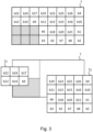
- Fig.3 represents an interleaving table T configured to perform data interleaving for communication in extended frequency band.
- the interleaving table T is obtained by concatenation of a first interleaving table T1 and a second interleaving table T2.
- the first interleaving table T is the input table of the interleaver used by the transmission method described on the Fig.2 and the interleaving tables T1 and T2 are output tables of the interleaver used for the transmission of the groups of distributed data to the various modulators, by the method executed.
- two modulators are used for the transmission of data in two frequency bands separate from the extended frequency band as defined.
- the interleaving tables T1 and T2 have respective dimensions (number of rows m i and of columns n i ) defined from the types of modulation used in each of the disjoint frequency bands of the extended frequency band.
- a first modulator uses a BPSK modulation (abbreviation for “Binary Phase Shift Keying”, in English) for the first frequency band and a second modulator uses a modulation of the QPSK type (abbreviation for “Quadrature Phase Shift Keying”) , in English).
- the interleaving table T1 corresponds to an interleaving table as defined, for example, according to the G3-PLC standard for BPSK modulation and its dimensions are defined by 2 rows and 3 columns.
- the interleaving table T2 corresponds to an interleaving table as defined, for example, according to the G3-PLC standard for QPSK modulation and its dimensions are defined by 4 rows and 5 columns.
- the dimensions of an interleaving table are defined so that the number of columns is equal to the number of subcarriers used in the frequency band used for data transmission and the number of rows depends the number of bits to interleave. This number of binary elements to be interleaved is therefore determined according to the number of binary elements coded by a symbol according to the type of modulation used, and by the number of sub-carriers used for the transmission of the symbols.
- the first interleaving table T is obtained by a concatenation of the second interleaving tables T1 and T2 which would be used for the interleaving of the data with a view to transmission in a single disjoint frequency band, respectively in BPSK for the second interleaving table T1 and in QPSK for the second interleaving table T2.
- Indices T1-11 to T1-13 index the different positions of the first line of the second interleaving table T1
- indices T1-21 to T1-23 index the different positions of the second line of the second interleaving table.
- indices T2-11 to T2-15 index the different positions of the first line of the second interleaving table T2
- indices T2-21 to T2-25 index the different positions of the second line of the second interleaving table T2
- indices T2-31 to T2-35 index the different positions of the third line of the second interleaving table T2
- indices T2-41 to T2-45 index the different positions of the fourth line of the second interleaving table T2.
- the aforementioned indices are not represented on the Fig.3 but can be used for a good understanding of the use of tables according to the embodiment described here.
- an index Ti [ m i , n i ] indexes, in the present description, a position at the m th line and the n th column of a table Ti.
- the previously cited indices therefore index the different positions of the interleaving table T obtained by concatenation of the interleaving tables T1 and T2, of the Fig. 3 to better illustrate the concatenation mode used.
- the concatenation of the second interleaving tables T1 and T2 is performed so that the table whose columns correspond to the lowest frequency subcarrier bands is located on the left.
- the second interleaving tables T1 and T2 are concatenated to define the first table T by matching the first line of the second interleaving table T1 with the first line of the second interleaving table T2, then the second line of the second interleaving table T1 with the second line of the second interleaving table T2.
- the definition of the first interleaving table T corresponds to the addition of the second interleaving table T1 and of the second interleaving table T2 to which is added a third interleaving table T' (represented in gray on the Fig. 3 ) so that the first interleaving table T has the same number of positions in each of its columns and in each of its rows.
- the positions included in the table T' are said to be “invalid” since, after an interleaving performed in the first interleaving table T, data (bits) could be moved to one of these positions.
- an interleaving operation in an interleaving table usually consists of shifting the content of each of the rows and columns a certain number of times by circular permutations of the binary elements contained in the positions of the table.
- Each row being conventionally shifted a number of times different from the other rows and each column being conventionally shifted a number of times different from the other columns.
- Binary elements b1 to b26 of a stream of binary elements are first "loaded” from left to right and from top to bottom into the first interleaving table T, prior to an interleaving operation, so that invalid positions are ignored.
- Binary element b1 is loaded in position T-11
- b2 is loaded in position T-12, ... b13 in position T-25, ... and b26 in position T-48.
- the invalid positions T-31, T-32, T-33, T-41, T-42 and T-43 of the first interleaving table T are ignored for the loading of bits b1 to b26.
- the first interleaving table T is thus obtained comprising the second interleaving tables T1 and T2, ready for an interleaving operation aimed at distributing the loaded data (bits b1 to b26) into several groups of data each assigned to a disjoint frequency band.
- the binary element b22 occupies for example the position occupied by the binary element b1 before the interleaving
- the binary element b24 occupies for example the position occupied by the binary element b2 before the interlacing
- the binary element b23 occupies for example the position occupied by the element b5 before the interlacing, ..., and so on.
- the interleaving having been carried out in entire rows and columns of the first interleaving table T, it follows that invalid positions may understand bits following interleaving. According to the embodiment, these elements are then moved to valid positions of the first interleaving table T.
- these movements are performed by traversing the invalid positions of the table T′ from top to bottom and from left to right. As soon as an invalid position comprises a binary element bi, the latter is moved to the first available valid position encountered by traversing the first interleaving table T from top to bottom and from left to right.
- each of the second interleaving tables T1 and T2 comprises a group of binary elements of the data divided into groups each corresponding to a disjoint frequency band included in the extended frequency band.
- the bits included in the second interleaving table T1 are transmitted to the first modulator with a view to transmission in BPSK in a first frequency band separate from the extended band
- the binary elements included in the second interleaving table T2 are transmitted to the second modulator with a view to transmission in QPSK in a second frequency band separate from the extended band.
- Each of the columns of the second interleaving tables corresponds to a sub-carrier of the frequency band allocated to the data group.
- the interleaving also operates a distribution of the data of each group on the various sub-carriers of the frequency band used for the transmission of the data of the group.
- the binary elements are respectively transmitted via serial streams to the modulators, via buffer memory zones (also called buffers or registers).
- the binary elements are in fact transmitted to input buffers respectively associated with the modulators, the input buffers of the modulators being directly the second interleaving tables T1 and T2.
- FIG.3 actually illustrates the division into groups of the first interleaving table T into two second interleaving tables T1 and T2 after the operations of interleaving and processing (moving) of the bits present at invalid positions, if any.
- This breakdown advantageously corresponds to the end of the interleaving useful for the distribution of the data to be transmitted in the extended frequency band, in the two disjoint frequency bands used according to the example described.
- the illustrated decomposition of the first interleaving table T into two second interleaving tables T1 and T2, at the end of the interleaving, constitutes an orientation of the data in the form of binary elements of each of the data groups (therefore of each of the second interleaving tables T1 and T2) to an electronic circuitry configured to modulate and transmit the binary elements.
- the electronic circuitry dedicated to each of the disjoint frequency bands notably comprises the modulator operating for transmission in this disjoint frequency band.
- the reasoning is similar as regards a distribution of data to be transmitted in three, four or even more disjoint frequency bands.
- the first interleaving table T (the largest) comprises as many second interleaving tables T1, T2, Ti as there are disjoint frequency bands included in the extended frequency band.
- the second interleaving tables T1, T2, Ti whose respective dimensions are defined according to the type of modulation used on each of the disjoint frequency bands included in the extended frequency band, are concatenated so that the table which includes the lowest sub-carriers is positioned on the left in the first interleaving table T, and the table which includes the highest sub-carriers is positioned on the right in the first interleaving table.
- Any second intermediate interleaving tables are arranged from left to right, in order of increasing frequency of the sub-carriers which they comprise.
- the first lines of each of the second tables T1, T2, Ti are aligned in the first upper line of the first interleaving table T.
- the matrix representation of the interleaving tables T, T1, T2 and of the table T' is intended to simplify the understanding of the arrangement of the data for the interleaving operations described, and each of the tables could be represented under form of a vector of binary elements, for example horizontal or vertical comprising segments delimiting the rows and columns previously described.
- the representation of the positions of the binary elements processed can be arbitrary, provided that the operations carried out on the binary elements correspond to the principles of interleaving previously described. Indeed, the positions of the binary elements in the tables conventionally correspond to cells of registers, or of random access memory of an electronic interleaving circuitry.
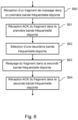
- Fig. 4 illustrates a method for transmitting a message M or a data frame in a hyper robust communication mode called "H-ROBO", according to a second mode of achievement.
- the message M must be transmitted according to the H-ROBO mode by a source node device (for example the node device 133) to a destination node device belonging to its network neighborhood (for example the node device 134).
- the two node devices 133 and 134 are configured to operate communications in multi-band mode and have operated protocol exchanges resulting in a choice of communication in hyper robust H-ROBO communication mode.
- the method starts in a step S400.
- the source node device 133 transmits to the destination node device 134 the message M on a first disjoint frequency band among the plurality of disjoint frequency bands comprising at least two frequency bands, the message M being modulated according to the mode of robust communication.
- the source node device 133 transmits to the destination node device 134 the same message M on a second disjoint frequency band among the plurality of disjoint frequency bands, the message M being, here again, modulated according to the robust mode. It should be noted that the second disjoint frequency band is different from the first disjoint frequency band.
- the first and second disjoint frequency bands are for example selected from a plurality of disjoint frequency bands defined in the G3-PLC standard, i.e. CENELEC A, CENELEC B, and ARIB or FCC.
- the first and second disjoint frequency bands are selected from a subset of the frequency bands defined in the G3-PLC standard, the subset comprising at least two disjoint frequency bands from among all the bands defined in the G3-PLC standard. PLC.
- the method ends in a step S430.
- the hyper-robust mode H-ROBO therefore uses different disjoint frequency bands by transmitting the same message M, or a data frame, simultaneously on these different frequency bands. In each frequency band, the robust mode is used.
- the hyper-robust mode is used when communication between neighboring nodes is difficult, e.g. when a value of an LQI quality indicator for the link in question is lower than a predetermined threshold value.
- the source node device 133 and the destination node device 134 are each based on LQI values received in tone map response information as defined in the G3-PLC standard to choose a transmission mode from among the multi-communication modes. strip (in ROBO mode in each strip) or in hyper-robust mode, and can therefore opt for different modes of communication.
- one of the node devices must adapt its transmission mode so that it is then compatible with the configuration mode chosen by the other node. Thus, it must be able to switch from multi-band transmission mode by fragmentation with ROBO-type modulation in each band to hyper-robust mode, if it detects that the other node device is communicating in hyper-robust H-ROBO mode. .
- FIG. 5 schematically illustrates a method for transmitting a message according to a third embodiment.
- a message M must be transmitted by a source node device (for example the node device 133) to a destination node device belonging to its network neighborhood (for example the node device 134).
- This embodiment is described in particular in connection with the G3-PLC communication standard. However, it is not limited to this single standard and could be applied to other standards, eg to the PRIME specifications (for “Powerline Intelligent Metering Evolution” in English), that is to say in particular in a communication network by carrier currents in line which does not present a mesh structure but which presents a tree structure.
- the method starts at a step S500.
- the message M which is for example encapsulated in an IP packet, eg an IPv6 packet (packet of size up to 1500 bytes), is fragmented into at least two fragments in order to adapt it to the constraints of the MAC layer, and in particular to the size of the MAC frames.
- an IP packet eg an IPv6 packet (packet of size up to 1500 bytes)
- IPv6 packet packet of size up to 1500 bytes
- the G3-PLC standard incorporates the 6LoWPAN protocol, which makes it possible to adapt IPv6 data packets to the constraints of the G3-PLC communication standard, in particular by fragmenting them.
- the MAC frames used by the G3-PLC standard are much smaller in size than the IPv6 packets of 1500 bytes (i.e. 400 bytes available at most per packet for the IP part).
- the adaptation layer of 6LoWPAN sits between the network layer and the MAC sublayer of the OSI model. It receives IPv6 packets of 1280 bytes from the network layer and fragments them if necessary. Of course, in the case of an IPv6 packet small enough to be contained in a single MAC G3-PLC frame, no fragmentation is performed. The method therefore applies in the case where the message M has such a length that it needs to be fragmented.
- Each fragment is generally preceded by a fragmentation header, for example a header comprising 4 or 5 bytes.
- This header contains for example the following information Five bits to identify that it is a fragment.
- the first fragment will have the value "11000” and the following "11100"; eleven bits to indicate the size of the IP packet before fragmentation (“datagram_size” field); sixteen bits to indicate an identifier (“datagram_tag” field) common to all the fragments of the same IP packet; and eight bits to indicate the position (“datagram_offset” field) of the fragment in the IP packet (only present in the fragments following the first).
- datagram_size eleven bits to indicate the size of the IP packet before fragmentation
- datagram_tag sixteen bits to indicate an identifier
- a first disjoint frequency band is associated with a first fragment among said at least two fragments resulting from the fragmentation of the message M, and a second disjoint frequency band, different from the first frequency band, is associated with the other of said at least two fragments.
- the associated first and second frequency bands are for example selected from the plurality of frequency bands defined in the G3-PLC communication standard, ie CENELEC A, CENELEC B, and ARIB or FCC.
- the first and second associated disjoint frequency bands are selected from a subset of the frequency bands defined in the G3-PLC communication standard, the subset comprising at least two bands from among all the bands authorized by G3-PLC .
- fragments originating from the same IP packet can be associated with a view to their transmission at different frequency bands.
- the embodiment described for two fragments can be extended to cases for which more than two fragments are defined, e.g. N fragments where N is a natural number.
- the same disjoint frequency band can be associated with different fragments.
- different disjoint frequency bands are then associated with at least two fragments of the message M among the N fragments.
- the disjoint frequency bands are associated alternately with the fragments.
- the first frequency band is associated with odd fragments (i.e. fragments 1, 3, 5, etc.) and the second frequency band is associated with even fragments (i.e. 2, 4, 6, etc).
- odd fragments i.e. fragments 1, 3, 5, etc.
- even fragments i.e. 2, 4, 6, etc.
- the fragment is transmitted on the frequency band associated with it.
- the transmission of a fragment on the medium ie on the power line, conventionally comprises various steps, in particular a segmentation of the fragments in order to adapt them to the physical layer and an OFDM modulation of the signal. Segmentation consists of partitioning a MAC (acronym for “Media Access Control”) frame into PSDUs (acronym for “PHY Service Data Unit”). All PSDUs from a single fragment are modulated using a single modulation scheme.
- MAC media Access Control
- PSDUs acronym for “PHY Service Data Unit”. All PSDUs from a single fragment are modulated using a single modulation scheme.
- FIG. 6 schematically illustrates a method of relaying a message M received by the first node device 133 from a third node device to the second node device 134, according to a fourth embodiment.
- this fourth embodiment at least two disjoint frequency bands are used in the same determined geographical area.
- the algorithm described by the flowchart of the Fig.6 is capable of being executed by each of the node devices of the communication network 120.
- the present algorithm is thus described below according to an example in which it is executed by the first node device 133, the second node device being the node device 134 and the third node device being the node device 137.
- the node device 133 receives from the node device 137 a fragment in a first disjoint frequency band.
- the transmission of a fragment on the medium, ie on the power line conventionally comprises various steps in particular a segmentation of the fragments in order to adapt them to the physical layer and an OFDM modulation of the signal. Segmentation consists of partitioning a MAC (acronym for “Media Access Control”) frame into PSDUs (acronym for “PHY Service Data Unit”). All PSDUs from a single fragment are modulated using a single modulation scheme.
- the node device 133 After demodulation and decoding of the received fragment according to the demodulation and decoding scheme of the first frequency band, disjoint, transmits an acknowledgment message to the node device 137.
- the node device 133 selects, from among the set of disjoint frequency bands, a second frequency band, different from the first frequency band and which is a frequency band on which the second node device 134 is capable of transmitting and receiving messages .
- the first node device 133 relays the fragment received from the third node device 137 to the second node device 134, after having operated a modulation and a coding of the decoded and demodulated fragment, according to the coding and modulation scheme of the disjoint frequency band selected.
- the first node device 133 receives an acknowledgment message from the second node device 134, recipient of the relayed message.
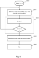
- Fig. 7 schematically illustrates a method for selecting at least one frequency band of the communication network for sending a message according to a fifth embodiment.
- the method described here can be executed each time a message M is sent by each node device which is capable of transmitting and receiving messages on several disjoint frequency bands of the communication network 120.
- the associated disjoint frequency bands are for example selected from the plurality of disjoint frequency bands defined in the G3-PLC communication standard, i.e. CENELEC A, CENELEC B, and ARIB or FCC.
- a node device for example the node device 133, has a message to send on the communication network 120.
- the node device 133 obtains a theoretical bit rate for each of the frequency bands disjoint on which the node device 133 is able to transmit and receive messages.
- each disjoint frequency band has, for each type of modulation used in this disjoint frequency band, a determined theoretical bit rate.
- the node device 133 obtains the theoretical throughput of each frequency band on which the node device 133 is capable of transmitting and receiving messages corresponding to the modulation used for sending the message to the node to which the message must be transferred.
- the node device 133 estimates, for each of the disjoint frequency bands, the theoretical transmission duration of the message in this disjoint frequency band, then during a step S74, the node device 133 interrogates a base of data to obtain results of integration of the occupancy rate of the disjoint frequency band corresponding to the theoretical transmission duration of the message in each frequency band.
- the node device 133 obtains, for each disjoint frequency band, a number of integration results during a first time scale corresponding to the theoretical transmission duration of the message in the disjoint frequency band concerned.
- the node device 133 also obtains a number of integration results during a second time scale corresponding to the time at which the message is to be sent.
- the node device 133 finally obtains a number of results integration during a third time scale corresponding to the day on which the message must be sent.
- the node device 133 selects the disjoint frequency band from among the disjoint frequency bands for which the occupancy rate integration results are the lowest. For example, the node device 133 calculates, for each disjoint frequency band, the mean of the integration results during the first, second and third time scales and selects the disjoint frequency band for which the calculated mean is the lowest.
- a weighting coefficient is assigned to the integration results during the first, second and third time scales before the calculation of the average. For example, a weighting of 10 is assigned to the integration results during the first timescale, a weighting of 12 is assigned to the integration results during the second timescale, and a weighting of 7 is assigned to the integration results during the third timescale.
- Fig. 8 schematically illustrates a method for selecting a communication route between a first node device and a second node device of the communication network 120, of the electrical power supply mesh network type using line carrier communications, according to a sixth mode of achievement.
- the second node device e.g. the node 132
- the second node device is reachable from the first node device, e.g. 133, by at least a first communication route, e.g. the route passing through the nodes 130, 131 and a second communication route, e.g. passing through nodes 134, 135 and 136, different from said first communication route.
- the second node device is reachable from the first node device by a plurality of N communication routes, N being a positive integer.
- N being a positive integer.
- each possible route is identified by an index k with k integer varying from 0 to N-1.
- the method starts at a step S800 where k is equal to zero.
- the second node device obtains a route cost RCk for a communication route of index k among the plurality of N communication routes.
- the route cost RC k is equal to the sum of the link costs LC i,j between two successive node devices i and j, ie located in the same network neighborhood.
- the cost of the route RCi L 133.130 +L 130.131 +L 131.132 .
- the cost RC 2 of the second communication route are equal to L 133.134 +L 134.135 +L 135.136 + L 136.132 .
- the cost of an LC link i,j between two successive node devices is a function of the maximum value among a cost of the LC link i ⁇ j in the forward direction, ie from the transmitter node device to the receiver node device, and a cost of the link LC j ⁇ i in the backward direction, ie from the receiver node device to the transmitter node device.
- adpKrt has a value of 0 and adpKh has a value of 4.
- the second node device will be able to compare the potential routes, and define a preference for the one with the fewest hops.
- a specific metric is defined to determine the costs of the directional links in order to adapt to node devices which have transmission capacities of the multi-band type.
- a node device has multi-band capabilities in the case where it is configured to be able to simultaneously use several disjoint frequency bands, eg CENELEC-A and FCC, instead of choosing and operating in a single disjoint frequency band.
- the node device in question may fragment the message into different fragments according to the 6LoWPAN protocol. The fragmentation process is more particularly described in section 5.3 of the RFC 4944 recommendation (published in September 2007). Each fragment is then sent independently of the other fragments on frequency bands which may be different.
- the associated frequency bands are for example selected from the set of frequency bands authorized by G3-PLC, ie CENELEC A, CENELEC B, ARIB and FCC.
- the associated first and second frequency bands are selected from a subset of the frequency bands authorized by G3-PLC, the subset comprising at least two bands from among all the bands authorized by G3-PLC.
- a node device having multi-band capabilities can transmit the same message simultaneously in all frequency bands of the set of frequency bands supported (by transmitter and receiver). This mode of transmission is called in the following the hyper-robust mode.
- the robust mode of G3-PLC is then used. In this way, in the event of a large frequency disturbance on a frequency band, the message can nevertheless succeed in passing over to another frequency band. Indeed, the receiver only needs to succeed in picking up the message on only one of the frequency bands on which it was transmitted.
- the hyper-robust mode is a particular mode newly defined for the case of node devices having multi-band capacities.
- a node device having multi-band capabilities can transmit a message over all of the frequency bands, which then constitute a so-called extended frequency band.
- the multi-band capacity of a node device is characterized by the fact that the node is capable of exploiting several frequency bands simultaneously instead of a single and unique band as is conventionally the case. in the case of the G3-PLC standard.
- a device having multi-band capabilities can benefit from the characteristics of the different frequency bands in terms of bit rate, range, resistance to disturbances.
- the route cost as defined by G3-PLC in its appendix D does not make it possible to take account of these multi-band capacities of the node device. Indeed, the G3-PLC communication standard only allows the use of a single frequency band for a given network. According to a particular embodiment, the cost of the link LC i ⁇ j in a given direction, ie in the forward or reverse direction, depends on the cost of the link, in said given direction, calculated for each frequency band LC i ⁇ j [m] of the set of frequency bands used by said two successive node devices i and j to communicate, said set comprising at least two different frequency bands.
- the index k is incremented by 1 and compared to N-1 during a step S820, k is incremented by 1 and compared to N-1. If k is less than or equal to N-1 then the method continues at step S810, otherwise it continues at step S830.
- the second node device selects, among said N communication routes, the communication route corresponding to the lowest route cost.
- the process of Fig. 8 ends at step S840.
- a cost LC i ⁇ j of a directional link between a first node device and a second node device is calculated from a cost LC i ⁇ j [m] of a directional link per disjoint frequency band, m being an index identifying the frequency band, and m is an integer varying from 0 to NBP-1, where NBP is an integer equal to the number of usable disjoint frequency bands. For example, NBP can be equal to 4.
- an index m equal to 0 corresponds to the CENELEC-A band
- an index m equal to 1 corresponds to the FCC band
- an index m equal to 2 corresponds to the band CENELEC-B
- an m index equal to 3 corresponds to the ARIB band.
- This process starts at step S8100 when m is zero.
- m is incremented by 1 and compared to the number NBP-1. If m is less than or equal to NBP-1 then the process continues at step S8110, otherwise it continues in sequence at step S8130.
- step S8140 subsequent to step 8130, the overall directional cost LC i ⁇ j is calculated.
- the hyper-robust mode is not used in equations (1) and (2) and adpKhr has a zero value.
- the calculation process then ends at a final step S8150.
- Steps S8100 to S8150 are repeated to calculate the global directional cost Lc j ⁇ i and thus to deduce therefrom the cost LC i,j .
- Steps S8100 to S8150 are not represented on the Fig. 8 but can be used as references for a good understanding of the method for calculating the cost LC i,j of a link described above, in particular because of the possible looping between steps S8120 and S8110.
- FIG. 9 illustrates a method for determining a mode of communication between two node devices neighboring each other in the communication network 120, according to a seventh embodiment.
- These node devices are, by way of example, the node device 133 operating as an initiator node device and the neighbor node device 134, operating as a target node device.
- the node devices 133 and 134 are configured to communicate with each other according to at least one mode of communication in at least one disjoint frequency band. It is considered that the node devices 133 and 134 are then normally operational at this point and that an exchange of messages can be initiated.
- the initiator node device 133 sends, in step S91, a message comprising information according to which a request for channel estimation in an extended frequency band EB is requested to the target node device, and waits for a predetermined time for a possible message in response. At the end of the predetermined period, the initiator node device 133 checks in step S912, whether a response has indeed been received in the form of a message comprising information representative of a channel estimate in the frequency band EB.
- the initiator node device 133 records in step S95 the information received and representative of a channel estimate in the extended frequency band EB, in its neighborhood table NT-REC, and determines a preferred mode of communication, taking into account in particular the various information available in the neighborhood table NT-REC. For example, the initiator node device 133 determines that the extended frequency band communication mode EB is the most advantageous communication mode at this moment to communicate with the target node device 134, and initiates a transmission in this mode there, in the extended frequency band EB, in step S96.
- the initiator node device 133 in the absence of a response from the target node device 134 after a predetermined time, the initiator node device 133 considers that the target node device 134 does not support communication according to an in-band communication mode. extended and sends, during steps S92 and S93, messages respectively comprising a request for channel estimation in the frequency band B1 and a request for channel estimation in the frequency band B2. The initiator node device 133 then waits for a possible response to at least one of these two messages, or to each of these two messages, and records the information representative of one or more channel estimates, received in response, in one or more several neighborhood tables NT-REC, before communicating later in step S6.
- the method resumes at step S92 and the initiator node device again sends messages to the target node device, until a response is obtained in at least one of the two frequency bands B1 and B2.
- a new message comprising a channel estimation request (TMR indicator set to 1, for example, in G3-PLC) can be sent as soon as data must be transmitted to the target node device 134.
- step S6 When communications are established in step S6, in a determined communication mode between the two node devices, and in the absence of a communication problem detected during a step S962 aimed at defining a communication quality level, the communications continue according to the selected communication mode. Conversely, if a communication quality problem is detected, the determination process is restarted from step S91.
- the determination of the transmission mode comprises a step of comparing first transmission quality indicators respectively determined, for each of the frequency bands, from the recorded information associated with each of the at least two frequency bands B1 and B2.
- the determination of the transmission mode may further comprise a selection of a so-called "robust” transmission mode. » using BPSK modulation and systematic repetition of the transmitted bits (for example, each bit is repeated four times or six times during a transmission).
- the selection of a so-called "robust” transmission mode depends, for example, on a level of transmission quality defined from an estimate of a transmission channel established via a multi-band transmission in said at least two frequency bands B1 and B2.
- Fig. 10 schematically illustrates an example of the internal architecture of any node device of the communication network 120.
- the Fig. 10 illustrates an internal arrangement of the node device 133.
- Such a node device is qualified as multi-band because it is capable of transmitting a message on several disjoint frequency bands used in parallel.
- the Fig. 10 could also schematically illustrate an example of hardware architecture of a processing module included in the node device 133.
- the node device 133 then comprises, connected by a communication bus 1300: a processor or CPU (Central Processing Unit) 1331; a random access memory RAM (Random Access Memory) 1332; a read-only memory ROM 1333; a storage unit such as a hard disk (or a storage medium reader, such as an SD ("Secure Digital" in English) card reader 1334; at least one communication interface 1335 allowing the node device 133 to communicate with the node devices belonging to its network neighborhood, such as, for example, the node devices 134 and 137.
- a communication bus 1300 a processor or CPU (Central Processing Unit) 1331; a random access memory RAM (Random Access Memory) 1332; a read-only memory ROM 1333; a storage unit such as a hard disk (or a storage medium reader, such as an SD ("Secure Digital" in English) card reader 1334; at least one communication interface 1335 allowing the node device 133 to communicate with the node devices belonging to its network neighborhood, such as
- Processor 1301 is capable of executing instructions loaded into RAM 1332 from ROM 1333, external memory (not shown), storage media (such as an SD card), or a communications network. When the node device is powered up, processor 1331 is able to read instructions from RAM 1332 and execute them. These instructions form a computer program causing the implementation, by the processor 1331, of all or part of the exchanges and methods described in relation to the aforementioned figures illustrating a method according to an embodiment previously described.
- node device 133 includes electronic circuitry configured to implement the methods described in connection with node device 133 (likewise for node device 134).
- Fig. 11 schematically illustrates an example of multi-band reception architecture. More particularly, a reception processing chain 1120 of a node device is illustrated, such as the node device 134.
- the reception processing chain 1120 comprises two demodulators DEM 1 1124 and DEM2 1126 and can therefore process a band, multi-band or extended frequency band (here with the conjunction of two disjoint frequency bands).
- the processing chain 1120 comprises a programmable gain stage AMP 1121 configured to support all the input dynamics of the multiple frequency bands and to avoid possible saturation of the signals of one of the disjoint frequency bands.
- An analog-digital conversion stage ECH 1122 performs the conversion and controls the gain of the programmable gain stage AMP 21.
- the ECH conversion stage 22 is shared and the sampling frequency is defined with respect to the frequency of sampling required in the disjoint frequency band having the highest frequency.
- the separation of the data transmitted in the different frequency bands is then carried out with digital filters F1 1123 and F2 1125 respectively.
- the frequency bands being disjoint, their respective signals can be easily distinguished in this way.
- the data at the output of each of the digital filters F1 and F2 are then respectively transmitted to the demodulators DEM1 1124 and DEM2 1126.
- the output of the demodulators DEM1 1124 and DEM2 1126 is processed by an FEC decoder 1128, via a first memory MEM1 1127, called deinterleaving memory.
- the data is loaded according to a predefined arrangement so as to be able to deinterleave them according to several deinterleaving modes which correspond to the inverse of the interleaving operations carried out on transmission.
- An FEC decoder deinterleave circuit 1128 reads the data from the first deinterleave memory MEM1 1127 and is configured to check whether the deinterleaved data appears coherent.
- the deinterleaved data appear coherent, they are recorded in a second memory MEM2 1129, called the reception memory of the MAC link sub-layer.
- the data thus stored in the reception memory MEM2 1129 constitute data frames ready to be processed by the MAC layer of the ISO model.
- the consistency of the data deinterleaved according to a deinterleaving mode specific to an extended frequency band transmission is first checked. If the data is not coherent, this means that another mode of transmission has been used for the transmission of the data and a second deinterleaving operation, by means of each of the single-band deinterleaving tables is carried out.
- the architecture presented is not limiting, and a node device can comprise, for example, three or more demodulators (and their corresponding filters), depending on the number of frequency bands in which it must be able to perform data reception.
- the methods described above according to the various embodiments are particularly advantageous in the context of a mesh network of the G3-PLC type to increase the communication performance between node devices of such a network.
- a node device being configured to transmit in an extended frequency band can also use a multi-band communication mode implementing a fragmentation of a message, each fragment being capable of being transmitted on a frequency band disjoint among those usable.
- a node device configured to implement a method of optimizing the transmission time can also be configured to optimize the bandwidth on the communication network in which it operates.
Claims (11)
- Verfahren zur Übertragung von Daten in Form von Nachrichten in einem Powerline-Kommunikationsnetz (120),
wobei das Verfahren in einer ersten Knotenvorrichtung (133) des Netzes (120) ausgeführt wird, die dazu konfiguriert ist, in mehreren getrennten Frequenzbändern mit einer zweiten Knotenvorrichtung (134) des Netzes (120) zu kommunizieren, wobei das Verfahren das Senden einer Nachricht in einem Übertragungsmodus unter paralleler Verwendung von mindestens zwei getrennten Frequenzbändern aus den mehreren getrennten Frequenzbändern umfasst und wobei das Verfahren dadurch gekennzeichnet ist, dass das Senden einer Nachricht in einem Übertragungsmodus unter paralleler Verwendung von mindestens zwei getrennten Frequenzbändern die Verwendung eines sogenannten Frequenzbands umfasst, das als erweitertes Frequenzband bezeichnet wird und mindestens zwei getrennte Frequenzbänder aus den mehreren getrennten Frequenzbändern umfasst, wobei jedes getrennte Frequenzband mehrere Unterträger umfasst, wobei das Verfahren ferner einen Schritt des Verschachtelns von Daten einer zu übertragenden Nachricht umfasst, der für ein Senden der auf alle Unterträger verteilten Daten ausgelegt ist. - Verfahren nach Anspruch 1, wobei der Schritt des Verschachtelns der Daten Folgendes umfasst:
Erhalten einer ersten Verschachtelungstabelle T [m, n] von Binärelementen, die für die zu übertragenden Daten repräsentativ sind, wobei die erste Verschachtelungstabelle so viele zweite Verschachtelungstabellen Ti [mi , ni ] von Binärelementen umfasst, wie getrennte Frequenzbänder im erweiterten Band enthalten sind, wobei jede zweite Verschachtelungstabelle Ti [mi , ni ] nur einem der mindestens zwei getrennten Frequenzbänder des erweiterten Frequenzbands zugeordnet ist, wobei die Abmessungen mi , ni jeder der zweiten Verschachtelungstabellen Ti [mi , ni ] gemäß einem Modulationstyp definiert sind, der für das Senden der Daten im getrennten Frequenzband, dem eine zweite Verschachtelungstabelle zugeordnet ist, verwendet wird, wobei etwaige Differenzen in den Abmessungen zwischen zweiten Verschachtelungstabellen geeignet sind, eine oder mehrere sogenannte ungültige Positionen zu erzeugen, die in der ersten Verschachtelungstabelle enthalten sind, aber nicht in der mindestens einer der zweiten Verschachtelungstabellen enthalten sind,- Verschachteln der Binärelemente durch aufeinanderfolgende Verschiebungen der Zeilen m und der Spalten n der ersten Verschachtelungstabelle T [m, n], wobei die aufeinanderfolgenden Verschiebungen in Form von kreisförmigen Permutationen der Binärelemente pro Zeile bzw. pro Spalte erfolgen,- Bewegen jedes Binärelements, das als an einer ungültigen Position der ersten Verschachtelungstabelle vorhanden erkannt wurde, in eine Position einer zweiten Verschachtelungstabelle, die nach der Verschiebung der Binärelemente der ersten Verschachtelungstabelle verfügbar ist, sodass jede zweite Verschachtelungstabelle Binärelemente enthält, die einer der Datengruppen zugeordnet ist,- Ausrichten der Binärelemente jeder der Datengruppen auf eine elektronische Schaltungsanordnung, die dazu konfiguriert ist, die Binärelemente zu modulieren und zu übertragen. - Verfahren nach Anspruch 1, wobei das Verfahren vor der Übertragung der Nachricht die folgenden Schritte umfasst:- für jedes getrennte Frequenzband Schätzen einer Dauer für die Übertragung der Nachricht in diesem Frequenzband,- aus einer Datenbank Erhalten von Ergebnissen der Integration von Belegungsgraden jedes Frequenzbands, die während mehrerer Zeitskalen bestimmt wurden, die der theoretischen Sendedauer der Nachricht in jedem Frequenzband entsprechen,- Auswählen eines Frequenzbands aus den erhaltenen Ergebnissen der Integration von Belegungsgraden jedes Frequenzbands, die während mehrerer Zeitskalen bestimmt wurden, und- Übertragen der Nachricht im ausgewählten Frequenzband.
- Verfahren nach Anspruch 1, wobei die zweite Knotenvorrichtung (134) von der ersten Knotenvorrichtung (133) über mindestens zwei verschiedene Kommunikationsstrecken erreichbar ist, wobei das Verfahren Folgendes umfasst:- Erhalten von Streckenkosten für jede der Kommunikationsstrecken und- Auswählen der Kommunikationsstrecke aus den Kommunikationsstrecken, die den geringsten Streckenkosten entspricht.
- Verfahren nach einem der Ansprüche 1 bis 4, wobei das Verfahren die folgenden Schritte umfasst:- Übertragen eines Exemplars einer ersten Nachricht an die zweite Knotenvorrichtung (134) in jedem der mindestens zwei getrennten Frequenzbänder, wobei die erste Nachricht eine Information enthält, dass durch die erste Knotenvorrichtung (133) eine Kanalschätzung von der zweiten Knotenvorrichtung (134) angefordert wird,- Empfangen einer zweiten Nachricht, die durch die zweite Knotenvorrichtung (134) auf jedem getrennten Frequenzband, über das die zweite Knotenvorrichtung (134) ein Exemplar der ersten Nachricht empfangen hat, gesendet wurde, wobei jede zweite Nachricht Informationen umfasst, die für eine Kanalschätzung für das getrennte Frequenzband, über das die zweite Nachricht empfangen wurde, repräsentativ sind,- Aufzeichnen der in jeder empfangenen zweiten Nachricht enthaltenen Informationen, die die Kanalschätzung darstellen, durch die erste Knotenvorrichtung (133) und- anhand der aufgezeichneten Informationen Bestimmen eines Übertragungsmodus einer dritten Nachricht, die später von der ersten Knotenvorrichtung (133) an die zweite Knotenvorrichtung (134) zu senden ist.
- Verfahren nach einem der vorangehenden Ansprüche, wobei die mindestens zwei getrennten Frequenzbänder aus folgender Gruppe stammen: CENELEC-A-Frequenzband, CENELEC-B-Frequenzband und FCC-Frequenzband oder ARIB-Frequenzband.
- Verfahren nach einem der vorangehenden Ansprüche, wobei das Powerline-Kommunikationsnetz ein Maschennetz vom Typ G3-PLC ist.
- Knotenvorrichtung (133) zur Verwendung in einem Powerline-Kommunikationsnetz (120), wobei die Knotenvorrichtung (133) dazu konfiguriert ist, in mehreren getrennten Frequenzbändern mit einer zweiten Knotenvorrichtung (134) des Netzes (120) zu kommunizieren und einen Übertragungsmodus parallel in mindestens zwei getrennten Frequenzbändern aus mehreren getrennten Frequenzbändern anzuwenden, wobei die Knotenvorrichtung (133) dadurch gekennzeichnet ist, dass sie dazu konfiguriert ist, die Nachricht in einem Übertragungsmodus unter paralleler Verwendung von mindestens zwei getrennten Frequenzbändern mit Verwendung eines Frequenzbands, das als erweitertes Frequenzband bezeichnet wird und mindestens zwei getrennte Frequenzbänder aus den mehreren getrennten Frequenzbändern umfasst, zu senden, wobei jedes getrennte Frequenzband mehrere Unterträger umfasst, wobei die Knotenvorrichtung (133) eine Verschachtelungsschaltungsanordnung zum Verschachteln der Daten einer zu sendenden Nachricht umfasst, die für ein Senden der auf alle Unterträger verteilten Daten ausgelegt ist.
- Powerline-Kommunikationsnetz (120), umfassend mehrere Knotenvorrichtungen nach Anspruch 8.
- Computerprogrammprodukt, dadurch gekennzeichnet, dass es Programmcodeanweisungen umfasst, um die Schritte des Verfahrens nach einem der Ansprüche 1 bis 7 auszuführen, wenn das Programm durch einen Prozessor ausgeführt wird.
- Informationsspeichermedium, umfassend ein Computerprogrammprodukt nach dem vorangehenden Anspruch.
Applications Claiming Priority (1)
| Application Number | Priority Date | Filing Date | Title |
|---|---|---|---|
| FR2006950A FR3112260A1 (fr) | 2020-07-01 | 2020-07-01 | Procede de transmission dans plusieurs bandes frequentielles entre deux dispositifs voisins d’un reseau. |
Publications (2)
| Publication Number | Publication Date |
|---|---|
| EP3934113A1 EP3934113A1 (de) | 2022-01-05 |
| EP3934113B1 true EP3934113B1 (de) | 2023-08-02 |
Family
ID=73013569
Family Applications (1)
| Application Number | Title | Priority Date | Filing Date |
|---|---|---|---|
| EP21181359.7A Active EP3934113B1 (de) | 2020-07-01 | 2021-06-24 | Verfahren zur übertragung in mehreren frequenzbändern zwischen zwei benachbarten geräten in einem netzwerk |
Country Status (2)
| Country | Link |
|---|---|
| EP (1) | EP3934113B1 (de) |
| FR (1) | FR3112260A1 (de) |
Family Cites Families (5)
| Publication number | Priority date | Publication date | Assignee | Title |
|---|---|---|---|---|
| US20120134395A1 (en) * | 2010-11-30 | 2012-05-31 | Texas Instruments Incorporated | Power Line Communications (PLC) Across Different Voltage Domains Using Multiple Frequency Subbands |
| US20120189042A1 (en) * | 2011-01-11 | 2012-07-26 | Texas Instruments Incorporated | Building, Transmitting, and Receiving Robust Protocol Data Units in Power Line Communications |
| US9231657B2 (en) * | 2012-01-13 | 2016-01-05 | Texas Instruments Incorporated | Adaptive sub-band algorithm for point-to-point communication in PLC networks |
| US10686914B2 (en) * | 2014-11-04 | 2020-06-16 | Texas Instruments Incorporated | Automatic selection of MAC protocol to support multiple prime PLC standards |
| FR3036566B1 (fr) * | 2015-05-20 | 2019-07-19 | Sagemcom Energy & Telecom Sas | Procede de selection d'un filtre a appliquer en reception d'une trame |
-
2020
- 2020-07-01 FR FR2006950A patent/FR3112260A1/fr not_active Withdrawn
-
2021
- 2021-06-24 EP EP21181359.7A patent/EP3934113B1/de active Active
Also Published As
| Publication number | Publication date |
|---|---|
| EP3934113A1 (de) | 2022-01-05 |
| FR3112260A1 (fr) | 2022-01-07 |
Similar Documents
| Publication | Publication Date | Title |
|---|---|---|
| EP1878185B1 (de) | Verfahren zur Kodierung eines OFDM/OQAM-Signals unter Verwendung von Symbolen mit komplexen Werten und entsprechendes Signal, Einrichtungen und Computerprogramme | |
| FR2929063A1 (fr) | Procede et dispositif d'allocation de chemins de transmission de donnees dans un reseau de communication synchrone, produit programme d'ordinateur et moyen de stockage correspondants | |
| EP3934108B1 (de) | Verfahren zur bestimmung eines kommunikationsmodus zwischen zwei benachbarten geräten in einem netzwerk | |
| EP3934109B1 (de) | Verfahren und vorrichtung zur übertragung einer nachricht | |
| EP3934111B1 (de) | Verfahren zur auswahl eines kommunikationsweges | |
| EP3934113B1 (de) | Verfahren zur übertragung in mehreren frequenzbändern zwischen zwei benachbarten geräten in einem netzwerk | |
| FR3072529A1 (fr) | Routage de donnees dans une passerelle residentielle mettant en œuvre l'agregation de liens | |
| EP3934112B1 (de) | Empfangsverfahren und -kette für plc-modem | |
| EP3934106B1 (de) | Verfahren zur breitbandübertragung zwischen zwei benachbarten vorrichtungen in einem netzwerk | |
| FR3126578A1 (fr) | Procede de regulation destine a resorber un engorgement d’un reseau maille de communication par courants porteurs en ligne et radio | |
| EP4142247A1 (de) | Übertragungsverfahren und knotenvorrichtung für die implementierung dieses verfahrens | |
| WO2000028662A1 (fr) | Filtre numerique a architecture parallele et recepteur de signaux a etalement de spectre utilisant un tel filtre | |
| EP3934107A1 (de) | Nachrichtenübertragungsverfahren und -vorrichtung | |
| FR2944941A1 (fr) | Procede de calcul du cout d'un lien de communication entre des noeuds d'un reseau de communication | |
| EP4142169A1 (de) | Übertragungsverfahren und knotenvorrichtung für die implementierung dieses verfahrens | |
| FR3109852A1 (fr) | Procede et dispositif de relai d’un message recu d’un premier dispositif par un deuxieme dispositif nœud vers un troisieme dispositif noeud | |
| EP0767550A1 (de) | Interbandfrequenzsprungverfahren in einer zellulare Funkkommunikationsanordnung mit mobilen Stationen und Stationen dafür | |
| FR2895626A1 (fr) | Routage et optimisation du debit point a point dans un reseau ad hoc multisauts | |
| WO2024002898A1 (fr) | Procédé de retransmission coopérative dans un système omamrc | |
| WO2024079309A1 (fr) | Procédé de retransmission coopérative dans un système omamrc avec allocation de ressources et sélections des sources à aider conjointes | |
| EP4142246A1 (de) | Verfahren zur erkennung von benachbarten knoten, die zur kommunikation über leitungsgebundene trägerströme und über einen funkkanal geeignet sind | |
| WO2023275469A1 (fr) | Procede de retransmission cooperative dans un systeme omamrc | |
| WO2006069872A1 (fr) | Procédé et dispositif d'émission d'un signal multiporteuse avec décalage temporel d'un sous-ensemble d'éléments de symbole, signal, procédé et dispositif de réception correspondants | |
| FR2855000A1 (fr) | Procede de reception d'un signal multiporteuse mettant en oeuvre une determination du format du filtrage de mise en forme et recepteur correspondant | |
| CA2251630A1 (fr) | Procede de transmission de signaux numeriques par frequences correllees |
Legal Events
| Date | Code | Title | Description |
|---|---|---|---|
| PUAI | Public reference made under article 153(3) epc to a published international application that has entered the european phase |
Free format text: ORIGINAL CODE: 0009012 |
|
| STAA | Information on the status of an ep patent application or granted ep patent |
Free format text: STATUS: REQUEST FOR EXAMINATION WAS MADE |
|
| 17P | Request for examination filed |
Effective date: 20210624 |
|
| AK | Designated contracting states |
Kind code of ref document: A1 Designated state(s): AL AT BE BG CH CY CZ DE DK EE ES FI FR GB GR HR HU IE IS IT LI LT LU LV MC MK MT NL NO PL PT RO RS SE SI SK SM TR |
|
| B565 | Issuance of search results under rule 164(2) epc |
Effective date: 20211207 |
|
| RBV | Designated contracting states (corrected) |
Designated state(s): AL AT BE BG CH CY CZ DE DK EE ES FI FR GB GR HR HU IE IS IT LI LT LU LV MC MK MT NL NO PL PT RO RS SE SI SK SM TR |
|
| STAA | Information on the status of an ep patent application or granted ep patent |
Free format text: STATUS: EXAMINATION IS IN PROGRESS |
|
| 17Q | First examination report despatched |
Effective date: 20220729 |
|
| GRAP | Despatch of communication of intention to grant a patent |
Free format text: ORIGINAL CODE: EPIDOSNIGR1 |
|
| STAA | Information on the status of an ep patent application or granted ep patent |
Free format text: STATUS: GRANT OF PATENT IS INTENDED |
|
| INTG | Intention to grant announced |
Effective date: 20230316 |
|
| GRAS | Grant fee paid |
Free format text: ORIGINAL CODE: EPIDOSNIGR3 |
|
| GRAA | (expected) grant |
Free format text: ORIGINAL CODE: 0009210 |
|
| STAA | Information on the status of an ep patent application or granted ep patent |
Free format text: STATUS: THE PATENT HAS BEEN GRANTED |
|
| AK | Designated contracting states |
Kind code of ref document: B1 Designated state(s): AL AT BE BG CH CY CZ DE DK EE ES FI FR GB GR HR HU IE IS IT LI LT LU LV MC MK MT NL NO PL PT RO RS SE SI SK SM TR |
|
| REG | Reference to a national code |
Ref country code: GB Ref legal event code: FG4D Free format text: NOT ENGLISH |
|
| REG | Reference to a national code |
Ref country code: CH Ref legal event code: EP |
|
| REG | Reference to a national code |
Ref country code: DE Ref legal event code: R096 Ref document number: 602021003921 Country of ref document: DE |
|
| REG | Reference to a national code |
Ref country code: IE Ref legal event code: FG4D Free format text: LANGUAGE OF EP DOCUMENT: FRENCH |
|
| REG | Reference to a national code |
Ref country code: LT Ref legal event code: MG9D |
|
| REG | Reference to a national code |
Ref country code: NL Ref legal event code: MP Effective date: 20230802 |
|
| REG | Reference to a national code |
Ref country code: AT Ref legal event code: MK05 Ref document number: 1595980 Country of ref document: AT Kind code of ref document: T Effective date: 20230802 |
|
| REG | Reference to a national code |
Ref country code: DE Ref legal event code: R082 Ref document number: 602021003921 Country of ref document: DE Representative=s name: PUSCHMANN BORCHERT KAISER KLETTNER PATENTANWAE, DE |
|
| PG25 | Lapsed in a contracting state [announced via postgrant information from national office to epo] |
Ref country code: GR Free format text: LAPSE BECAUSE OF FAILURE TO SUBMIT A TRANSLATION OF THE DESCRIPTION OR TO PAY THE FEE WITHIN THE PRESCRIBED TIME-LIMIT Effective date: 20231103 |
|
| PG25 | Lapsed in a contracting state [announced via postgrant information from national office to epo] |
Ref country code: IS Free format text: LAPSE BECAUSE OF FAILURE TO SUBMIT A TRANSLATION OF THE DESCRIPTION OR TO PAY THE FEE WITHIN THE PRESCRIBED TIME-LIMIT Effective date: 20231202 |
|
| PG25 | Lapsed in a contracting state [announced via postgrant information from national office to epo] |
Ref country code: SE Free format text: LAPSE BECAUSE OF FAILURE TO SUBMIT A TRANSLATION OF THE DESCRIPTION OR TO PAY THE FEE WITHIN THE PRESCRIBED TIME-LIMIT Effective date: 20230802 Ref country code: RS Free format text: LAPSE BECAUSE OF FAILURE TO SUBMIT A TRANSLATION OF THE DESCRIPTION OR TO PAY THE FEE WITHIN THE PRESCRIBED TIME-LIMIT Effective date: 20230802 Ref country code: PT Free format text: LAPSE BECAUSE OF FAILURE TO SUBMIT A TRANSLATION OF THE DESCRIPTION OR TO PAY THE FEE WITHIN THE PRESCRIBED TIME-LIMIT Effective date: 20231204 Ref country code: NO Free format text: LAPSE BECAUSE OF FAILURE TO SUBMIT A TRANSLATION OF THE DESCRIPTION OR TO PAY THE FEE WITHIN THE PRESCRIBED TIME-LIMIT Effective date: 20231102 Ref country code: NL Free format text: LAPSE BECAUSE OF FAILURE TO SUBMIT A TRANSLATION OF THE DESCRIPTION OR TO PAY THE FEE WITHIN THE PRESCRIBED TIME-LIMIT Effective date: 20230802 Ref country code: LV Free format text: LAPSE BECAUSE OF FAILURE TO SUBMIT A TRANSLATION OF THE DESCRIPTION OR TO PAY THE FEE WITHIN THE PRESCRIBED TIME-LIMIT Effective date: 20230802 Ref country code: LT Free format text: LAPSE BECAUSE OF FAILURE TO SUBMIT A TRANSLATION OF THE DESCRIPTION OR TO PAY THE FEE WITHIN THE PRESCRIBED TIME-LIMIT Effective date: 20230802 Ref country code: IS Free format text: LAPSE BECAUSE OF FAILURE TO SUBMIT A TRANSLATION OF THE DESCRIPTION OR TO PAY THE FEE WITHIN THE PRESCRIBED TIME-LIMIT Effective date: 20231202 Ref country code: HR Free format text: LAPSE BECAUSE OF FAILURE TO SUBMIT A TRANSLATION OF THE DESCRIPTION OR TO PAY THE FEE WITHIN THE PRESCRIBED TIME-LIMIT Effective date: 20230802 Ref country code: GR Free format text: LAPSE BECAUSE OF FAILURE TO SUBMIT A TRANSLATION OF THE DESCRIPTION OR TO PAY THE FEE WITHIN THE PRESCRIBED TIME-LIMIT Effective date: 20231103 Ref country code: FI Free format text: LAPSE BECAUSE OF FAILURE TO SUBMIT A TRANSLATION OF THE DESCRIPTION OR TO PAY THE FEE WITHIN THE PRESCRIBED TIME-LIMIT Effective date: 20230802 Ref country code: AT Free format text: LAPSE BECAUSE OF FAILURE TO SUBMIT A TRANSLATION OF THE DESCRIPTION OR TO PAY THE FEE WITHIN THE PRESCRIBED TIME-LIMIT Effective date: 20230802 |
|
| PG25 | Lapsed in a contracting state [announced via postgrant information from national office to epo] |
Ref country code: PL Free format text: LAPSE BECAUSE OF FAILURE TO SUBMIT A TRANSLATION OF THE DESCRIPTION OR TO PAY THE FEE WITHIN THE PRESCRIBED TIME-LIMIT Effective date: 20230802 |