EP3934091A1 - Power conversion device - Google Patents
Power conversion device Download PDFInfo
- Publication number
- EP3934091A1 EP3934091A1 EP19918119.9A EP19918119A EP3934091A1 EP 3934091 A1 EP3934091 A1 EP 3934091A1 EP 19918119 A EP19918119 A EP 19918119A EP 3934091 A1 EP3934091 A1 EP 3934091A1
- Authority
- EP
- European Patent Office
- Prior art keywords
- conductor
- bypass
- external output
- conductors
- bypass connection
- Prior art date
- Legal status (The legal status is an assumption and is not a legal conclusion. Google has not performed a legal analysis and makes no representation as to the accuracy of the status listed.)
- Pending
Links
Images







Classifications
-
- H—ELECTRICITY
- H02—GENERATION; CONVERSION OR DISTRIBUTION OF ELECTRIC POWER
- H02M—APPARATUS FOR CONVERSION BETWEEN AC AND AC, BETWEEN AC AND DC, OR BETWEEN DC AND DC, AND FOR USE WITH MAINS OR SIMILAR POWER SUPPLY SYSTEMS; CONVERSION OF DC OR AC INPUT POWER INTO SURGE OUTPUT POWER; CONTROL OR REGULATION THEREOF
- H02M7/00—Conversion of AC power input into DC power output; Conversion of DC power input into AC power output
- H02M7/42—Conversion of DC power input into AC power output without possibility of reversal
- H02M7/44—Conversion of DC power input into AC power output without possibility of reversal by static converters
- H02M7/48—Conversion of DC power input into AC power output without possibility of reversal by static converters using discharge tubes with control electrode or semiconductor devices with control electrode
- H02M7/483—Converters with outputs that each can have more than two voltages levels
- H02M7/4835—Converters with outputs that each can have more than two voltages levels comprising two or more cells, each including a switchable capacitor, the capacitors having a nominal charge voltage which corresponds to a given fraction of the input voltage, and the capacitors being selectively connected in series to determine the instantaneous output voltage
-
- H—ELECTRICITY
- H02—GENERATION; CONVERSION OR DISTRIBUTION OF ELECTRIC POWER
- H02M—APPARATUS FOR CONVERSION BETWEEN AC AND AC, BETWEEN AC AND DC, OR BETWEEN DC AND DC, AND FOR USE WITH MAINS OR SIMILAR POWER SUPPLY SYSTEMS; CONVERSION OF DC OR AC INPUT POWER INTO SURGE OUTPUT POWER; CONTROL OR REGULATION THEREOF
- H02M1/00—Details of apparatus for conversion
- H02M1/32—Means for protecting converters other than automatic disconnection
-
- H—ELECTRICITY
- H02—GENERATION; CONVERSION OR DISTRIBUTION OF ELECTRIC POWER
- H02M—APPARATUS FOR CONVERSION BETWEEN AC AND AC, BETWEEN AC AND DC, OR BETWEEN DC AND DC, AND FOR USE WITH MAINS OR SIMILAR POWER SUPPLY SYSTEMS; CONVERSION OF DC OR AC INPUT POWER INTO SURGE OUTPUT POWER; CONTROL OR REGULATION THEREOF
- H02M1/00—Details of apparatus for conversion
- H02M1/32—Means for protecting converters other than automatic disconnection
- H02M1/325—Means for protecting converters other than automatic disconnection with means for allowing continuous operation despite a fault, i.e. fault tolerant converters
-
- H—ELECTRICITY
- H02—GENERATION; CONVERSION OR DISTRIBUTION OF ELECTRIC POWER
- H02M—APPARATUS FOR CONVERSION BETWEEN AC AND AC, BETWEEN AC AND DC, OR BETWEEN DC AND DC, AND FOR USE WITH MAINS OR SIMILAR POWER SUPPLY SYSTEMS; CONVERSION OF DC OR AC INPUT POWER INTO SURGE OUTPUT POWER; CONTROL OR REGULATION THEREOF
- H02M7/00—Conversion of AC power input into DC power output; Conversion of DC power input into AC power output
- H02M7/003—Constructional details, e.g. physical layout, assembly, wiring or busbar connections
-
- H—ELECTRICITY
- H02—GENERATION; CONVERSION OR DISTRIBUTION OF ELECTRIC POWER
- H02M—APPARATUS FOR CONVERSION BETWEEN AC AND AC, BETWEEN AC AND DC, OR BETWEEN DC AND DC, AND FOR USE WITH MAINS OR SIMILAR POWER SUPPLY SYSTEMS; CONVERSION OF DC OR AC INPUT POWER INTO SURGE OUTPUT POWER; CONTROL OR REGULATION THEREOF
- H02M7/00—Conversion of AC power input into DC power output; Conversion of DC power input into AC power output
- H02M7/42—Conversion of DC power input into AC power output without possibility of reversal
- H02M7/44—Conversion of DC power input into AC power output without possibility of reversal by static converters
- H02M7/48—Conversion of DC power input into AC power output without possibility of reversal by static converters using discharge tubes with control electrode or semiconductor devices with control electrode
- H02M7/483—Converters with outputs that each can have more than two voltages levels
- H02M7/49—Combination of the output voltage waveforms of a plurality of converters
Definitions
- the present invention relates to a power conversion device in which a plurality of cell converters are connected in series.
- a multilevel converter has been disclosed that has a circuit configuration in which: a plurality of cell converters are connected in series between AC terminals U, V, and W and DC terminals P and N; and AC voltage is generated at the AC terminals U, V, and W and DC voltage is generated at the DC terminals P and N, through ON/OFF control of semiconductor switching elements included in the converter cells.
- a power conversion device in which a plurality of cell converters are connected in series to each other and which is applied to a high-voltage electric power line is such that, when an abnormality occurs in any of the cell converters, a bypass portion that performs closing for output terminals of the failing cell converter to exclude the failing cell converter from the series circuit guarantees a continuous operation of the power conversion device by means of this reliable closing operation.
- the bypass portion plays an important role in power management.
- bypass portion is put in a harsh state involving overcurrent or the like owing to the closing operation. If the bypass portion is damaged by being used in the harsh state, there is a case where the cell converter at which the abnormality has occurred cannot be reliably bypassed.
- the applicant conceived a technology in which, when an abnormality in a cell converter is detected, a bypass portion is closed and, simultaneously with or prior to the closing of the bypass portion, a semiconductor element selected from among a plurality of semiconductor elements so as to continuously form, in parallel to the bypass portion, a current path that does not include the bypass portion is kept in an ON state during a period lasting until the closing of the bypass portion is established (see, for example, Patent Document 2).
- Patent Document 2 when an abnormality in a cell converter is detected, a bypass portion is closed and, simultaneously with or prior to the closing of the bypass portion, a semiconductor element selected from among a plurality of semiconductor elements so as to continuously form, in parallel to the bypass portion, a current path that does not include the bypass portion is kept in an ON state during a period lasting until the closing of a bypass element is established.
- the present invention has been made to solve the above-described problems, and an object of the present invention is to obtain a power conversion device in which, when double abnormalities in a cell converter occur, a bypass portion that performs closing for output terminals of the cell converter is prevented from being damaged owing to the closing operation so that a continuous operation can be performed.
- a power conversion device is a power conversion device in which a plurality of cell converters that perform power conversion are connected in series, each cell converter including: a switching element; a capacitor; a main circuit conductor connecting the switching element and the capacitor to each other; two external terminals connected to other ones of the cell converters; a bypass portion disposed between the two external terminals and subjected to bypass connection; a first conductor portion connecting one of the two external terminals and each of the main circuit conductor and the bypass portion to each other; and a second conductor portion connecting another one of the two external terminals and each of the main circuit conductor and the bypass portion to each other.
- the first and second conductor portions are each formed in a bent shape between the main circuit conductor and the bypass portion so as to, with respect to a first direction which is a direction of a path from the main circuit conductor to the bypass portion, have a portion that extends in a second direction intersecting with the first direction.
- a first portion, of the first conductor portion, that extends in the second direction and a second portion, of the second conductor portion, that extends in the second direction are disposed so as to at least partially overlap with each other in a third direction that intersects with the first and second directions.
- current flows from the capacitor to the bypass portion currents in a same direction flow in the first portion and the second portion.
- the power conversion device According to the power conversion device according to the present invention, overcurrent flowing to the bypass portion can be suppressed, whereby a highly reliable power conversion device can be realized. As a result, it is possible to obtain, without increasing the sizes of cell converters, a small-sized and inexpensive power conversion device that can be continuously operated also in the case where double abnormalities occur in any of the cell converters.
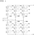
- FIG. 1 shows an example of a main circuit configuration of the power conversion device according to Embodiment 1.
- converters having circuit configurations in which converter cells are connected in series are generally called cascade converters, modular multilevel converters (MMCs), chain connection converters, or the like. Basically, the converters are series connection converters.
- a converter cell is defined as one including two or more semiconductor elements and one or more energy accumulating elements.
- FIG. 1 a plurality of cell converters 100 are connected in series between AC terminals U, V, and W and DC terminals P and N, and reactors 300P and 300N are provided therebetween.
- FIG. 1 is just an example, and the circuit configuration only has to be one in which converter cells are connected in series.
- the reactors 300P and 300N in each phase may be magnetically coupled to each other to form one reactor.
- the reactors may be concentrated on the negative electrode side (DC terminal N side).
- parasitic inductances such as wiring inductances may be provided instead of the reactors.
- FIG. 2 shows some of the cell converters 100 connected in series that are cut out from the power conversion device shown in FIG. 1 .
- FIG. 2 is a schematic circuit diagram showing a configuration of a cell converter 100.
- a circuit diagram of only a cell converter 100a is shown as a representative out of three cell converters 100a to 100c.
- the low-potential side of a switching element 1a and the high-potential side of a switching element 1b are connected in series to form a bridge.
- a capacitor 2 is connected to the high-potential side of the switching element 1a and the low-potential side of the switching element 1b, and accumulates and supplies DC energy according to an operation of the power conversion device.
- a positive terminal of the capacitor 2 and a high-potential terminal of the switching element 1a are connected to each other by a main circuit conductor 3a on the high-potential side.
- a negative terminal of the capacitor 2 and the low-potential side of the switching element 1b are connected to each other by a main circuit conductor 3b on the low-potential side.
- An external terminal X1 of the cell converter 100a is electrically connected to an external terminal X2 of the adjacent cell converter 100b by a conductor outside a housing or the like.
- An external terminal X2 of the cell converter 100a is electrically connected to an external terminal X1 of the adjacent cell converter 100c by a conductor outside the housing or the like.
- the cell converters 100a to 100c are in a state of being connected in series, and a multilevel converter which is the power conversion device shown in FIG. 1 is formed.
- a bypass portion 4 which is closed and enables a continuous operation of the power conversion device at the time of failure of the cell converter, is disposed between: a first external output conductor 5a connecting a connection point between the low-potential side of the switching element 1a and the high-potential side of the switching element 1b and the external terminal X1 on the high-potential side to each other; and a second external output conductor 5b connecting the low-potential side of the switching element 1b and the external terminal X2 on the low-potential side to each other.
- FIG. 3 is a diagram obtained by drawing a bypass current path in the circuit diagram in FIG. 2 . If an abnormality occurs in the cell converter 100a, the bypass portion 4 is closed. Specifically, if current flows in a downward direction from the cell converter 100b to the cell converter 100a and the cell converter 100c, current enters the cell converter 100a from the external terminal X1 of the cell converter 100a, passes through the bypass portion 4, is outputted from the external terminal X2, and flows to the cell converter 100c, as indicated by the thick line.
- FIG. 4 is a diagram obtained by drawing, in the circuit diagram in FIG. 2 , a bypass portion short-circuit current path inside the cell converter. If an abnormality is detected in the cell converter 100a, the bypass portion 4 is closed to form the current bypass path shown in FIG. 3 . At this time, the following case is assumed: double abnormalities have occurred in which the switching element 1b is not turned on in a state where the switching element 1a experiences a short-circuit failure. In this case, energy accumulated in the capacitor 2 becomes overcurrent, and the entire overcurrent flows on a circulation path indicated by the thick line in FIG. 4 into the bypass portion 4.
- bypass portion 4 If overcurrent flows into the bypass portion 4 in this manner so as to exceed the current resistance capacity thereof, the bypass portion 4 is damaged and cannot perform reliable opening and closing operations thereafter. Thus, a continuous operation of the power conversion device cannot be guaranteed.
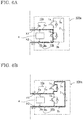
- FIG. 5 shows schematic diagrams of internal arrangement of the cell converter 100a.
- FIG. 5A is a front view
- FIG. 5B is a right side view.
- the constituents of the cell converter 100a are accommodated in a housing 200.
- the external terminals X1 and X2 are attached to the front surface of the housing 200.
- the first external output conductor 5a connected to the external terminal X1 extends in the depth direction of the housing 200 and is connected to the main circuit conductor 3a via a connection point (not shown) between the switching element 1a and the switching element 1b.
- the second external output conductor 5b connected to the external terminal X2 extends in the depth direction of the housing 200 and is connected to the main circuit conductor 3b.
- the first external output conductor 5a and the second external output conductor 5b are respectively at a high potential and a low potential, have opposite current directions, and are disposed so as to oppose each other in the vertical direction.
- the main circuit conductor 3a is connected to a high-potential-side terminal of the switching element 1a and a high-potential-side terminal (positive terminal) of the capacitor 2, and is at a high potential.
- the main circuit conductor 3b is connected to a low-potential-side terminal of the switching element 1b and a low-potential-side terminal (negative terminal) of the capacitor 2, and is at a low potential.
- the main circuit conductor 3a and the main circuit conductor 3b are disposed so as to oppose each other in the horizontal direction such that the directions of currents flowing in the switching element 1a and the switching element 1b are opposite directions.
- the first bypass connection conductor 6a has one end connected to a middle portion of the first external output conductor 5a and has another end connected to the high-potential side of the bypass portion 4.
- the second bypass connection conductor 6b has one end connected to a middle portion of the second external output conductor 5b and has another end connected to the low-potential side of the bypass portion 4.
- the first bypass connection conductor 6a and the second bypass connection conductor 6b have opposite current directions and are disposed so as to oppose each other in the horizontal direction.
- Mode 7 Current circulates through the capacitor 2, the main circuit conductor 3a, the switching element 1a, the first external output conductor 5a, the first bypass connection conductor 6a, the bypass portion 4, the second bypass connection conductor 6b, the second external output conductor 5b, the main circuit conductor 3b, and the capacitor 2 in this order.
- the first external output conductor 5a, of the first conductor portion 10a, between the main circuit conductor 3a and a connection with the first bypass connection conductor 6a and the second external output conductor 5b, of the second conductor portion 10b, between the main circuit conductor 3b and a connection with the second bypass connection conductor 6b are formed in bent shapes so as to have portions at which the direction of current flowing in the first external output conductor 5a and the direction of current flowing in the second external output conductor 5b are spatially the same direction in the case where the current path in FIG. 4 is formed in the above-described mode 7.
- the bent shapes include angled shapes obtained by bending in the shapes of polygonal lines and bowed shapes obtained by bending in the shapes of curves.
- FIG. 7 is a schematic diagram showing arrangement of the external output conductors according to the present embodiment in the cell converter.
- FIG. 7 is a perspective view from a frontward and diagonally upward direction in FIG. 5 . That is, FIG. 7 is a perspective view from the direction A indicated by the arrow in FIG. 5A and from the direction A indicated by the arrow in FIG. 5B .
- the first external output conductor 5a and the second external output conductor 5b are plate-shaped conductors each having a predetermined width and a predetermined thickness, are disposed so as to oppose each other in the vertical direction, and are each bent.
- the first external output conductor 5a has one end connected to the external terminal X1, has another end connected to the main circuit conductor 3a (not shown), and has a middle portion connected to the first bypass connection conductor 6a which is connected to the bypass portion 4 (not shown).
- the second external output conductor 5b is disposed so as to be separated downward from the first external output conductor 5a.
- the second external output conductor 5b has one end connected to the external terminal X2, has another end connected to the main circuit conductor 3b (not shown), and has a middle portion connected to the second bypass connection conductor 6b which is connected to the bypass portion 4 (not shown).
- the first bypass connection conductor 6a and the second bypass connection conductor 6b are disposed so as to have portions parallel to each other.
- FIGS. 8A to 8G explaining the following first external output conductor 5a and second external output conductor 5b according to Embodiment 1 are used as schematic plan views (top views) in which the first external output conductor 5a and the second external output conductor 5b in FIG. 7 are respectively developed in the directions of the arrows xa and xb in the x-direction.
- FIG. 8A shows schematic shapes of the external output conductors obtained by planarly developing the perspective view in FIG. 7 .
- the arrows 12a, 12b, and 12c each indicate a direction in which current flows, and each indicate a direction in the case where current flows from the high-potential side to the low-potential side of the bypass portion 4.
- connection locations with the main circuit conductors 3a and 3b are shown in a separated manner, and connection locations with the bypass connection conductors 6a and 6b are also shown in a separated manner.
- the first external output conductor 5a is made of an angled-shape conductor 7a
- the second external output conductor 5b is made of an angled-shape conductor 7b.
- the first external output conductor 5a has the one end connected to the external terminal X1, has the other end connected to the main circuit conductor 3a, and has the middle portion connected to one end of the first bypass connection conductor 6a.
- the second external output conductor 5b has the one end connected to the external terminal X2, has the other end connected to the main circuit conductor 3b, and has the middle portion connected to one end of the second bypass connection conductor 6b. Another end of the second bypass connection conductor 6b is connected to the low-potential side of the bypass portion 4.
- the first external output conductor 5a has a first portion 11a formed so as to extend along a second direction (x-direction) perpendicular to a first direction (y-direction, the depth direction of the housing 200) which is parallel to the arrow 12a and which is the direction of a path from the main circuit conductor 3a toward the external terminal X1.
- the second external output conductor 5b has a second portion 11b formed so as to extend along the second direction perpendicular to the first direction.
- the first portion 11a provided to the first external output conductor 5a is located so as to at least partially overlap with the second portion 11b of the second external output conductor 5b in a third direction (the z-direction in FIG. 7 ) perpendicular to both the first and second directions.
- the first portion 11a and the second portion 11b have the same current direction 12b and are disposed so as to adjacently oppose each other in the third direction (z-direction). Further, the first portion 11a is formed in a plate shape so as to have a first surface 13a, and the second portion 11b is formed in a plate shape so as to have a second surface 13b. The first surface 13a and the second surface 13b are each parallel to the third direction. The first portion 11a and the second portion 11b are disposed so as to be adjacent to each other in a direction parallel to the first surface 13a and the second surface 13b.
- first surface 13a and the second surface 13b are each parallel to the third direction in this manner, influence of electromagnetic repulsive force when short-circuit current flows to the bypass portion 4 can be alleviated at a portion at which the first external output conductor 5a is connected to the first bypass connection conductor 6a and a portion at which the second external output conductor 5b is connected to the second bypass connection conductor 6b. Accordingly, deformations of the first bypass connection conductor 6a, the second bypass connection conductor 6b, the first external output conductor 5a, and the second external output conductor 5b can be suppressed.
- FIG. 8B shows a configuration in which the bent shapes in FIG. 8A are formed by bowing plate-shaped conductors.
- the first external output conductor 5a is made of a bowed-shape conductor 8a
- the second external output conductor 5b is made of a bowed-shape conductor 8b.
- the first external output conductor 5a has the first portion 11a and the first surface 13a formed so as to extend along the second direction (x-direction)
- the second external output conductor 5b has the second portion 11b and the second surface 13b formed so as to extend along the second direction, and currents flow in spatially the same direction in the first surface 13a and the second surface 13b.
- operations are the same as those in FIG. 8A .
- FIG. 8A shows the external output conductors each formed in a bent shape by angling a single plate-shaped conductor
- the first and second external output conductors 5a and 5b are formed in the same angled shapes as those of the angled-shape conductors 7a and 7b in FIG. 8A by joining rectangular U-shaped conductors 9a, L-shaped conductors 9b, a rectangular S-shaped conductor 9c, and linear conductors 9e.
- the angled-shape conductors 7a and 7b in FIG. 8A are each formed of a single conductor and thus are difficult to be machined, the same shapes are obtained by combining a plurality of conductors that are easily machined. Apart from the shapes of the external output conductors, operations are the same as those in the aforementioned FIG. 8A .
- FIG. 8D is a modification of FIG. 8C .
- the first and second external output conductors 5a and 5b are formed in the same angled shapes as those of the angled-shape conductors 7a and 7b by joining L-shaped conductors 9b and rectangular S-shaped conductors 9c.
- the number of the types of shape conductors to be used can be reduced from four to two as compared to the configuration in the aforementioned FIG. 8C .
- operations are the same as those in the aforementioned FIG. 8A .
- FIG. 8E is a modification of FIG. 8D .
- rectangular S-shaped conductors 9c are replaced with rectangular U-shaped conductors 9a.
- a rectangular U-shaped conductor 9a for the first external output conductor 5a is attached so as to have a flat surface portion that is close to a lower side, i.e., the second external output conductor 5b, and a rectangular U-shaped conductor 9a for the second external output conductor 5b is attached so as to have a flat surface portion that is, in an opposing manner, close to an upper side, i.e., the first external output conductor 5a.
- operations are the same as those in the aforementioned FIG. 8A .
- FIG. 8B shows the external output conductors each formed in a bent shape by bowing a single plate-shaped conductor
- the first and second external output conductors 5a and 5b are formed in the same bowed shapes as those of the bowed-shape conductors 8a and 8b in FIG. 8B by joining U-shaped conductors 9d, L-shaped conductors 9b, a rectangular U-shaped conductor 9a, a rectangular S-shaped conductor 9c, and linear conductors 9e.
- the bowed-shape conductors 8a and 8b are each formed of a single conductor and thus are difficult to be machined, the same shapes are obtained by combining a plurality of conductors that are easily machined. Apart from the shapes of the external output conductors, operations are the same as those in the aforementioned FIG. 8A .
- FIG. 8G shows linear external output conductors.
- a first external output conductor 105a and a second external output conductor 105b are linear.
- the external output conductor 105a has one end connected to an external terminal X1, has another end connected to a main circuit conductor 103a, and has a middle portion connected to one end of a first bypass connection conductor 106a.
- Another end of the first bypass connection conductor 106a is connected to the high-potential side of a bypass portion 104.
- the second external output conductor 105b has one end connected to an external terminal X2, has another end connected to a main circuit conductor 103b, and has a middle portion connected to one end of a second bypass connection conductor 106b. Another end of the second bypass connection conductor 106b is connected to the low-potential side of the bypass portion 104.
- Current in the first external output conductor 105a and current in the second external output conductor 105b flow in opposite directions as indicated by the arrows, and the first external output conductor 105a and the second external output conductor 105b are disposed so as to face each other.
- the first external output conductor 105a and the second external output conductor 105b are linear, and the connection between the first bypass connection conductor 106a and the main circuit conductor 103a, and the connection between the second bypass connection conductor 106b and the main circuit conductor 103b, are shortest. Therefore, the self-inductance (Lc0) of the first external output conductor 105a and the self-inductance (Ld0) of the second external output conductor 105b are low.
- the first external output conductor 105a and the second external output conductor 105b are disposed so as to face each other, and currents in the external output conductors flow in different directions. Therefore, negative mutual inductances (-M) are generated.
- a combined inductance L0 is expressed with the following Expression (1).
- L 0 Lc 0 + Ld 0 ⁇ 2 M
- the first external output conductor 5a and the second external output conductor 5b are bent and thus have increased wiring lengths. Accordingly, the first external output conductor 5a and the second external output conductor 5b respectively have a higher self-inductance (Lc1: Lcl > Lc0) and a higher self-inductance (Ld1: Ld1 > Ld0) than the external output conductors having the shortest wiring lengths.
- current in the portion 11a of the first external output conductor 5a and current in the portion 11b of the second external output conductor 5b flow in spatially the same direction. Further, the portion 11a and the portion 11b are disposed so as to face each other along the current direction. Therefore, positive mutual inductances (+M) are generated.
- a combined inductance L1 is expressed with the following Expression (2).
- L1 Lc1 + Ld1 + 2 M
- the combined inductance becomes higher than that in the conventional configuration. Consequently, short-circuit current indicated by the thick line in FIG. 4 is suppressed before flowing to the bypass portion 4. Therefore, the bypass portion 4 can be inhibited from being damaged.
- the shapes of the external output conductors in FIG. 8B to FIG. 8F also allow the combined inductances to be higher than that in the conventional configuration in the same manner as in FIG. 8A , whereby the same advantageous effect can be exhibited. That is, since short-circuit current indicated by the thick line in FIG. 4 is suppressed before flowing to the bypass portion 4, the bypass portion 4 can be inhibited from being damaged.
- FIG. 8A to FIG. 8F the main circuit conductor 3a and the main circuit conductor 3b are shown so as to oppose each other. It is preferable that: the main circuit conductor 3a and the main circuit conductor 3b are disposed as shown in FIG. 8A to FIG. 8F ; and negative mutual inductances are generated between the main circuit conductor 3a and the main circuit conductor 3b so that low inductances are obtained.
- the main circuit conductor 3a and the main circuit conductor 3b having high inductances lead to application of high voltages to the switching elements 1a and 1b at the time of a normal operation, and thus are not preferable. Meanwhile, the main circuit conductors having low inductances lead to higher short-circuit current, but the configuration of the present embodiment enables suppression of the short-circuit current.
- FIG. 7 and FIG. 8A to FIG. 8F examples in which the second direction is perpendicular to the first direction have been shown. However, if the second direction intersects with the first direction, the second direction does not need to be perpendicular thereto. Current flowing in the second direction only has to have a component in a direction perpendicular to the first direction.
- the third term in the above-described Expression (2) takes a positive value, whereby short-circuit current is suppressed before flowing to the bypass portion 4.
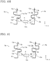
- FIG. 8H is a modification of FIG. 8A .
- FIG. 8A shows the direction of the arrow 12b as the second direction
- FIG. 8H is a diagram showing bent shapes formed such that the second direction is set to the direction of the arrow 12d in the first external output conductor 5a and is set to the direction of the arrow 12e in the second external output conductor 5b.
- Each of the arrows 12d and 12e is, for example, within an angle range not larger than 30° relative to the arrow 12b.
- an angle between the arrow 12d and the arrow 12e is, for example, not larger than 60°.
- the first portion 11a and the second portion 11b can exhibit the effect due to components in the same current direction 12b and can also exhibit the effect due to parallel components in the first surface 13a of the first portion 11a and the second surface 13b of the second portion 11b, i.e., the effect of alleviating influence of electromagnetic repulsive force when short-circuit current flows to the bypass portion 4.
- FIG. 8I is another modification of FIG. 8A .
- bent shapes are formed such that the second direction is set to the direction of the arrow 12d in both the first external output conductor 5a and the second external output conductor 5b.
- the arrow 12d is, for example, within an angle range not larger than 45° relative to the arrow 12b.
- the first portion 11a and the second portion 11b can exhibit the effect due to components in the same current direction 12b.
- the first surface 13a of the first portion 11a and the second surface 13b of the second portion 11b are parallel to each other, whereby it is also possible to exhibit the effect of alleviating influence of electromagnetic repulsive force when short-circuit current flows to the bypass portion 4.
- FIG. 8A Although two exemplary modifications of FIG. 8A have been shown, the same applies also to FIG. 8B to FIG. 8F . Specifically, if the second direction intersects with the first direction, the second direction does not need to be perpendicular thereto, and current flowing in the second direction only has to have a component in a direction perpendicular to the first direction.
- the second direction does not have to be perpendicular to the first direction and only has to be a direction intersecting with the first direction at an angle that is within the predetermined range; there only have to be components that are perpendicular to the first direction and that are in the same current direction; and, out of current components generated by forming the bent shapes, components in the same current direction are set to be higher than components in opposite current directions.
- a board and a power supply for driving the switching elements 1a and 1b and the bypass portion 4 are present in a space from the location at which the bypass portion 4 is disposed to the housing 200 for the cell converter located outward.
- Embodiment1 is such that: the shape of the first external output conductor 5a between the main circuit conductor 3a and the connection with the first bypass connection conductor 6a, and the shape of the second external output conductor 5b between the main circuit conductor 3b and the connection with the second bypass connection conductor 6b, are formed so as to include bent shapes; the first external output conductor 5a and the second external output conductor 5b have the first and second portions which extend in the direction perpendicular to the direction of each of the paths of the connections between the main circuit conductors 3a and 3b and the first and second bypass connection conductors 6a and 6b, i.e., the depth direction of the housing, respectively; these first and second portions at least spatially overlap with each other; and the directions of currents in the first and second portions are the same direction when double abnormalities occur in the cell converter.
- the inductances are increased, and thus overcurrent flowing to the bypass portion 4 can be suppressed, whereby a highly reliable power conversion device can be realized.
- the above-described external output conductors 5a and 5b having the bent shapes can be disposed by making use of the space in the housing.
- the first external output conductor 5a, of the first conductor portion 10a, between the main circuit conductor 3a and the connection with the first bypass connection conductor 6a and the second external output conductor 5b, of the second conductor portion 10b, between the main circuit conductor 3b and the connection with the second bypass connection conductor 6b, are formed in the above-described shapes so as to have portions at which the direction of current flowing in the first external output conductor 5a and the direction of current flowing in the second external output conductor 5b are spatially the same direction in the case where the current path in FIG. 4 is formed in the above-described mode 7.
- the first bypass connection conductor 6a of the first conductor portion 10a and the second bypass connection conductor 6b of the second conductor portion 10b are formed in bent shapes so as to have portions at which the direction of current flowing in the first bypass connection conductor 6a and the direction of current flowing in the second bypass connection conductor 6b are spatially the same direction.
- the bent shapes include angled shapes obtained by bending in the shapes of polygonal lines and bowed shapes obtained by bending in the shapes of curves.
- FIGS. 9A to 9G explaining the following first bypass connection conductor 6a and second bypass connection conductor 6b according to Embodiment2 are used as schematic plan views (right side views) in which: the first external output conductor 5a and the second external output conductor 5b in FIG. 7 are respectively replaced with the external output conductors in FIG. 8G ; and the first bypass connection conductor 6a and the second bypass connection conductor 6b shown so as to overlap with each other in the right side view in FIG. 5B are respectively developed in the directions of the arrows y1 and y2 in the y-direction in FIG. 7 .
- the first bypass connection conductor 6a is made of an angled-shape conductor 7a
- the second bypass connection conductor 6b is made of an angled-shape conductor 7b.
- the first bypass connection conductor 6a has one end connected to the first external output conductor 5a and has another end connected to the high-potential side of the bypass portion 4.
- the second bypass connection conductor 6b has one end connected to the second external output conductor 5b and has another end connected to the low-potential side of the bypass portion 4.
- the first bypass connection conductor 6a has a first portion 11a formed so as to extend along a second direction (the y-direction in FIG. 7 ) perpendicular to a first direction (the z-direction in FIG. 7 ) which is parallel to the arrow 12a and which is the direction of a path from the first external output conductor 5a toward the high-potential side of the bypass portion 4.
- the second bypass connection conductor 6b has a second portion 11b formed so as to extend along the second direction perpendicular to the first direction which is the direction of a path from the second external output conductor 5b toward the low-potential side of the bypass portion 4. Further, the first portion 11a of the first bypass connection conductor 6a is located so as to at least partially overlap with the second portion 11b of the second bypass connection conductor 6b in a third direction (the x-direction in FIG. 7 ) perpendicular to both the first and second directions.
- first portion 11a of the first bypass connection conductor 6a and the second portion 11b of the second bypass connection conductor 6b have the same current direction which is indicated by the arrow 12b and which is the second direction, and are disposed so as to adjacently oppose each other in the third direction.
- first portion 11a is formed in a plate shape so as to have a first surface 13a
- the second portion 11b is formed in a plate shape so as to have a second surface 13b.
- the first surface 13a and the second surface 13b are each parallel to the third direction.
- the first portion 11a and the second portion 11b are disposed so as to be adjacent to each other in a direction parallel to the first surface 13a and the second surface 13b.
- first surface 13a and the second surface 13b are each parallel to the third direction, influence of electromagnetic repulsive force when short-circuit current flows to the bypass portion 4 can be alleviated at portions at which the first bypass connection conductor 6a is connected to the bypass portion 4 and the first external output conductor 5a and portions at which the second bypass connection conductor 6b is connected to the bypass portion 4 and the second external output conductor 5b. Accordingly, deformations of the first bypass connection conductor 6a, the second bypass connection conductor 6b, the first external output conductor 5a, and the second external output conductor 5b can be suppressed.
- FIG. 9B shows a configuration in which the bent shapes in FIG. 9A are formed by bowing plate-shaped conductors.
- the first bypass connection conductor 6a is made of a bowed-shape conductor 8a
- the second bypass connection conductor 6b is made of a bowed-shape conductor 8b.
- the first bypass connection conductor 6a has the first portion 11a and the first surface 13a formed so as to extend along the second direction (y-direction)
- the second bypass connection conductor 6b has the second portion 11b and the second surface 13b formed so as to extend along the second direction
- currents flow in spatially the same direction in the first surface 13a and the second surface 13b.
- operations are the same as those in FIG. 9A .
- FIG. 9A shows the bypass connection conductors each formed in a bent shape by angling a single plate-shaped conductor
- FIG. 9C the first and second bypass connection conductors 6a and 6b are formed in the same angled shapes as those of the angled-shape conductors 7a and 7b in FIG. 9A by joining rectangular U-shaped conductors 9a, L-shaped conductors 9b, and linear conductors 9e.
- the angled-shape conductors 7a and 7b in FIG. 9A are each formed of a single conductor and thus are difficult to be machined, the same shapes are obtained by combining a plurality of conductors that are easily machined. Apart from the shapes of the bypass connection conductors, operations are the same as those in the aforementioned FIG. 9A .
- FIG. 9D is a modification of FIG. 9C .
- the first and second bypass connection conductors 6a and 6b are formed in the same angled shapes as those of the angled-shape conductors 7a and 7b by joining rectangular S-shaped conductors 9c.
- the number of the types of shape conductors to be used can be reduced from three to one as compared to the configuration in the aforementioned FIG. 9C .
- operations are the same as those in the aforementioned FIG. 9A .
- FIG. 9E is a modification of FIG. 9D .
- rectangular S-shaped conductors 9c are replaced with rectangular U-shaped conductors 9a.
- a rectangular U-shaped conductor 9a for the first bypass connection conductor 6a is attached so as to have a flat surface portion that is close to a left side, i.e., the second bypass connection conductor 6b, and a rectangular U-shaped conductor 9a for the second bypass connection conductor 6b is attached so as to have a flat surface portion that is, in an opposing manner, close to a right side, i.e., the first bypass connection conductor 6a.
- operations are the same as those in the aforementioned FIG. 9A .
- FIG. 9B shows the bypass connection conductors each formed in a bent shape by bowing a single plate-shaped conductor
- the first and second bypass connection conductors 6a and 6b are formed in the same bowed shapes as those of the bowed-shape conductors 8a and 8b in FIG. 9B by joining U-shaped conductors 9d, L-shaped conductors 9b, and linear conductors 9e.
- the bowed-shape conductors 8a and 8b in FIG. 9B are each formed of a single conductor and thus are difficult to be machined, the same shapes are obtained by combining a plurality of conductors that are easily machined. Apart from the shapes of the bypass connection conductors, operations are the same as those in the aforementioned FIG. 9A .
- FIG. 9G shows linear bypass connection conductors.
- a first bypass connection conductor 106a and a second bypass connection conductor 106b are linear.
- the first bypass connection conductor 106a has one end connected to the first external output conductor 105a and has another end connected to the high-potential side of the bypass portion 104.
- the second bypass connection conductor 106b has one end connected to the second external output conductor 105b and has another end connected to the low-potential side of the bypass portion 104.
- the first bypass connection conductor 106a and the second bypass connection conductor 106b are linear, and the connection between the bypass portion 104 and each of the first external output conductor 105a and the second external output conductor 105b is shortest. Therefore, the self-inductance (La0) of the first bypass connection conductor 106a and the self-inductance (Lb0) of the second bypass connection conductor 106b are low.
- the first bypass connection conductor 106a and the second bypass connection conductor 106b are disposed so as to face each other, and currents in the bypass connection conductors flow in different directions. Therefore, negative mutual inductances (-M) are generated.
- a combined inductance Lbp0 is expressed with the following Expression (3).
- Lbp 0 La 0 + Lb 0 ⁇ 2 M
- the first bypass connection conductor 6a and the second bypass connection conductor 6b have bent shapes and thus have increased wiring lengths. Accordingly, the first bypass connection conductor 6a and the second bypass connection conductor 6b respectively have a higher self-inductance (La1: Lal > La0) and a higher self-inductance (Lb1: Lb1 > Lb0) than the bypass connection conductors having the shortest wiring lengths.
- the combined inductance becomes higher than that in the conventional configuration. Consequently, short-circuit current indicated by the thick line in FIG. 4 is suppressed before flowing to the bypass portion 4. Therefore, the bypass portion 4 can be inhibited from being damaged.
- the shapes of the bypass connection conductors in FIG. 9B to FIG. 9F also allow the combined inductances to be higher than that in the conventional configuration in the same manner as in FIG. 9A , whereby the same advantageous effect can be exhibited. That is, since short-circuit current indicated by the thick line in FIG. 4 is suppressed before flowing to the bypass portion 4, the bypass portion 4 can be inhibited from being damaged.
- FIG. 9H is a modification of FIG. 9B . While FIG. 9B shows the arrows 12b as the second direction, FIG. 9H is a diagram showing bent shapes formed such that the second direction is set to the direction of the arrow 12d in the first bypass connection conductor 6a and is set to the direction of the arrow 12e in the second bypass connection conductor 6b.
- Each of the arrows 12d and 12e is, for example, within an angle range not larger than 30° relative to the arrow 12b.
- an angle between the arrow 12d and the arrow 12e is, for example, not larger than 60°.
- the first portion 11a and the second portion 11b can exhibit the effect due to components in the same current direction 12b and can also exhibit the effect due to parallel components in the first surface 13a of the first portion 11a and the second surface 13b of the second portion 11b, i.e., the effect of alleviating influence of electromagnetic repulsive force when short-circuit current flows to the bypass portion 4.
- FIG. 9I is another modification of FIG. 9B .
- bent shapes are formed such that the second direction is set to the direction of the arrow 12d in both the first bypass connection conductor 6a and the second bypass connection conductor 6b.
- the arrow 12d is, for example, within an angle range not larger than 45° relative to the arrow 12b.
- first portion 11a and the second portion 11b can exhibit the effect due to components in the same current direction 12b. Further, the first surface 13a of the first portion 11a and the second surface 13b of the second portion 11b are parallel to each other, whereby it is also possible to exhibit the effect of alleviating influence of electromagnetic repulsive force when short-circuit current flows to the bypass portion 4.
- FIG. 9B Although two exemplary modifications of FIG. 9B have been shown, the same applies also to FIG. 9A and FIG. 9C to FIG. 9F . Specifically, if the second direction intersects with the first direction, the second direction does not need to be perpendicular thereto, and current flowing in the second direction only has to have a component in a direction perpendicular to the first direction.
- Embodiment 2 is also such that: the second direction does not have to be perpendicular to the first direction and only has to be a direction intersecting with the first direction at an angle that is within the predetermined range; there only have to be components that are perpendicular to the first direction and that are in the same current direction; and, out of current components generated by forming the bent shapes, components in the same current direction are set to be higher than components in opposite current directions.
- a board and a power supply for driving the switching elements 1a and 1b and the bypass portion 4 are present in a space from the location at which the bypass portion 4 is disposed to the housing 200 for the cell converter located outward.
- Embodiment 2 is such that: the shape of the first bypass connection conductor 6a and the shape of the second bypass connection conductor 6b are formed so as to include bent shapes; the first bypass connection conductor 6a and the second bypass connection conductor 6b have the first and second portions which extend in the direction perpendicular to the direction from the connections with the first and second external output conductors 5a and 5b to the connections with the bypass portion 4, i.e., the up-down direction of the housing, respectively; these first and second portions at least spatially overlap with each other; and the directions of currents in the first and second portions are spatially the same direction when double abnormalities occur in the cell converter.
- bypass connection conductors 6a and 6b having the bent shapes can be disposed by making use of the space in the housing.
- Embodiments 11 and 2 may be combined with each other. In this case, care needs to be taken for arrangement so as not to increase the number of locations at which current directions are different between the adjacent conductors.
- plate-shaped conductors are used for the external output conductors 5a and 5b and the bypass connection conductors 6a and 6b have been described, the shapes of the conductors are not limited to plate shapes.
Landscapes
- Engineering & Computer Science (AREA)
- Power Engineering (AREA)
- Inverter Devices (AREA)
- Power Conversion In General (AREA)
Abstract
Description
- The present invention relates to a power conversion device in which a plurality of cell converters are connected in series.
- In power conversion devices for high-voltage application, multilevel converters have been put into practical use. A multilevel converter has been disclosed that has a circuit configuration in which: a plurality of cell converters are connected in series between AC terminals U, V, and W and DC terminals P and N; and AC voltage is generated at the AC terminals U, V, and W and DC voltage is generated at the DC terminals P and N, through ON/OFF control of semiconductor switching elements included in the converter cells.
- Meanwhile, there has been a power conversion device in which, when an abnormality occurs in a cell converter (submodule), output terminals of the cell converter (submodule) at which the abnormality has occurred are bypassed by a bypass portion (short-circuit device) so that a continuous operation can be performed (see, for example, Patent Document 1).
- A power conversion device in which a plurality of cell converters are connected in series to each other and which is applied to a high-voltage electric power line is such that, when an abnormality occurs in any of the cell converters, a bypass portion that performs closing for output terminals of the failing cell converter to exclude the failing cell converter from the series circuit guarantees a continuous operation of the power conversion device by means of this reliable closing operation. Thus, the bypass portion plays an important role in power management.
- However, there is a concern that such a bypass portion is put in a harsh state involving overcurrent or the like owing to the closing operation. If the bypass portion is damaged by being used in the harsh state, there is a case where the cell converter at which the abnormality has occurred cannot be reliably bypassed.
- Considering this, the applicant conceived a technology in which, when an abnormality in a cell converter is detected, a bypass portion is closed and, simultaneously with or prior to the closing of the bypass portion, a semiconductor element selected from among a plurality of semiconductor elements so as to continuously form, in parallel to the bypass portion, a current path that does not include the bypass portion is kept in an ON state during a period lasting until the closing of the bypass portion is established (see, for example, Patent Document 2).
-
- Patent Document 1:
Japanese Laid-Open Patent Publication (translation of PCT application) No. 2010-524426 FIG. 2 , etc.) - Patent Document 2: Japanese Patent
JP 5 889 498 B2 FIG. 7 , etc.) - In
Patent Document 2, when an abnormality in a cell converter is detected, a bypass portion is closed and, simultaneously with or prior to the closing of the bypass portion, a semiconductor element selected from among a plurality of semiconductor elements so as to continuously form, in parallel to the bypass portion, a current path that does not include the bypass portion is kept in an ON state during a period lasting until the closing of a bypass element is established. - However, technologies that deal with an abnormality in a semiconductor element selected so as to continuously form a current path that does not include such a bypass portion, have been required recently. That is, a continuous operation of a power conversion device has been required to be guaranteed also in the case where double abnormalities occur.
- The present invention has been made to solve the above-described problems, and an object of the present invention is to obtain a power conversion device in which, when double abnormalities in a cell converter occur, a bypass portion that performs closing for output terminals of the cell converter is prevented from being damaged owing to the closing operation so that a continuous operation can be performed.
- A power conversion device according to the present invention is a power conversion device in which a plurality of cell converters that perform power conversion are connected in series, each cell converter including:
a switching element; a capacitor; a main circuit conductor connecting the switching element and the capacitor to each other; two external terminals connected to other ones of the cell converters; a bypass portion disposed between the two external terminals and subjected to bypass connection; a first conductor portion connecting one of the two external terminals and each of the main circuit conductor and the bypass portion to each other; and a second conductor portion connecting another one of the two external terminals and each of the main circuit conductor and the bypass portion to each other. - The first and second conductor portions are each formed in a bent shape between the main circuit conductor and the bypass portion so as to, with respect to a first direction which is a direction of a path from the main circuit conductor to the bypass portion, have a portion that extends in a second direction intersecting with the first direction.
- A first portion, of the first conductor portion, that extends in the second direction and a second portion, of the second conductor portion, that extends in the second direction are disposed so as to at least partially overlap with each other in a third direction that intersects with the first and second directions. When current flows from the capacitor to the bypass portion, currents in a same direction flow in the first portion and the second portion.
- According to the power conversion device according to the present invention, overcurrent flowing to the bypass portion can be suppressed, whereby a highly reliable power conversion device can be realized. As a result, it is possible to obtain, without increasing the sizes of cell converters, a small-sized and inexpensive power conversion device that can be continuously operated also in the case where double abnormalities occur in any of the cell converters.
-
- FIG. 1
- is a schematic circuit diagram showing a configuration of a power conversion device according to
Embodiment 1. - FIG. 2
- is a schematic circuit diagram showing a configuration of a cell converter of the power conversion device according to
Embodiment 1. - FIG. 3
- is a schematic circuit diagram showing a bypass current path across a plurality of cell converters connected in series.
- FIG. 4
- is a schematic circuit diagram showing a bypass portion short-circuit current path inside the cell converter.
- FIG. 5
- shows schematic diagrams of an internal arrangement of the cell converter according to
Embodiment 1. - FIG. 6A
- is a schematic circuit diagram showing a path of current flowing in the cell converter in a steady state.
- FIG. 6B
- is a schematic circuit diagram showing another path of current flowing in the cell converter in the steady state.
- FIG. 6C
- is a schematic circuit diagram showing another path of current flowing in the cell converter in the steady state.
- FIG. 6D
- is a schematic circuit diagram showing another path of current flowing in the cell converter in the steady state.
- FIG. 7
- is a schematic perspective diagram showing arrangement of external output conductors according to
Embodiment 1 in the cell converter. - FIG. 8A
- shows schematic shapes of the external output conductors according to
Embodiment 1. - FIG. 8B
- shows other schematic shapes of the external output conductors according to
Embodiment 1. - FIG. 8C
- shows other schematic shapes of the external output conductors according to
Embodiment 1. - FIG. 8D
- shows other schematic shapes of the external output conductors according to
Embodiment 1. - FIG. 8E
- shows other schematic shapes of the external output conductors according to
Embodiment 1. - FIG. 8F
- shows other schematic shapes of the external output conductors according to
Embodiment 1. - FIG. 8G
- shows an example of external output conductors to be compared with the external output conductors according to
Embodiment 1. - FIG. 8H
- shows other schematic shapes of the external output conductors according to
Embodiment 1. - FIG. 81
- shows other schematic shapes of the external output conductors according to
Embodiment 1. - FIG. 9A
- shows schematic shapes of bypass connection conductors according to
Embodiment 2. - FIG. 9B
- shows other schematic shapes of the bypass connection conductors according to
Embodiment 2. - FIG. 9C
- shows other schematic shapes of the bypass connection conductors according to
Embodiment 2. - FIG. 9D
- shows other schematic shapes of the bypass connection conductors according to
Embodiment 2. - FIG. 9E
- shows other schematic shapes of the bypass connection conductors according to
Embodiment 2. - FIG. 9F
- shows other schematic shapes of the bypass connection conductors according to
Embodiment 2. - FIG. 9G
- shows an example of bypass connection conductors to be compared with the bypass connection conductors according to
Embodiment 2. - FIG. 9H
- shows other schematic shapes of the bypass connection conductors according to
Embodiment 2. - FIG. 9I
- shows other schematic shapes of the bypass connection conductors according to
Embodiment 2. - Hereinafter, the present embodiments will be described with reference to the drawings. In the drawings, the same or corresponding portions are denoted by the same reference characters.
- Hereinafter, a power conversion device according to
Embodiment 1 will be described with reference to the drawings. -
FIG. 1 shows an example of a main circuit configuration of the power conversion device according toEmbodiment 1. It is noted that converters having circuit configurations in which converter cells are connected in series are generally called cascade converters, modular multilevel converters (MMCs), chain connection converters, or the like. Basically, the converters are series connection converters. It is noted that, although described later, a converter cell is defined as one including two or more semiconductor elements and one or more energy accumulating elements. - In
FIG. 1 , a plurality ofcell converters 100 are connected in series between AC terminals U, V, and W and DC terminals P and N, andreactors FIG. 1 is just an example, and the circuit configuration only has to be one in which converter cells are connected in series. For example, thereactors -
FIG. 2 shows some of thecell converters 100 connected in series that are cut out from the power conversion device shown inFIG. 1 .FIG. 2 is a schematic circuit diagram showing a configuration of acell converter 100. Here, a circuit diagram of only acell converter 100a is shown as a representative out of threecell converters 100a to 100c. - In
FIG. 2 , the low-potential side of aswitching element 1a and the high-potential side of aswitching element 1b are connected in series to form a bridge. Acapacitor 2 is connected to the high-potential side of theswitching element 1a and the low-potential side of theswitching element 1b, and accumulates and supplies DC energy according to an operation of the power conversion device. - A positive terminal of the
capacitor 2 and a high-potential terminal of theswitching element 1a are connected to each other by amain circuit conductor 3a on the high-potential side. A negative terminal of thecapacitor 2 and the low-potential side of theswitching element 1b are connected to each other by amain circuit conductor 3b on the low-potential side. An external terminal X1 of thecell converter 100a is electrically connected to an external terminal X2 of theadjacent cell converter 100b by a conductor outside a housing or the like. - An external terminal X2 of the
cell converter 100a is electrically connected to an external terminal X1 of theadjacent cell converter 100c by a conductor outside the housing or the like. By these electrical connections, thecell converters 100a to 100c are in a state of being connected in series, and a multilevel converter which is the power conversion device shown inFIG. 1 is formed. - A
bypass portion 4 which is closed and enables a continuous operation of the power conversion device at the time of failure of the cell converter, is disposed between: a firstexternal output conductor 5a connecting a connection point between the low-potential side of theswitching element 1a and the high-potential side of theswitching element 1b and the external terminal X1 on the high-potential side to each other; and a secondexternal output conductor 5b connecting the low-potential side of theswitching element 1b and the external terminal X2 on the low-potential side to each other. - The first
external output conductor 5a and a firstbypass connection conductor 6a connecting the firstexternal output conductor 5a and the high-potential side of thebypass portion 4 to each other, form afirst conductor portion 10a. The secondexternal output conductor 5b and a secondbypass connection conductor 6b connecting the secondexternal output conductor 5b and the low-potential side of thebypass portion 4 to each other, form asecond conductor portion 10b. -
FIG. 3 is a diagram obtained by drawing a bypass current path in the circuit diagram inFIG. 2 . If an abnormality occurs in thecell converter 100a, thebypass portion 4 is closed. Specifically, if current flows in a downward direction from thecell converter 100b to thecell converter 100a and thecell converter 100c, current enters thecell converter 100a from the external terminal X1 of thecell converter 100a, passes through thebypass portion 4, is outputted from the external terminal X2, and flows to thecell converter 100c, as indicated by the thick line. - Meanwhile, if current flows in an upward direction from the
cell converter 100c to thecell converter 100a and thecell converter 100b, current enters thecell converter 100a from the external terminal X2 of thecell converter 100a, passes through thebypass portion 4, is outputted from the external terminal X1, and flows to thecell converter 100b, as indicated by the thick line. Thus, a continuous operation of the power conversion device can be performed. -
FIG. 4 is a diagram obtained by drawing, in the circuit diagram inFIG. 2 , a bypass portion short-circuit current path inside the cell converter. If an abnormality is detected in thecell converter 100a, thebypass portion 4 is closed to form the current bypass path shown inFIG. 3 . At this time, the following case is assumed: double abnormalities have occurred in which theswitching element 1b is not turned on in a state where the switchingelement 1a experiences a short-circuit failure. In this case, energy accumulated in thecapacitor 2 becomes overcurrent, and the entire overcurrent flows on a circulation path indicated by the thick line inFIG. 4 into thebypass portion 4. - Similarly, the following case is assumed: double abnormalities have occurred in which the
switching element 1a is turned on owing to erroneous operation simultaneously with detection of an abnormality in thecell converter 100a. In this case, since an operation logic is set such that the switchingelement 1b is not turned on when the switchingelement 1a is ON, energy accumulated in thecapacitor 2 becomes overcurrent, and the entire overcurrent flows on the circulation path indicated by the thick line into thebypass portion 4. - If overcurrent flows into the
bypass portion 4 in this manner so as to exceed the current resistance capacity thereof, thebypass portion 4 is damaged and cannot perform reliable opening and closing operations thereafter. Thus, a continuous operation of the power conversion device cannot be guaranteed. - Next, a structure of the cell converter according to
Embodiment 1 will be described.FIG. 5 shows schematic diagrams of internal arrangement of thecell converter 100a.FIG. 5A is a front view, andFIG. 5B is a right side view. InFIG. 5A and FIG. 5B , the constituents of thecell converter 100a are accommodated in ahousing 200. - The external terminals X1 and X2 are attached to the front surface of the
housing 200. The firstexternal output conductor 5a connected to the external terminal X1 extends in the depth direction of thehousing 200 and is connected to themain circuit conductor 3a via a connection point (not shown) between the switchingelement 1a and theswitching element 1b. - The second
external output conductor 5b connected to the external terminal X2 extends in the depth direction of thehousing 200 and is connected to themain circuit conductor 3b. The firstexternal output conductor 5a and the secondexternal output conductor 5b are respectively at a high potential and a low potential, have opposite current directions, and are disposed so as to oppose each other in the vertical direction. - The
main circuit conductor 3a is connected to a high-potential-side terminal of theswitching element 1a and a high-potential-side terminal (positive terminal) of thecapacitor 2, and is at a high potential. Themain circuit conductor 3b is connected to a low-potential-side terminal of theswitching element 1b and a low-potential-side terminal (negative terminal) of thecapacitor 2, and is at a low potential. Themain circuit conductor 3a and themain circuit conductor 3b are disposed so as to oppose each other in the horizontal direction such that the directions of currents flowing in theswitching element 1a and theswitching element 1b are opposite directions. - The first
bypass connection conductor 6a has one end connected to a middle portion of the firstexternal output conductor 5a and has another end connected to the high-potential side of thebypass portion 4. The secondbypass connection conductor 6b has one end connected to a middle portion of the secondexternal output conductor 5b and has another end connected to the low-potential side of thebypass portion 4. The firstbypass connection conductor 6a and the secondbypass connection conductor 6b have opposite current directions and are disposed so as to oppose each other in the horizontal direction. - Next, manners in which current flows inside the
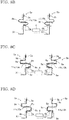
cell converter 100a in a steady state will be described with reference toFIGS. 6A to 6D . - 1) Mode 1: In the case where current is inputted from the external terminal X1 and the
switching element 1b is turned on. - As indicated by the solid line and the arrows in
FIG. 6A , current passes through the firstexternal output conductor 5a, the switchingelement 1b, and the secondexternal output conductor 5b in this order and is outputted from the external terminal X2. - 2) Mode 2: In the case where current is inputted from the external terminal X1 and the
switching element 1b is not turned on. - As indicated by the solid line and the arrows in
FIG. 6B , current passes through the firstexternal output conductor 5a, a diode portion of theswitching element 1a, themain circuit conductor 3a, thecapacitor 2, themain circuit conductor 3b, and the secondexternal output conductor 5b in this order and is outputted from the external terminal X2. - 3) Mode 3: In the case where current is inputted from the external terminal X2 and the
switching element 1a is turned on. - As indicated by the solid line and the arrows in
FIG. 6C , current passes through the secondexternal output conductor 5b, themain circuit conductor 3b, thecapacitor 2, themain circuit conductor 3a, the switchingelement 1a, and the firstexternal output conductor 5a in this order and is outputted from the external terminal X1. - 4) Mode 4: In the case where current is inputted from the external terminal X2 and the
switching element 1a is not turned on. - As indicated by the solid line and the arrows in
FIG. 6D , current passes through the secondexternal output conductor 5b, a diode portion of theswitching element 1b, and the firstexternal output conductor 5a in this order and is outputted from the external terminal X1. - In the case where an abnormality in the
cell converter 100a is detected and thebypass portion 4 is closed so that the current path inFIG. 3 is formed, current flows in the following two patterns. - 5) Mode 5: Current is inputted from the external terminal X1, passes through the first
external output conductor 5a, the firstbypass connection conductor 6a, thebypass portion 4, the secondbypass connection conductor 6b, and the secondexternal output conductor 5b in this order, and is outputted from the external terminal X2. - 6) Mode 6: Current is inputted from the external terminal X2, passes through the second
external output conductor 5b, the secondbypass connection conductor 6b, thebypass portion 4, the firstbypass connection conductor 6a, and the firstexternal output conductor 5a in this order, and is outputted from the external terminal X1 (the direction opposite to the current direction in mode 5). - In the case where an abnormality in the
cell converter 100a is detected and thebypass portion 4 is closed so that the current path inFIG. 4 is formed, current flows in the following pattern.
7) Mode 7: Current circulates through thecapacitor 2, themain circuit conductor 3a, the switchingelement 1a, the firstexternal output conductor 5a, the firstbypass connection conductor 6a, thebypass portion 4, the secondbypass connection conductor 6b, the secondexternal output conductor 5b, themain circuit conductor 3b, and thecapacitor 2 in this order. - In the present embodiment, the first
external output conductor 5a, of thefirst conductor portion 10a, between themain circuit conductor 3a and a connection with the firstbypass connection conductor 6a and the secondexternal output conductor 5b, of thesecond conductor portion 10b, between themain circuit conductor 3b and a connection with the secondbypass connection conductor 6b, are formed in bent shapes so as to have portions at which the direction of current flowing in the firstexternal output conductor 5a and the direction of current flowing in the secondexternal output conductor 5b are spatially the same direction in the case where the current path inFIG. 4 is formed in the above-described mode 7. Here, the bent shapes include angled shapes obtained by bending in the shapes of polygonal lines and bowed shapes obtained by bending in the shapes of curves. -
FIG. 7 is a schematic diagram showing arrangement of the external output conductors according to the present embodiment in the cell converter.FIG. 7 is a perspective view from a frontward and diagonally upward direction inFIG. 5 . That is,FIG. 7 is a perspective view from the direction A indicated by the arrow inFIG. 5A and from the direction A indicated by the arrow inFIG. 5B . - In
FIG. 7 , the firstexternal output conductor 5a and the secondexternal output conductor 5b are plate-shaped conductors each having a predetermined width and a predetermined thickness, are disposed so as to oppose each other in the vertical direction, and are each bent. The firstexternal output conductor 5a has one end connected to the external terminal X1, has another end connected to themain circuit conductor 3a (not shown), and has a middle portion connected to the firstbypass connection conductor 6a which is connected to the bypass portion 4 (not shown). - The second
external output conductor 5b is disposed so as to be separated downward from the firstexternal output conductor 5a. The secondexternal output conductor 5b has one end connected to the external terminal X2, has another end connected to themain circuit conductor 3b (not shown), and has a middle portion connected to the secondbypass connection conductor 6b which is connected to the bypass portion 4 (not shown). The firstbypass connection conductor 6a and the secondbypass connection conductor 6b are disposed so as to have portions parallel to each other. - Description will be given while
FIGS. 8A to 8G explaining the following firstexternal output conductor 5a and secondexternal output conductor 5b according toEmbodiment 1 are used as schematic plan views (top views) in which the firstexternal output conductor 5a and the secondexternal output conductor 5b inFIG. 7 are respectively developed in the directions of the arrows xa and xb in the x-direction. -
FIG. 8A shows schematic shapes of the external output conductors obtained by planarly developing the perspective view inFIG. 7 . InFIG. 8A , thearrows bypass portion 4. InFIG. 8A , connection locations with themain circuit conductors bypass connection conductors - In
FIG. 8A , the firstexternal output conductor 5a is made of an angled-shape conductor 7a, and the secondexternal output conductor 5b is made of an angled-shape conductor 7b. The firstexternal output conductor 5a has the one end connected to the external terminal X1, has the other end connected to themain circuit conductor 3a, and has the middle portion connected to one end of the firstbypass connection conductor 6a. - Another end of the first
bypass connection conductor 6a is connected to the high-potential side of thebypass portion 4. The secondexternal output conductor 5b has the one end connected to the external terminal X2, has the other end connected to themain circuit conductor 3b, and has the middle portion connected to one end of the secondbypass connection conductor 6b. Another end of the secondbypass connection conductor 6b is connected to the low-potential side of thebypass portion 4. - The first
external output conductor 5a has afirst portion 11a formed so as to extend along a second direction (x-direction) perpendicular to a first direction (y-direction, the depth direction of the housing 200) which is parallel to thearrow 12a and which is the direction of a path from themain circuit conductor 3a toward the external terminal X1. Similarly, the secondexternal output conductor 5b has asecond portion 11b formed so as to extend along the second direction perpendicular to the first direction. Further, thefirst portion 11a provided to the firstexternal output conductor 5a is located so as to at least partially overlap with thesecond portion 11b of the secondexternal output conductor 5b in a third direction (the z-direction inFIG. 7 ) perpendicular to both the first and second directions. - Returning to
FIG. 7 , thefirst portion 11a and thesecond portion 11b have the samecurrent direction 12b and are disposed so as to adjacently oppose each other in the third direction (z-direction). Further, thefirst portion 11a is formed in a plate shape so as to have afirst surface 13a, and thesecond portion 11b is formed in a plate shape so as to have asecond surface 13b. Thefirst surface 13a and thesecond surface 13b are each parallel to the third direction. Thefirst portion 11a and thesecond portion 11b are disposed so as to be adjacent to each other in a direction parallel to thefirst surface 13a and thesecond surface 13b. - If the
first surface 13a and thesecond surface 13b are each parallel to the third direction in this manner, influence of electromagnetic repulsive force when short-circuit current flows to thebypass portion 4 can be alleviated at a portion at which the firstexternal output conductor 5a is connected to the firstbypass connection conductor 6a and a portion at which the secondexternal output conductor 5b is connected to the secondbypass connection conductor 6b. Accordingly, deformations of the firstbypass connection conductor 6a, the secondbypass connection conductor 6b, the firstexternal output conductor 5a, and the secondexternal output conductor 5b can be suppressed. -
FIG. 8B shows a configuration in which the bent shapes inFIG. 8A are formed by bowing plate-shaped conductors. InFIG. 8B , the firstexternal output conductor 5a is made of a bowed-shape conductor 8a, and the secondexternal output conductor 5b is made of a bowed-shape conductor 8b. - In this structure as well, the first
external output conductor 5a has thefirst portion 11a and thefirst surface 13a formed so as to extend along the second direction (x-direction), the secondexternal output conductor 5b has thesecond portion 11b and thesecond surface 13b formed so as to extend along the second direction, and currents flow in spatially the same direction in thefirst surface 13a and thesecond surface 13b. Apart from the shapes of the first and second external output conductors, operations are the same as those inFIG. 8A . - Although
FIG. 8A shows the external output conductors each formed in a bent shape by angling a single plate-shaped conductor, inFIG. 8C , the first and secondexternal output conductors shape conductors FIG. 8A by joining rectangularU-shaped conductors 9a, L-shapedconductors 9b, a rectangular S-shapedconductor 9c, andlinear conductors 9e. - Although the angled-
shape conductors FIG. 8A are each formed of a single conductor and thus are difficult to be machined, the same shapes are obtained by combining a plurality of conductors that are easily machined. Apart from the shapes of the external output conductors, operations are the same as those in the aforementionedFIG. 8A . -
FIG. 8D is a modification ofFIG. 8C . InFIG. 8D , the first and secondexternal output conductors shape conductors conductors 9b and rectangular S-shapedconductors 9c. Thus, the number of the types of shape conductors to be used can be reduced from four to two as compared to the configuration in the aforementionedFIG. 8C . Apart from the shapes of the external output conductors, operations are the same as those in the aforementionedFIG. 8A . -
FIG. 8E is a modification ofFIG. 8D . InFIG. 8E , rectangular S-shapedconductors 9c are replaced with rectangularU-shaped conductors 9a. Out of these rectangularU-shaped conductors 9a, a rectangularU-shaped conductor 9a for the firstexternal output conductor 5a is attached so as to have a flat surface portion that is close to a lower side, i.e., the secondexternal output conductor 5b, and a rectangularU-shaped conductor 9a for the secondexternal output conductor 5b is attached so as to have a flat surface portion that is, in an opposing manner, close to an upper side, i.e., the firstexternal output conductor 5a. Apart from the shapes of the external output conductors, operations are the same as those in the aforementionedFIG. 8A . - Although
FIG. 8B shows the external output conductors each formed in a bent shape by bowing a single plate-shaped conductor, inFIG. 8F , the first and secondexternal output conductors shape conductors FIG. 8B by joiningU-shaped conductors 9d, L-shapedconductors 9b, a rectangularU-shaped conductor 9a, a rectangular S-shapedconductor 9c, andlinear conductors 9e. - Although the bowed-
shape conductors FIG. 8A . -
FIG. 8G shows linear external output conductors. A firstexternal output conductor 105a and a secondexternal output conductor 105b are linear. Theexternal output conductor 105a has one end connected to an external terminal X1, has another end connected to amain circuit conductor 103a, and has a middle portion connected to one end of a firstbypass connection conductor 106a. Another end of the firstbypass connection conductor 106a is connected to the high-potential side of abypass portion 104. - The second
external output conductor 105b has one end connected to an external terminal X2, has another end connected to amain circuit conductor 103b, and has a middle portion connected to one end of a secondbypass connection conductor 106b. Another end of the secondbypass connection conductor 106b is connected to the low-potential side of thebypass portion 104. Current in the firstexternal output conductor 105a and current in the secondexternal output conductor 105b flow in opposite directions as indicated by the arrows, and the firstexternal output conductor 105a and the secondexternal output conductor 105b are disposed so as to face each other. - Next, functions and effects of the shapes of the external output conductors according to the present embodiment shown in
FIG. 8A to FIG. 8F will be described through comparison withFIG. 8G . - First, in
FIG. 8G , the firstexternal output conductor 105a and the secondexternal output conductor 105b are linear, and the connection between the firstbypass connection conductor 106a and themain circuit conductor 103a, and the connection between the secondbypass connection conductor 106b and themain circuit conductor 103b, are shortest. Therefore, the self-inductance (Lc0) of the firstexternal output conductor 105a and the self-inductance (Ld0) of the secondexternal output conductor 105b are low. In addition, the firstexternal output conductor 105a and the secondexternal output conductor 105b are disposed so as to face each other, and currents in the external output conductors flow in different directions. Therefore, negative mutual inductances (-M) are generated. A combined inductance L0 is expressed with the following Expression (1).
- Meanwhile, in
FIG. 8A , the firstexternal output conductor 5a and the secondexternal output conductor 5b are bent and thus have increased wiring lengths. Accordingly, the firstexternal output conductor 5a and the secondexternal output conductor 5b respectively have a higher self-inductance (Lc1: Lcl > Lc0) and a higher self-inductance (Ld1: Ld1 > Ld0) than the external output conductors having the shortest wiring lengths. In addition, current in theportion 11a of the firstexternal output conductor 5a and current in theportion 11b of the secondexternal output conductor 5b flow in spatially the same direction. Further, theportion 11a and theportion 11b are disposed so as to face each other along the current direction. Therefore, positive mutual inductances (+M) are generated. A combined inductance L1 is expressed with the following Expression (2).
- It is found that L1 > L0 is satisfied.
- That is, the combined inductance becomes higher than that in the conventional configuration. Consequently, short-circuit current indicated by the thick line in
FIG. 4 is suppressed before flowing to thebypass portion 4. Therefore, thebypass portion 4 can be inhibited from being damaged. - The shapes of the external output conductors in
FIG. 8B to FIG. 8F also allow the combined inductances to be higher than that in the conventional configuration in the same manner as inFIG. 8A , whereby the same advantageous effect can be exhibited. That is, since short-circuit current indicated by the thick line inFIG. 4 is suppressed before flowing to thebypass portion 4, thebypass portion 4 can be inhibited from being damaged. - In
FIG. 8A to FIG. 8F , themain circuit conductor 3a and themain circuit conductor 3b are shown so as to oppose each other. It is preferable that: themain circuit conductor 3a and themain circuit conductor 3b are disposed as shown inFIG. 8A to FIG. 8F ; and negative mutual inductances are generated between themain circuit conductor 3a and themain circuit conductor 3b so that low inductances are obtained. - The
main circuit conductor 3a and themain circuit conductor 3b having high inductances lead to application of high voltages to theswitching elements - In
FIG. 7 and FIG. 8A toFIG. 8F , examples in which the second direction is perpendicular to the first direction have been shown. However, if the second direction intersects with the first direction, the second direction does not need to be perpendicular thereto. Current flowing in the second direction only has to have a component in a direction perpendicular to the first direction. - Further, in the case where currents flowing in the second direction are opposite to each other at some locations depending on the arrangement of the bent shapes, if components in the same current direction are set to be higher than components in opposite current directions, the third term in the above-described Expression (2) takes a positive value, whereby short-circuit current is suppressed before flowing to the
bypass portion 4. - For example,
FIG. 8H is a modification ofFIG. 8A . WhileFIG. 8A shows the direction of thearrow 12b as the second direction,FIG. 8H is a diagram showing bent shapes formed such that the second direction is set to the direction of thearrow 12d in the firstexternal output conductor 5a and is set to the direction of thearrow 12e in the secondexternal output conductor 5b. Each of thearrows arrow 12b. In addition, an angle between thearrow 12d and thearrow 12e is, for example, not larger than 60°. - In this case as well, the
first portion 11a and thesecond portion 11b can exhibit the effect due to components in the samecurrent direction 12b and can also exhibit the effect due to parallel components in thefirst surface 13a of thefirst portion 11a and thesecond surface 13b of thesecond portion 11b, i.e., the effect of alleviating influence of electromagnetic repulsive force when short-circuit current flows to thebypass portion 4. - Furthermore,
FIG. 8I is another modification ofFIG. 8A . In FIG. 81, bent shapes are formed such that the second direction is set to the direction of thearrow 12d in both the firstexternal output conductor 5a and the secondexternal output conductor 5b. Thearrow 12d is, for example, within an angle range not larger than 45° relative to thearrow 12b. In this case as well, thefirst portion 11a and thesecond portion 11b can exhibit the effect due to components in the samecurrent direction 12b. Further, thefirst surface 13a of thefirst portion 11a and thesecond surface 13b of thesecond portion 11b are parallel to each other, whereby it is also possible to exhibit the effect of alleviating influence of electromagnetic repulsive force when short-circuit current flows to thebypass portion 4. - Although two exemplary modifications of
FIG. 8A have been shown, the same applies also toFIG. 8B to FIG. 8F . Specifically, if the second direction intersects with the first direction, the second direction does not need to be perpendicular thereto, and current flowing in the second direction only has to have a component in a direction perpendicular to the first direction. - In this manner: the second direction does not have to be perpendicular to the first direction and only has to be a direction intersecting with the first direction at an angle that is within the predetermined range; there only have to be components that are perpendicular to the first direction and that are in the same current direction; and, out of current components generated by forming the bent shapes, components in the same current direction are set to be higher than components in opposite current directions.
- In addition, although not shown, a board and a power supply for driving the
switching elements bypass portion 4 are present in a space from the location at which thebypass portion 4 is disposed to thehousing 200 for the cell converter located outward. Thus, if a configuration is made in which positive mutual inductances (+M) are generated, there is no need for elongating, in order to increase the self-inductances, the lengths in the lateral direction of the external output conductors from the location at which thebypass portion 4 is disposed to a space located outward. Therefore, the external output conductors can be formed in reduced sizes. - As described above, Embodiment1 is such that: the shape of the first
external output conductor 5a between themain circuit conductor 3a and the connection with the firstbypass connection conductor 6a, and the shape of the secondexternal output conductor 5b between themain circuit conductor 3b and the connection with the secondbypass connection conductor 6b, are formed so as to include bent shapes; the firstexternal output conductor 5a and the secondexternal output conductor 5b have the first and second portions which extend in the direction perpendicular to the direction of each of the paths of the connections between themain circuit conductors bypass connection conductors - Consequently, the inductances are increased, and thus overcurrent flowing to the
bypass portion 4 can be suppressed, whereby a highly reliable power conversion device can be realized. Further, the above-describedexternal output conductors - In Embodiment1, the first
external output conductor 5a, of thefirst conductor portion 10a, between themain circuit conductor 3a and the connection with the firstbypass connection conductor 6a and the secondexternal output conductor 5b, of thesecond conductor portion 10b, between themain circuit conductor 3b and the connection with the secondbypass connection conductor 6b, are formed in the above-described shapes so as to have portions at which the direction of current flowing in the firstexternal output conductor 5a and the direction of current flowing in the secondexternal output conductor 5b are spatially the same direction in the case where the current path inFIG. 4 is formed in the above-described mode 7. - Meanwhile, in the present Embodiment2, the first
bypass connection conductor 6a of thefirst conductor portion 10a and the secondbypass connection conductor 6b of thesecond conductor portion 10b, are formed in bent shapes so as to have portions at which the direction of current flowing in the firstbypass connection conductor 6a and the direction of current flowing in the secondbypass connection conductor 6b are spatially the same direction. In the same manner as in Embodiment1, the bent shapes include angled shapes obtained by bending in the shapes of polygonal lines and bowed shapes obtained by bending in the shapes of curves. - Description will be given while
FIGS. 9A to 9G explaining the following firstbypass connection conductor 6a and secondbypass connection conductor 6b according to Embodiment2 are used as schematic plan views (right side views) in which: the firstexternal output conductor 5a and the secondexternal output conductor 5b inFIG. 7 are respectively replaced with the external output conductors inFIG. 8G ; and the firstbypass connection conductor 6a and the secondbypass connection conductor 6b shown so as to overlap with each other in the right side view inFIG. 5B are respectively developed in the directions of the arrows y1 and y2 in the y-direction inFIG. 7 . - In
FIG. 9A , the firstbypass connection conductor 6a is made of an angled-shape conductor 7a, and the secondbypass connection conductor 6b is made of an angled-shape conductor 7b. The firstbypass connection conductor 6a has one end connected to the firstexternal output conductor 5a and has another end connected to the high-potential side of thebypass portion 4. The secondbypass connection conductor 6b has one end connected to the secondexternal output conductor 5b and has another end connected to the low-potential side of thebypass portion 4. - The first
bypass connection conductor 6a has afirst portion 11a formed so as to extend along a second direction (the y-direction inFIG. 7 ) perpendicular to a first direction (the z-direction inFIG. 7 ) which is parallel to thearrow 12a and which is the direction of a path from the firstexternal output conductor 5a toward the high-potential side of thebypass portion 4. - Similarly, the second
bypass connection conductor 6b has asecond portion 11b formed so as to extend along the second direction perpendicular to the first direction which is the direction of a path from the secondexternal output conductor 5b toward the low-potential side of thebypass portion 4. Further, thefirst portion 11a of the firstbypass connection conductor 6a is located so as to at least partially overlap with thesecond portion 11b of the secondbypass connection conductor 6b in a third direction (the x-direction inFIG. 7 ) perpendicular to both the first and second directions. - That is, the
first portion 11a of the firstbypass connection conductor 6a and thesecond portion 11b of the secondbypass connection conductor 6b have the same current direction which is indicated by thearrow 12b and which is the second direction, and are disposed so as to adjacently oppose each other in the third direction. Further, thefirst portion 11a is formed in a plate shape so as to have afirst surface 13a, and thesecond portion 11b is formed in a plate shape so as to have asecond surface 13b. Thefirst surface 13a and thesecond surface 13b are each parallel to the third direction. Thefirst portion 11a and thesecond portion 11b are disposed so as to be adjacent to each other in a direction parallel to thefirst surface 13a and thesecond surface 13b. - If the
first surface 13a and thesecond surface 13b are each parallel to the third direction, influence of electromagnetic repulsive force when short-circuit current flows to thebypass portion 4 can be alleviated at portions at which the firstbypass connection conductor 6a is connected to thebypass portion 4 and the firstexternal output conductor 5a and portions at which the secondbypass connection conductor 6b is connected to thebypass portion 4 and the secondexternal output conductor 5b. Accordingly, deformations of the firstbypass connection conductor 6a, the secondbypass connection conductor 6b, the firstexternal output conductor 5a, and the secondexternal output conductor 5b can be suppressed. -
FIG. 9B shows a configuration in which the bent shapes inFIG. 9A are formed by bowing plate-shaped conductors. InFIG. 9B , the firstbypass connection conductor 6a is made of a bowed-shape conductor 8a, and the secondbypass connection conductor 6b is made of a bowed-shape conductor 8b. In this structure as well, the firstbypass connection conductor 6a has thefirst portion 11a and thefirst surface 13a formed so as to extend along the second direction (y-direction), the secondbypass connection conductor 6b has thesecond portion 11b and thesecond surface 13b formed so as to extend along the second direction, and currents flow in spatially the same direction in thefirst surface 13a and thesecond surface 13b. Apart from the shapes of the bypass connection conductors, operations are the same as those inFIG. 9A . - Although
FIG. 9A shows the bypass connection conductors each formed in a bent shape by angling a single plate-shaped conductor, inFIG. 9C , the first and secondbypass connection conductors shape conductors FIG. 9A by joining rectangularU-shaped conductors 9a, L-shapedconductors 9b, andlinear conductors 9e. - Although the angled-
shape conductors FIG. 9A are each formed of a single conductor and thus are difficult to be machined, the same shapes are obtained by combining a plurality of conductors that are easily machined. Apart from the shapes of the bypass connection conductors, operations are the same as those in the aforementionedFIG. 9A . -
FIG. 9D is a modification ofFIG. 9C . InFIG. 9D , the first and secondbypass connection conductors shape conductors conductors 9c. Thus, the number of the types of shape conductors to be used can be reduced from three to one as compared to the configuration in the aforementionedFIG. 9C . Apart from the shapes of the bypass connection conductors, operations are the same as those in the aforementionedFIG. 9A . -
FIG. 9E is a modification ofFIG. 9D . InFIG. 9E , rectangular S-shapedconductors 9c are replaced with rectangularU-shaped conductors 9a. Out of these rectangularU-shaped conductors 9a, a rectangularU-shaped conductor 9a for the firstbypass connection conductor 6a is attached so as to have a flat surface portion that is close to a left side, i.e., the secondbypass connection conductor 6b, and a rectangularU-shaped conductor 9a for the secondbypass connection conductor 6b is attached so as to have a flat surface portion that is, in an opposing manner, close to a right side, i.e., the firstbypass connection conductor 6a. Apart from the shapes of the bypass connection conductors, operations are the same as those in the aforementionedFIG. 9A . - Although
FIG. 9B shows the bypass connection conductors each formed in a bent shape by bowing a single plate-shaped conductor, inFIG. 9F , the first and secondbypass connection conductors shape conductors FIG. 9B by joiningU-shaped conductors 9d, L-shapedconductors 9b, andlinear conductors 9e. - Although the bowed-
shape conductors FIG. 9B are each formed of a single conductor and thus are difficult to be machined, the same shapes are obtained by combining a plurality of conductors that are easily machined. Apart from the shapes of the bypass connection conductors, operations are the same as those in the aforementionedFIG. 9A . -
FIG. 9G shows linear bypass connection conductors. A firstbypass connection conductor 106a and a secondbypass connection conductor 106b are linear. The firstbypass connection conductor 106a has one end connected to the firstexternal output conductor 105a and has another end connected to the high-potential side of thebypass portion 104. The secondbypass connection conductor 106b has one end connected to the secondexternal output conductor 105b and has another end connected to the low-potential side of thebypass portion 104. - Current in the first
bypass connection conductor 106a and current in the secondbypass connection conductor 106b flow in opposite directions as indicated by the arrows, and the firstbypass connection conductor 106a and the secondbypass connection conductor 106b are disposed so as to face each other. - Next, functions and effects of the shapes of the bypass connection conductors according to the present embodiment shown in
FIG. 9A to FIG. 9F will be described through comparison withFIG. 9G . - First, in
FIG. 9G , the firstbypass connection conductor 106a and the secondbypass connection conductor 106b are linear, and the connection between thebypass portion 104 and each of the firstexternal output conductor 105a and the secondexternal output conductor 105b is shortest. Therefore, the self-inductance (La0) of the firstbypass connection conductor 106a and the self-inductance (Lb0) of the secondbypass connection conductor 106b are low. In addition, the firstbypass connection conductor 106a and the secondbypass connection conductor 106b are disposed so as to face each other, and currents in the bypass connection conductors flow in different directions. Therefore, negative mutual inductances (-M) are generated. A combined inductance Lbp0 is expressed with the following Expression (3).
- Meanwhile, in
FIG. 9A , the firstbypass connection conductor 6a and the secondbypass connection conductor 6b have bent shapes and thus have increased wiring lengths. Accordingly, the firstbypass connection conductor 6a and the secondbypass connection conductor 6b respectively have a higher self-inductance (La1: Lal > La0) and a higher self-inductance (Lb1: Lb1 > Lb0) than the bypass connection conductors having the shortest wiring lengths. - In addition, current in the
first portion 11a of the firstbypass connection conductor 6a and current in thesecond portion 11b of the secondbypass connection conductor 6b flow in spatially the same direction. Further, thefirst portion 11a and thesecond portion 11b are disposed so as to face each other along the current direction. Therefore, positive mutual inductances (+M) are generated. A combined inductance Lbp1 is expressed with the following Expression (4).
- It is found that Lbp1 > Lbp0 is satisfied.
- That is, the combined inductance becomes higher than that in the conventional configuration. Consequently, short-circuit current indicated by the thick line in
FIG. 4 is suppressed before flowing to thebypass portion 4. Therefore, thebypass portion 4 can be inhibited from being damaged. - The shapes of the bypass connection conductors in
FIG. 9B to FIG. 9F also allow the combined inductances to be higher than that in the conventional configuration in the same manner as inFIG. 9A , whereby the same advantageous effect can be exhibited. That is, since short-circuit current indicated by the thick line inFIG. 4 is suppressed before flowing to thebypass portion 4, thebypass portion 4 can be inhibited from being damaged. - In
FIG. 9A to FIG. 9F , examples in which the second direction is perpendicular to the first direction have been shown. However, if the second direction intersects with the first direction, the second direction does not need to be perpendicular thereto. Current flowing in the second direction only has to have a component in a direction perpendicular to the first direction. Further, in the case where currents flowing in the second direction are opposite to each other at some locations depending on the arrangement of the bent shapes, if components in the same current direction are set to be higher than components in opposite current directions, the third term in the above-described Expression (4) takes a positive value, whereby short-circuit current is suppressed before flowing to thebypass portion 4. - For example,
FIG. 9H is a modification ofFIG. 9B . WhileFIG. 9B shows thearrows 12b as the second direction,FIG. 9H is a diagram showing bent shapes formed such that the second direction is set to the direction of thearrow 12d in the firstbypass connection conductor 6a and is set to the direction of thearrow 12e in the secondbypass connection conductor 6b. Each of thearrows arrow 12b. - In addition, an angle between the
arrow 12d and thearrow 12e is, for example, not larger than 60°. In this case as well, thefirst portion 11a and thesecond portion 11b can exhibit the effect due to components in the samecurrent direction 12b and can also exhibit the effect due to parallel components in thefirst surface 13a of thefirst portion 11a and thesecond surface 13b of thesecond portion 11b, i.e., the effect of alleviating influence of electromagnetic repulsive force when short-circuit current flows to thebypass portion 4. - Furthermore,
FIG. 9I is another modification ofFIG. 9B . InFIG. 9I , bent shapes are formed such that the second direction is set to the direction of thearrow 12d in both the firstbypass connection conductor 6a and the secondbypass connection conductor 6b. Thearrow 12d is, for example, within an angle range not larger than 45° relative to thearrow 12b. - In this case as well, the
first portion 11a and thesecond portion 11b can exhibit the effect due to components in the samecurrent direction 12b. Further, thefirst surface 13a of thefirst portion 11a and thesecond surface 13b of thesecond portion 11b are parallel to each other, whereby it is also possible to exhibit the effect of alleviating influence of electromagnetic repulsive force when short-circuit current flows to thebypass portion 4. - Although two exemplary modifications of
FIG. 9B have been shown, the same applies also toFIG. 9A and FIG. 9C toFIG. 9F . Specifically, if the second direction intersects with the first direction, the second direction does not need to be perpendicular thereto, and current flowing in the second direction only has to have a component in a direction perpendicular to the first direction. - In this manner,
Embodiment 2 is also such that: the second direction does not have to be perpendicular to the first direction and only has to be a direction intersecting with the first direction at an angle that is within the predetermined range; there only have to be components that are perpendicular to the first direction and that are in the same current direction; and, out of current components generated by forming the bent shapes, components in the same current direction are set to be higher than components in opposite current directions. - In addition, although not shown, a board and a power supply for driving the
switching elements bypass portion 4 are present in a space from the location at which thebypass portion 4 is disposed to thehousing 200 for the cell converter located outward. Thus, if a configuration is made in which positive mutual inductances (+M) are generated, there is no need for elongating, in order to increase the self-inductances, the lengths in the lateral direction of the bypass connection conductors from the location at which thebypass portion 4 is disposed to a space located outward. Therefore, the bypass connection conductors can be formed in reduced sizes. - As described above,
Embodiment 2 is such that: the shape of the firstbypass connection conductor 6a and the shape of the secondbypass connection conductor 6b are formed so as to include bent shapes; the firstbypass connection conductor 6a and the secondbypass connection conductor 6b have the first and second portions which extend in the direction perpendicular to the direction from the connections with the first and secondexternal output conductors bypass portion 4, i.e., the up-down direction of the housing, respectively; these first and second portions at least spatially overlap with each other; and the directions of currents in the first and second portions are spatially the same direction when double abnormalities occur in the cell converter. - Consequently, the inductances are increased, and thus overcurrent flowing to the
bypass portion 4 can be suppressed, whereby a highly reliable power conversion device can be realized. Further, the above-describedbypass connection conductors - In addition, since currents flow in the
external output conductors Embodiment 1 also inmode 1 tomode 4 which are steady operations so that power loss increases in association with increases in the inductances of theexternal output conductors Embodiment 2 in which the inductances of theexternal output conductors - It is noted that although the
external output conductors Embodiment 1 and thebypass connection conductors Embodiment 2, Embodiments 11 and 2 may be combined with each other. In this case, care needs to be taken for arrangement so as not to increase the number of locations at which current directions are different between the adjacent conductors. - In addition, although examples in which plate-shaped conductors are used for the
external output conductors bypass connection conductors - Although the invention is described above in terms of various exemplary embodiments and implementations, it should be understood that the various features, aspects, and functionality described in one or more of the individual embodiments are not limited in their applicability to the particular embodiment with which they are described, but instead can be applied, alone or in various combinations to one or more of the embodiments of the invention.
- It is therefore understood that numerous modifications which have not been exemplified can be devised without departing from the scope of the specification of the present invention. For example, at least one of the constituent parts may be modified, added, or eliminated. At least one of the constituent parts mentioned in at least one of the preferred embodiments may be selected and combined with the constituent parts mentioned in another preferred embodiment.
-
- 1a, 1b
- switching element
- 2
- capacitor
- 3a, 3b
- main circuit conductor
- 4
- bypass portion
- 5a
- first external output conductor
- 5b
- second external output conductor
- 6a
- first bypass connection conductor
- 6b
- second bypass connection conductor
- 7a, 7b
- angled-shape conductor
- 8a, 8b
- bowed-shape conductor
- 9a
- rectangular U-shaped conductor
- 9b
- L-shaped conductor
- 9c
- rectangular S-shaped conductor
- 9d
- U-shaped conductor
- 9e
- linear conductor
- 10a
- first conductor portion
- 10b
- second conductor portion
- 11a
- first portion
- 11b
- second portion
- 12a, 12b, 12c, 12d, 12e
- arrow
- 13a
- first surface
- 13b
- second surface
- X1, X2
- external terminal
- 100, 100a, 100b, 100c
- cell converter
Claims (10)
- A power conversion device in which a plurality of cell converters that perform power conversion are connected in series, each cell converter comprising:- a switching element;- a capacitor;- a main circuit conductor connecting the switching element and the capacitor to each other;- two external terminals connected to other ones of the cell converters;- a bypass portion disposed between the two external terminals and subjected to bypass connection;- a first conductor portion connecting one of the two external terminals and each of the main circuit conductor and the bypass portion to each other; and- a second conductor portion connecting another one of the two external terminals and each of the main circuit conductor and the bypass portion to each other, wherein- the first and second conductor portions are each formed in a bent shape between the main circuit conductor and the bypass portion so as to, with respect to a first direction which is a direction of a path from the main circuit conductor to the bypass portion, have a portion that extends in a second direction intersecting with the first direction,- a first portion, of the first conductor portion, that extends in the second direction and a second portion, of the second conductor portion, that extends in the second direction are disposed so as to at least partially overlap with each other in a third direction that intersects with the first and second directions, and- when current flows from the capacitor to the bypass portion, currents in a same direction flow in the first portion and the second portion.
- The power conversion device according to claim 1,wherein the first conductor portion includes- a first external output conductor connecting the one of the two external terminals and the main circuit conductor to each other, and- a first bypass connection conductor connecting the first external output conductor and one end of the bypass portion to each other,wherein the second conductor portion includes- a second external output conductor connecting the other one of the two external terminals and the main circuit conductor to each other, and- a second bypass connection conductor connecting the second external output conductor and another end of the bypass portion to each other,- the first portion is provided to the first bypass connection conductor, and- the second portion is provided to the second bypass connection conductor.
- The power conversion device according to claim 2,wherein the first portion is formed by angling a part of the first bypass connection conductor which is a single conductor member, andthe second portion is formed by angling a part of the second bypass connection conductor which is a single conductor member.
- The power conversion device according to claim 2,wherein the first portion is formed by bowing a part of the first bypass connection conductor which is a single conductor member, andthe second portion is formed by bowing a part of the second bypass connection conductor which is a single conductor member.
- The power conversion device according to claim 2,
wherein each of the first and second bypass connection conductors is formed by combining conductors from among an L-shaped conductor, an S-shaped conductor, a U-shaped conductor, and a linear conductor. - The power conversion device according to claim 1,wherein the first conductor portion includes- a first external output conductor connecting the one of the two external terminals and the main circuit conductor to each other, and- a first bypass connection conductor connecting the first external output conductor and one end of the bypass portion to each other,wherein the second conductor portion includes- a second external output conductor connecting the other one of the two external terminals and the main circuit conductor to each other, and- a second bypass connection conductor connecting the second external output conductor and another end of the bypass portion to each other,- the first portion is provided to the first external output conductor, and- the second portion is provided to the second external output conductor.
- The power conversion device according to claim 6,wherein the first external output conductor is composed of a single conductor member between the main circuit conductor and a connection with the first bypass connection conductor,the first portion is formed by angling a part of the first bypass connection conductor which is a single conductor member,the second external output conductor is composed of a single conductor member between the main circuit conductor and a connection with the second bypass connection conductor, andthe second portion is formed by angling a part of the second bypass connection conductor which is a single conductor member.
- The power conversion device according to claim 6,wherein the first external output conductor is composed of a single conductor member between the main circuit conductor and a connection with the first bypass connection conductor,the first portion is formed by bowing a part of the first bypass connection conductor which is a single conductor member,the second external output conductor is composed of a single conductor member between the main circuit conductor and a connection with the second bypass connection conductor, andthe second portion is formed by bowing a part of the second bypass connection conductor which is a single conductor member.
- The power conversion device according to claim 6,
wherein each of the first and second external output conductors is formed by combining conductors from among an L-shaped conductor, an S-shaped conductor, a U-shaped conductor, and a linear conductor. - The power conversion device according to any one of claims 1 to 9,wherein the first portion has a first surface which is parallel to the third direction, andthe second portion has a second surface which is parallel to the third direction.
Applications Claiming Priority (1)
| Application Number | Priority Date | Filing Date | Title |
|---|---|---|---|
| PCT/JP2019/007996 WO2020178877A1 (en) | 2019-03-01 | 2019-03-01 | Power conversion device |
Publications (2)
| Publication Number | Publication Date |
|---|---|
| EP3934091A1 true EP3934091A1 (en) | 2022-01-05 |
| EP3934091A4 EP3934091A4 (en) | 2022-03-02 |
Family
ID=67692138
Family Applications (1)
| Application Number | Title | Priority Date | Filing Date |
|---|---|---|---|
| EP19918119.9A Pending EP3934091A4 (en) | 2019-03-01 | 2019-03-01 | POWER CONVERSION DEVICE |
Country Status (4)
| Country | Link |
|---|---|
| US (1) | US11699959B2 (en) |
| EP (1) | EP3934091A4 (en) |
| JP (1) | JP6563163B1 (en) |
| WO (1) | WO2020178877A1 (en) |
Families Citing this family (1)
| Publication number | Priority date | Publication date | Assignee | Title |
|---|---|---|---|---|
| KR102784027B1 (en) * | 2021-06-08 | 2025-03-21 | 한국전력공사 | Multilevel converter with bypass protection element for each submodule group |
Family Cites Families (11)
| Publication number | Priority date | Publication date | Assignee | Title |
|---|---|---|---|---|
| JP3424532B2 (en) * | 1997-11-25 | 2003-07-07 | 株式会社日立製作所 | Power converter |
| WO2008028435A1 (en) * | 2006-09-06 | 2008-03-13 | Siemens Aktiengesellschaft | Short-circuit current meter |
| DE102007018344B4 (en) | 2007-04-16 | 2022-08-04 | Siemens Energy Global GmbH & Co. KG | Device for protecting converter modules |
| DE102011004733A1 (en) * | 2011-02-25 | 2012-08-30 | Siemens Aktiengesellschaft | Submodule of a modular multistage converter |
| US20160036314A1 (en) * | 2013-03-18 | 2016-02-04 | Mitsubishi Electric Corporation | Power conversion apparatus |
| WO2015133365A1 (en) * | 2014-03-05 | 2015-09-11 | 三菱電機株式会社 | Power conversion device |
| JP6416411B2 (en) * | 2015-11-04 | 2018-10-31 | 三菱電機株式会社 | Power converter |
| US10468972B2 (en) * | 2016-05-25 | 2019-11-05 | Mitsubishi Electric Corporation | Power converter including a plurality of converter cells connected in multiple series |
| JP6351878B1 (en) * | 2016-09-02 | 2018-07-04 | 三菱電機株式会社 | Busbar structure and power converter using the same |
| JP6643972B2 (en) * | 2016-12-13 | 2020-02-12 | 日立オートモティブシステムズ株式会社 | Bus bar structure and power conversion device using the same |
| WO2018193606A1 (en) * | 2017-04-21 | 2018-10-25 | 東芝三菱電機産業システム株式会社 | Power conversion device |
-
2019
- 2019-03-01 US US17/417,774 patent/US11699959B2/en active Active
- 2019-03-01 WO PCT/JP2019/007996 patent/WO2020178877A1/en not_active Ceased
- 2019-03-01 EP EP19918119.9A patent/EP3934091A4/en active Pending
- 2019-03-01 JP JP2019527269A patent/JP6563163B1/en active Active
Also Published As
| Publication number | Publication date |
|---|---|
| JPWO2020178877A1 (en) | 2021-03-18 |
| JP6563163B1 (en) | 2019-08-21 |
| WO2020178877A1 (en) | 2020-09-10 |
| EP3934091A4 (en) | 2022-03-02 |
| US11699959B2 (en) | 2023-07-11 |
| US20210391807A1 (en) | 2021-12-16 |
Similar Documents
| Publication | Publication Date | Title |
|---|---|---|
| US9538680B2 (en) | Laminated busbar for power converter and the converter thereof | |
| US10374521B2 (en) | Busbar arrangement | |
| US8902612B2 (en) | Power conversion apparatus | |
| EP3667893B1 (en) | Power conversion device | |
| JP5132175B2 (en) | Power converter | |
| EP3136580B1 (en) | Power conversion unit and power conversion device | |
| CN105580503A (en) | Power conversion unit, power conversion apparatus, and power conversion apparatus manufacturing method | |
| JP2011010496A (en) | Electronic power converter | |
| KR101373170B1 (en) | Converter | |
| US12136884B2 (en) | Power converter | |
| CN113994559B (en) | Laminated busbar, power converter, power conversion device, and uninterruptible power supply device | |
| JP4609075B2 (en) | Power converter wiring structure | |
| EP3934091A1 (en) | Power conversion device | |
| US11973413B2 (en) | Power conversion device | |
| CN100517949C (en) | power conversion device | |
| EP3550712B1 (en) | Power conversion device | |
| EP3562023B1 (en) | Power conversion device | |
| JP4842018B2 (en) | Power converter | |
| JP6796392B2 (en) | 3-level power converter | |
| JP5894321B1 (en) | Power conversion unit and power conversion device | |
| KR102603062B1 (en) | Input terminal of power module of double-side cooling | |
| JP6786943B2 (en) | Capacitor device | |
| JP2001359284A (en) | Power converter | |
| JP2020054146A (en) | Inverter |
Legal Events
| Date | Code | Title | Description |
|---|---|---|---|
| STAA | Information on the status of an ep patent application or granted ep patent |
Free format text: STATUS: THE INTERNATIONAL PUBLICATION HAS BEEN MADE |
|
| PUAI | Public reference made under article 153(3) epc to a published international application that has entered the european phase |
Free format text: ORIGINAL CODE: 0009012 |
|
| STAA | Information on the status of an ep patent application or granted ep patent |
Free format text: STATUS: REQUEST FOR EXAMINATION WAS MADE |
|
| 17P | Request for examination filed |
Effective date: 20210819 |
|
| AK | Designated contracting states |
Kind code of ref document: A1 Designated state(s): AL AT BE BG CH CY CZ DE DK EE ES FI FR GB GR HR HU IE IS IT LI LT LU LV MC MK MT NL NO PL PT RO RS SE SI SK SM TR |
|
| A4 | Supplementary search report drawn up and despatched |
Effective date: 20220128 |
|
| RIC1 | Information provided on ipc code assigned before grant |
Ipc: H02M 7/00 20060101ALI20220125BHEP Ipc: H02M 7/483 20070101ALI20220125BHEP Ipc: H02M 1/32 20070101ALI20220125BHEP Ipc: H02M 7/48 20070101ALI20220125BHEP Ipc: H02M 7/49 20070101AFI20220125BHEP |
|
| DAV | Request for validation of the european patent (deleted) | ||
| DAX | Request for extension of the european patent (deleted) | ||
| STAA | Information on the status of an ep patent application or granted ep patent |
Free format text: STATUS: EXAMINATION IS IN PROGRESS |
|
| 17Q | First examination report despatched |
Effective date: 20230324 |