EP3933237B1 - Ventilkartusche für ein elektronisches mischventil mit erweitertem bewegungsbereich, mischventil damit und methode zur verwendung des mischventils - Google Patents
Ventilkartusche für ein elektronisches mischventil mit erweitertem bewegungsbereich, mischventil damit und methode zur verwendung des mischventils Download PDFInfo
- Publication number
- EP3933237B1 EP3933237B1 EP20716099.5A EP20716099A EP3933237B1 EP 3933237 B1 EP3933237 B1 EP 3933237B1 EP 20716099 A EP20716099 A EP 20716099A EP 3933237 B1 EP3933237 B1 EP 3933237B1
- Authority
- EP
- European Patent Office
- Prior art keywords
- range
- motion
- extended
- handle
- cartridge
- Prior art date
- Legal status (The legal status is an assumption and is not a legal conclusion. Google has not performed a legal analysis and makes no representation as to the accuracy of the status listed.)
- Active
Links
Images

Classifications
-
- F—MECHANICAL ENGINEERING; LIGHTING; HEATING; WEAPONS; BLASTING
- F16—ENGINEERING ELEMENTS AND UNITS; GENERAL MEASURES FOR PRODUCING AND MAINTAINING EFFECTIVE FUNCTIONING OF MACHINES OR INSTALLATIONS; THERMAL INSULATION IN GENERAL
- F16K—VALVES; TAPS; COCKS; ACTUATING-FLOATS; DEVICES FOR VENTING OR AERATING
- F16K11/00—Multiple-way valves, e.g. mixing valves; Pipe fittings incorporating such valves
- F16K11/02—Multiple-way valves, e.g. mixing valves; Pipe fittings incorporating such valves with all movable sealing faces moving as one unit
- F16K11/06—Multiple-way valves, e.g. mixing valves; Pipe fittings incorporating such valves with all movable sealing faces moving as one unit comprising only sliding valves, i.e. sliding closure elements
- F16K11/078—Multiple-way valves, e.g. mixing valves; Pipe fittings incorporating such valves with all movable sealing faces moving as one unit comprising only sliding valves, i.e. sliding closure elements with pivoted and linearly movable closure members
- F16K11/0782—Single-lever operated mixing valves with closure members having flat sealing faces
-
- E—FIXED CONSTRUCTIONS
- E03—WATER SUPPLY; SEWERAGE
- E03C—DOMESTIC PLUMBING INSTALLATIONS FOR FRESH WATER OR WASTE WATER; SINKS
- E03C1/00—Domestic plumbing installations for fresh water or waste water; Sinks
- E03C1/02—Plumbing installations for fresh water
- E03C1/04—Water-basin installations specially adapted to wash-basins or baths
- E03C1/0412—Constructional or functional features of the faucet handle
-
- F—MECHANICAL ENGINEERING; LIGHTING; HEATING; WEAPONS; BLASTING
- F16—ENGINEERING ELEMENTS AND UNITS; GENERAL MEASURES FOR PRODUCING AND MAINTAINING EFFECTIVE FUNCTIONING OF MACHINES OR INSTALLATIONS; THERMAL INSULATION IN GENERAL
- F16K—VALVES; TAPS; COCKS; ACTUATING-FLOATS; DEVICES FOR VENTING OR AERATING
- F16K31/00—Actuating devices; Operating means; Releasing devices
- F16K31/02—Actuating devices; Operating means; Releasing devices electric; magnetic
-
- E—FIXED CONSTRUCTIONS
- E03—WATER SUPPLY; SEWERAGE
- E03C—DOMESTIC PLUMBING INSTALLATIONS FOR FRESH WATER OR WASTE WATER; SINKS
- E03C1/00—Domestic plumbing installations for fresh water or waste water; Sinks
- E03C1/02—Plumbing installations for fresh water
- E03C1/05—Arrangements of devices on wash-basins, baths, sinks, or the like for remote control of taps
- E03C1/055—Electrical control devices, e.g. with push buttons, control panels or the like
- E03C1/057—Electrical control devices, e.g. with push buttons, control panels or the like touchless, i.e. using sensors
-
- F—MECHANICAL ENGINEERING; LIGHTING; HEATING; WEAPONS; BLASTING
- F16—ENGINEERING ELEMENTS AND UNITS; GENERAL MEASURES FOR PRODUCING AND MAINTAINING EFFECTIVE FUNCTIONING OF MACHINES OR INSTALLATIONS; THERMAL INSULATION IN GENERAL
- F16K—VALVES; TAPS; COCKS; ACTUATING-FLOATS; DEVICES FOR VENTING OR AERATING
- F16K19/00—Arrangements of valves and flow lines specially adapted for mixing fluids
- F16K19/006—Specially adapted for faucets
-
- F—MECHANICAL ENGINEERING; LIGHTING; HEATING; WEAPONS; BLASTING
- F16—ENGINEERING ELEMENTS AND UNITS; GENERAL MEASURES FOR PRODUCING AND MAINTAINING EFFECTIVE FUNCTIONING OF MACHINES OR INSTALLATIONS; THERMAL INSULATION IN GENERAL
- F16K—VALVES; TAPS; COCKS; ACTUATING-FLOATS; DEVICES FOR VENTING OR AERATING
- F16K31/00—Actuating devices; Operating means; Releasing devices
- F16K31/44—Mechanical actuating means
- F16K31/52—Mechanical actuating means with crank, eccentric, or cam
- F16K31/524—Mechanical actuating means with crank, eccentric, or cam with a cam
- F16K31/52475—Mechanical actuating means with crank, eccentric, or cam with a cam comprising a sliding valve
- F16K31/52483—Mechanical actuating means with crank, eccentric, or cam with a cam comprising a sliding valve comprising a multiple-way sliding valve
-
- F—MECHANICAL ENGINEERING; LIGHTING; HEATING; WEAPONS; BLASTING
- F16—ENGINEERING ELEMENTS AND UNITS; GENERAL MEASURES FOR PRODUCING AND MAINTAINING EFFECTIVE FUNCTIONING OF MACHINES OR INSTALLATIONS; THERMAL INSULATION IN GENERAL
- F16K—VALVES; TAPS; COCKS; ACTUATING-FLOATS; DEVICES FOR VENTING OR AERATING
- F16K31/00—Actuating devices; Operating means; Releasing devices
- F16K31/44—Mechanical actuating means
- F16K31/60—Handles
- F16K31/605—Handles for single handle mixing valves
-
- F—MECHANICAL ENGINEERING; LIGHTING; HEATING; WEAPONS; BLASTING
- F16—ENGINEERING ELEMENTS AND UNITS; GENERAL MEASURES FOR PRODUCING AND MAINTAINING EFFECTIVE FUNCTIONING OF MACHINES OR INSTALLATIONS; THERMAL INSULATION IN GENERAL
- F16K—VALVES; TAPS; COCKS; ACTUATING-FLOATS; DEVICES FOR VENTING OR AERATING
- F16K37/00—Special means in or on valves or other cut-off apparatus for indicating or recording operation thereof, or for enabling an alarm to be given
- F16K37/0025—Electrical or magnetic means
- F16K37/0041—Electrical or magnetic means for measuring valve parameters
-
- G—PHYSICS
- G05—CONTROLLING; REGULATING
- G05D—SYSTEMS FOR CONTROLLING OR REGULATING NON-ELECTRIC VARIABLES
- G05D23/00—Control of temperature
- G05D23/19—Control of temperature characterised by the use of electric means
- G05D23/1919—Control of temperature characterised by the use of electric means characterised by the type of controller
-
- G—PHYSICS
- G05—CONTROLLING; REGULATING
- G05D—SYSTEMS FOR CONTROLLING OR REGULATING NON-ELECTRIC VARIABLES
- G05D23/00—Control of temperature
- G05D23/19—Control of temperature characterised by the use of electric means
- G05D23/1925—Control of temperature characterised by the use of electric means using a combination of auxiliary electric and non-electric power
Definitions
- the present invention relates to a cartridge for an electronic tap with an extended operative range of motion that allows moving the handle or lever of the tap in which it is installed beyond its normal operation range determined by a first stop.
- the invention also relates to the tap including said cartridge with a handle having an extended operative range of motion and to the operation method thereof.
- the prior art for taps actuated manually by a handle or lever includes numerous taps that transfer said actuation of the handle or lever to an inner mechanical cartridge that performs the mixing ratio of the fluids and controls the flow.
- a system is used for detecting the position of the handle or lever in order to transmit the control parameters associated with said detected position to the electronic systems for controlling the fluid mixture and flow.
- taps with a mechanical operation cartridge having manually actuated handles which, in addition to having conventional ranges of motion in the rotation and inclination axes, have an extended operative range that allows moving the handle beyond the conventional end of said range by overcoming a resistance to passing said end of the range.
- this first stop is determined by a normally elastic piece which reaches the end of the range of motion, such that the two stops rely on this same piece.
- Patent US2015/299991 A1 discloses an element according to the preamble of claim 1.
- the aim of the present invention is to provide a cartridge for an electronic tap with an extended operative range of motion to perform additional functions.
- a further aim of the invention is the electronic tap including same and the operation method thereof, which allows configuring a novel and advantageous product with the advantages over the prior art described below.
- the present invention provides a cartridge for an electronic tap with an extended operative range of motion, to which is coupled a handle or lever with a rotational and tilting motion for manually regulating the outlet parameters of the flow in the tap in which the cartridge is installed, and wherein the cartridge receives the movement of said handle or controller through a cam that moves together with the handle or controller.
- This cartridge is having at least:
- the end of range of motion stops are provided by the geometry of the cartridge components being different from that of those providing the passage stop function, by said geometries entering in contact such that movement in said direction is prevented.
- the end of range stop can be established by geometries of the cartridge component that establish the same passable stop, by contact between said geometries, preventing further motion in said direction.
- the set of end of range stops for the various ends of the motion of the handle or controller is provided by geometries of the cartridge components that establish the same passable stop and/or by geometries of the cartridge components different from those establishing the passable stop function, by contact between these geometries, preventing further motion in said direction.
- the passable stops in the tilting range of motion of the cam correspond to a terminal connected to a compression spring, with a preload such that the force required is greater than that for moving the cam in the normal tilting range of motion in order to overcome the resistance to motion provided by said spring and accessing the extended operative range of motion.
- the tilting end of range of motion stop is established by the contact between the moving disc of the cartridge that displaces the cam with a point in the cartridge that is static with respect to the motion in the tilting plane of the cam.
- the passable stops in the range of motion of the cam are the two terminals connected to either a spring plate or a preloaded coil spring, where each terminal is embedded or arranged in a part integrally joined to the rotation of the cam such that in its rotation, when one of said terminals contacts a stop geometry at a static part of the cartridge, a force greater than that for moving the cam in the normal rotational range of motion is required to overcome the resistance to continuing said motion provided by said spring and begin said extended range of motion, while the rotational end of range stop is established by contact between a geometry in the form of a protrusion of the piece joined to the cam rotation and a geometry of the static walls of the cartridge that is interposed preventing continuing the motion of said protrusion.
- the tap has extended ranges of motion in the two rotational directions of motion of the cam and the two tilting directions of motion of the cam.
- This embodiment of the invention with extended ranges of motion in both ends of both possible motions allows providing the tap with multiple additional functionalities at each end of the ranges of motion when the first stop is passed and the extended range of motion is entered, such that the user can enjoy several possible actuations of said functionalities in each extended range of motion used.
- the cartridge has means for detecting the position of the cam consisting in at least a triaxial magnetic sensor placed in a static disc of the cartridge and a magnetic field generating element that moves together with the cam.
- This option incorporates a system for detecting the position of the handle, both in the positions corresponding to the conventional ranges of motion and in the positions of the handle in the extended ranges of motion, and uses the detection of the magnetic field intensity in the three Cartesian axes to determine both the angular orientation of the magnetic field generating element and therefore the rotation angle of the handle, and the position along the tilting range of motion.
- the triaxial magnetic sensor is placed on a static base of the cartridge with one of the three detection Cartesian axes essentially coaxial or parallel to the axis of rotation of the handle or controller of the cartridge; and where the position of the magnetic field generating element when the handle or lever in its tilting range of motion is approximately at the middle of its range is placed essentially centred on said axis of rotation of the handle or lever of the cartridge, and therefore also essentially centred on the corresponding Cartesian axis of detection essentially coaxial or parallel to said axis of rotation of the handle or lever of the cartridge.
- the alternative described above allows obtaining a symmetrical pattern in the magnetic field intensity measured in the movements corresponding to the tilting and rotation ranges of motion of the magnetic field generating element with respect to the central position of inclination of the handle or lever and the position of triaxial magnetic sensor, improving the use of the available range of measurement of the sensors, advantageously symmetrical for positive and negative intensities, improving the resolution and accuracy of measurement throughout the entire range of positions, particularly in the extreme positions corresponding to the positions of the handle in the extended ranges, and simplifying subsequent calculations to relate the measurements of the triaxial magnetic sensor with the tilting and rotational positions of the handle or lever in said positions.
- the processing means in the extended range of motion areas near the passable stop, defined as safety areas do not determine a new parametrisation of the fluid and do not execute an auxiliary specific function.
- the present invention provides an electronic tap containing a tap cartridge with an extended operative range of motion as that indicated in the preceding features of the present description.
- Said tap is characterised in that the handle or controller of the tap that is joined to the cartridge cam has extended operative ranges in the possible axes of motion of the handle or controller, and electronic detection means for the position of said handle or controller, where the tap is provided with operative positions that correspond to:
- the electronic tap is also characterised in that between the various detection areas of the conventional and extended range positions, there are safety areas where there is no assigned parametrisation of the fluid nor an auxiliary function.
- the electronic tap through the control system thereof, establishes a measurement area of the position in the transition between the passable stop and the end of range stop, in the extended range segment, where the configuration of the fluid mixture and fluid flow is unchanged and the existing functions are neither activated nor disabled, as a safety measure against accidental actuations by the user, tolerances and hysteresis of the kinematic chain and the resolution of the electronics.
- the present invention provides an operation method for an electronic tap as indicated above containing a tap cartridge with an extended operative range as that also indicated in the present description.
- the method is characterised in that the electronic control system of the tap that receives the measurement of the detection means carries out at least the following steps:
- the auxiliary functions are performed by entering the extended range areas with an actuation pulse, without having to maintain pressure on the handle, or by keeping the handle in said area while the function is applied, where a different auxiliary function can be assigned to each type of actuation performed on the handle.
- each of the extended range areas is further divided into various subareas according to the entry point determined by the position of the handle or controller in each different degree of liberty in which the extended area is entered, to provide the tap with additional functionalities according to whether the position is in one extended range subarea or another.
- auxiliary functions executed by the tap control system or the execution commands sent to associated external elements are at least one or more of those described below, or combinations thereof:
- the method of operation includes the sending, by the processing means, of acknowledgement, reply and information signals to the user regarding both the execution of the auxiliary functions associated with the extended ranges, and the regulation selected in the execution of the usual positions of the handle or controller using display means of the tap itself and/or external to it with luminous, alphanumerical and/or audible signals.
- This provides users with a visual and/or acoustic confirmation of the parametrisation set by them while operating the handle in both conventional ranges and in the extended ranges in which additional functions are assigned such as those described above.
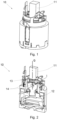
- a cartridge (10) is installed in an electronic sanitary water mixing tap (100) that is provided with a handle (101) with which the user regulates the mixing ratio of hot and cold water and the supply flow.
- the handle (101) is connected to a cam (11) to which the movement thereof is transmitted and that performs the rotation and tilting movements, with the same axis of rotation (G) as the handle (101) in the rotation motion thereof, and the same axis of rotation (I) as the handle (101) in the tilting motion thereof.
- the cam (11) is integrally joined to a moving disc (12) or the like that acts as a kinematic chain joined to the motion of the handle (101), executing the motion on a plane defined between the walls of the cartridge (10).
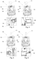
- the cam (11) is provided with an elastic element, in this case a preloaded compression spring (13) with stops (14) at the ends thereof, said spring (13) being placed on the plane of of the tilting motion, such that the stops (14) contact static retention geometries of the bushing (15) of the cartridge (10), with respect to the elevation motion of the cam (11) in the conventional flow regulation positions, between the maximum flow aperture, figure 3 , and the closing of the flow, figure 5 . In these positions and in the intermediate positions the spring (13) does not exert any force on the retention geometries of the bushing (15).
- the handle (101) can continue its tilting motion along the direction in which said contact with the retention geometries of the bushing (15) has been reached, overcoming the force exerted by the spring (13) against advancing in this direction, increasing the compression of the spring (13) and therefore its potential energy.
- This tilting motion that is transformed in the present invention into a translational motion of the mobile disc (12) ends at the extended range when the mobile disc (12) contacts a physical end of range stop, such as a static wall (26) of the bushing (15) of the cartridge (10) with respect to the lifting motion of the cam (11).
- a physical end of range stop such as a static wall (26) of the bushing (15) of the cartridge (10) with respect to the lifting motion of the cam (11).
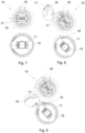
- the cam (11) has an elastic element, in this case a preloaded spring plate (16), with stops (17) at its ends, said spring plate (16) being located at the outer perimeter of the rotational motion of the bushing (15) where the cam (11) is joined to the mobile disc (12) in said rotational motion, such that the stops (17) are in the bushing (15), contacting static retention geometries (18) of the cartridge (10) at the conventional hot and cold water mixing regulation positions that are at the ends of the maximum temperature regulation, figure 8 , and the minimum temperature regulation, not shown as it is analogous in the opposite direction. At these end positions and at the intermediate positions the spring plate (16) does not exert any force on the retention pieces (18).
- the handle (101) can continue its rotation motion along the direction in which said contact with the retention geometries of the bushing (18) have been reached, overcoming the force exerted by the spring plate (16) against advancing in this direction, increasing the bending of the spring plate (16) and therefore its potential energy.
- the end of range stops for the rotation and the tilting motion can act on the same part that establishes the passable stop.
- Passable stops and end of range stops for the displacement can be disposed in the same cartridge (10) in different pieces, in the same piece, or both solutions may be disposed in one or another end of extended range stop for the same tap.
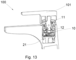
- the cartridge has control means embodied, as shown in figures 12 and 13 , by a triaxial magnetic sensor (20) with processing means for the measurements taken by said sensor of the magnetic field intensity generated by a magnet (21) fitted in the mobile disc (12) and which therefore moves together with said mobile disc (12).
- Determining the position of the magnet with each regulation movement made by the user on the handle requires regulation parameters for the hot and cold mixing ratio and the overall supply flow. These positions and the associated regulation are transmitted to the means in charge of electronically regulating said water mixing and flow.
- the triaxial magnetic sensor (20) is housed in a static base (22) of the cartridge (10) with one (Z) of the three detection Cartesian axes (X, Y, Z) essentially coaxial or parallel to the axis of rotation (G) of the handle (101) of the cartridge (10), wherein the position of the magnet (21) when the handle (101) in its tilting range of motion is approximately at the middle of the range is essentially centred on said axis of rotation (G) of the handle (101) of the cartridge (10), and therefore also essentially centred on the corresponding Cartesian axis (Z) of detection essentially coaxial or parallel to said axis of rotation (G) of the handle (101) of the cartridge (10).
- the processing means in the extended range areas near the passable stop, defined as safety areas, do not determine a new parametrisation of the fluid nor do they execute a specific auxiliary function, preventing an accidental execution of the additional functionalities assigned in said extended ranges.
- the electronic tap (100) that contains the cartridge (10) has extended operative ranges (31, 32, 33, 34, 35, 36, 37 and 38) in each of the ends of the tilting and rotation motions of the handle (101) as well as the combined extreme positions of the tilting and rotation positions at the same time.
- the method of operation of the electronic tap (100) with the cartridge (10) with extended operative ranges is programmed and governed by the electronic control system of the tap (100) that receives the measurement from the triaxial magnetic sensor (20), and performs the following steps:
- the auxiliary functions are performed by the entry in the extended range areas (31, 32, 33, 34, 35, 36, 37 or 38) by a pulse or maintaining (t) the handle (101) in said area during the application of the function, optionally assigning a different auxiliary function for each type of actuation performed on the handle (101).
- Entry in each of the extended range areas can be associated with a different functionality if said are in turn divided into different subareas in the control system that detects the point of entry in the extended range, in order to provide the tap (100) with various functionalities depending on the position in one or another subarea of the extended range.
- auxiliary functions programmed in and governed by the control system of the tap (100) by sending execution commands to associated external elements can be, among others:
- the exit from said adjacent area due to the actuation of the handle (101) by the user, moving it in the area (39) before the special function ends may be used to stop said special function and dispense the mix and flow as in the normal behaviour in the conventional range area (39).
- the method of operation sends acknowledgement, reply and information signals through the processing means to the user regarding the execution of the auxiliary functions associated with the extended ranges, and with the regulation selected in the execution of the usual positions of the handle (101), by means of display means of the tap (100) itself and/or external to same, not shown in the figures, with luminous, alphanumerical and/or acoustic signals, providing the user with a visual and/or acoustic confirmation of the parametrisation selected when operating the handle (101) in both the conventional ranges and the extended ranges in which additional functions such as those described above are assigned.
Landscapes
- Engineering & Computer Science (AREA)
- General Engineering & Computer Science (AREA)
- Mechanical Engineering (AREA)
- Health & Medical Sciences (AREA)
- Life Sciences & Earth Sciences (AREA)
- Hydrology & Water Resources (AREA)
- Public Health (AREA)
- Water Supply & Treatment (AREA)
- Physics & Mathematics (AREA)
- General Physics & Mathematics (AREA)
- Automation & Control Theory (AREA)
- Power Engineering (AREA)
- Multiple-Way Valves (AREA)
- Preventing Unauthorised Actuation Of Valves (AREA)
- Domestic Plumbing Installations (AREA)
- Mechanical Control Devices (AREA)
Claims (15)
- Kartusche für einen elektronischen Wasserhahn mit einem erweiterten Bedienungsbewegungsbereich, an dem ein Griff oder Hebel mit einer Dreh- und Kippbewegung zur manuellen Regulierung der Ausgabeparameter der Strömung in dem Wasserhahn, in dem die Kartusche installiert ist, gekoppelt ist, wobei die Kartusche die Bewegung des Griffs oder der Steuerung durch einen Nocken erhält, der sich zusammen mit dem Griff oder der Steuerung bewegt, wobei die Kartusche wenigstens umfasst:- einen Kippbewegungsbereich für den Nocken (11), der mit dem Griff (101) oder der Steuerung verbunden ist, der wenigstens an einem der Enden des Kippbereichs des Nockens (11) mit einem ersten passierbaren Anschlag (14) versehen ist, der durch ein Element gebildet ist, das an einem ersten Punkt in dem Pfad einen Widerstand gegenüber einem Fortsetzen in der Verlagerungsrichtung darstellt, und der nach Aufbringen einer größeren Kraft als bei der üblichen Verlagerung des Nockens (11), die zum Überwinden des Widerstands ausreicht, das Bewegen des Nockens (11) in der Richtung längs eines Segments eines erweiterten Pfadbereichs bis zu einem nicht passierbaren Ende des Pfadbereichs (26) fortsetzt, und wobei die Kraft, die durch den Widerstand ausgeübt wird, um den ersten passierbaren Anschlag (14) zu überwinden, bei der Verlagerung in dem erweiterten Pfadbereich anhält und ausreichend ist, um den Nocken (11) zu dem ersten Punkt in dem Kippbewegungsbereich zurückkehren zu lassen, wenn der Benutzer das Einwirken auf den Griff oder die Steuerung (101) beendet, wobei die Kartusche dadurch gekennzeichnet ist, dass sie ferner umfasst:- einen Drehbewegungsbereich für den Nocken (11), der mit dem Griff oder der Steuerung (101) verbunden ist, der wenigstens an einem der Enden des Drehbereichs des Nockens (11) mit einem zweiten passierbaren Anschlag (17) versehen ist, der durch ein Element gebildet wird, das an einem ersten Punkt in dem Pfad einen Widerstand gegenüber einem Fortsetzen in der Verlagerungsrichtung bietet, und der nach Aufbringen einer größeren Kraft als bei der üblichen Verlagerung des Nockens (11), die zum Überwinden des Widerstands ausreicht, die Bewegung des Nockens (11) in der Richtung längs eines Segments eines erweiterten Bereichs bis zu einem nicht passierbaren Ende des Bereichs (19) fortsetzt, und wobei die Kraft, die durch den Widerstand ausgeübt wird, um den zweiten passierbaren Anschlag (17) zu überwinden, bei der Verlagerung in dem erweiterten Bereich anhält und ausreichend ist, um den Nocken (11) zu dem ersten Punkt in dem Drehbewegungsbereich zurückkehren zu lassen, wenn der Benutzer das Einwirken auf den Griff oder die Steuerung (101) beendet,- ein elektronisches Steuerungssystem, das versehen ist mit wenigstens einigen Mitteln (20) zum Detektieren der Position des Griffs oder der Steuerung (101) an den verschiedenen Punkten in dem Bewegungsbereich jeder der Verlagerungsachsen (X, Y, Z) davon, einer Kipp- und einer Drehbewegung, und das außerdem wenigstens einige Verarbeitungsmittel aufweist, die die Informationen über die Position des Nockens (11) erhalten und auf die Mittel zum Regulieren der Mischung und der Strömung des Fluids einwirken, sowie mit zusätzlichen Funktionen an den Positionen, die sich innerhalb der erweiterten Bereiche befinden.
- Kartusche für einen elektronischen Wasserhahn mit einem erweiterten Bedienungsbewegungsbereich nach Anspruch 1, wobei der Bereichsendanschlag (26, 19) durch Geometrien von Komponenten der Kartusche (10), die andere als diejenigen sind, die die Funktion des passierbaren Anschlags (14, 17) ausführen, durch Kontakt zwischen den Geometrien gebildet wird, um zu verhindern, dass Bewegung in dieser Richtung fortgesetzt wird.
- Kartusche für einen elektronischen Wasserhahn mit einem erweiterten Bedienungsbewegungsbereich nach einem der vorhergehenden Ansprüche, wobei der Satz von Bereichsendanschlägen (26, 19) für die verschiedenen Enden der Bewegung des Griffs (101) oder der Steuerung durch Geometrien der Komponenten der Kartusche (10), die denselben passierbaren Anschlag (14, 17) bilden, und/oder durch Geometrien der Kartuschenkomponenten (10), die sich von jenen unterscheiden, die die Funktion des passierbaren Anschlags (14, 17) bilden, durch Kontakt zwischen diesen Geometrien gebildet wird, um weitere Bewegung in dieser Richtung zu verhindern.
- Kartusche für einen elektronischen Wasserhahn mit einem erweiterten Bedienungsbewegungsbereich nach Anspruch 1, wobei die passierbaren Anschläge (14) in dem Kippbewegungsbereich des Nockens (11) Endpunkte sind, die mit einer Kompressionsfeder (13) mit einer Vorspannung verbunden sind, so dass es erforderlich ist, eine Kraft auszuüben, die größer als die zum Bewegen des Nockens (11) in dem normalen Kippbewegungsbereich ist, um den Widerstand für die Bewegung zu überwinden, der durch die Feder (13) verursacht wird, und in den erweiterten Bewegungsbereich vorzudringen, wobei der Bereichsendanschlag (26) der Kippbewegung durch den Kontakt zwischen der beweglichen Platte (12) der Kartusche (10), die den Nocken (11) bewegt, mit einem Punkt der Kartusche (10), der in Bezug auf die Bewegung in der Bewegungsebene der beweglichen Platte (12) statisch ist, gebildet wird.
- Kartusche für einen elektronischen Wasserhahn mit einem erweiterten Bedienungsbewegungsbereich nach Anspruch 1, wobei die passierbaren Anschläge (17) in dem Drehbewegungsbereich des Nockens (11) zwei Endpunkte (17) sind, die entweder mit einer Federplatte (16) oder einer vorgespannten Spiralfeder verbunden sind, wobei jeder Endpunkt (17) in ein Teil eingebettet ist, das mit der Drehung des Nockens (11) integral verbunden ist, so dass es bei dessen Drehung, wenn einer der Endpunkte (17) eine Anschlaggeometrie (18) bei einem statischen Teil der Kartusche (10) kontaktiert, eine Kraft erforderlich ist, die größer als die Kraft ist, die zum Bewegen des Nockens (11) in dem normalen Drehbewegungsbereich erforderlich ist, um den Widerstand zu überwinden, um die Bewegung fortzusetzen, der durch die Feder (16) bereitgestellt wird, und den erweiterten Bewegungsbereich zu beginnen, wobei der Drehbereichsendanschlag (19) durch einen Kontakt zwischen einer Geometrie in der Form eines Vorsprungs des Teils, das mit der Drehung des Nockens (11) verbunden ist, und einer Geometrie der statischen Wände (19) der Kartusche, die dazwischen angeordnet ist, gebildet wird, um eine Fortsetzung der Bewegung des Vorsprungs zu verhindern.
- Kartusche für einen elektronischen Wasserhahn mit einem erweiterten Bedienungsbewegungsbereich nach einem der vorhergehenden Ansprüche, wobei die Kartusche (10) einen erweiterten Bereich in den zwei Kippbewegungsrichtungen des Nockens (11) und in den zwei Drehbewegungsrichtungen des Nockens (11) aufweist.
- Kartusche für einen elektronischen Wasserhahn mit einem erweiterten Bedienungsbewegungsbereich nach Anspruch 1, wobei die Detektionsmittel (20) für die Position des Nockens wenigstens den triaxialen Magnetsensor, der auf einer statischen Platte (22) der Kartusche (10) angeordnet ist, und ein Magnetfelderzeugungselement (21), das sich zusammen mit dem Nocken (11) bewegt, umfassen.
- Kartusche für einen elektronischen Wasserhahn mit einem erweiterten Bedienungsbewegungsbereich nach Anspruch 7, wobei der triaxiale Magnetsensor (20) auf einer statischen Basis (22) der Kartusche (10) angeordnet ist, wobei eine (Z) der drei kartesischen Detektionsachsen (X, Y, Z) im Wesentlichen koaxial mit oder parallel zur Drehachse (G) des Griffs oder der Steuerung (101) der Kartusche (10) verläuft; und wobei die Position des Magnetfelderzeugungselements (21) dann, wenn sich der Griff oder Hebel (101) in seinem Kippbewegungsbereich etwa in der Mitte seines Bereichs befindet, im Wesentlichen zentriert auf der Drehachse (G) des Griffs oder Hebels (101) der Kartusche (10) platziert ist und dadurch auch im Wesentlichen zentriert auf der entsprechenden kartesischen Detektionsachse (Z) im Wesentlichen koaxial mit oder parallel zu der Drehachse (G) des Griffs oder Hebels der Kartusche platziert ist.
- Kartusche für einen elektronischen Wasserhahn mit einem erweiterten Bedienungsbewegungsbereich nach Anspruch 1 oder 7, wobei die Verarbeitungsmittel in den erweiterten Bereichen (S) nahe den passierbaren Anschlägen (14, 17), die als Sicherheitsbereiche definiert sind, keine neue Parametrierung des Fluids bestimmen oder eine spezifische Hilfsfunktion ausführen.
- Elektronischer Wasserhahn, der eine Wasserhahnkartusche mit einem erweiterten Bedienungsbewegungsbereich nach Anspruch 1 bis 9 umfasst, dadurch gekennzeichnet, dass der Griff (101) oder die Steuerung des Wasserhahns (100), die mit dem Nocken (11) der Kartusche (10) verbunden ist, erweiterte Bedienungsbereiche in den möglichen Bewegungsachsen des Griffs (101) oder der Steuerung und elektronische Detektionsmittel (20) der Position des Griffs (101) oder der Steuerung aufweist, wobei der Wasserhahn (100) Bedienungspositionen aufweist, die entsprechen:- den konventionellen Verlagerungspositionen des Griffs (101) in einer der Bewegungsachsen vor den Widerstandspunkten (14, 17) an dem Ende von jedem Bewegungsbereich, wobei dieser als ein üblicher Bereich (39) an Bedienungsbereichspositionen betrachtet wird,- den Positionen mit einem erweiterten Bedienungsbewegungsbereich wenigstens in:wobei es zwischen den verschiedenen Detektionsbereichen (39) der konventionellen Positionen und den Positionen (31, 32, 33, 34, 35, 36, 37, 38) des erweiterten Bereichs Sicherheitsbereiche (S) gibt, denen keine Fluid-Parametrierung oder spezifische Hilfsfunktion zugewiesen ist.o entweder einem erweiterten Bereich (32, 37) entsprechend einem erweiterten Bewegungsbereich der Kippachse (I) des Griffs (101);o oder einem erweiterten Bereich (34, 35) entsprechend einer Position des erweiterten Bewegungsbereichs der Drehachse (G) des Griffs (101); und/odero einem erweiterten Bereich (31, 33, 36, 38) entsprechend einem erweiterten Bewegungsbereich sowohl der Kipp- (I) als auch der Drehachsen (G);
- Bedienungsverfahren für einen elektronischen Wasserhahn nach Anspruch 10, der eine Wasserhahnkartusche mit einem erweiterten Bedienungsbewegungsbereich nach Anspruch 1 bis 9 umfasst, dadurch gekennzeichnet, dass das elektronische Steuerungssystem des Wasserhahns (100), das die Messung der Detektionsmittel (20) erhält, wenigstens die folgenden Schritte ausführt:- Bestimmen der Position des Griffs (101), der ein Fluidströmungswert und ein Fluidmischungsverhältnis zugewiesen ist, sofern es sich in dem konventionellen Bedienungsbereich (39) befindet;- Bestimmen der Position des Griffs (101), der ein Fluidströmungswert und ein Fluidmischungsverhältnis und/oder eine Hilfsfunktion zugewiesen sind, sofern es sich in dem Endbereich (31, 32, 33, 34, 35, 36, 37, 38) des erweiterten Bereichs befindet;- Verwerfen einer Änderung der vorherigen Bedienungsmerkmale, sofern detektiert wird, dass die Position des Griffs (101) in einem der Sicherheitsbereiche (S) zwischen den Positionen des konventionellen Bereichs (39) und dem Endbereich (31, 32, 33, 34, 35, 36, 37, 38) des erweiterten Bereichs liegt,- Verwerfen von Messungen, die eine Position bestimmen, die durch Rückfederungen beim Zurückkehren aus den erweiterten Bereichen (31, 32, 33, 34, 35, 36, 37, 38), durch versehentliche Mehrfachbetätigungen oder durch Störungen/Einflüsse außerhalb des Wasserhahns verursacht wird.
- Bedienungsverfahren nach Anspruch 11, wobei die Hilfsfunktionen durch Eintreten in die erweiterten Bereiche (31, 32, 33, 34, 35, 36, 37, 38) mittels eines Betätigungsimpulses oder durch Halten (t) des Griffs in diesem Bereich während des Anwendens der Funktion ausgeführt werden, wobei optional jeder Art von Betätigung, die an dem Griff (101) ausgeführt wird, eine unterschiedliche Hilfsfunktion zugewiesen wird.
- Bedienungsverfahren nach Anspruch 11, wobei jeder der erweiterten Bereiche (31, 32, 33, 34, 35, 36, 37, 38) ferner in unterschiedliche Teilbereiche gemäß dem Eintrittspunkt unterteilt ist, der durch die Position des Griffs (101) oder der Steuerung in einem unterschiedlichen Freiheitsgrad zu dem beim Eintreten in den erweiterten Bereich bestimmt wird, um den Wasserhahn (100) in Übereinstimmung damit, ob die Position in einem Teilbereich des erweiterten Bereichs oder in einem anderen liegt, mit zusätzlichen Funktionalitäten zu versehen.
- Bedienungsverfahren nach einem der Ansprüche 11 bis 13, wobei die Hilfsfunktionen, die das Steuerungssystem des Wasserhahns (100) ausführt oder für die es Ausführungsbefehle an zugehörige externe Elemente sendet, eine oder mehrere der nachfolgend beschriebenen Funktionen oder Kombinationen davon sind:- Zuführen eines bestimmten Fluidvolumens;- Zuführen einer bestimmten Fluidströmung;- Zuführen von Fluid in einem bestimmten Mischungsverhältnis;- Stoppen der Ausführung der Hilfsfunktionen,- Programmieren von Bedienungsparametern;- Ändern des voreingestellten Regulierungsbereichs des Wasserhahns (Strömung, Temperatur);- Auswählen der Zufuhr von einem der unabhängig zugeführten Fluide;- erneutes Kalibrieren von passierbaren Anschläge (14, 17) und Bereichsenden (26, 19);- Zurücksetzen des elektronischen Wasserhahns auf Werkseinstellungen.
- Bedienungsverfahren nach einem der Ansprüche 11 bis 14, wobei die Verarbeitungsmittel Bestätigungs-, Antwort- und Informationssignale sowohl bezüglich der Ausführung der Hilfsfunktionen, die den erweiterten Bereichen (31, 32, 33, 34, 35, 36, 37, 38) zugeordnet sind, als auch bezüglich der Regulierung, die bei der Ausführung der üblichen Positionen (39) des Griffs (101) oder der Steuerung ausgewählt werden, unter Verwendung von Anzeigemitteln des Wasserhahns (100) selbst und/oder extern davon mit Leucht-, alphanumerischen und/oder akustischen Signalen an den Benutzer senden.
Priority Applications (1)
| Application Number | Priority Date | Filing Date | Title |
|---|---|---|---|
| EP23177812.7A EP4303475A1 (de) | 2019-02-25 | 2020-02-24 | Verfahren zum betrieb eines elektronischen mischhahns mit erweitertem bewegungsbereich und hahn zur ausführung dieses verfahrens |
Applications Claiming Priority (2)
| Application Number | Priority Date | Filing Date | Title |
|---|---|---|---|
| ES201930155A ES2780498A1 (es) | 2019-02-25 | 2019-02-25 | Cartucho para grifo electronico con mando de recorrido de operacion aumentado, grifo electronico que lo contiene y metodo de funcionamiento del mismo |
| PCT/ES2020/070133 WO2020174111A2 (es) | 2019-02-25 | 2020-02-24 | Cartucho para grifo electrónico con mando de recorrido de operación aumentado, grifo electrónico que lo contiene y método de funcionamiento del mismo |
Related Child Applications (1)
| Application Number | Title | Priority Date | Filing Date |
|---|---|---|---|
| EP23177812.7A Division EP4303475A1 (de) | 2019-02-25 | 2020-02-24 | Verfahren zum betrieb eines elektronischen mischhahns mit erweitertem bewegungsbereich und hahn zur ausführung dieses verfahrens |
Publications (3)
| Publication Number | Publication Date |
|---|---|
| EP3933237A2 EP3933237A2 (de) | 2022-01-05 |
| EP3933237C0 EP3933237C0 (de) | 2023-06-07 |
| EP3933237B1 true EP3933237B1 (de) | 2023-06-07 |
Family
ID=70108157
Family Applications (2)
| Application Number | Title | Priority Date | Filing Date |
|---|---|---|---|
| EP23177812.7A Pending EP4303475A1 (de) | 2019-02-25 | 2020-02-24 | Verfahren zum betrieb eines elektronischen mischhahns mit erweitertem bewegungsbereich und hahn zur ausführung dieses verfahrens |
| EP20716099.5A Active EP3933237B1 (de) | 2019-02-25 | 2020-02-24 | Ventilkartusche für ein elektronisches mischventil mit erweitertem bewegungsbereich, mischventil damit und methode zur verwendung des mischventils |
Family Applications Before (1)
| Application Number | Title | Priority Date | Filing Date |
|---|---|---|---|
| EP23177812.7A Pending EP4303475A1 (de) | 2019-02-25 | 2020-02-24 | Verfahren zum betrieb eines elektronischen mischhahns mit erweitertem bewegungsbereich und hahn zur ausführung dieses verfahrens |
Country Status (5)
| Country | Link |
|---|---|
| US (1) | US11427993B2 (de) |
| EP (2) | EP4303475A1 (de) |
| CN (2) | CN113474586B (de) |
| ES (2) | ES2780498A1 (de) |
| WO (1) | WO2020174111A2 (de) |
Families Citing this family (1)
| Publication number | Priority date | Publication date | Assignee | Title |
|---|---|---|---|---|
| DE102023115254A1 (de) * | 2023-06-12 | 2024-12-12 | Viega Technology Gmbh & Co. Kg | Sanitärarmatur und Sanitärarmaturensystem |
Family Cites Families (17)
| Publication number | Priority date | Publication date | Assignee | Title |
|---|---|---|---|---|
| US5244002A (en) * | 1991-12-18 | 1993-09-14 | Moog Controls, Inc. | Spool position indicator |
| DE4422126A1 (de) * | 1993-11-30 | 1996-01-04 | Grohe Armaturen Friedrich | Betätigungseinrichtung für ein Einhebelmischventil |
| DE19942547A1 (de) * | 1999-09-07 | 2001-03-08 | Grohe Armaturen Friedrich | Wasserventil |
| JP4189576B2 (ja) * | 2002-11-20 | 2008-12-03 | 株式会社フジキン | 流体制御器 |
| BRPI0409774B1 (pt) * | 2003-04-26 | 2017-07-18 | Camcon Auto Limited | Electromagnetic actuator, combination of valve and actuator and internal combustion engine |
| US7537023B2 (en) * | 2004-01-12 | 2009-05-26 | Masco Corporation Of Indiana | Valve body assembly with electronic switching |
| EP1837568B1 (de) * | 2006-03-15 | 2008-09-03 | Grohe AG | Hebelventil |
| JP5077751B2 (ja) * | 2007-10-16 | 2012-11-21 | Toto株式会社 | 電子制御水栓装置 |
| US8820705B2 (en) * | 2011-07-13 | 2014-09-02 | Masco Corporation Of Indiana | Faucet handle with angled interface |
| KR101231293B1 (ko) * | 2012-07-16 | 2013-02-15 | 대림통상 주식회사 | 수전금구용 온수절감형 카트리지 |
| US9228675B2 (en) * | 2014-03-17 | 2016-01-05 | Kuching International Ltd. | Two-segment joystick identification structure for water control valve |
| US9103102B1 (en) | 2014-04-16 | 2015-08-11 | SensiTap, LLC | Water-saving faucet |
| JP6828365B2 (ja) * | 2016-10-13 | 2021-02-10 | Toto株式会社 | 水栓装置 |
| CA3002824C (en) * | 2017-04-26 | 2022-08-23 | Delta Faucet Company | User interface for a faucet |
| US10753489B2 (en) * | 2017-09-29 | 2020-08-25 | Toto Ltd. | Electronic faucet device |
| CN108160368B (zh) * | 2018-01-19 | 2024-05-24 | 路达(厦门)工业有限公司 | 一种流量可调的抽取式龙头花洒 |
| CN113932046A (zh) * | 2020-07-14 | 2022-01-14 | 路达(厦门)工业有限公司 | 出水装置 |
-
2019
- 2019-02-25 ES ES201930155A patent/ES2780498A1/es not_active Withdrawn
-
2020
- 2020-02-24 EP EP23177812.7A patent/EP4303475A1/de active Pending
- 2020-02-24 CN CN202080016476.8A patent/CN113474586B/zh active Active
- 2020-02-24 EP EP20716099.5A patent/EP3933237B1/de active Active
- 2020-02-24 WO PCT/ES2020/070133 patent/WO2020174111A2/es not_active Ceased
- 2020-02-24 US US17/433,698 patent/US11427993B2/en active Active
- 2020-02-24 ES ES20716099T patent/ES2951997T3/es active Active
- 2020-02-24 CN CN202410913991.6A patent/CN118640312A/zh active Pending
Also Published As
| Publication number | Publication date |
|---|---|
| EP3933237C0 (de) | 2023-06-07 |
| ES2780498A1 (es) | 2020-08-25 |
| EP3933237A2 (de) | 2022-01-05 |
| US20220042290A1 (en) | 2022-02-10 |
| CN118640312A (zh) | 2024-09-13 |
| WO2020174111A3 (es) | 2020-11-05 |
| ES2951997T3 (es) | 2023-10-26 |
| CN113474586B (zh) | 2024-07-26 |
| BR112021016809A2 (pt) | 2021-11-16 |
| EP4303475A1 (de) | 2024-01-10 |
| WO2020174111A2 (es) | 2020-09-03 |
| US11427993B2 (en) | 2022-08-30 |
| CN113474586A (zh) | 2021-10-01 |
Similar Documents
| Publication | Publication Date | Title |
|---|---|---|
| US10310603B2 (en) | Control interface with haptic feedback using a magnetorheological fluid module | |
| US9103102B1 (en) | Water-saving faucet | |
| US20100308241A1 (en) | Electronically controlled valve actuator in a pool or spa water line system | |
| US10753489B2 (en) | Electronic faucet device | |
| EP3309307B1 (de) | Wasserhahnvorrichtung | |
| EP3933237B1 (de) | Ventilkartusche für ein elektronisches mischventil mit erweitertem bewegungsbereich, mischventil damit und methode zur verwendung des mischventils | |
| EP3202988B1 (de) | Ausgabevorrichtung mit einem elektronischen und einem mechanischen ausgabemodus | |
| EP1677037B1 (de) | Kartusche zum justieren der Flussrate und zum mischen des Wasserflusses in Mischbatterien im allgemeinen | |
| EP0916298B1 (de) | Sicherheitsvorrichtung zur Öffnung oder Schliessung eines Druckkochtopf | |
| JP6268159B2 (ja) | ピペット用調節ホイール | |
| US11661728B2 (en) | Pressure sensitive touch electronic faucet | |
| JP7537281B2 (ja) | 打込機 | |
| CN113454375A (zh) | 具有用于检测控制器或手柄的位置的磁性三轴传感器的电子龙头芯以及包含其的电子龙头 | |
| US20050236493A1 (en) | Anti-scald water valve assembly | |
| CN109237101B (zh) | 水龙头及致动水龙头的方法 | |
| WO2019066858A1 (en) | TAP FOR REALIZING WATER SAVINGS | |
| EP3404300A1 (de) | Thermostatsteuerungsmechamismus und mischventil | |
| EP2735795B1 (de) | Gashahn für eine Kocheinrichtung | |
| EP0387471B1 (de) | Elektrisch betätigtes Kalt- und Warmwasserventil | |
| CN108874022B (zh) | 具有操作装置的调节驱动装置和相配的用于操作的方法 | |
| JP4010990B2 (ja) | ガスバルブ | |
| KR102095521B1 (ko) | 보일러의 온도조절기 및 그의 메뉴 선택 제어 방법 | |
| JP2623037B2 (ja) | ヒステリシスのある特性曲線を持つ調整器 | |
| CN105221822B (zh) | 用于电子水龙头的把手控制构造 | |
| KR102898961B1 (ko) | 시프트 제어 시스템 |
Legal Events
| Date | Code | Title | Description |
|---|---|---|---|
| STAA | Information on the status of an ep patent application or granted ep patent |
Free format text: STATUS: UNKNOWN |
|
| STAA | Information on the status of an ep patent application or granted ep patent |
Free format text: STATUS: THE INTERNATIONAL PUBLICATION HAS BEEN MADE |
|
| PUAI | Public reference made under article 153(3) epc to a published international application that has entered the european phase |
Free format text: ORIGINAL CODE: 0009012 |
|
| STAA | Information on the status of an ep patent application or granted ep patent |
Free format text: STATUS: REQUEST FOR EXAMINATION WAS MADE |
|
| 17P | Request for examination filed |
Effective date: 20210921 |
|
| AK | Designated contracting states |
Kind code of ref document: A2 Designated state(s): AL AT BE BG CH CY CZ DE DK EE ES FI FR GB GR HR HU IE IS IT LI LT LU LV MC MK MT NL NO PL PT RO RS SE SI SK SM TR |
|
| DAV | Request for validation of the european patent (deleted) | ||
| DAX | Request for extension of the european patent (deleted) | ||
| GRAP | Despatch of communication of intention to grant a patent |
Free format text: ORIGINAL CODE: EPIDOSNIGR1 |
|
| STAA | Information on the status of an ep patent application or granted ep patent |
Free format text: STATUS: GRANT OF PATENT IS INTENDED |
|
| INTG | Intention to grant announced |
Effective date: 20221017 |
|
| GRAS | Grant fee paid |
Free format text: ORIGINAL CODE: EPIDOSNIGR3 |
|
| GRAA | (expected) grant |
Free format text: ORIGINAL CODE: 0009210 |
|
| STAA | Information on the status of an ep patent application or granted ep patent |
Free format text: STATUS: THE PATENT HAS BEEN GRANTED |
|
| AK | Designated contracting states |
Kind code of ref document: B1 Designated state(s): AL AT BE BG CH CY CZ DE DK EE ES FI FR GB GR HR HU IE IS IT LI LT LU LV MC MK MT NL NO PL PT RO RS SE SI SK SM TR |
|
| REG | Reference to a national code |
Ref country code: GB Ref legal event code: FG4D |
|
| REG | Reference to a national code |
Ref country code: CH Ref legal event code: EP Ref country code: AT Ref legal event code: REF Ref document number: 1575984 Country of ref document: AT Kind code of ref document: T Effective date: 20230615 |
|
| REG | Reference to a national code |
Ref country code: DE Ref legal event code: R096 Ref document number: 602020011983 Country of ref document: DE |
|
| U01 | Request for unitary effect filed |
Effective date: 20230707 |
|
| U07 | Unitary effect registered |
Designated state(s): AT BE BG DE DK EE FI FR IT LT LU LV MT NL PT SE SI Effective date: 20230719 |
|
| REG | Reference to a national code |
Ref country code: LT Ref legal event code: MG9D |
|
| REG | Reference to a national code |
Ref country code: ES Ref legal event code: FG2A Ref document number: 2951997 Country of ref document: ES Kind code of ref document: T3 Effective date: 20231026 |
|
| PG25 | Lapsed in a contracting state [announced via postgrant information from national office to epo] |
Ref country code: NO Free format text: LAPSE BECAUSE OF FAILURE TO SUBMIT A TRANSLATION OF THE DESCRIPTION OR TO PAY THE FEE WITHIN THE PRESCRIBED TIME-LIMIT Effective date: 20230907 |
|
| PG25 | Lapsed in a contracting state [announced via postgrant information from national office to epo] |
Ref country code: RS Free format text: LAPSE BECAUSE OF FAILURE TO SUBMIT A TRANSLATION OF THE DESCRIPTION OR TO PAY THE FEE WITHIN THE PRESCRIBED TIME-LIMIT Effective date: 20230607 Ref country code: HR Free format text: LAPSE BECAUSE OF FAILURE TO SUBMIT A TRANSLATION OF THE DESCRIPTION OR TO PAY THE FEE WITHIN THE PRESCRIBED TIME-LIMIT Effective date: 20230607 Ref country code: GR Free format text: LAPSE BECAUSE OF FAILURE TO SUBMIT A TRANSLATION OF THE DESCRIPTION OR TO PAY THE FEE WITHIN THE PRESCRIBED TIME-LIMIT Effective date: 20230908 |
|
| PG25 | Lapsed in a contracting state [announced via postgrant information from national office to epo] |
Ref country code: SK Free format text: LAPSE BECAUSE OF FAILURE TO SUBMIT A TRANSLATION OF THE DESCRIPTION OR TO PAY THE FEE WITHIN THE PRESCRIBED TIME-LIMIT Effective date: 20230607 |
|
| PG25 | Lapsed in a contracting state [announced via postgrant information from national office to epo] |
Ref country code: IS Free format text: LAPSE BECAUSE OF FAILURE TO SUBMIT A TRANSLATION OF THE DESCRIPTION OR TO PAY THE FEE WITHIN THE PRESCRIBED TIME-LIMIT Effective date: 20231007 |
|
| PG25 | Lapsed in a contracting state [announced via postgrant information from national office to epo] |
Ref country code: SM Free format text: LAPSE BECAUSE OF FAILURE TO SUBMIT A TRANSLATION OF THE DESCRIPTION OR TO PAY THE FEE WITHIN THE PRESCRIBED TIME-LIMIT Effective date: 20230607 Ref country code: SK Free format text: LAPSE BECAUSE OF FAILURE TO SUBMIT A TRANSLATION OF THE DESCRIPTION OR TO PAY THE FEE WITHIN THE PRESCRIBED TIME-LIMIT Effective date: 20230607 Ref country code: RO Free format text: LAPSE BECAUSE OF FAILURE TO SUBMIT A TRANSLATION OF THE DESCRIPTION OR TO PAY THE FEE WITHIN THE PRESCRIBED TIME-LIMIT Effective date: 20230607 Ref country code: IS Free format text: LAPSE BECAUSE OF FAILURE TO SUBMIT A TRANSLATION OF THE DESCRIPTION OR TO PAY THE FEE WITHIN THE PRESCRIBED TIME-LIMIT Effective date: 20231007 Ref country code: CZ Free format text: LAPSE BECAUSE OF FAILURE TO SUBMIT A TRANSLATION OF THE DESCRIPTION OR TO PAY THE FEE WITHIN THE PRESCRIBED TIME-LIMIT Effective date: 20230607 |
|
| U20 | Renewal fee for the european patent with unitary effect paid |
Year of fee payment: 5 Effective date: 20240117 |
|
| PG25 | Lapsed in a contracting state [announced via postgrant information from national office to epo] |
Ref country code: PL Free format text: LAPSE BECAUSE OF FAILURE TO SUBMIT A TRANSLATION OF THE DESCRIPTION OR TO PAY THE FEE WITHIN THE PRESCRIBED TIME-LIMIT Effective date: 20230607 |
|
| REG | Reference to a national code |
Ref country code: DE Ref legal event code: R097 Ref document number: 602020011983 Country of ref document: DE |
|
| PLBE | No opposition filed within time limit |
Free format text: ORIGINAL CODE: 0009261 |
|
| STAA | Information on the status of an ep patent application or granted ep patent |
Free format text: STATUS: NO OPPOSITION FILED WITHIN TIME LIMIT |
|
| 26N | No opposition filed |
Effective date: 20240308 |
|
| PG25 | Lapsed in a contracting state [announced via postgrant information from national office to epo] |
Ref country code: MC Free format text: LAPSE BECAUSE OF FAILURE TO SUBMIT A TRANSLATION OF THE DESCRIPTION OR TO PAY THE FEE WITHIN THE PRESCRIBED TIME-LIMIT Effective date: 20230607 |
|
| REG | Reference to a national code |
Ref country code: CH Ref legal event code: PL |
|
| PG25 | Lapsed in a contracting state [announced via postgrant information from national office to epo] |
Ref country code: CH Free format text: LAPSE BECAUSE OF NON-PAYMENT OF DUE FEES Effective date: 20240229 |
|
| PG25 | Lapsed in a contracting state [announced via postgrant information from national office to epo] |
Ref country code: CH Free format text: LAPSE BECAUSE OF NON-PAYMENT OF DUE FEES Effective date: 20240229 |
|
| PG25 | Lapsed in a contracting state [announced via postgrant information from national office to epo] |
Ref country code: IE Free format text: LAPSE BECAUSE OF NON-PAYMENT OF DUE FEES Effective date: 20240224 |
|
| U20 | Renewal fee for the european patent with unitary effect paid |
Year of fee payment: 6 Effective date: 20241220 |
|
| PG25 | Lapsed in a contracting state [announced via postgrant information from national office to epo] |
Ref country code: IE Free format text: LAPSE BECAUSE OF NON-PAYMENT OF DUE FEES Effective date: 20240224 |
|
| PGFP | Annual fee paid to national office [announced via postgrant information from national office to epo] |
Ref country code: ES Payment date: 20250325 Year of fee payment: 6 |
|
| PGFP | Annual fee paid to national office [announced via postgrant information from national office to epo] |
Ref country code: GB Payment date: 20250213 Year of fee payment: 6 |
|
| PG25 | Lapsed in a contracting state [announced via postgrant information from national office to epo] |
Ref country code: CY Free format text: LAPSE BECAUSE OF FAILURE TO SUBMIT A TRANSLATION OF THE DESCRIPTION OR TO PAY THE FEE WITHIN THE PRESCRIBED TIME-LIMIT; INVALID AB INITIO Effective date: 20200224 |
|
| PG25 | Lapsed in a contracting state [announced via postgrant information from national office to epo] |
Ref country code: HU Free format text: LAPSE BECAUSE OF FAILURE TO SUBMIT A TRANSLATION OF THE DESCRIPTION OR TO PAY THE FEE WITHIN THE PRESCRIBED TIME-LIMIT; INVALID AB INITIO Effective date: 20200224 |
|
| PG25 | Lapsed in a contracting state [announced via postgrant information from national office to epo] |
Ref country code: TR Free format text: LAPSE BECAUSE OF FAILURE TO SUBMIT A TRANSLATION OF THE DESCRIPTION OR TO PAY THE FEE WITHIN THE PRESCRIBED TIME-LIMIT Effective date: 20230607 |
|
| U20 | Renewal fee for the european patent with unitary effect paid |
Year of fee payment: 7 Effective date: 20251217 |