EP3932787A1 - Workpiece conveyance system, on-floor carriage, under-floor carriage, and workpiece conveyance method - Google Patents
Workpiece conveyance system, on-floor carriage, under-floor carriage, and workpiece conveyance method Download PDFInfo
- Publication number
- EP3932787A1 EP3932787A1 EP21181312.6A EP21181312A EP3932787A1 EP 3932787 A1 EP3932787 A1 EP 3932787A1 EP 21181312 A EP21181312 A EP 21181312A EP 3932787 A1 EP3932787 A1 EP 3932787A1
- Authority
- EP
- European Patent Office
- Prior art keywords
- floor
- workpiece
- carriage
- under
- floor carriage
- Prior art date
- Legal status (The legal status is an assumption and is not a legal conclusion. Google has not performed a legal analysis and makes no representation as to the accuracy of the status listed.)
- Granted
Links
Images





Classifications
-
- B—PERFORMING OPERATIONS; TRANSPORTING
- B62—LAND VEHICLES FOR TRAVELLING OTHERWISE THAN ON RAILS
- B62D—MOTOR VEHICLES; TRAILERS
- B62D65/00—Designing, manufacturing, e.g. assembling, facilitating disassembly, or structurally modifying motor vehicles or trailers, not otherwise provided for
- B62D65/02—Joining sub-units or components to, or positioning sub-units or components with respect to, body shell or other sub-units or components
- B62D65/18—Transportation, conveyor or haulage systems specially adapted for motor vehicle or trailer assembly lines
-
- B—PERFORMING OPERATIONS; TRANSPORTING
- B66—HOISTING; LIFTING; HAULING
- B66F—HOISTING, LIFTING, HAULING OR PUSHING, NOT OTHERWISE PROVIDED FOR, e.g. DEVICES WHICH APPLY A LIFTING OR PUSHING FORCE DIRECTLY TO THE SURFACE OF A LOAD
- B66F7/00—Lifting frames, e.g. for lifting vehicles; Platform lifts
- B66F7/10—Lifting frames, e.g. for lifting vehicles; Platform lifts with platforms supported directly by jacks
- B66F7/16—Lifting frames, e.g. for lifting vehicles; Platform lifts with platforms supported directly by jacks by one or more hydraulic or pneumatic jacks
- B66F7/18—Lifting frames, e.g. for lifting vehicles; Platform lifts with platforms supported directly by jacks by one or more hydraulic or pneumatic jacks by a single central jack
-
- B—PERFORMING OPERATIONS; TRANSPORTING
- B23—MACHINE TOOLS; METAL-WORKING NOT OTHERWISE PROVIDED FOR
- B23P—METAL-WORKING NOT OTHERWISE PROVIDED FOR; COMBINED OPERATIONS; UNIVERSAL MACHINE TOOLS
- B23P19/00—Machines for simply fitting together or separating metal parts or objects, or metal and non-metal parts, whether or not involving some deformation; Tools or devices therefor so far as not provided for in other classes
- B23P19/10—Aligning parts to be fitted together
-
- B—PERFORMING OPERATIONS; TRANSPORTING
- B62—LAND VEHICLES FOR TRAVELLING OTHERWISE THAN ON RAILS
- B62D—MOTOR VEHICLES; TRAILERS
- B62D65/00—Designing, manufacturing, e.g. assembling, facilitating disassembly, or structurally modifying motor vehicles or trailers, not otherwise provided for
- B62D65/02—Joining sub-units or components to, or positioning sub-units or components with respect to, body shell or other sub-units or components
- B62D65/022—Transferring or handling sub-units or components, e.g. in work stations or between workstations and transportation systems
-
- B—PERFORMING OPERATIONS; TRANSPORTING
- B65—CONVEYING; PACKING; STORING; HANDLING THIN OR FILAMENTARY MATERIAL
- B65G—TRANSPORT OR STORAGE DEVICES, e.g. CONVEYORS FOR LOADING OR TIPPING, SHOP CONVEYOR SYSTEMS OR PNEUMATIC TUBE CONVEYORS
- B65G35/00—Mechanical conveyors not otherwise provided for
-
- B—PERFORMING OPERATIONS; TRANSPORTING
- B66—HOISTING; LIFTING; HAULING
- B66F—HOISTING, LIFTING, HAULING OR PUSHING, NOT OTHERWISE PROVIDED FOR, e.g. DEVICES WHICH APPLY A LIFTING OR PUSHING FORCE DIRECTLY TO THE SURFACE OF A LOAD
- B66F7/00—Lifting frames, e.g. for lifting vehicles; Platform lifts
-
- B—PERFORMING OPERATIONS; TRANSPORTING
- B66—HOISTING; LIFTING; HAULING
- B66F—HOISTING, LIFTING, HAULING OR PUSHING, NOT OTHERWISE PROVIDED FOR, e.g. DEVICES WHICH APPLY A LIFTING OR PUSHING FORCE DIRECTLY TO THE SURFACE OF A LOAD
- B66F7/00—Lifting frames, e.g. for lifting vehicles; Platform lifts
- B66F7/26—Lifting frames, e.g. for lifting vehicles; Platform lifts for selective lifting of parts of vehicles
-
- B—PERFORMING OPERATIONS; TRANSPORTING
- B66—HOISTING; LIFTING; HAULING
- B66F—HOISTING, LIFTING, HAULING OR PUSHING, NOT OTHERWISE PROVIDED FOR, e.g. DEVICES WHICH APPLY A LIFTING OR PUSHING FORCE DIRECTLY TO THE SURFACE OF A LOAD
- B66F7/00—Lifting frames, e.g. for lifting vehicles; Platform lifts
- B66F7/28—Constructional details, e.g. end stops, pivoting supporting members, sliding runners adjustable to load dimensions
-
- B—PERFORMING OPERATIONS; TRANSPORTING
- B66—HOISTING; LIFTING; HAULING
- B66F—HOISTING, LIFTING, HAULING OR PUSHING, NOT OTHERWISE PROVIDED FOR, e.g. DEVICES WHICH APPLY A LIFTING OR PUSHING FORCE DIRECTLY TO THE SURFACE OF A LOAD
- B66F9/00—Devices for lifting or lowering bulky or heavy goods for loading or unloading purposes
- B66F9/06—Devices for lifting or lowering bulky or heavy goods for loading or unloading purposes movable, with their loads, on wheels or the like, e.g. fork-lift trucks
- B66F9/063—Automatically guided
-
- B—PERFORMING OPERATIONS; TRANSPORTING
- B66—HOISTING; LIFTING; HAULING
- B66F—HOISTING, LIFTING, HAULING OR PUSHING, NOT OTHERWISE PROVIDED FOR, e.g. DEVICES WHICH APPLY A LIFTING OR PUSHING FORCE DIRECTLY TO THE SURFACE OF A LOAD
- B66F9/00—Devices for lifting or lowering bulky or heavy goods for loading or unloading purposes
- B66F9/06—Devices for lifting or lowering bulky or heavy goods for loading or unloading purposes movable, with their loads, on wheels or the like, e.g. fork-lift trucks
- B66F9/065—Devices for lifting or lowering bulky or heavy goods for loading or unloading purposes movable, with their loads, on wheels or the like, e.g. fork-lift trucks non-masted
-
- B—PERFORMING OPERATIONS; TRANSPORTING
- B66—HOISTING; LIFTING; HAULING
- B66F—HOISTING, LIFTING, HAULING OR PUSHING, NOT OTHERWISE PROVIDED FOR, e.g. DEVICES WHICH APPLY A LIFTING OR PUSHING FORCE DIRECTLY TO THE SURFACE OF A LOAD
- B66F9/00—Devices for lifting or lowering bulky or heavy goods for loading or unloading purposes
- B66F9/06—Devices for lifting or lowering bulky or heavy goods for loading or unloading purposes movable, with their loads, on wheels or the like, e.g. fork-lift trucks
- B66F9/075—Constructional features or details
- B66F9/12—Platforms; Forks; Other load supporting or gripping members
-
- B—PERFORMING OPERATIONS; TRANSPORTING
- B23—MACHINE TOOLS; METAL-WORKING NOT OTHERWISE PROVIDED FOR
- B23P—METAL-WORKING NOT OTHERWISE PROVIDED FOR; COMBINED OPERATIONS; UNIVERSAL MACHINE TOOLS
- B23P2700/00—Indexing scheme relating to the articles being treated, e.g. manufactured, repaired, assembled, connected or other operations covered in the subgroups
- B23P2700/50—Other automobile vehicle parts, i.e. manufactured in assembly lines
-
- B—PERFORMING OPERATIONS; TRANSPORTING
- B65—CONVEYING; PACKING; STORING; HANDLING THIN OR FILAMENTARY MATERIAL
- B65G—TRANSPORT OR STORAGE DEVICES, e.g. CONVEYORS FOR LOADING OR TIPPING, SHOP CONVEYOR SYSTEMS OR PNEUMATIC TUBE CONVEYORS
- B65G2201/00—Indexing codes relating to handling devices, e.g. conveyors, characterised by the type of product or load being conveyed or handled
- B65G2201/02—Articles
- B65G2201/0214—Articles of special size, shape or weigh
Definitions
- the present disclosure relates to a workpiece conveyance system, an on-floor carriage, an under-floor carriage, and a workpiece conveyance method.
- a carriage in a workpiece conveyance system used in a production line of automobiles or the like, self-propelled carriages are used to convey workpieces to be assembled.
- a carriage includes, as disclosed in, for example, Japanese Unexamined Patent Application Publication No. 2019-3241 , an elevating machine for raising and lowering workpieces. That is, in a general workpiece conveyance system, all the carriages include elevating machines.
- the present disclosure has been made in view of the above-described problem and provides a workpiece conveyance system, an on-floor carriage, an under-floor carriage, and a workpiece conveyance method that can configure a workpiece conveyance system at a low cost.
- a first exemplary aspect is a workpiece conveyance system configured to convey a first workpiece inside a facility and raise the first workpiece, the workpiece conveyance system including:
- the workpiece conveyance system may further include an under-floor carriage disposed under the floor of the facility, the under-floor carriage including the elevating machine, in which movement of the on-floor carriage and movement of the under-floor carriage may be synchronized with each other in a state in which they are stacked on each other in a vertical direction.
- the under-floor carriage may be disposed below a conveyance apparatus configured to convey a second workpiece in which the first workpiece is assembled, movement of the under-floor carriage being synchronized with the conveyance of the second workpiece.
- the workpiece conveyance system described above may include:
- the first workpiece can be disposed at a proper assembly position with respect to the second workpiece.
- the elevating machine may operate based on the assembly position information of each of the first workpieces that are assembled in the second workpiece.
- the on-floor carriage may include a penetration part through which an extending/contracting part of the elevating machine is passed.
- the on-floor carriage may include a support part capable of following movement of the placement part in the vertical direction, the support part preventing a deflection of the placement part in a horizontal direction.
- an on-floor carriage configured to move on a floor of a facility and convey a workpiece, the on-floor carriage including:
- Another exemplary aspect is an under-floor carriage configured to move under a floor of a facility in synchronization with movement of an on-floor carriage in a state in which they are stacked on each other in a vertical direction, the on-floor carriage being configured to move on the floor of the facility and convey a workpiece and including a placement part on which the workpiece is placed, the under-floor carriage including an elevating machine configured to push up the placement part.
- Another exemplary aspect is a workpiece conveyance method including:
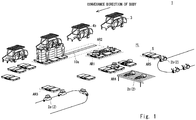
- Fig. 1 is a perspective view schematically showing the workpiece conveyance system according to this embodiment.
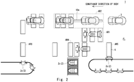
- Fig. 2 is a plan view schematically showing the workpiece conveyance system according to this embodiment.
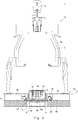
- Fig. 3 is a cross-sectional view of an area in which a first workpiece is assembled in a second workpiece in the workpiece conveyance system according to this embodiment as viewed from a front side of the second workpiece.
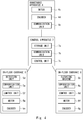
- Fig. 4 is a block diagram of a control system of the workpiece conveyance system according to this embodiment. Note that in Figs. 1 to 3 , members are omitted as appropriate in order to facilitate understanding of the drawings.
- a workpiece conveyance system 1 is suitable, for example, for a facility such as a production line of automobiles, and is used for assembling a first workpiece 2 in a second workpiece 3.
- the first workpieces 2 are, for example, a front assembly 2a constituting a front suspension and its peripheral members of an electric automobile, a rear assembly 2b constituting a rear suspension and its peripheral members thereof, and a battery 2c disposed between the front assembly 2a and the rear assembly 2b.
- the second workpiece 3 is, for example, a body (hereinafter may be denoted by the same reference symbol 3 as that denoting the second workpiece) of an electric automobile.
- the first and the second workpieces 2 and 3 are not limited to the above, and any workpieces that can be fixed to each other may be used as the first and the second workpieces 2 and 3.
- the workpiece conveyance system 1 includes a conveyance apparatus 4, an on-floor carriage 5, an under-floor carriage 6, and a control apparatus 7.
- the conveyance apparatus 4 is configured so that it includes a hanger 4b movable along a rail 4a, and can convey the second workpiece 3 in a state in which the second workpiece 3 is suspended and supported by the hanger 4b.
- the conveyance apparatus 4 may have any configuration in which it can convey the second workpiece 3 above a floor FL of a facility.
- the conveyance apparatus 4 is configured to hold, with the hanger 4b, the second workpieces 3 arranged in advance in the conveyance order and convey them. Further, the conveyance apparatus 4 is configured to detect, by an encoder 4d, a rotational angular velocity of a motor 4c for moving the hanger 4b along the rail 4a and output information indicating the detected rotational angular velocity of the motor 4c to the control apparatus 7 through a communication unit 4e.
- the on-floor carriage 5 moves on the floor FL of the facility to convey the first workpieces 2.
- the on-floor carriage 5 may travel by itself (i.e., autonomously moves) on the floor FL of the facility.
- the on-floor carriage 5 may instead move along a rail or the like laid on the floor FL of the facility or may instead move based on an instruction from the outside.
- a plurality of sets of on-floor carriages travel by themselves on the floor FL of the facility, each of the sets of on-floor carriages comprising the on-floor carriage 5 that conveys the front assembly 2a, the on-floor carriage 5 that conveys the rear assembly 2b, and the on-floor carriage 5 that conveys the battery 2c.
- the number of on-floor carriage 5 constituting a set of on-floor carriages can be changed as appropriate in accordance with the number of first workpieces 2 to be assembled in the second workpiece 3.
- Fig. 5 is a perspective view schematically showing the on-floor carriage according to this embodiment.
- Fig. 6 is a front view schematically showing the on-floor carriage according to this embodiment. Note that, in Figs. 5 and 6 , a state in which the placement part is pushed up is shown by an alternate long and two short dashes line. Further, in Figs. 5 and 6 , the support part is omitted in order to clearly show the state in which the placement part is pushed up.
- the on-floor carriage 5 includes a base 5a, a placement part 5b, a support part 5c, a detection unit 5d, a communication unit 5e, and a control unit 5f.
- the base 5a includes a first step 5g, a second step 5h, and a connection part 5i.
- An upper surface of the first step 5g is a substantially flat surface, and the first step 5g has, for example, a substantially rectangular shape when the on-floor carriage 5 is viewed from the vertical direction.
- the second step 5h and the first step 5g are disposed so that they are spaced from each other in the left and right directions of the on-floor carriage 5, respectively.
- An upper surface of the second step 5h is a substantially flat surface, and the second step 5h has, for example, a substantially rectangular shape when the on-floor carriage 5 is viewed from the vertical direction.
- the substantially flat surface of the first step 5g and the substantially flat surface of the second step 5h are located at substantially the same height.
- connection part 5i connects the first step 5g to the second step 5h.
- the connection part 5i has a substantially U-shape when the on-floor carriage 5 is viewed from the front side thereof, and one end of the connection part 5i is fixed to the first step 5g, and the other end of the connection part 5i is fixed to the second step 5h.
- a penetration part 5j through which an extending/contracting part 6h of an elevating machine 6b described later passes is formed in the connection part 5i.
- Driving wheels 5k and trailing wheels 51 are provided on the lower surfaces of the first step 5g and the second step 5h, respectively, of the base 5a described above.
- Each driving wheel 5k is rotationally driven by a driving force of a motor 5m.
- the rotational angular velocity of the motor 5m is detected by an encoder 5n.
- the first workpiece 2 is placed on the placement part 5b.
- an upper surface of the placement part 5b is a substantially flat surface, and the placement part 5b is disposed so that it can move in the vertical direction with respect to the base 5a.
- the support part 5c can follow movement of the placement part 5b in the vertical direction, and prevents a deflection of the placement part 5b in the horizontal direction.
- the support part 5c includes a pantograph, which is disposed in a recessed part of the connection part 5i. Further, the lower end part of the support part 5c is fixed to the upper surface of the recessed part of the connection part 5i, and the upper end part of the support part 5c is fixed to the lower surface of the placement part 5b.
- the support part 5c may be covered with a cover part 5o.
- the cover part 5o is a cylindrical body formed so as to have a bellows shape, and the lower end part of the cover part 5o is fixed to the upper surface of the recessed part of the connection part 5i, and the upper end part of the cover part 5o is fixed to the lower surface of the placement part 5b.
- the detection unit 5d detects movement of the under-floor carriage 6.
- the detection unit 5d includes, for example, a photoelectric sensor, and is fixed to the on-floor carriage 5 so that the photoelectric sensor can emit a laser beam in a downward direction thereof.
- the detection unit 5d outputs detection information indicating the detected movement of the under-floor carriage 6 to the control unit 5f.
- the detection unit 5d may have any configuration in which it can detect movement of the under-floor carriage 6.
- the communication unit 5e is connected to the control apparatus 7 so that information can be transmitted and received therebetween.
- the control unit 5f controls the motor 5m so that the on-floor carriage 5 travels by itself on a preset path to convey the first workpiece 2 while referring to detection information of the encoder 5n.
- control unit 5f controls the motor 5m so that movement of the on-floor carriage 5 is synchronized with movement of the under-floor carriage 6 based on the detection information input from the detection unit 5d, and the control unit 5f controls the motor 5m so that the on-floor carriage 5 waits in a waiting area AR1 (see Figs. 1 and 2 ) of the facility for waiting before the first workpiece 2 is assembled in the second workpiece 3, and so that the on-floor carriage 5 enters an assembly working area AR2 (see Figs. 1 and 2 ) of the facility for assembling the first workpiece 2 in the second workpiece 3 based on instruction information input from the control apparatus 7.
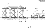
- Fig. 7 is a diagram showing a positional relationship between the on-floor carriage and the under-floor carriage according to this embodiment.
- Fig. 8 is a side view schematically showing the under-floor carriage according to this embodiment.
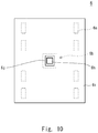
- Fig. 9 is a front view schematically showing the under-floor carriage according to this embodiment.
- Fig. 10 is a plan view schematically showing the under-floor carriage according to this embodiment. Note that Fig. 7 shows on the right side thereof a state immediately after the on-floor carriages 5 are disposed immediately above the respective under-floor carriages 6, and shows on the left side thereof a state in which the on-floor carriages 5 and the under-floor carriages 6 move in synchronization with each other and the first workpieces 2 are pushed up.
- the under-floor carriage 6 travels back and forth in a groove-shaped underfloor space US formed inside the floor FL.
- the underfloor space US is extended along the rail 4a of the conveyance apparatus 4 and the bottom surface of the underfloor space US is a substantially flat surface.
- the three under-floor carriages 6 are arranged in the direction in which the underfloor space US is extended so that they correspond to the number of on-floor carriages 5 constituting a set of on-floor carriages.
- the number of under-floor carriages 6 can be changed as appropriate so as to correspond to the number of on-floor carriages 5 constituting a set of on-floor carriages.
- the under-floor carriage 6 includes a base 6a, the elevating machine 6b, a communication unit 6c, and a control unit 6d.
- the base 6a constitutes a chassis of the under-floor carriage 6, and includes driving wheels 6e on the lower surface of the base 6a.
- Each driving wheel 6e is rotationally driven by a driving force of a motor 6f.
- the rotational angular velocity of the motor 6f is detected by an encoder 6g.
- the elevating machine 6b is fixed to the upper surface of the base 6a.
- the elevating machine 6b includes the extending/contracting part 6h that can extend and contract in the vertical direction of the under-floor carriage 6.
- the extending/contracting part 6h is composed of, for example, a cylinder jack, and has a shape allowing it to be inserted into the penetration part 5j of the on-floor carriage 5.
- the elevating machine 6b described above is covered with a cover 6i, and as shown in Fig. 10 , the extending/contracting part 6h is passed through a penetration part 6j so that it can extend and contract, the penetration part 6j being formed on the upper surface of the cover 6i.
- the elevating machine 6b may have any structure by which it can push up the placement part 5b of the on-floor carriage 5 in a state in which the first workpiece 2 is placed on the placement part 5b, and can pull down the placement part 5b from which the first workpiece 2 has been removed. Further, the elevating machine 6b may be electric or hydraulic.
- the on-floor carriage 5 may include a transmission part 5p protruding downward from the lower surface of the placement part 5b of the on-floor carriage 5.
- the transmission part 5p has, for example, a columnar shape, and is disposed so that it and the penetration part 5j overlap each other when viewed from the vertical direction.
- the communication unit 6c is connected to the control apparatus 7 so that information can be transmitted and received therebetween.
- the control unit 6d controls the motor 6f so that the under-floor carriage 6 travels back and forth in the underfloor space US based on instruction information input from the control apparatus 7 while referring to detection information of the encoder 6g. This operation will be described in detail later. Further, the control unit 6d controls the elevating machine 6b so that the extending/contracting part 6h extends and contracts based on the instruction information input from the control apparatus 7.
- the control apparatus 7 includes a storage unit 7a, a communication unit 7b, and a control unit 7c.
- the storage unit 7a stores, for example, identification information (e.g., information indicating the type of vehicle) of the second workpieces 3 sequentially conveyed by the conveyance apparatus 4, identification information of the first workpiece 2 assembled in the second workpiece 3, assembly position information of the first workpiece 2 with respect to the second workpiece 3.
- identification information e.g., information indicating the type of vehicle
- the communication unit 7b is connected to the communication unit 4e of the conveyance apparatus 4, the communication unit 5e of the on-floor carriage 5, and the communication unit 6c of the under-floor carriage 6 so that information can be transmitted and received therebetween.
- the communication unit 7b of the control apparatus 7 may be connected, for example, through a network, to the communication unit 4e of the conveyance apparatus 4, the communication unit 5e of the on-floor carriage 5, and the communication unit 6c of the under-floor carriage 6 that are mentioned above.
- the control unit 7c generates instruction information for controlling the under-floor carriage 6 so that the under-floor carriage 6 moves in synchronization with movement of the second workpiece 3 based on a result of the detection by the encoder 4d input from the conveyance apparatus 4, and generates instruction information for controlling the on-floor carriage 5 so that the on-floor carriage 5 waits in the waiting area AR1, and so that it enters the assembly working area AR2.
- control unit 7c generates, for example, instruction information for controlling the intervals between the under-floor carriages 6, the amount of extension of the extending/contracting part 6h of the elevating machine 6b, and the like based on identification information of the second workpieces 3 sequentially conveyed by the conveyance apparatus 4, identification information of the first workpiece 2 assembled in the second workpiece 3, and assembly position information of the first workpiece 2 with respect to the second workpiece 3.
- the above instruction information is transmitted to the on-floor carriage 5 or the under-floor carriage 6 through the communication unit 7b.
- the control unit 5f of each of the three on-floor carriages 5 constituting a set of on-floor carriages controls the motor 5m so that the on-floor carriage 5 travels by itself on a preset path in the order of a delivery area AR3 of the front assembly 2a, a delivery area AR4 of the battery 2c, and a delivery area AR5 of the rear assembly 2b.
- the control unit 5f of each of the on-floor carriages 5 controls the motor 5m so that the on-floor carriage 5 travels by itself to the waiting area AR1 and waits there.
- the on-floor carriage 5 that conveys the rear assembly 2b, the on-floor carriage 5 that conveys the battery 2c, and the on-floor carriages 5 that conveys the front assembly 2a are each made to travel by itself so that they are arranged in this order toward the conveyance direction of the body 3.
- the control unit 5f of the on-floor carriage 5 transmits information indicating that the on-floor carriage 5 has reached the waiting area AR1 to the control apparatus 7 through the communication unit 5e of the on-floor carriage 5.
- the control unit 7c of the control apparatus 7 checks whether or not the under-floor carriage 6 is disposed in a starting area of the underfloor space US located opposite to the conveyance direction of the body 3 based on detection information of the encoder 6g of the under-floor carriage 6.
- control unit 7c of the control apparatus 7 checks whether or not the next body 3 that reaches the assembly working area AR2 has come close to a position set in advance for the assembly working area AR2 based on detection information of the encoder 4d transmitted from the conveyance apparatus 4.
- control unit 7c of the control apparatus 7 When the under-floor carriage 6 is disposed in the starting area of the underfloor space US located opposite to the conveyance direction of the body 3, and the body 3 has come close to the position set in advance for the assembly working area AR2, the control unit 7c of the control apparatus 7 generates instruction information for controlling each of the on-floor carriages 5 so that it resumes traveling by itself to a position substantially immediately above the under-floor carriage 6 in the assembly working area AR2, and transmits the generated instruction information to each of the on-floor carriages 5 through the communication unit 7b.
- the three under-floor carriages 6 are disposed in the underfloor space US at desired intervals based on identification information of the body 3 that reaches the assembly working area AR2, identification information of each of the front assembly 2a, the rear assembly 2b, and the battery 2c that are assembled in the body 3, and assembly position information of each of the front assembly 2a, the rear assembly 2b, and the battery 2c with respect to the body 3.
- control unit 7c of the control apparatus 7 waits to generate instruction information for controlling each of the on-floor carriages 5 so that it resumes traveling by itself to the position substantially immediately above the under-floor carriage 6 in the assembly working area AR2.
- the control unit 5f of the on-floor carriage 5 controls the motor 5m so that the on-floor carriage 5 resumes traveling by itself to the position substantially immediately above the under-floor carriage 6 in the assembly working area AR2.
- the on-floor carriage 5 enters the assembling working area AR2 from the side of the underfloor space US opposite to the conveyance direction of the body 3 so that the on-floor carriage 5 straddles the underfloor space US with the first and the second steps 5g and 5h thereof, and as shown in the right side of Fig. 7 , the under-floor carriages 6 are disposed substantially immediately below the respective on-floor carriages 5.
- control unit 7c of the control apparatus 7 checks whether or not the body 3 has reached substantially immediately above the three under-floor carriages 6 based on detection information of the encoder 4d of the conveyance apparatus 4.
- the control unit 7c of the control apparatus 7 generates instruction information for controlling each of the under-floor carriages 6 so that its movement is synchronized with movement of the body 3, and transmits the generated instruction information to each of the under-floor carriages 6 through the communication unit 7b.
- control unit 7c of the control apparatus 7 waits to generate instruction information for controlling each of the under-floor carriages 6 so that its movement is synchronized with movement of the body 3.
- the control unit 6d of the under-floor carriage 6 controls the motor 6f so that movement of the under-floor carriage 6 is synchronized with movement of the body 3.
- the control unit 7c of the control apparatus 7 may generate instruction information for the under-floor carriage 6 so that movement of the under-floor carriage 6 is synchronized with movement of the body 3 based on detection information of the encoder 4d of the conveyance apparatus 4.
- the detection unit 5d of the on-floor carriage 5 detects movement of the under-floor carriage 6 immediately below this on-floor carriage 5, and the control unit 5f of the on-floor carriage 5 controls the motor 5m so that the on-floor carriage 5 moves in synchronization with movement of the under-floor carriage 6 disposed immediately below this on-floor carriage 5 based on the detection information of the detection unit 5d.
- the control unit 6d of the under-floor carriage 6 controls the elevating machine 6b so that the extending/contracting part 6h thereof is extended.
- the extending/contracting part 6h of the elevating machine 6b is extended, as shown in the left side of Fig. 7 , the extending/contracting part 6h passes through the penetration part 5j of the on-floor carriage 5, and the upper end part of the extending/contracting part 6h comes into contact with the placement part 5b of the on-floor carriage 5 through the transmission part 5p, whereby the placement part 5b is pushed up.
- the placement part 5b is supported by the support part 5c, it is possible to prevent a deflection of the placement part 5b.
- control unit 7c of the control apparatus 7 calculates the amount of extension required for the extending/contracting part 6h of the elevating machine 6b of each of the under-floor carriages 6 based on identification information of the body 3 that reaches the assembly working area AR2, identification information of each of the front assembly 2a, the rear assembly 2b, and the battery 2c that are assembled in the body 3, and assembly position information of each of the front assembly 2a, the rear assembly 2b, and the battery 2c with respect to the body 3.
- control unit 7c of the control apparatus 7 generates instruction information for controlling the elevating machine 6b so that the extending/contracting part 6h is extended by the calculated amount of extension, and transmits the generated instruction information to each of the under-floor carriages 6 through the communication unit 7b.
- the control unit 6d of the under-floor carriage 6 controls the elevating machine 6b so that the extending/contracting part 6h is extended by a desired amount of extension based on this instruction information.
- the elevating machine 6b of the under-floor carriage 6 pushes up the front assembly 2a, the rear assembly 2b, or the battery 2c placed on the placement part 5b of the on-floor carriage 5, and it is thus possible to eliminate the need for providing the on-floor carriage 5 with the elevating machine. Therefore, it is possible to configure the workpiece conveyance system 1 at a low cost.
- the control unit 6d of the under-floor carriage 6 controls the elevating machine 6b so that the extending/contracting part 6h contracts when a preset period of time has elapsed after the under-floor carriage 6 starts moving.
- the preset period of time may be set to a period of time that at least allows an operator to assemble the front assembly 2a, the rear assembly 2b, and the battery 2c in the body 3.
- control unit 6d of the under-floor carriage 6 checks whether or not the under-floor carriage 6 has moved a preset distance in the underfloor space US while referring to the encoder 6g.
- the control unit 6d of the under-floor carriage 6 controls the motor 6f so that the under-floor carriage 6 stops.
- control unit 6d of the under-floor carriage 6 continues controlling the motor 6f so that the under-floor carriage 6 moves the preset distance in the underfloor space US while referring to the encoder 6g.
- the preset distance may be set, for example, to a distance which the under-floor carriage 6 travels during a period of time obtained by adding a period of time required until the contraction of the extending/contracting part 6h of the elevating machine 6b is completed to a period of time that at least allows an operator to assemble the front assembly 2a, the rear assembly 2b, and the battery 2c in the body 3.
- the underfloor space US is extended so that it has a length which the under-floor carriage 6 travels during a period of time obtained by adding a period of time required until the contraction of the extending/contracting part 6h of the elevating machine 6b is completed to a period of time that at least allows an operator to assemble the front assembly 2a, the rear assembly 2b, and the battery 2c in the body 3.
- control unit 6d of the under-floor carriage 6 transmits information indicating that the under-floor carriage 6 has stopped to the control apparatus 7 through the communication unit 6c.
- the control unit 7c of the control apparatus 7 checks identification information of the next body 3 that reaches the assembly working area AR2, identification information of each of the front assembly 2a, the rear assembly 2b, and the battery 2c that are assembled in the body 3, and assembly position information of each of the front assembly 2a, the rear assembly 2b, and the battery 2c with respect to the body 3 based on identification information of the bodies 3 sequentially conveyed by the conveyance apparatus 4, identification information of each of the front assembly 2a, the rear assembly 2b, and the battery 2c that are assembled in the body 3, and assembly position information of each of the front assembly 2a, the rear assembly 2b, and the battery 2c with respect to the body 3.
- the control unit 7c of the control apparatus 7 calculates optimum intervals among the three under-floor carriages 6 for assembling the front assembly 2a, the rear assembly 2b, and the battery 2c in the body 3 based on identification information of the next body 3 that reaches the assembly working area AR2, identification information of each of the front assembly 2a, the rear assembly 2b, and the battery 2c that are assembled in the body 3, and assembly position information of each of the front assembly 2a, the rear assembly 2b, and the battery 2c with respect to this body 3. Then the control unit 7c of the control apparatus 7 generates instruction information for controlling each of the three under-floor carriages 6 so that they are disposed in the starting area of the underfloor space US at the calculated intervals.
- the control unit 7c of the control apparatus 7 transmits, to each of the three under-floor carriages 6, the instruction information for controlling each of the three under-floor carriages 6 so that they are disposed in the starting area of the underfloor space US at desired intervals through the communication unit 7b.
- each of the three under-floor carriage 6 When the communication unit 6c of each of the three under-floor carriage 6 receives the instruction information for controlling each of the three under-floor carriages 6 so that they are disposed in the starting area of the underfloor space US at desired intervals, the control unit 6d of each of the three under-floor carriages 6 controls the motor 6f while referring to the encoder 6g so that the three under-floor carriages 6 return to the starting area of the underfloor space US while leaving desired intervals among them.
- the three under-floor carriages 6 can be disposed in the starting area of the underfloor space US at desired intervals in advance based on, for example, assembly position information of each of the front assembly 2a, the rear assembly 2b, and the battery 2c with respect to the next body 3 to be conveyed. Therefore, even when the combination of the body 3 and the front assembly 2a, the rear assembly 2b, and the battery 2c varies due to the conveyance order, the front assembly 2a, the rear assembly 2b, and the battery 2c can be properly disposed at respective assembly positions with respect to the body 3.
- control unit 5f of the on-floor carriage 5 checks whether or not the on-floor carriage 5 has moved the above-described preset distance after it starts synchronization of the movement of the on-floor carriage 5 with the movement of the under-floor carriage 6 while referring to detection information of the encoder 5n.
- the control unit 5f of the on-floor carriage 5 controls the motor 5m so that the synchronization between the movement of the on-floor carriage 5 and the movement of the under-floor carriage 6 disposed immediately below the on-floor carriage 5 is released and the on-floor carriage 5 travels by itself on a preset path to receive the new front assembly 2a, the new rear assembly 2b, and the new battery 2c.
- control unit 5f of the on-floor carriage 5 controls the motor 5m while referring to detection information of the detection unit 5d so that the synchronization between the movement of the on-floor carriage 5 and the movement of the under-floor carriage 6 disposed immediately below the on-floor carriage 5 continues.
- the elevating machine 6b of the under-floor carriage 6 pushes up the front assembly 2a, the rear assembly 2b, or the battery 2c placed on the placement part 5b of the on-floor carriage 5, and it is thus possible to eliminate the need for providing the on-floor carriage 5 with the elevating machine. Therefore, it is possible to configure the workpiece conveyance system 1 at a low cost.
- the on-floor carriage 5 has a simple structure in which the penetration part 5j through which the extending/contracting part 6h of the elevating machine 6b of the under-floor carriage 6 passes is provided, it is possible to configure the workpiece conveyance system 1 at a low cost.
- the on-floor carriage 5, the under-floor carriage 6, and the workpiece conveyance method according to this embodiment it is possible to synchronize the movement of the on-floor carriage 5 and the movement of the under-floor carriage 6 with the movement of the body 3 and assemble the front assembly 2a, the rear assembly 2b, and the battery 2c in the body 3, and it is thus possible to make the conveyance speed of the body 3 substantially constant. Therefore, it is possible to improve the productivity of a cell automobile.
- the three under-floor carriages 6 can be disposed in the starting area of the underfloor space US at desired intervals in advance based on the assembly position information of the front assembly 2a, the rear assembly 2b, and the battery 2c with respect to the next body 3 to be conveyed. Therefore, even when the combination of the body 3 and the front assembly 2a, the rear assembly 2b, and the battery 2c varies due to the conveyance order, the front assembly 2a, the rear assembly 2b, and the battery 2c can be properly disposed at respective assembly positions with respect to the body 3.
- an opening of the underfloor space US may be covered with a lid 10.
- the lid 10 may include a penetration part 10a through which the extending/contracting part 6h of the elevating machine 6b of the under-floor carriage 6 passes, the penetration part 10a being formed along the rail 4a of the conveyance apparatus 4.
- the workpiece conveyance system 1 may include stages 11 on the floor FL along both sides of the underfloor space US.
- upper surfaces of the stages 11 may be substantially flat surfaces having a height substantially equal to the height of each of the first and the second steps 5g and 5h of the on-floor carriage 5.
- the workpiece conveyance system 1 may include a pressing part 12 that prevents the uplift of the on-floor carriage 5.
- the pressing part 12 may include, for example, a roller 12a which is disposed so that it protrudes outward from the on-floor carriage 5 and which is rotated around a rotation axis extending in the vertical direction, and a groove part 12b which is formed on the stage 11 and into which a part of the roller 12a is inserted.
- the roller 12a is rotated in accordance with the self-traveling of the on-floor carriage 5, and when the on-floor carriage 5 is uplifted, the roller 12a comes into contact with the groove part 12b and thus the uplift of the on-floor carriage 5 can be prevented.
- the pressing part 12 may have any structure in which it is possible to prevent the uplift of the on-floor carriage 5 when the on-floor carriage 5 travels by itself on the underfloor space US.
- the first workpiece 2 is placed on the placement part 5b of each of the on-floor carriages 5
- the first workpiece 2 may not be placed on the placement part 5b of each of the on-floor carriages 5 in accordance with the second workpiece 3 that is conveyed.
- a facility to which the workpiece conveyance system 1 is applied is not limited, and it is also possible to apply the workpiece conveyance system 1 to a facility for assembling the first workpiece 2 in the second workpiece 3 by pushing up the first workpiece 2.
- position information of the second workpiece 3 i.e., the hanger 4b
- position information of the on-floor carriage 5, and position information of the under-floor carriage 6 are acquired based on detection information of the encoder.
- position information of the hanger 4b, position information of the on-floor carriage 5, and position information of the under-floor carriage 6 may be acquired based on position information of a Global Positioning System (GPS) or the like.
- position information of the hanger 4b, position information of the on-floor carriage 5, and position information of the under-floor carriage 6 may be detected by a detection sensor disposed in the facility.
- GPS Global Positioning System
- the movement of the on-floor carriage 5 is synchronized with the movement of the under-floor carriage 6 by using the detection unit 5d of the on-floor carriage 5.
- the on-floor carriage 5 and the under-floor carriage 6 may be connected to each other by the connection part at the time when the movement of the on-floor carriage 5 is synchronized with the movement of the under-floor carriage 6, and by using the driving force of one of the on-floor carriage 5 and the under-floor carriage 6, the other one of them may be moved.
- the under-floor carriage 6 includes one elevating machine 6b, but it may instead include a plurality of elevating machines 6b.
- the elevating machine 6b is mounted on the under-floor carriage 6, but may instead be disposed in the facility. In this case, when the first workpiece 2 is assembled in the second workpiece 3, the movement of the second workpiece 3 may be temporarily stopped.
- the operations of the on-floor carriage 5 and the under-floor carriage 6 in the above embodiment are merely examples, and it is sufficient that the on-floor carriage 5 and the under-floor carriage 6 be operated so that the first workpiece 2 can be assembled in the second workpiece 3.
- control unit 5f of the on-floor carriage 5, the control unit 6d of the under-floor carriage 6, and the control unit 7c of the control apparatus 7 may be configured of computers, and the respective computers may cause Central Processing Units (CPUs) thereof to execute computer programs to control the conveyance apparatus 4, the on-floor carriage 5, and the under-floor carriage 6.
- CPUs Central Processing Units
- Non-transitory computer readable media include any type of tangible storage media.
- Examples of non-transitory computer readable media include magnetic storage media (such as floppy disks, magnetic tapes, hard disk drives, etc.), optical magnetic storage media (e.g., magneto-optical disks), CD-ROM (compact disc read only memory), CD-R (compact disc recordable), CD-R/W (compact disc rewritable), and semiconductor memories (such as mask ROM, PROM (programmable ROM), EPROM (erasable PROM), flash ROM, RAM (random access memory), etc.).
- magnetic storage media such as floppy disks, magnetic tapes, hard disk drives, etc.
- optical magnetic storage media e.g., magneto-optical disks
- CD-ROM compact disc read only memory
- CD-R compact disc recordable
- CD-R/W compact disc rewritable
- semiconductor memories such as mask ROM, PROM (programmable ROM), EPROM (erasable PROM), flash
- the program(s) may be provided to a computer using any type of transitory computer readable media.
- Examples of transitory computer readable media include electric signals, optical signals, and electromagnetic waves.
- Transitory computer readable media can provide the program(s) to a computer via a wired communication line (e.g., electric wires, and optical fibers) or a wireless communication line.
Landscapes
- Engineering & Computer Science (AREA)
- Mechanical Engineering (AREA)
- Transportation (AREA)
- Structural Engineering (AREA)
- Life Sciences & Earth Sciences (AREA)
- Geology (AREA)
- Combustion & Propulsion (AREA)
- Manufacturing & Machinery (AREA)
- Chemical & Material Sciences (AREA)
- Civil Engineering (AREA)
- Automobile Manufacture Line, Endless Track Vehicle, Trailer (AREA)
- Automatic Assembly (AREA)
- Intermediate Stations On Conveyors (AREA)
Abstract
Description
- The present disclosure relates to a workpiece conveyance system, an on-floor carriage, an under-floor carriage, and a workpiece conveyance method.
- For example, in a workpiece conveyance system used in a production line of automobiles or the like, self-propelled carriages are used to convey workpieces to be assembled. Such a carriage includes, as disclosed in, for example,
Japanese Unexamined Patent Application Publication No. 2019-3241 - The applicant has however found the following problem. As described above, all the carriages include elevating machines in a general workpiece conveyance system. This causes a problem that the whole workpiece conveyance system becomes expensive.
- The present disclosure has been made in view of the above-described problem and provides a workpiece conveyance system, an on-floor carriage, an under-floor carriage, and a workpiece conveyance method that can configure a workpiece conveyance system at a low cost.
- A first exemplary aspect is a workpiece conveyance system configured to convey a first workpiece inside a facility and raise the first workpiece, the workpiece conveyance system including:
- an on-floor carriage configured to be movable on a floor of the facility, the on-floor carriage including a placement part on which the first workpiece is placed; and
- an elevating machine configured to push up the placement part, the elevating machine being configured separately from the on-floor carriage.
- By this structure, it is possible to raise (i.e., push up) the first workpiece placed on the placement part of the on-floor carriage by means of the elevating machine, and it is thus possible to eliminate the need for providing the on-floor carriage with the elevating machine. Therefore, it is possible to configure the workpiece conveyance system at a low cost.
- The workpiece conveyance system may further include an under-floor carriage disposed under the floor of the facility, the under-floor carriage including the elevating machine,
in which movement of the on-floor carriage and movement of the under-floor carriage may be synchronized with each other in a state in which they are stacked on each other in a vertical direction. - By this structure, it is possible to push up the first workpiece while moving the on-floor carriage.
- In the workpiece conveyance system described above, the under-floor carriage may be disposed below a conveyance apparatus configured to convey a second workpiece in which the first workpiece is assembled, movement of the under-floor carriage being synchronized with the conveyance of the second workpiece.
- By this structure, it is possible to synchronize movement of the on-floor carriage and movement of the under-floor carriage with movement of the second workpiece and assemble the first workpiece in the second workpiece, and it is thus possible to make the conveyance speed of the second workpiece substantially constant.
- The workpiece conveyance system described above may include:
- a plurality of the on-floor carriages each configured to convey a plurality of the first workpieces individually, the plurality of the first workpieces being assembled in the one second workpiece; and
- a plurality of the under-floor carriages,
- in which the on-floor carriages or the under-floor carriages may travel at intervals based on assembly position information of each of the first workpieces that are assembled in the second workpiece.
- By this structure, the first workpiece can be disposed at a proper assembly position with respect to the second workpiece.
- In the workpiece conveyance system described above, the elevating machine may operate based on the assembly position information of each of the first workpieces that are assembled in the second workpiece.
- By this structure, it is possible to push up the first workpiece to a proper assembly position with respect to the second workpiece.
- In the workpiece conveyance system described above, the on-floor carriage may include a penetration part through which an extending/contracting part of the elevating machine is passed.
- In the workpiece conveyance system described above, the on-floor carriage may include a support part capable of following movement of the placement part in the vertical direction, the support part preventing a deflection of the placement part in a horizontal direction.
- Another exemplary aspect is an on-floor carriage configured to move on a floor of a facility and convey a workpiece, the on-floor carriage including:
- a placement part on which the workpiece is placed; and
- a penetration part through which an extending/contracting part of an elevating machine is passed, the elevating machine being configured separately from the on-floor carriage,
- in which the extending/contracting part pushes up the placement part.
- By this structure, it is possible to push up the workpiece placed on the placement part of the on-floor carriage by means of the elevating machine, and it is thus possible to eliminate the need for providing the on-floor carriage with the elevating machine.
- Another exemplary aspect is an under-floor carriage configured to move under a floor of a facility in synchronization with movement of an on-floor carriage in a state in which they are stacked on each other in a vertical direction, the on-floor carriage being configured to move on the floor of the facility and convey a workpiece and including a placement part on which the workpiece is placed, the under-floor carriage including an elevating machine configured to push up the placement part.
- By this structure, it is possible to push up the workpiece placed on the placement part of the on-floor carriage by means of the elevating machine, and it is thus possible to eliminate the need for providing the on-floor carriage with the elevating machine.
- Another exemplary aspect is a workpiece conveyance method including:
- moving a carriage in a state in which a workpiece is placed on a placement part of the carriage, thereby conveying the workpiece; and
- pushing up the placement part by means of an elevating machine configured separately from the carriage, thereby raising the workpiece.
- In this way, it is possible to push up the workpiece placed on the placement part of the on-floor carriage by means of the elevating machine, and it is thus possible to eliminate the need for providing the on-floor carriage with the elevating machine.
- According to the present disclosure, it is possible to provide a workpiece conveyance system, an on-floor carriage, an under-floor carriage, and a workpiece conveyance method that can configure a workpiece conveyance system at a low cost.
- The above and other objects, features and advantages of the present disclosure will become more fully understood from the detailed description given hereinbelow and the accompanying drawings which are given by way of illustration only, and thus are not to be considered as limiting the present disclosure.
-
-
Fig. 1 is a perspective view schematically showing a workpiece conveyance system according to an embodiment; -
Fig. 2 is a plan view schematically showing the workpiece conveyance system according to the embodiment; -
Fig. 3 is a cross-sectional view of an area in which a first workpiece is assembled in a second workpiece in the workpiece conveyance system according to the embodiment as viewed from a front side of the second workpiece; -
Fig. 4 is a block diagram of a control system of the workpiece conveyance system according to the embodiment; -
Fig. 5 is a perspective view schematically showing an on-floor carriage according to the embodiment; -
Fig. 6 is a front view schematically showing the on-floor carriage according to the embodiment; -
Fig. 7 is a diagram showing a positional relationship between the on-floor carriage and an under-floor carriage according to the embodiment; -
Fig. 8 is a side view schematically showing the under-floor carriage according to the embodiment; -
Fig. 9 is a front view schematically showing the under-floor carriage according to the embodiment; -
Fig. 10 is a plan view schematically showing the under-floor carriage according to the embodiment; and -
Fig. 11 is a cross-sectional view of an area in which a first workpiece is assembled in a second workpiece in a workpiece conveyance system according to another embodiment as viewed from a front side of the second workpiece. - A specific embodiment to which the present disclosure is applied will be described hereinafter in detail with reference to the drawings. However, the present disclosure is not limited to the embodiment shown below. Further, for the clarification of the explanation, the following descriptions and the drawings are simplified as appropriate.
- First, a configuration of a workpiece conveyance system according to this embodiment will be described.
Fig. 1 is a perspective view schematically showing the workpiece conveyance system according to this embodiment.Fig. 2 is a plan view schematically showing the workpiece conveyance system according to this embodiment.Fig. 3 is a cross-sectional view of an area in which a first workpiece is assembled in a second workpiece in the workpiece conveyance system according to this embodiment as viewed from a front side of the second workpiece.Fig. 4 is a block diagram of a control system of the workpiece conveyance system according to this embodiment. Note that inFigs. 1 to 3 , members are omitted as appropriate in order to facilitate understanding of the drawings. - A
workpiece conveyance system 1 according to this embodiment is suitable, for example, for a facility such as a production line of automobiles, and is used for assembling afirst workpiece 2 in asecond workpiece 3. Here, thefirst workpieces 2 are, for example, afront assembly 2a constituting a front suspension and its peripheral members of an electric automobile, arear assembly 2b constituting a rear suspension and its peripheral members thereof, and abattery 2c disposed between thefront assembly 2a and therear assembly 2b. - Further, the
second workpiece 3 is, for example, a body (hereinafter may be denoted by thesame reference symbol 3 as that denoting the second workpiece) of an electric automobile. However, the first and thesecond workpieces second workpieces - As shown in
Figs. 1 to 4 , theworkpiece conveyance system 1 includes aconveyance apparatus 4, an on-floor carriage 5, an under-floor carriage 6, and a control apparatus 7. As shown inFig. 3 , theconveyance apparatus 4 is configured so that it includes ahanger 4b movable along arail 4a, and can convey thesecond workpiece 3 in a state in which thesecond workpiece 3 is suspended and supported by thehanger 4b. However, theconveyance apparatus 4 may have any configuration in which it can convey thesecond workpiece 3 above a floor FL of a facility. - At this time, the
conveyance apparatus 4 is configured to hold, with thehanger 4b, thesecond workpieces 3 arranged in advance in the conveyance order and convey them. Further, theconveyance apparatus 4 is configured to detect, by anencoder 4d, a rotational angular velocity of amotor 4c for moving thehanger 4b along therail 4a and output information indicating the detected rotational angular velocity of themotor 4c to the control apparatus 7 through acommunication unit 4e. - As shown in
Figs. 1 and2 , the on-floor carriage 5 moves on the floor FL of the facility to convey thefirst workpieces 2. At this time, in order to convey thefirst workpieces 2, the on-floor carriage 5 may travel by itself (i.e., autonomously moves) on the floor FL of the facility. However, the on-floor carriage 5 may instead move along a rail or the like laid on the floor FL of the facility or may instead move based on an instruction from the outside. - In this embodiment, for example, a plurality of sets of on-floor carriages travel by themselves on the floor FL of the facility, each of the sets of on-floor carriages comprising the on-
floor carriage 5 that conveys thefront assembly 2a, the on-floor carriage 5 that conveys therear assembly 2b, and the on-floor carriage 5 that conveys thebattery 2c. However, the number of on-floor carriage 5 constituting a set of on-floor carriages can be changed as appropriate in accordance with the number offirst workpieces 2 to be assembled in thesecond workpiece 3. -
Fig. 5 is a perspective view schematically showing the on-floor carriage according to this embodiment.Fig. 6 is a front view schematically showing the on-floor carriage according to this embodiment. Note that, inFigs. 5 and6 , a state in which the placement part is pushed up is shown by an alternate long and two short dashes line. Further, inFigs. 5 and6 , the support part is omitted in order to clearly show the state in which the placement part is pushed up. - For example, as shown in
Figs. 3 to 6 , the on-floor carriage 5 includes abase 5a, aplacement part 5b, asupport part 5c, adetection unit 5d, acommunication unit 5e, and acontrol unit 5f. Thebase 5a includes afirst step 5g, asecond step 5h, and aconnection part 5i. - An upper surface of the
first step 5g is a substantially flat surface, and thefirst step 5g has, for example, a substantially rectangular shape when the on-floor carriage 5 is viewed from the vertical direction. Thesecond step 5h and thefirst step 5g are disposed so that they are spaced from each other in the left and right directions of the on-floor carriage 5, respectively. An upper surface of thesecond step 5h is a substantially flat surface, and thesecond step 5h has, for example, a substantially rectangular shape when the on-floor carriage 5 is viewed from the vertical direction. The substantially flat surface of thefirst step 5g and the substantially flat surface of thesecond step 5h are located at substantially the same height. - The
connection part 5i connects thefirst step 5g to thesecond step 5h. Theconnection part 5i has a substantially U-shape when the on-floor carriage 5 is viewed from the front side thereof, and one end of theconnection part 5i is fixed to thefirst step 5g, and the other end of theconnection part 5i is fixed to thesecond step 5h. Apenetration part 5j through which an extending/contracting part 6h of an elevatingmachine 6b described later passes is formed in theconnection part 5i. - Driving
wheels 5k and trailingwheels 51 are provided on the lower surfaces of thefirst step 5g and thesecond step 5h, respectively, of thebase 5a described above. Eachdriving wheel 5k is rotationally driven by a driving force of a motor 5m. At this time, the rotational angular velocity of the motor 5m is detected by anencoder 5n. - The
first workpiece 2 is placed on theplacement part 5b. For example, an upper surface of theplacement part 5b is a substantially flat surface, and theplacement part 5b is disposed so that it can move in the vertical direction with respect to thebase 5a. Thesupport part 5c can follow movement of theplacement part 5b in the vertical direction, and prevents a deflection of theplacement part 5b in the horizontal direction. - As shown in
Fig. 3 , for example, thesupport part 5c includes a pantograph, which is disposed in a recessed part of theconnection part 5i. Further, the lower end part of thesupport part 5c is fixed to the upper surface of the recessed part of theconnection part 5i, and the upper end part of thesupport part 5c is fixed to the lower surface of theplacement part 5b. - It should be noted that the
support part 5c may be covered with a cover part 5o. The cover part 5o is a cylindrical body formed so as to have a bellows shape, and the lower end part of the cover part 5o is fixed to the upper surface of the recessed part of theconnection part 5i, and the upper end part of the cover part 5o is fixed to the lower surface of theplacement part 5b. By this structure, even if an operator drops a bolt or the like onto thebase 5a when he/she assembles thefirst workpiece 2 in thesecond workpiece 3, it is possible to prevent the bolt or the like from entering thesupport part 5c. - The
detection unit 5d detects movement of the under-floor carriage 6. Thedetection unit 5d includes, for example, a photoelectric sensor, and is fixed to the on-floor carriage 5 so that the photoelectric sensor can emit a laser beam in a downward direction thereof. Thedetection unit 5d outputs detection information indicating the detected movement of the under-floor carriage 6 to thecontrol unit 5f. However, thedetection unit 5d may have any configuration in which it can detect movement of the under-floor carriage 6. - The
communication unit 5e is connected to the control apparatus 7 so that information can be transmitted and received therebetween. Thecontrol unit 5f controls the motor 5m so that the on-floor carriage 5 travels by itself on a preset path to convey thefirst workpiece 2 while referring to detection information of theencoder 5n. - At this time, the
control unit 5f controls the motor 5m so that movement of the on-floor carriage 5 is synchronized with movement of the under-floor carriage 6 based on the detection information input from thedetection unit 5d, and thecontrol unit 5f controls the motor 5m so that the on-floor carriage 5 waits in a waiting area AR1 (seeFigs. 1 and2 ) of the facility for waiting before thefirst workpiece 2 is assembled in thesecond workpiece 3, and so that the on-floor carriage 5 enters an assembly working area AR2 (seeFigs. 1 and2 ) of the facility for assembling thefirst workpiece 2 in thesecond workpiece 3 based on instruction information input from the control apparatus 7. These operations will be described in detail later. -
Fig. 7 is a diagram showing a positional relationship between the on-floor carriage and the under-floor carriage according to this embodiment.Fig. 8 is a side view schematically showing the under-floor carriage according to this embodiment.Fig. 9 is a front view schematically showing the under-floor carriage according to this embodiment.Fig. 10 is a plan view schematically showing the under-floor carriage according to this embodiment. Note thatFig. 7 shows on the right side thereof a state immediately after the on-floor carriages 5 are disposed immediately above the respective under-floor carriages 6, and shows on the left side thereof a state in which the on-floor carriages 5 and the under-floor carriages 6 move in synchronization with each other and thefirst workpieces 2 are pushed up. - As shown in
Figs. 3 and7 , under the assembly working area AR2 shown inFigs. 1 and2 , the under-floor carriage 6 travels back and forth in a groove-shaped underfloor space US formed inside the floor FL. The underfloor space US is extended along therail 4a of theconveyance apparatus 4 and the bottom surface of the underfloor space US is a substantially flat surface. - It should be noted that, in this embodiment, as shown in
Fig. 7 , the three under-floor carriages 6 are arranged in the direction in which the underfloor space US is extended so that they correspond to the number of on-floor carriages 5 constituting a set of on-floor carriages. However, the number of under-floor carriages 6 can be changed as appropriate so as to correspond to the number of on-floor carriages 5 constituting a set of on-floor carriages. - For example, as shown in
Figs. 8 to 10 , the under-floor carriage 6 includes abase 6a, the elevatingmachine 6b, acommunication unit 6c, and acontrol unit 6d. Thebase 6a constitutes a chassis of the under-floor carriage 6, and includes drivingwheels 6e on the lower surface of thebase 6a. Eachdriving wheel 6e is rotationally driven by a driving force of amotor 6f. At this time, the rotational angular velocity of themotor 6f is detected by anencoder 6g. - The elevating
machine 6b is fixed to the upper surface of thebase 6a. The elevatingmachine 6b includes the extending/contracting part 6h that can extend and contract in the vertical direction of the under-floor carriage 6. The extending/contracting part 6h is composed of, for example, a cylinder jack, and has a shape allowing it to be inserted into thepenetration part 5j of the on-floor carriage 5. The elevatingmachine 6b described above is covered with acover 6i, and as shown inFig. 10 , the extending/contracting part 6h is passed through apenetration part 6j so that it can extend and contract, thepenetration part 6j being formed on the upper surface of thecover 6i. - However, the elevating
machine 6b may have any structure by which it can push up theplacement part 5b of the on-floor carriage 5 in a state in which thefirst workpiece 2 is placed on theplacement part 5b, and can pull down theplacement part 5b from which thefirst workpiece 2 has been removed. Further, the elevatingmachine 6b may be electric or hydraulic. - It should be noted that, as shown in
Fig. 3 and the like, the on-floor carriage 5 may include atransmission part 5p protruding downward from the lower surface of theplacement part 5b of the on-floor carriage 5. Thetransmission part 5p has, for example, a columnar shape, and is disposed so that it and thepenetration part 5j overlap each other when viewed from the vertical direction. - By the aforementioned structure, when the extending/
contracting part 6h of the elevatingmachine 6b is extended, it is possible to push up theplacement part 5b through thetransmission part 5p. Therefore, as compared with a case in which thetransmission part 5p is not provided, it is possible to reduce the amount of extension of the elevatingmachine 6b when theplacement part 5b is pushed up to a predetermined height, and accordingly it is possible to reduce the size of the elevatingmachine 6b. - The
communication unit 6c is connected to the control apparatus 7 so that information can be transmitted and received therebetween. Thecontrol unit 6d controls themotor 6f so that the under-floor carriage 6 travels back and forth in the underfloor space US based on instruction information input from the control apparatus 7 while referring to detection information of theencoder 6g. This operation will be described in detail later. Further, thecontrol unit 6d controls the elevatingmachine 6b so that the extending/contracting part 6h extends and contracts based on the instruction information input from the control apparatus 7. - As shown in
Fig. 4 , the control apparatus 7 includes astorage unit 7a, acommunication unit 7b, and acontrol unit 7c. Thestorage unit 7a stores, for example, identification information (e.g., information indicating the type of vehicle) of thesecond workpieces 3 sequentially conveyed by theconveyance apparatus 4, identification information of thefirst workpiece 2 assembled in thesecond workpiece 3, assembly position information of thefirst workpiece 2 with respect to thesecond workpiece 3. - The
communication unit 7b is connected to thecommunication unit 4e of theconveyance apparatus 4, thecommunication unit 5e of the on-floor carriage 5, and thecommunication unit 6c of the under-floor carriage 6 so that information can be transmitted and received therebetween. Thecommunication unit 7b of the control apparatus 7 may be connected, for example, through a network, to thecommunication unit 4e of theconveyance apparatus 4, thecommunication unit 5e of the on-floor carriage 5, and thecommunication unit 6c of the under-floor carriage 6 that are mentioned above. - The
control unit 7c generates instruction information for controlling the under-floor carriage 6 so that the under-floor carriage 6 moves in synchronization with movement of thesecond workpiece 3 based on a result of the detection by theencoder 4d input from theconveyance apparatus 4, and generates instruction information for controlling the on-floor carriage 5 so that the on-floor carriage 5 waits in the waiting area AR1, and so that it enters the assembly working area AR2. - Further, the
control unit 7c generates, for example, instruction information for controlling the intervals between the under-floor carriages 6, the amount of extension of the extending/contracting part 6h of the elevatingmachine 6b, and the like based on identification information of thesecond workpieces 3 sequentially conveyed by theconveyance apparatus 4, identification information of thefirst workpiece 2 assembled in thesecond workpiece 3, and assembly position information of thefirst workpiece 2 with respect to thesecond workpiece 3. The above instruction information is transmitted to the on-floor carriage 5 or the under-floor carriage 6 through thecommunication unit 7b. - Next, a procedure of assembling the
front assembly 2a, therear assembly 2b, and thebattery 2c in abody 3 by using theworkpiece conveyance system 1 according to this embodiment will be described. First, for example, thecontrol unit 5f of each of the three on-floor carriages 5 constituting a set of on-floor carriages controls the motor 5m so that the on-floor carriage 5 travels by itself on a preset path in the order of a delivery area AR3 of thefront assembly 2a, a delivery area AR4 of thebattery 2c, and a delivery area AR5 of therear assembly 2b. - Next, when the
front assembly 2a, thebattery 2c, and therear assembly 2b are placed on theplacement part 5b of each of the on-floor carriages 5 in an order starting from the leading on-floor carriage 5, thecontrol unit 5f of each of the on-floor carriages 5 controls the motor 5m so that the on-floor carriage 5 travels by itself to the waiting area AR1 and waits there. - At this time, in the waiting area AR1, the on-
floor carriage 5 that conveys therear assembly 2b, the on-floor carriage 5 that conveys thebattery 2c, and the on-floor carriages 5 that conveys thefront assembly 2a are each made to travel by itself so that they are arranged in this order toward the conveyance direction of thebody 3. - When the on-
floor carriage 5 reaches the waiting area AR1, thecontrol unit 5f of the on-floor carriage 5 transmits information indicating that the on-floor carriage 5 has reached the waiting area AR1 to the control apparatus 7 through thecommunication unit 5e of the on-floor carriage 5. When thecommunication unit 7b of the control apparatus 7 receives the information indicating that the on-floor carriage 5 has reached the waiting area AR1, thecontrol unit 7c of the control apparatus 7 checks whether or not the under-floor carriage 6 is disposed in a starting area of the underfloor space US located opposite to the conveyance direction of thebody 3 based on detection information of theencoder 6g of the under-floor carriage 6. - Then the
control unit 7c of the control apparatus 7 checks whether or not thenext body 3 that reaches the assembly working area AR2 has come close to a position set in advance for the assembly working area AR2 based on detection information of theencoder 4d transmitted from theconveyance apparatus 4. - When the under-
floor carriage 6 is disposed in the starting area of the underfloor space US located opposite to the conveyance direction of thebody 3, and thebody 3 has come close to the position set in advance for the assembly working area AR2, thecontrol unit 7c of the control apparatus 7 generates instruction information for controlling each of the on-floor carriages 5 so that it resumes traveling by itself to a position substantially immediately above the under-floor carriage 6 in the assembly working area AR2, and transmits the generated instruction information to each of the on-floor carriages 5 through thecommunication unit 7b. - At this time, the three under-
floor carriages 6 are disposed in the underfloor space US at desired intervals based on identification information of thebody 3 that reaches the assembly working area AR2, identification information of each of thefront assembly 2a, therear assembly 2b, and thebattery 2c that are assembled in thebody 3, and assembly position information of each of thefront assembly 2a, therear assembly 2b, and thebattery 2c with respect to thebody 3. - Meanwhile, when the under-
floor carriage 6 is not disposed in the starting area of the underfloor space US located opposite to the conveyance direction of thebody 3, or thebody 3 has not come close to the position set in advance for the assembly working area AR2, thecontrol unit 7c of the control apparatus 7 waits to generate instruction information for controlling each of the on-floor carriages 5 so that it resumes traveling by itself to the position substantially immediately above the under-floor carriage 6 in the assembly working area AR2. - When the
communication unit 5e of the on-floor carriage 5 receives the instruction information, thecontrol unit 5f of the on-floor carriage 5 controls the motor 5m so that the on-floor carriage 5 resumes traveling by itself to the position substantially immediately above the under-floor carriage 6 in the assembly working area AR2. At this time, the on-floor carriage 5 enters the assembling working area AR2 from the side of the underfloor space US opposite to the conveyance direction of thebody 3 so that the on-floor carriage 5 straddles the underfloor space US with the first and thesecond steps Fig. 7 , the under-floor carriages 6 are disposed substantially immediately below the respective on-floor carriages 5. - Next, the
control unit 7c of the control apparatus 7 checks whether or not thebody 3 has reached substantially immediately above the three under-floor carriages 6 based on detection information of theencoder 4d of theconveyance apparatus 4. When thebody 3 reaches substantially immediately above the three under-floor carriages 6, thecontrol unit 7c of the control apparatus 7 generates instruction information for controlling each of the under-floor carriages 6 so that its movement is synchronized with movement of thebody 3, and transmits the generated instruction information to each of the under-floor carriages 6 through thecommunication unit 7b. - On the other hand, when the
body 3 has not reached substantially immediately above the three under-floor carriages 6, thecontrol unit 7c of the control apparatus 7 waits to generate instruction information for controlling each of the under-floor carriages 6 so that its movement is synchronized with movement of thebody 3. - When the
communication unit 6c of the under-floor carriage 6 receives the instruction information, thecontrol unit 6d of the under-floor carriage 6 controls themotor 6f so that movement of the under-floor carriage 6 is synchronized with movement of thebody 3. At this time, when the speed at which theconveyance apparatus 4 conveys thebody 3 is constant, it is possible to easily move the under-floor carriage 6 so that its movement is synchronized with the movement of thebody 3. On the other hand, when the speed at which theconveyance apparatus 4 conveys thebody 3 is variable, thecontrol unit 7c of the control apparatus 7 may generate instruction information for the under-floor carriage 6 so that movement of the under-floor carriage 6 is synchronized with movement of thebody 3 based on detection information of theencoder 4d of theconveyance apparatus 4. - When the under-
floor carriage 6 starts moving so that its movement is synchronized with movement of thebody 3, thedetection unit 5d of the on-floor carriage 5 detects movement of the under-floor carriage 6 immediately below this on-floor carriage 5, and thecontrol unit 5f of the on-floor carriage 5 controls the motor 5m so that the on-floor carriage 5 moves in synchronization with movement of the under-floor carriage 6 disposed immediately below this on-floor carriage 5 based on the detection information of thedetection unit 5d. - At this time, movement of the on-
floor carriage 5 and movement of the under-floor carriage 6 are synchronized with each other so that thepenetration part 5j of the on-floor carriage 5 and the extending/contracting part 6h of the under-floor carriage 6 substantially overlap each other when viewed from the vertical direction. Then, as shown inFig. 3 , an operator gets on thefirst step 5g or thesecond step 5h of the on-floor carriage 5 and moves together with thefront assembly 2a, therear assembly 2b, thebattery 2c, and thebody 3. - At the same time, the
control unit 6d of the under-floor carriage 6 controls the elevatingmachine 6b so that the extending/contracting part 6h thereof is extended. When the extending/contracting part 6h of the elevatingmachine 6b is extended, as shown in the left side ofFig. 7 , the extending/contracting part 6h passes through thepenetration part 5j of the on-floor carriage 5, and the upper end part of the extending/contracting part 6h comes into contact with theplacement part 5b of the on-floor carriage 5 through thetransmission part 5p, whereby theplacement part 5b is pushed up. At this time, as theplacement part 5b is supported by thesupport part 5c, it is possible to prevent a deflection of theplacement part 5b. - It should be noted that respective height positions required to assemble the
front assembly 2a, therear assembly 2b, and thebattery 2c in thebody 3 are different from each other. Therefore, thecontrol unit 7c of the control apparatus 7 calculates the amount of extension required for the extending/contracting part 6h of the elevatingmachine 6b of each of the under-floor carriages 6 based on identification information of thebody 3 that reaches the assembly working area AR2, identification information of each of thefront assembly 2a, therear assembly 2b, and thebattery 2c that are assembled in thebody 3, and assembly position information of each of thefront assembly 2a, therear assembly 2b, and thebattery 2c with respect to thebody 3. Then thecontrol unit 7c of the control apparatus 7 generates instruction information for controlling the elevatingmachine 6b so that the extending/contracting part 6h is extended by the calculated amount of extension, and transmits the generated instruction information to each of the under-floor carriages 6 through thecommunication unit 7b. - When the
communication unit 6c of the under-floor carriage 6 receives the instruction information for extending the extending/contracting part 6h, thecontrol unit 6d of the under-floor carriage 6 controls the elevatingmachine 6b so that the extending/contracting part 6h is extended by a desired amount of extension based on this instruction information. - By the above structure, it is possible to satisfactorily push up the
front assembly 2a, therear assembly 2b, and thebattery 2c by the extending/contracting part 6h of each of the under-floor carriages 6 to a height position where they can be assembled in thebody 3. Then, as shown inFig. 1 , an operator assembles thefront assembly 2a, therear assembly 2b, and thebattery 2c, which have been pushed up, in thebody 3. - As described above, in this embodiment, the elevating
machine 6b of the under-floor carriage 6 pushes up thefront assembly 2a, therear assembly 2b, or thebattery 2c placed on theplacement part 5b of the on-floor carriage 5, and it is thus possible to eliminate the need for providing the on-floor carriage 5 with the elevating machine. Therefore, it is possible to configure theworkpiece conveyance system 1 at a low cost. - The
control unit 6d of the under-floor carriage 6 controls the elevatingmachine 6b so that the extending/contracting part 6h contracts when a preset period of time has elapsed after the under-floor carriage 6 starts moving. It should be noted that the preset period of time may be set to a period of time that at least allows an operator to assemble thefront assembly 2a, therear assembly 2b, and thebattery 2c in thebody 3. - Next, the
control unit 6d of the under-floor carriage 6 checks whether or not the under-floor carriage 6 has moved a preset distance in the underfloor space US while referring to theencoder 6g. When the under-floor carriage 6 has moved the preset distance in the underfloor space US, thecontrol unit 6d of the under-floor carriage 6 controls themotor 6f so that the under-floor carriage 6 stops. - On the other hand, when the under-
floor carriage 6 has not moved the preset distance in the underfloor space US, thecontrol unit 6d of the under-floor carriage 6 continues controlling themotor 6f so that the under-floor carriage 6 moves the preset distance in the underfloor space US while referring to theencoder 6g. - It should be noted that the preset distance may be set, for example, to a distance which the under-
floor carriage 6 travels during a period of time obtained by adding a period of time required until the contraction of the extending/contracting part 6h of the elevatingmachine 6b is completed to a period of time that at least allows an operator to assemble thefront assembly 2a, therear assembly 2b, and thebattery 2c in thebody 3. - Therefore, in other words, the underfloor space US is extended so that it has a length which the under-
floor carriage 6 travels during a period of time obtained by adding a period of time required until the contraction of the extending/contracting part 6h of the elevatingmachine 6b is completed to a period of time that at least allows an operator to assemble thefront assembly 2a, therear assembly 2b, and thebattery 2c in thebody 3. - Further, when the under-
floor carriage 6 has moved the preset distance in the underfloor space US, thecontrol unit 6d of the under-floor carriage 6 transmits information indicating that the under-floor carriage 6 has stopped to the control apparatus 7 through thecommunication unit 6c. - When the
communication unit 7b of the control apparatus 7 receives the information indicating that the under-floor carriage 6 has stopped, thecontrol unit 7c of the control apparatus 7 checks identification information of thenext body 3 that reaches the assembly working area AR2, identification information of each of thefront assembly 2a, therear assembly 2b, and thebattery 2c that are assembled in thebody 3, and assembly position information of each of thefront assembly 2a, therear assembly 2b, and thebattery 2c with respect to thebody 3 based on identification information of thebodies 3 sequentially conveyed by theconveyance apparatus 4, identification information of each of thefront assembly 2a, therear assembly 2b, and thebattery 2c that are assembled in thebody 3, and assembly position information of each of thefront assembly 2a, therear assembly 2b, and thebattery 2c with respect to thebody 3. - The
control unit 7c of the control apparatus 7 calculates optimum intervals among the three under-floor carriages 6 for assembling thefront assembly 2a, therear assembly 2b, and thebattery 2c in thebody 3 based on identification information of thenext body 3 that reaches the assembly working area AR2, identification information of each of thefront assembly 2a, therear assembly 2b, and thebattery 2c that are assembled in thebody 3, and assembly position information of each of thefront assembly 2a, therear assembly 2b, and thebattery 2c with respect to thisbody 3. Then thecontrol unit 7c of the control apparatus 7 generates instruction information for controlling each of the three under-floor carriages 6 so that they are disposed in the starting area of the underfloor space US at the calculated intervals. - The
control unit 7c of the control apparatus 7 transmits, to each of the three under-floor carriages 6, the instruction information for controlling each of the three under-floor carriages 6 so that they are disposed in the starting area of the underfloor space US at desired intervals through thecommunication unit 7b. - When the
communication unit 6c of each of the three under-floor carriage 6 receives the instruction information for controlling each of the three under-floor carriages 6 so that they are disposed in the starting area of the underfloor space US at desired intervals, thecontrol unit 6d of each of the three under-floor carriages 6 controls themotor 6f while referring to theencoder 6g so that the three under-floor carriages 6 return to the starting area of the underfloor space US while leaving desired intervals among them. - By this structure, the three under-
floor carriages 6 can be disposed in the starting area of the underfloor space US at desired intervals in advance based on, for example, assembly position information of each of thefront assembly 2a, therear assembly 2b, and thebattery 2c with respect to thenext body 3 to be conveyed. Therefore, even when the combination of thebody 3 and thefront assembly 2a, therear assembly 2b, and thebattery 2c varies due to the conveyance order, thefront assembly 2a, therear assembly 2b, and thebattery 2c can be properly disposed at respective assembly positions with respect to thebody 3. - Meanwhile, the
control unit 5f of the on-floor carriage 5 checks whether or not the on-floor carriage 5 has moved the above-described preset distance after it starts synchronization of the movement of the on-floor carriage 5 with the movement of the under-floor carriage 6 while referring to detection information of theencoder 5n. When the on-floor carriage 5 has moved the preset distance, thecontrol unit 5f of the on-floor carriage 5 controls the motor 5m so that the synchronization between the movement of the on-floor carriage 5 and the movement of the under-floor carriage 6 disposed immediately below the on-floor carriage 5 is released and the on-floor carriage 5 travels by itself on a preset path to receive the newfront assembly 2a, the newrear assembly 2b, and thenew battery 2c. - On the other hand, when the on-
floor carriage 5 has not moved the preset distance, thecontrol unit 5f of the on-floor carriage 5 controls the motor 5m while referring to detection information of thedetection unit 5d so that the synchronization between the movement of the on-floor carriage 5 and the movement of the under-floor carriage 6 disposed immediately below the on-floor carriage 5 continues. - As described above, in the
workpiece conveyance system 1, the on-floor carriage 5, the under-floor carriage 6, and the workpiece conveyance method according to this embodiment, the elevatingmachine 6b of the under-floor carriage 6 pushes up thefront assembly 2a, therear assembly 2b, or thebattery 2c placed on theplacement part 5b of the on-floor carriage 5, and it is thus possible to eliminate the need for providing the on-floor carriage 5 with the elevating machine. Therefore, it is possible to configure theworkpiece conveyance system 1 at a low cost. In particular, since the on-floor carriage 5 has a simple structure in which thepenetration part 5j through which the extending/contracting part 6h of the elevatingmachine 6b of the under-floor carriage 6 passes is provided, it is possible to configure theworkpiece conveyance system 1 at a low cost. - Moreover, in the
workpiece conveyance system 1, the on-floor carriage 5, the under-floor carriage 6, and the workpiece conveyance method according to this embodiment, it is possible to synchronize the movement of the on-floor carriage 5 and the movement of the under-floor carriage 6 with the movement of thebody 3 and assemble thefront assembly 2a, therear assembly 2b, and thebattery 2c in thebody 3, and it is thus possible to make the conveyance speed of thebody 3 substantially constant. Therefore, it is possible to improve the productivity of a cell automobile. - Further, in the
workpiece conveyance system 1, the on-floor carriage 5, the under-floor carriage 6, and the workpiece conveyance method according to this embodiment, the three under-floor carriages 6 can be disposed in the starting area of the underfloor space US at desired intervals in advance based on the assembly position information of thefront assembly 2a, therear assembly 2b, and thebattery 2c with respect to thenext body 3 to be conveyed. Therefore, even when the combination of thebody 3 and thefront assembly 2a, therear assembly 2b, and thebattery 2c varies due to the conveyance order, thefront assembly 2a, therear assembly 2b, and thebattery 2c can be properly disposed at respective assembly positions with respect to thebody 3. - It should be noted that, as shown in
Fig. 3 , an opening of the underfloor space US may be covered with alid 10. At this time, thelid 10 may include apenetration part 10a through which the extending/contracting part 6h of the elevatingmachine 6b of the under-floor carriage 6 passes, thepenetration part 10a being formed along therail 4a of theconveyance apparatus 4. By this structure, even if a bolt or the like accidentally falls on the floor FL when an operator assembles thefront assembly 2a or the like in thebody 3, it is possible to prevent the bolt or the like from falling to the underfloor space US. - Further, as shown in
Fig. 11 , theworkpiece conveyance system 1 may includestages 11 on the floor FL along both sides of the underfloor space US. At this time, upper surfaces of thestages 11 may be substantially flat surfaces having a height substantially equal to the height of each of the first and thesecond steps floor carriage 5. By this structure, it is possible to prevent an operator from tripping when he/she gets on thefirst step 5g or thesecond step 5h of the on-floor carriage 5. - It should be noted that, for example, when a spring of the suspension is fixed to the
body 3, theplacement part 5b of the on-floor carriage 5 is strongly pushed up in order to contract the spring. At this time, in some cases, the on-floor carriage 5 is uplifted from the floor FL when theplacement part 5b is connected to thebase 5a. Therefore, theworkpiece conveyance system 1 may include apressing part 12 that prevents the uplift of the on-floor carriage 5. - The
pressing part 12 may include, for example, aroller 12a which is disposed so that it protrudes outward from the on-floor carriage 5 and which is rotated around a rotation axis extending in the vertical direction, and agroove part 12b which is formed on thestage 11 and into which a part of theroller 12a is inserted. By this structure, theroller 12a is rotated in accordance with the self-traveling of the on-floor carriage 5, and when the on-floor carriage 5 is uplifted, theroller 12a comes into contact with thegroove part 12b and thus the uplift of the on-floor carriage 5 can be prevented. However, thepressing part 12 may have any structure in which it is possible to prevent the uplift of the on-floor carriage 5 when the on-floor carriage 5 travels by itself on the underfloor space US. - The present disclosure is not limited to the above-described embodiment and may be modified as appropriate without departing from the spirit of the present disclosure.
- For example, in the above embodiment, although the
first workpiece 2 is placed on theplacement part 5b of each of the on-floor carriages 5, thefirst workpiece 2 may not be placed on theplacement part 5b of each of the on-floor carriages 5 in accordance with thesecond workpiece 3 that is conveyed. - For example, in the above embodiment, although the
workpiece conveyance system 1 is applied to a production line of electric automobiles, a facility to which theworkpiece conveyance system 1 is applied is not limited, and it is also possible to apply theworkpiece conveyance system 1 to a facility for assembling thefirst workpiece 2 in thesecond workpiece 3 by pushing up thefirst workpiece 2. - For example, in the above embodiment, position information of the second workpiece 3 (i.e., the
hanger 4b), position information of the on-floor carriage 5, and position information of the under-floor carriage 6 are acquired based on detection information of the encoder. However, position information of thehanger 4b, position information of the on-floor carriage 5, and position information of the under-floor carriage 6 may be acquired based on position information of a Global Positioning System (GPS) or the like. Further, position information of thehanger 4b, position information of the on-floor carriage 5, and position information of the under-floor carriage 6 may be detected by a detection sensor disposed in the facility. - For example, in the above embodiment, the movement of the on-
floor carriage 5 is synchronized with the movement of the under-floor carriage 6 by using thedetection unit 5d of the on-floor carriage 5. However, the on-floor carriage 5 and the under-floor carriage 6 may be connected to each other by the connection part at the time when the movement of the on-floor carriage 5 is synchronized with the movement of the under-floor carriage 6, and by using the driving force of one of the on-floor carriage 5 and the under-floor carriage 6, the other one of them may be moved. - For example, in the above embodiment, the under-
floor carriage 6 includes one elevatingmachine 6b, but it may instead include a plurality of elevatingmachines 6b. - For example, in the above embodiment, the elevating
machine 6b is mounted on the under-floor carriage 6, but may instead be disposed in the facility. In this case, when thefirst workpiece 2 is assembled in thesecond workpiece 3, the movement of thesecond workpiece 3 may be temporarily stopped. - The operations of the on-
floor carriage 5 and the under-floor carriage 6 in the above embodiment are merely examples, and it is sufficient that the on-floor carriage 5 and the under-floor carriage 6 be operated so that thefirst workpiece 2 can be assembled in thesecond workpiece 3. - For example, the
control unit 5f of the on-floor carriage 5, thecontrol unit 6d of the under-floor carriage 6, and thecontrol unit 7c of the control apparatus 7 may be configured of computers, and the respective computers may cause Central Processing Units (CPUs) thereof to execute computer programs to control theconveyance apparatus 4, the on-floor carriage 5, and the under-floor carriage 6. - The program(s) can be stored and provided to a computer using any type of non-transitory computer readable media. Non-transitory computer readable media include any type of tangible storage media. Examples of non-transitory computer readable media include magnetic storage media (such as floppy disks, magnetic tapes, hard disk drives, etc.), optical magnetic storage media (e.g., magneto-optical disks), CD-ROM (compact disc read only memory), CD-R (compact disc recordable), CD-R/W (compact disc rewritable), and semiconductor memories (such as mask ROM, PROM (programmable ROM), EPROM (erasable PROM), flash ROM, RAM (random access memory), etc.). The program(s) may be provided to a computer using any type of transitory computer readable media. Examples of transitory computer readable media include electric signals, optical signals, and electromagnetic waves. Transitory computer readable media can provide the program(s) to a computer via a wired communication line (e.g., electric wires, and optical fibers) or a wireless communication line.
- From the disclosure thus described, it will be obvious that the embodiments of the disclosure may be varied in many ways. Such variations are not to be regarded as a departure from the spirit and scope of the disclosure, and all such modifications as would be obvious to one skilled in the art are intended for inclusion within the scope of the following claims.
Claims (10)
- A workpiece conveyance system (1) configured to convey a first workpiece (2) inside a facility and raise the first workpiece (2), the workpiece conveyance system (1) comprising:an on-floor carriage (5) configured to be movable on a floor (FL) of the facility, the on-floor carriage (5) comprising a placement part (5b) on which the first workpiece (2) is placed; andan elevating machine (6b) configured to push up the placement part (5b), the elevating machine (6b) being configured separately from the on-floor carriage (5).
- The workpiece conveyance system (1) according to Claim 1, further comprising an under-floor carriage (6) disposed under the floor (FL) of the facility, the under-floor carriage (6) comprising the elevating machine (6b),
wherein movement of the on-floor carriage (5) and movement of the under-floor carriage (6) are synchronized with each other in a state in which they are stacked on each other in a vertical direction. - The workpiece conveyance system (1) according to Claim 2, wherein the under-floor carriage (6) is disposed below a conveyance apparatus (4) configured to convey a second workpiece (3) in which the first workpiece (2) is assembled, movement of the under-floor carriage (6) being synchronized with the conveyance of the second workpiece (3).
- The workpiece conveyance system (1) according to Claim 3, comprising:a plurality of the on-floor carriages (5) each configured to convey a plurality of the first workpieces (2) individually, the plurality of the first workpieces (2) being assembled in the one second workpiece (3); anda plurality of the under-floor carriages (6),wherein the on-floor carriages (5) or the under-floor carriages (6) travel at intervals based on assembly position information of each of the first workpieces (2) that are assembled in the second workpiece (3).
- The workpiece conveyance system (1) according to Claim 3 or 4, wherein the elevating machine (6b) operates based on the assembly position information of each of the first workpieces (2) that are assembled in the second workpiece (3).
- The workpiece conveyance system (1) according to any one of Claims 1 to 5, wherein the on-floor carriage (5) comprises a penetration part (5j) through which an extending/contracting part (6h) of the elevating machine (6b) is passed.
- The workpiece conveyance system (1) according to any one of Claims 1 to 6, wherein the on-floor carriage (5) comprises a support part (5c) capable of following movement of the placement part (5b) in the vertical direction, the support part (5c) preventing a deflection of the placement part (5c) in a horizontal direction.
- An on-floor carriage (5) configured to move on a floor (FL) of a facility and convey a workpiece, the on-floor carriage (5) comprising:a placement part(5b) on which the workpiece is placed; anda penetration part (5j) through which an extending/contracting part (6h) of an elevating machine (6b) is passed, the elevating machine (6b) being configured separately from the on-floor carriage (5),wherein the extending/contracting part (6h) pushes up the placement part (5b).
- An under-floor carriage (6) configured to move under a floor (FL) of a facility in synchronization with movement of an on-floor carriage (5) in a state in which they are stacked on each other in a vertical direction, the on-floor carriage (5) being configured to move on the floor (FL) of the facility and convey a workpiece and comprising a placement part (5b) on which the workpiece is placed, the under-floor carriage (6) comprising an elevating machine (6b) configured to push up the placement part (5b).
- A workpiece conveyance method comprising:moving a carriage in a state in which a workpiece is placed on a placement part (5b) of the carriage, thereby conveying the workpiece; andpushing up the placement part (5b) by means of an elevating machine (6b) configured separately from the carriage, thereby raising the workpiece.
Applications Claiming Priority (1)
| Application Number | Priority Date | Filing Date | Title |
|---|---|---|---|
| JP2020111528A JP7364535B2 (en) | 2020-06-29 | 2020-06-29 | Workpiece conveyance system |
Publications (3)
| Publication Number | Publication Date |
|---|---|
| EP3932787A1 true EP3932787A1 (en) | 2022-01-05 |
| EP3932787C0 EP3932787C0 (en) | 2025-09-24 |
| EP3932787B1 EP3932787B1 (en) | 2025-09-24 |
Family
ID=76601016
Family Applications (1)
| Application Number | Title | Priority Date | Filing Date |
|---|---|---|---|
| EP21181312.6A Active EP3932787B1 (en) | 2020-06-29 | 2021-06-24 | Workpiece conveyance system, on-floor carriage, under-floor carriage, and workpiece conveyance method |
Country Status (7)
| Country | Link |
|---|---|
| US (1) | US11492057B2 (en) |
| EP (1) | EP3932787B1 (en) |
| JP (1) | JP7364535B2 (en) |
| KR (1) | KR20220001478A (en) |
| CN (1) | CN113929013B (en) |
| BR (1) | BR102021012354A2 (en) |
| MX (1) | MX2021007930A (en) |
Families Citing this family (4)
| Publication number | Priority date | Publication date | Assignee | Title |
|---|---|---|---|---|
| DE102020120219B3 (en) * | 2020-07-31 | 2021-06-24 | Bayerische Motoren Werke Aktiengesellschaft | Body structure for an electrically operated passenger car |
| EP4001125B1 (en) * | 2020-11-18 | 2025-10-01 | The Boeing Company | Systems and methods for manufacturing aircraft |
| EP4002034B1 (en) | 2020-11-18 | 2024-08-14 | The Boeing Company | Systems and methods for fractionally pulsing aircraft components and for designing manufacturing systems utilizing the same |
| CN116829443A (en) * | 2022-01-27 | 2023-09-29 | 宁德时代新能源科技股份有限公司 | Vehicle final assembly production line and vehicle final assembly method |
Citations (5)
| Publication number | Priority date | Publication date | Assignee | Title |
|---|---|---|---|---|
| CA2680059A1 (en) * | 2007-08-24 | 2009-03-05 | Daifuku Co., Ltd. | Conveyance device using carriage |
| US8011491B2 (en) * | 2008-04-03 | 2011-09-06 | Daifuku Co., Ltd. | Conveyance apparatus for an assembly line |
| US9511807B2 (en) * | 2012-12-28 | 2016-12-06 | Hyundai Motor Company | Component transferring system for automotive assembly line |
| JP2019003241A (en) | 2017-06-12 | 2019-01-10 | 株式会社フジタ | Follow-up cart |
| DE202019100145U1 (en) * | 2019-01-11 | 2019-01-31 | Dürr Systems Ag | Vehicle, conveyor and processing plant |
Family Cites Families (17)
| Publication number | Priority date | Publication date | Assignee | Title |
|---|---|---|---|---|
| US4734979A (en) * | 1985-12-25 | 1988-04-05 | Mazda Motor Corporation | Weighty object mounting systems |
| SU1759691A1 (en) | 1990-08-23 | 1992-09-07 | Т.М.Харченко и В А Соломахин | Bench for dismantling and assembling locomotive bogies |
| DE19813547A1 (en) * | 1998-03-27 | 1999-09-30 | Opel Adam Ag | System for attaching the chassis units to a body of a motor vehicle |
| RU2175928C1 (en) | 2000-07-27 | 2001-11-20 | Открытое акционерное общество "ГАЗ" | Automated line for preassembling of chassis, its butt-joining and assembling with body of automobile |
| JP3906899B2 (en) * | 2001-09-06 | 2007-04-18 | 株式会社ダイフク | Car assembly conveyor |
| US20040007440A1 (en) * | 2002-05-31 | 2004-01-15 | Fori Automation, Inc. | Chassis/body marriage machine with helical push actuator |
| JP4581396B2 (en) * | 2003-12-25 | 2010-11-17 | 中西金属工業株式会社 | Dolly with lifting function |
| JP4453626B2 (en) * | 2005-07-25 | 2010-04-21 | 株式会社ダイフク | Transport equipment |
| JP4640290B2 (en) * | 2005-11-21 | 2011-03-02 | 日産自動車株式会社 | Method and system for workpiece transfer |
| JP4221619B1 (en) | 2007-09-07 | 2009-02-12 | トヨタ自動車株式会社 | Work mounting device |
| JP5578837B2 (en) * | 2009-11-25 | 2014-08-27 | ダイハツ工業株式会社 | Automobile assembly equipment |
| CN102328889B (en) * | 2010-07-12 | 2014-10-08 | 深圳中集天达空港设备有限公司 | Lifting device of platform truck |
| JP5276690B2 (en) * | 2011-04-14 | 2013-08-28 | 本田技研工業株式会社 | Body assembly line and body assembly method |
| JP5280478B2 (en) * | 2011-04-14 | 2013-09-04 | 本田技研工業株式会社 | DOOR CONVEYING METHOD IN CAR BODY ASSEMBLY LINE AND DOOR CONVEYING DEVICE IN CAR BODY ASSY LINE |
| JP6217967B2 (en) | 2013-07-12 | 2017-10-25 | Dic株式会社 | Gas barrier multilayer film |
| CN104554514A (en) * | 2013-10-22 | 2015-04-29 | 株式会社椿本链条 | Conveying device |
| JP6237493B2 (en) * | 2014-06-25 | 2017-11-29 | マツダ株式会社 | Parts assembly device |
-
2020
- 2020-06-29 JP JP2020111528A patent/JP7364535B2/en active Active
-
2021
- 2021-05-25 US US17/329,723 patent/US11492057B2/en active Active
- 2021-06-22 BR BR102021012354-0A patent/BR102021012354A2/en not_active IP Right Cessation
- 2021-06-24 EP EP21181312.6A patent/EP3932787B1/en active Active
- 2021-06-24 KR KR1020210082020A patent/KR20220001478A/en not_active Withdrawn
- 2021-06-28 CN CN202110760702.XA patent/CN113929013B/en active Active
- 2021-06-28 MX MX2021007930A patent/MX2021007930A/en unknown
Patent Citations (5)
| Publication number | Priority date | Publication date | Assignee | Title |
|---|---|---|---|---|
| CA2680059A1 (en) * | 2007-08-24 | 2009-03-05 | Daifuku Co., Ltd. | Conveyance device using carriage |
| US8011491B2 (en) * | 2008-04-03 | 2011-09-06 | Daifuku Co., Ltd. | Conveyance apparatus for an assembly line |
| US9511807B2 (en) * | 2012-12-28 | 2016-12-06 | Hyundai Motor Company | Component transferring system for automotive assembly line |
| JP2019003241A (en) | 2017-06-12 | 2019-01-10 | 株式会社フジタ | Follow-up cart |
| DE202019100145U1 (en) * | 2019-01-11 | 2019-01-31 | Dürr Systems Ag | Vehicle, conveyor and processing plant |
Also Published As
| Publication number | Publication date |
|---|---|
| JP7364535B2 (en) | 2023-10-18 |
| CN113929013B (en) | 2023-04-28 |
| EP3932787C0 (en) | 2025-09-24 |
| BR102021012354A2 (en) | 2022-01-11 |
| MX2021007930A (en) | 2021-12-30 |
| US11492057B2 (en) | 2022-11-08 |
| CN113929013A (en) | 2022-01-14 |
| EP3932787B1 (en) | 2025-09-24 |
| KR20220001478A (en) | 2022-01-05 |
| US20210403109A1 (en) | 2021-12-30 |
| JP2022010793A (en) | 2022-01-17 |
Similar Documents
| Publication | Publication Date | Title |
|---|---|---|
| EP3932787B1 (en) | Workpiece conveyance system, on-floor carriage, under-floor carriage, and workpiece conveyance method | |
| US11524374B2 (en) | Conveying system for simultaneously transporting workpieces and workers | |
| US12189396B2 (en) | Method and system for detecting position of a vehicle relative to tracks the vehicle is running on | |
| US11358706B2 (en) | Automated weight balancing for automated guided vehicle | |
| CN111630462B (en) | Car body assembly station | |
| CN109782761B (en) | An AGV logistics transport system and control method thereof | |
| CN115193655A (en) | Component assembly system for automated production lines | |
| JP2022024084A (en) | Inventory management system, transportation equipment and method of combining transportation equipment with transportation objects | |
| CN117263036A (en) | Positioning methods, devices, systems and photovoltaic array semi-finished product installation equipment | |
| WO2021005845A1 (en) | Transportation vehicle system | |
| US20220267102A1 (en) | Conveyance system, conveyance method, and conveyance program | |
| EP4410710A1 (en) | Control device and control method for moving body | |
| JPH03290599A (en) | Shield material automatic transport method and shield material automatic transport device | |
| JP2021138514A (en) | Travel control device of traveling carriage | |
| JP6539960B2 (en) | Carrier system and control method of carrier system | |
| JP5804270B2 (en) | Learning device in article storage facility and learning method in the article storage facility | |
| Patil | Automated Guided Vehicle System (AGVS) | |
| KR20240039787A (en) | System for installing and uninstalling raised access floor panels | |
| KR20240156735A (en) | A method and system for transferring an assembly by using an AGV | |
| KR20240126314A (en) | Smart logistics vehicle and method of controlling the same | |
| JP2023136650A (en) | Vehicular body conveying system | |
| KR20240054014A (en) | Control method and apparatus for smart factory | |
| KR20230068638A (en) | Transfer robot and cooperative control system of transfer robot | |
| JP2008013307A (en) | Article storage facility | |
| JPH08155869A (en) | How to operate an industrial robot |
Legal Events
| Date | Code | Title | Description |
|---|---|---|---|
| PUAI | Public reference made under article 153(3) epc to a published international application that has entered the european phase |
Free format text: ORIGINAL CODE: 0009012 |
|
| STAA | Information on the status of an ep patent application or granted ep patent |
Free format text: STATUS: REQUEST FOR EXAMINATION WAS MADE |
|
| 17P | Request for examination filed |
Effective date: 20210624 |
|
| AK | Designated contracting states |
Kind code of ref document: A1 Designated state(s): AL AT BE BG CH CY CZ DE DK EE ES FI FR GB GR HR HU IE IS IT LI LT LU LV MC MK MT NL NO PL PT RO RS SE SI SK SM TR |
|
| B565 | Issuance of search results under rule 164(2) epc |
Effective date: 20211110 |
|
| STAA | Information on the status of an ep patent application or granted ep patent |
Free format text: STATUS: EXAMINATION IS IN PROGRESS |
|
| 17Q | First examination report despatched |
Effective date: 20231012 |
|
| GRAP | Despatch of communication of intention to grant a patent |
Free format text: ORIGINAL CODE: EPIDOSNIGR1 |
|
| STAA | Information on the status of an ep patent application or granted ep patent |
Free format text: STATUS: GRANT OF PATENT IS INTENDED |
|
| GRAS | Grant fee paid |
Free format text: ORIGINAL CODE: EPIDOSNIGR3 |
|
| INTG | Intention to grant announced |
Effective date: 20250711 |
|
| GRAA | (expected) grant |
Free format text: ORIGINAL CODE: 0009210 |
|
| STAA | Information on the status of an ep patent application or granted ep patent |
Free format text: STATUS: THE PATENT HAS BEEN GRANTED |
|
| AK | Designated contracting states |
Kind code of ref document: B1 Designated state(s): AL AT BE BG CH CY CZ DE DK EE ES FI FR GB GR HR HU IE IS IT LI LT LU LV MC MK MT NL NO PL PT RO RS SE SI SK SM TR |
|
| REG | Reference to a national code |
Ref country code: GB Ref legal event code: FG4D |
|
| REG | Reference to a national code |
Ref country code: CH Ref legal event code: EP |
|
| REG | Reference to a national code |
Ref country code: DE Ref legal event code: R096 Ref document number: 602021039030 Country of ref document: DE |
|
| REG | Reference to a national code |
Ref country code: IE Ref legal event code: FG4D |
|
| U01 | Request for unitary effect filed |
Effective date: 20251017 |
|
| U07 | Unitary effect registered |
Designated state(s): AT BE BG DE DK EE FI FR IT LT LU LV MT NL PT RO SE SI Effective date: 20251023 |
|
| PG25 | Lapsed in a contracting state [announced via postgrant information from national office to epo] |
Ref country code: NO Free format text: LAPSE BECAUSE OF FAILURE TO SUBMIT A TRANSLATION OF THE DESCRIPTION OR TO PAY THE FEE WITHIN THE PRESCRIBED TIME-LIMIT Effective date: 20251224 |
|
| PG25 | Lapsed in a contracting state [announced via postgrant information from national office to epo] |
Ref country code: HR Free format text: LAPSE BECAUSE OF FAILURE TO SUBMIT A TRANSLATION OF THE DESCRIPTION OR TO PAY THE FEE WITHIN THE PRESCRIBED TIME-LIMIT Effective date: 20250924 |
|
| PG25 | Lapsed in a contracting state [announced via postgrant information from national office to epo] |
Ref country code: GR Free format text: LAPSE BECAUSE OF FAILURE TO SUBMIT A TRANSLATION OF THE DESCRIPTION OR TO PAY THE FEE WITHIN THE PRESCRIBED TIME-LIMIT Effective date: 20251225 |
|
| PG25 | Lapsed in a contracting state [announced via postgrant information from national office to epo] |
Ref country code: RS Free format text: LAPSE BECAUSE OF FAILURE TO SUBMIT A TRANSLATION OF THE DESCRIPTION OR TO PAY THE FEE WITHIN THE PRESCRIBED TIME-LIMIT Effective date: 20251224 |
|
| PG25 | Lapsed in a contracting state [announced via postgrant information from national office to epo] |
Ref country code: SM Free format text: LAPSE BECAUSE OF FAILURE TO SUBMIT A TRANSLATION OF THE DESCRIPTION OR TO PAY THE FEE WITHIN THE PRESCRIBED TIME-LIMIT Effective date: 20250924 |
|
| PG25 | Lapsed in a contracting state [announced via postgrant information from national office to epo] |
Ref country code: ES Free format text: LAPSE BECAUSE OF FAILURE TO SUBMIT A TRANSLATION OF THE DESCRIPTION OR TO PAY THE FEE WITHIN THE PRESCRIBED TIME-LIMIT Effective date: 20250924 |
|
| PG25 | Lapsed in a contracting state [announced via postgrant information from national office to epo] |
Ref country code: IS Free format text: LAPSE BECAUSE OF FAILURE TO SUBMIT A TRANSLATION OF THE DESCRIPTION OR TO PAY THE FEE WITHIN THE PRESCRIBED TIME-LIMIT Effective date: 20260124 |
|
| PG25 | Lapsed in a contracting state [announced via postgrant information from national office to epo] |
Ref country code: CZ Free format text: LAPSE BECAUSE OF FAILURE TO SUBMIT A TRANSLATION OF THE DESCRIPTION OR TO PAY THE FEE WITHIN THE PRESCRIBED TIME-LIMIT Effective date: 20250924 |
|
| PG25 | Lapsed in a contracting state [announced via postgrant information from national office to epo] |
Ref country code: PL Free format text: LAPSE BECAUSE OF FAILURE TO SUBMIT A TRANSLATION OF THE DESCRIPTION OR TO PAY THE FEE WITHIN THE PRESCRIBED TIME-LIMIT Effective date: 20250924 |
|
| PG25 | Lapsed in a contracting state [announced via postgrant information from national office to epo] |
Ref country code: SK Free format text: LAPSE BECAUSE OF FAILURE TO SUBMIT A TRANSLATION OF THE DESCRIPTION OR TO PAY THE FEE WITHIN THE PRESCRIBED TIME-LIMIT Effective date: 20250924 |
|
| U1N | Appointed representative for the unitary patent procedure changed after the registration of the unitary effect |
Representative=s name: MARKS & CLERK LLP; GB |