EP3932710A1 - Upper vehicle-body structure for vehicle - Google Patents
Upper vehicle-body structure for vehicle Download PDFInfo
- Publication number
- EP3932710A1 EP3932710A1 EP21181736.6A EP21181736A EP3932710A1 EP 3932710 A1 EP3932710 A1 EP 3932710A1 EP 21181736 A EP21181736 A EP 21181736A EP 3932710 A1 EP3932710 A1 EP 3932710A1
- Authority
- EP
- European Patent Office
- Prior art keywords
- vehicle
- pair
- roof
- portions
- framework member
- Prior art date
- Legal status (The legal status is an assumption and is not a legal conclusion. Google has not performed a legal analysis and makes no representation as to the accuracy of the status listed.)
- Granted
Links
Images






Classifications
-
- B—PERFORMING OPERATIONS; TRANSPORTING
- B60—VEHICLES IN GENERAL
- B60J—WINDOWS, WINDSCREENS, NON-FIXED ROOFS, DOORS, OR SIMILAR DEVICES FOR VEHICLES; REMOVABLE EXTERNAL PROTECTIVE COVERINGS SPECIALLY ADAPTED FOR VEHICLES
- B60J7/00—Non-fixed roofs; Roofs with movable panels, e.g. rotary sunroofs
- B60J7/02—Non-fixed roofs; Roofs with movable panels, e.g. rotary sunroofs of sliding type, e.g. comprising guide shoes
- B60J7/022—Sliding roof trays or assemblies
-
- B—PERFORMING OPERATIONS; TRANSPORTING
- B62—LAND VEHICLES FOR TRAVELLING OTHERWISE THAN ON RAILS
- B62D—MOTOR VEHICLES; TRAILERS
- B62D25/00—Superstructure or monocoque structure sub-units; Parts or details thereof not otherwise provided for
- B62D25/06—Fixed roofs
-
- B—PERFORMING OPERATIONS; TRANSPORTING
- B60—VEHICLES IN GENERAL
- B60J—WINDOWS, WINDSCREENS, NON-FIXED ROOFS, DOORS, OR SIMILAR DEVICES FOR VEHICLES; REMOVABLE EXTERNAL PROTECTIVE COVERINGS SPECIALLY ADAPTED FOR VEHICLES
- B60J3/00—Antiglare equipment associated with windows or windscreens; Sun visors for vehicles
-
- B—PERFORMING OPERATIONS; TRANSPORTING
- B60—VEHICLES IN GENERAL
- B60J—WINDOWS, WINDSCREENS, NON-FIXED ROOFS, DOORS, OR SIMILAR DEVICES FOR VEHICLES; REMOVABLE EXTERNAL PROTECTIVE COVERINGS SPECIALLY ADAPTED FOR VEHICLES
- B60J7/00—Non-fixed roofs; Roofs with movable panels, e.g. rotary sunroofs
- B60J7/02—Non-fixed roofs; Roofs with movable panels, e.g. rotary sunroofs of sliding type, e.g. comprising guide shoes
-
- B—PERFORMING OPERATIONS; TRANSPORTING
- B60—VEHICLES IN GENERAL
- B60J—WINDOWS, WINDSCREENS, NON-FIXED ROOFS, DOORS, OR SIMILAR DEVICES FOR VEHICLES; REMOVABLE EXTERNAL PROTECTIVE COVERINGS SPECIALLY ADAPTED FOR VEHICLES
- B60J7/00—Non-fixed roofs; Roofs with movable panels, e.g. rotary sunroofs
- B60J7/02—Non-fixed roofs; Roofs with movable panels, e.g. rotary sunroofs of sliding type, e.g. comprising guide shoes
- B60J7/04—Non-fixed roofs; Roofs with movable panels, e.g. rotary sunroofs of sliding type, e.g. comprising guide shoes with rigid plate-like element or elements, e.g. open roofs with harmonica-type folding rigid panels
- B60J7/043—Sunroofs e.g. sliding above the roof
-
- B—PERFORMING OPERATIONS; TRANSPORTING
- B62—LAND VEHICLES FOR TRAVELLING OTHERWISE THAN ON RAILS
- B62D—MOTOR VEHICLES; TRAILERS
- B62D25/00—Superstructure or monocoque structure sub-units; Parts or details thereof not otherwise provided for
- B62D25/02—Side panels
- B62D25/025—Side sills thereof
-
- B—PERFORMING OPERATIONS; TRANSPORTING
- B62—LAND VEHICLES FOR TRAVELLING OTHERWISE THAN ON RAILS
- B62D—MOTOR VEHICLES; TRAILERS
- B62D25/00—Superstructure or monocoque structure sub-units; Parts or details thereof not otherwise provided for
- B62D25/04—Door pillars ; windshield pillars
-
- B—PERFORMING OPERATIONS; TRANSPORTING
- B62—LAND VEHICLES FOR TRAVELLING OTHERWISE THAN ON RAILS
- B62D—MOTOR VEHICLES; TRAILERS
- B62D27/00—Connections between superstructure or understructure sub-units
- B62D27/02—Connections between superstructure or understructure sub-units rigid
-
- B—PERFORMING OPERATIONS; TRANSPORTING
- B62—LAND VEHICLES FOR TRAVELLING OTHERWISE THAN ON RAILS
- B62D—MOTOR VEHICLES; TRAILERS
- B62D27/00—Connections between superstructure or understructure sub-units
- B62D27/06—Connections between superstructure or understructure sub-units readily releasable
- B62D27/065—Connections between superstructure or understructure sub-units readily releasable using screwthread
Definitions
- the present invention relates to an upper vehicle-body structure for a vehicle, particularly to an upper vehicle-body structure for a vehicle which includes a roof opening-closing unit in which a generally rectangular opening formed in a roof panel is capable of being opened and closed.
- a roof opening-closing unit (sunroof unit) which has a glass panel (cover member) being capable of opening and closing a generally rectangular opening formed in a roof panel of a vehicle.
- this roof opening-closing unit has a unit framework member in a generally rectangular shape, the unit framework member being composed of a pair of left and right side frames, a front-side member coupling front end portions of the pair of side frames together in a vehicle width direction, and a rear-side member coupling rear end portions of the pair of side frames together in the vehicle width direction, and is installed in a vehicle body via this unit framework member.
- An automobile roof structure of Patent Literature 1 has a sunroof housing retainer which is formed in a generally annular shape so as to surround a generally rectangular opening formed in a roof panel and includes a rear portion (rear-side member) with a wide bead in a rear part, generally central portions of a pair of side portions (side frames) extending in a front-rear direction are respectively supported by a pair of roof side rails via a first sunroof bracket, and both of left and right end portions of the rear portion are respectively supported by the pair of roof side rails via a second sunroof bracket.
- a sunroof housing retainer which is formed in a generally annular shape so as to surround a generally rectangular opening formed in a roof panel and includes a rear portion (rear-side member) with a wide bead in a rear part, generally central portions of a pair of side portions (side frames) extending in a front-rear direction are respectively supported by a pair of roof side rails via a first sunro
- a sunshade device for blocking sunlight taken in through a glass panel is provided in a vehicle in which the roof opening-closing unit is installed.
- This sunshade device is usually composed of a shade (light-shielding sheet) covering an opening, a roll-screen shade portion winding this shade in a retractable manner, an accommodation portion accommodating the roll-screen shade portion and the shade together, and so forth.
- the rear-side member of the roof opening-closing unit as the unit framework member is caused to serve as a shade accommodation portion as well, thereby forming a roof opening-closing unit with a sunshade.
- Patent Literature 1 Japanese Patent Laid-Open No. 2007-186207
- a vehicle-body framework member In an outer periphery close region, a so-called outer edge portion, of the sunroof opening, a vehicle-body framework member is present in which corner portions are formed in a planar view.
- This vehicle-body framework member is composed of a pair of left and right roof side rails extending in a vehicle front-rear direction, a front header coupling front end portions of the pair of roof side rails together in a vehicle width direction, and a roof reinforcement coupling rear-side intermediate portions of the pair of roof side rails together.
- an input load in an up-down direction which is input through a suspension via a wheel is propagated through each framework member configuring a vehicle, such as a pillar member, and is transmitted to the vehicle-body framework member such as the roof side rails arranged in the outer periphery close region of the opening. Furthermore, in a case where the sunroof opening is made large, because a panel region present between an edge portion of the opening and the vehicle-body framework member is small, apparent rigidity of the vehicle-body framework member lowers, and deformation of the vehicle-body framework member increases.
- An object of the present invention is to provide an upper vehicle-body structure for a vehicle or the like which is capable of realizing both of in-cabin comfort and upper vehicle-body rigidity.
- An upper vehicle-body structure for a vehicle of claim 1 is an upper vehicle-body structure for a vehicle, including: a roof opening-closing unit which has a cover member being capable of opening and closing a generally rectangular opening formed in a roof panel; and a vehicle-body framework member which surrounds an outer edge portion of the opening and in which, in a planar view, corner portions are formed, characterized in that the roof opening-closing unit has a unit framework member which is, in a planar view, in a generally rectangular shape and in which corner portions are formed and portions of the unit framework member close to unit corner portions are coupled with portions of the vehicle-body framework member close to vehicle-body corner portions.
- the roof opening-closing unit has the unit framework member which is, in a planar view, in a generally rectangular shape and in which the corner portions are formed, the cover member can be set wide, and rigidity of the roof opening-closing unit can be maintained high even when the cover member has a wide opening.
- rigidity of the vehicle-body framework member can be reinforced by using the rigidity of the roof opening-closing unit, and rhombic deformation of the opening can be inhibited.
- the invention of claim 2 is characterized in that a vehicle body has a pair of left and right pillars extending in an up-down direction and the portions of the vehicle-body framework member close to the vehicle-body corner portions are coupled with the pillars.
- the portions of the vehicle-body framework member close to rear-side vehicle-body corner portions can be coupled with the pillars in addition to the portions close to the unit corner portions, and rhombic deformation of the opening can further be inhibited.
- the invention of claim 3 is characterized in that the vehicle-body framework member includes a pair of left and right roof side rails extending in a vehicle front-rear direction, a front header coupling front end portions of the pair of roof side rails together in a vehicle width direction, and a roof reinforcement coupling rear-side intermediate portions of the pair of roof side rails together in the vehicle width direction, the unit framework member is coupled with the vehicle-body framework member via a pair of left and right front-side brackets and a pair of left and right rear-side brackets.
- the close portions of the vehicle-body framework member close to front-side vehicle-body corner portions can be coupled with the front header in addition to the close portions close to the unit corner portions, and rhombic deformation of the opening can further be inhibited.
- the invention of claim 4 is characterized in that the front-side bracket is fastened to the front header at two vehicle-body-side fastening points aligned in the vehicle width direction.
- the portions of the vehicle-body framework member close to front-side vehicle-body corner portions can be coupled with the front header in addition to the portions close to the unit corner portions, and rhombic deformation of the opening can further be inhibited.
- the invention of claim 5 is characterized in that the front-side bracket is fastened to the unit framework member at at least two unit-side fastening points aligned in the vehicle front-rear direction, one vehicle-body-side fastening point of the vehicle-body-side fastening points is disposed in a close position to an extension line connecting the two unit-side fastening points, and a remaining vehicle-body-side fastening point of the vehicle-body-side fastening points is disposed in a position on a vehicle-width-direction outer side of the extension line.
- the unit framework member is pulled from a vehicle-width-direction outer side, and torsional deformation of the roof opening-closing unit can thereby be inhibited.
- the invention of claim 6 is characterized in that the front-side bracket has a bead extending in the vehicle front-rear direction between the two vehicle-body-side fastening points and a flange portion bent in an up-down direction in a vehicle-width-direction outer side end.
- the invention of claim 7 is characterized in that the front header has a pair of left and right front gussets connected with the pair of roof side rails in both end side portions in the vehicle width direction, the roof reinforcement has a pair of left and right rear gussets connected with the pair of roof side rails in both end side portions in the vehicle width direction, the front gusset corresponds to the portion close to the vehicle-body corner portion on a front side, and the rear gusset corresponds to the portion close to the vehicle-body corner portion on a rear side.
- the unit framework member and the vehicle-body framework member can be coupled together via the front gussets and the rear gussets.
- the unit framework member includes a pair of left and right side frames extending in a vehicle front-rear direction, a front-side member coupling front end portions of the pair of side frames together in a vehicle width direction, and a shade accommodation portion coupling rear end portions of the pair of side frames together in the vehicle width direction, a connecting portion between the front-side member and the side frame corresponds to the portion close to the unit corner portion on a front side, and a vehicle-width-direction outer-side portion of the shade accommodation portion corresponds to the portion close to the unit corner portion on a rear side.
- the unit framework member and the vehicle-body framework member can be coupled together via connecting portions between the front-side member and the side frames and connecting portions between the shade accommodation portion and the side frames.
- An upper vehicle-body structure for a vehicle of the present invention can realize both of in-cabin comfort and upper vehicle-body rigidity by reinforcing rigidity of a vehicle-body framework member by using rigidity of a roof opening-closing unit.
- a vehicle V is a four-door passenger vehicle including a pair of left and right roof side rails 1 extending in a front-rear direction, a roof panel 2 placed between the pair of roof side rails 1, a pair of left and right front pillars 3 respectively extending from front end portions of the pair of roof side rails 1 to a lower front side, a pair of left and right center pillars 4 respectively extending downward from middle portions of the pair of roof side rails 1, a pair of left and right rear pillars 5 respectively extending downward from rear end portions of the pair of roof side rails 1, a roof opening-closing unit 20 in which an opening 2a formed in the roof panel 2 is capable of being opened and closed, and so forth.
- the direction of an arrow F indicates the front in a vehicle front-rear direction
- the direction of an arrow L indicates the left in a vehicle width direction
- the direction of an arrow U indicates the upper side in a vehicle up-down direction.
- the roof side rail 1 has an outer roof rail 1a, an inner roof rail 1b which forms a closed cross-section extending in the front-rear direction while cooperating with this outer roof rail 1a, and a roof rail reinforcement 1c as a reinforcement member whose upper end portion is held between the outer roof rail 1a and the inner roof rail 1b and which demarcates the closed cross-section of the roof side rail 1 in the vehicle width direction.
- Both of left and right end portions of the roof panel 2 are joined, by welding, to vehicle-width-direction inner side ends of the pair of outer roof rails 1a.
- the pair of roof side rails 1 are coupled together in the vehicle width direction by a front header 6 extending in a left-right direction, a rear header 7 extending in the left-right direction, and first and second roof reinforcements 8 and 9 extending in the left-right direction.
- the front header 6 has a pair of header gussets 6a formed of metal in both of left and right end portions and is connected with the pair of roof rail inners 1b respectively via the pair of header gussets 6a.
- the front header 6 is formed to have a generally hat-shaped cross-section and forms a generally rectangular closed cross-section extending in the left-right direction while cooperating with a front end portion of the roof panel 2.
- the rear header 7 is formed to have a generally hat-shaped cross-section and forms a closed cross-section extending in the left-right direction while cooperating with a rear end portion of the roof panel 2.
- the first and second roof reinforcements 8 and 9 are roof reinforcement members.
- the first roof reinforcement 8 is composed of a closed cross-sectional structure made of two iron plate materials.
- the first roof reinforcement 8 is configured to couple the pair of roof side rails 1 together in close positions to connection portions between the roof side rails 1 and the center pillars 4, in other words, in a central position of the opening 2a in the front-rear direction.
- the second roof reinforcement 9 is composed of an iron plate-shaped structure.
- the second roof reinforcement 9 is configured to couple the pair of roof side rails 1 together in close positions to connection portions between the roof side rails 1 and the rear pillars 5, in other words, in a back end position of the opening 2a in the front-rear direction.
- This second roof reinforcement 9 has a pair of rear fixing plates 12 in both of left and right end portions and is connected with the pair of roof rail inners 1b via the pair of rear fixing plates 12.
- the rear fixing plate 12 formed of iron is formed into a general L-shape in a planar view.
- the rear fixing plates 12 reinforce an outer edge portion of the opening 2a from a back surface of the roof panel 2 while cooperating with a front fixing plate 11 formed of iron and a pair of left and right side fixing plates 13.
- the front fixing plate 11 is formed into a general U-shape in a planar view and is connected with the front header 6.
- the side fixing plate 13 is formed into a general I-shape in a planar view and is connected with the roof rail inner 1b. Those fixing plates 11 to 13 configure reinforcement members for mounting the roof opening-closing unit 20.
- the opening 2a in a general rectangular shape in a planar view is formed from a close position to the front header 6 to the close positions to the connection portions between the roof side rails 1 and the rear pillars 5.
- the outer edge portion of this opening 2a is surrounded by a vehicle-body framework member F1.
- the pair of roof side rails 1, the front header 6, and the second roof reinforcement 9 correspond to the vehicle-body framework member F1.
- This vehicle-body framework member F1 has a pair of left and right front-side vehicle-body corner portions C1a composed of the pair of roof side rails 1 and the front header 6 and a pair of left and right rear-side vehicle-body corner portions C1b composed of the pair of roof side rails 1 and the second roof reinforcement 9 (the rear fixing plates 12).
- the front pillar 3 extends from an upper end portion of a hinge pillar (not illustrated) to an upper rear side and is coupled with the roof side rail 1 and the header gusset 6a.
- This front pillar 3 forms a closed cross-section by an outer panel and an inner panel and has a pillar reinforcement for reinforcement in this closed cross-section (all not illustrated).
- the center pillar 4 extends upward from a side sill and is coupled with the roof side rail 1.
- This center pillar 4 forms a closed cross-section by an outer panel and an inner panel and has a pillar reinforcement 4c for reinforcement to be coupled with the roof rail reinforcement 1c in this closed cross-section (see FIG. 7 ).
- the rear pillar 5 extends upward from the side sill and is coupled with the roof side rail 1.
- This rear pillar 5 forms a closed cross-section by an outer panel and an inner panel and has a pillar reinforcement 5c for reinforcement to be coupled with the roof rail reinforcement 1c in this closed cross-section (see FIG. 8 ).
- the roof opening-closing unit 20 has a tilting-up mechanism (not illustrated) which changes a posture of a front-half portion of a transparent glass panel 21 (cover member) into a shape inclined upward toward the rear and operates the glass panel 21 to partially open, an opening mechanism (not illustrated) which causes the front-half portion of the glass panel 21 to overlap with a rear-half portion and operates the glass panel 21 to fully open, and a sunshade mechanism which blocks sunlight transmitted through the glass panel 21.
- the roof opening-closing unit 20 has, as main configuration elements, the glass panel 21 composed of the front-half portion and the rear-half portion, a pair of left and right side frames 22, a front-side member 23 coupling front end portions of the pair of side frames 22 together in the vehicle width direction, a shade device 30 coupling rear end portions of the pair of side frames 22 together in the vehicle width direction, and so forth.
- the side frame 22 is configured to have a generally U-shaped cross-section.
- This side frame 22 is formed of an aluminum alloy material by extrusion.
- the front-side member 23 is configured to have a generally U-shaped cross-section.
- This front-side member 23 is molded by using a synthetic resin material.
- the shade device 30 is formed into a generally rectangular cuboid shape with a sheet-shaped shade 31 covering a lower surface of the glass panel 21, a roll-screen shade portion 32 winding this shade 31 in a drawable manner, an accommodation portion 33 which is formed of iron and accommodates the shade 31 and the roll-screen shade portion 32.
- a bottom plate portion of the accommodation portion 33 bears the shade 31 and the roll-screen shade portion 32 from a lower side.
- the roof opening-closing unit 20 secures rigidity by a unit framework member F2.
- the pair of side frames 22, the front-side member 23, and the shade device 30 correspond to the unit framework member F2.
- This unit framework member F2 has a pair of left and right front-side unit corner portions C2a composed of the pair of side frames 22 and the front-side member 23 and a pair of left and right rear-side unit corner portions C2b composed of the pair of side frames 22 and the shade device 30.
- the roof opening-closing unit 20 is mounted on the vehicle-body framework member F1 via a pair of left and right front-side brackets 15 and a pair of left and right rear-side brackets 16.
- close regions to the front-side unit corner portions C2a are fixed to close regions to the front-side vehicle-body corner portions C1a via the front-side brackets
- close regions to the rear-side unit corner portions C2b are fixed to close regions to the rear-side vehicle-body corner portions C1b via the rear-side brackets 16.
- the front-side bracket 15 will be described.
- the front-side bracket 15 is made of an iron plate material and includes a body portion 15a extending in the front-rear direction and a protruding portion 15b protruding from a front-side portion of this body portion 15a to a vehicle-width-direction inner side.
- the body portion 15a has a pair of bolt holes h1 and h2 aligned in the left-right direction in a front end portion and a pair of bolt holes h3 and h4 aligned in the front-rear direction in a rear-half portion.
- the body portion 15a includes a bead 15c formed between the pair of bolt holes h1 and h2 and a flange portion 15f formed in a vehicle-width-direction outer side end.
- the bead 15c bulges downward and extends in the front-rear direction.
- the flange portion 15f is formed to be bent downward from a front end to a back end of the body portion 15a.
- the protruding portion 15b has a single bolt hole h5 in a vehicle-width-direction inner side portion.
- Bolts b1 to b5 are respectively inserted through the bolt holes h1 to h5.
- the bolt hole h2 is formed on an extension line A connecting the pair of bolt holes h3 and h4 (bolts b3 and b4), and the bolt hole h1 is formed on a vehicle-width-direction outer side of the bolt hole h2.
- the front-side bracket 15 is fastened and fixed, from a lower side, to a rear end portion of the header gusset 6a and a front end portion of the front fixing plate 11 (the close region to the front-side vehicle-body corner portion C1a) via the bolts b1 and b2 inserted through the bolt holes h1 and h2.
- the header gusset 6a and the front fixing plate 11 correspond to a front gusset.
- a portion of the front-side member 23 close to the front-side unit corner portion C2a is fastened and fixed, from a lower side, to the front-side bracket 15 via the bolts b3 to b5 inserted through the bolt holes h3 and h5.
- the bolts b3 and b4 fasten the front-side bracket 15, the side frame 22, and the front-side member 23 together.
- the bolt holes h1 and h2 correspond to vehicle-body-side fastening points of the front-side bracket 15, and the bolt holes h3 to h5 correspond to unit-side fastening points of the front-side bracket 15.
- the rear-side bracket 16 will be described.
- the rear-side bracket 16 is made of an iron plate material and is formed to have a generally hat-shaped cross-section.
- the rear-side bracket 16 is fastened and fixed, from a lower side, to a vehicle-width-direction outer side end of the rear fixing plate 12 (the close region to the rear-side vehicle-body corner portion C1b) via a bolt b6 inserted through a bolt hole h6.
- a portion of the accommodation portion 33 (shade device 30) close to the rear-side unit corner portion C2b is fastened and fixed, from a lower side, to the rear-side bracket 16 via the bolt b6 inserted through the bolt hole h6.
- the bolt b6 fastens the accommodation portion 33 and the rear fixing plate 12 together with the rear-side bracket 16 interposed therebetween.
- the rear fixing plate 12 corresponds to a rear gusset.
- the roof opening-closing unit 20 has the unit framework member F2 which is in a generally rectangular shape in a planar view and in which the corner portions are formed, the glass panel 21 can be set wide, and rigidity of the roof opening-closing unit 20 can be maintained high even when the glass panel 21 has a wide opening. Because portions of the unit framework member F2 close to the unit corner portions C2a and C2b are coupled with portions of the vehicle-body framework member F1 close to the vehicle-body corner portions C1a and C1b, rigidity of the vehicle-body framework member F1 can be reinforced by using the rigidity of the roof opening-closing unit 20, and rhombic deformation of the opening 2a can be inhibited.
- a vehicle body has, in a rear part, the pair of left and right rear pillars 5 extending in an up-down direction, and the portions of the vehicle-body framework member F1 close to the rear-side vehicle-body corner portions C1b are coupled with the rear pillars 5.
- the portions of the vehicle-body framework member F1 close to the rear-side vehicle-body corner portions C1b can be coupled with the rear pillars 5 in addition to the portions close to the rear-side unit corner portions C2b, and rhombic deformation of the opening 2a can further be inhibited.
- the vehicle-body framework member F1 includes the pair of left and right roof side rails 1 extending in the front-rear direction, the front header 6 coupling the front end portions of the pair of roof side rails 1 together in the vehicle width direction, and the second roof reinforcement 9 coupling rear-side intermediate portions of the pair of roof side rails 1 together in the vehicle width direction, the unit framework member F2 is coupled with the vehicle-body framework member F1 via the pair of left and right front-side brackets 15 and the pair of left and right rear-side brackets 16, and the front-side bracket 15 is fastened to the front header 6 at the two bolt holes h1 and h2 aligned in the vehicle width direction.
- the portions of the vehicle-body framework member F1 close to the front-side vehicle-body corner portions C1a can be coupled with the front header 6 in addition to the portions close to the front-side unit corner portions C2a, and rhombic deformation of the opening 2a can further be inhibited.
- the front-side bracket 15 is fastened to the unit framework member F2 at at least two bolt holes h3 and h4 aligned in the front-rear direction, the bolt hole h2 between the bolt holes h1 and h2 is disposed in a close position to the extension line A connecting the two bolt holes h3 and h4, and the bolt hole h1 between the bolt holes h1 and h2 is disposed in a position on the vehicle-width-direction outer side of the extension line A.
- the unit framework member F2 is pulled from the vehicle-width-direction outer side, and torsional deformation of the roof opening-closing unit 20 can thereby be inhibited.
- the front-side bracket 15 has the bead 15c extending in the vehicle front-rear direction between the bolt holes h1 and h2 and the flange portion 15f bent in the up-down direction in the vehicle-width-direction outer side end.
- the front header 6 has the header gussets 6a which correspond to a pair of left and right front gussets connected with the pair of roof side rails 1 in both end side portions in the vehicle width direction
- the second roof reinforcement 9 has the rear fixing plates 12 which correspond to a pair of left and right rear gussets connected with the pair of roof side rails 1 in both end side portions in the vehicle width direction
- the header gusset 6a corresponds to the portion close to the front-side vehicle-body corner portion C1a
- the rear fixing plate 12 corresponds to the portion close to the rear-side vehicle-body corner portion C1b. Accordingly, the unit framework member F2 and the vehicle-body framework member F1 can be coupled together via the header gussets 6a and the rear fixing plates 12.
- the unit framework member F2 includes the pair of left and right side frames 22 extending in the front-rear direction, the front-side member 23 coupling the front end portions of the pair of side frames 22 together in the vehicle width direction, and the accommodation portion 33 (shade device 30) coupling the rear end portions of the pair of side frames 22 together in the vehicle width direction, a connecting portion between the front-side member 23 and the side frame 22 corresponds to the portion close to the front-side unit corner portion C2a, and a vehicle-width-direction outer-side portion of the accommodation portion 33 corresponds to the portion close to the rear-side unit corner portion C2b. Accordingly, the unit framework member F2 and the vehicle-body framework member F1 can be coupled together via connecting portions between the front-side member 23 and the side frames 22 and vehicle-width-direction outer-side portions of the accommodation portion 33.
Landscapes
- Engineering & Computer Science (AREA)
- Mechanical Engineering (AREA)
- Chemical & Material Sciences (AREA)
- Combustion & Propulsion (AREA)
- Transportation (AREA)
- Body Structure For Vehicles (AREA)
Abstract
Description
- The present invention relates to an upper vehicle-body structure for a vehicle, particularly to an upper vehicle-body structure for a vehicle which includes a roof opening-closing unit in which a generally rectangular opening formed in a roof panel is capable of being opened and closed.
- Conventionally, a roof opening-closing unit (sunroof unit) has been known which has a glass panel (cover member) being capable of opening and closing a generally rectangular opening formed in a roof panel of a vehicle.
- In a planar view, this roof opening-closing unit has a unit framework member in a generally rectangular shape, the unit framework member being composed of a pair of left and right side frames, a front-side member coupling front end portions of the pair of side frames together in a vehicle width direction, and a rear-side member coupling rear end portions of the pair of side frames together in the vehicle width direction, and is installed in a vehicle body via this unit framework member.
- An automobile roof structure of
Patent Literature 1 has a sunroof housing retainer which is formed in a generally annular shape so as to surround a generally rectangular opening formed in a roof panel and includes a rear portion (rear-side member) with a wide bead in a rear part, generally central portions of a pair of side portions (side frames) extending in a front-rear direction are respectively supported by a pair of roof side rails via a first sunroof bracket, and both of left and right end portions of the rear portion are respectively supported by the pair of roof side rails via a second sunroof bracket. - A sunshade device for blocking sunlight taken in through a glass panel is provided in a vehicle in which the roof opening-closing unit is installed. This sunshade device is usually composed of a shade (light-shielding sheet) covering an opening, a roll-screen shade portion winding this shade in a retractable manner, an accommodation portion accommodating the roll-screen shade portion and the shade together, and so forth.
- The rear-side member of the roof opening-closing unit as the unit framework member is caused to serve as a shade accommodation portion as well, thereby forming a roof opening-closing unit with a sunshade.
- [Patent Literature 1]
Japanese Patent Laid-Open No. 2007-186207 - In intending an improvement in in-cabin comfort for an occupant, in order to increase spaciousness felt by the occupant and sunlight taken into a cabin, a method is used in which an opening area of a sunroof opening formed in a roof panel is made larger than that of a usual case.
- In an outer periphery close region, a so-called outer edge portion, of the sunroof opening, a vehicle-body framework member is present in which corner portions are formed in a planar view. This vehicle-body framework member is composed of a pair of left and right roof side rails extending in a vehicle front-rear direction, a front header coupling front end portions of the pair of roof side rails together in a vehicle width direction, and a roof reinforcement coupling rear-side intermediate portions of the pair of roof side rails together.
- Meanwhile, in vehicle traveling, an input load in an up-down direction which is input through a suspension via a wheel is propagated through each framework member configuring a vehicle, such as a pillar member, and is transmitted to the vehicle-body framework member such as the roof side rails arranged in the outer periphery close region of the opening. Furthermore, in a case where the sunroof opening is made large, because a panel region present between an edge portion of the opening and the vehicle-body framework member is small, apparent rigidity of the vehicle-body framework member lowers, and deformation of the vehicle-body framework member increases.
- Thus, an opening or closing deformation in which an angle formed between a front edge portion and a side edge portion of the opening or an angle formed between a rear edge portion and the side edge portion largely changes, in other words, rhombic deformation might occur to the sunroof opening.
- An object of the present invention is to provide an upper vehicle-body structure for a vehicle or the like which is capable of realizing both of in-cabin comfort and upper vehicle-body rigidity.
- An upper vehicle-body structure for a vehicle of
claim 1 is an upper vehicle-body structure for a vehicle, including: a roof opening-closing unit which has a cover member being capable of opening and closing a generally rectangular opening formed in a roof panel; and a vehicle-body framework member which surrounds an outer edge portion of the opening and in which, in a planar view, corner portions are formed, characterized in that the roof opening-closing unit has a unit framework member which is, in a planar view, in a generally rectangular shape and in which corner portions are formed and portions of the unit framework member close to unit corner portions are coupled with portions of the vehicle-body framework member close to vehicle-body corner portions. - In this upper vehicle-body structure for a vehicle, because the roof opening-closing unit has the unit framework member which is, in a planar view, in a generally rectangular shape and in which the corner portions are formed, the cover member can be set wide, and rigidity of the roof opening-closing unit can be maintained high even when the cover member has a wide opening.
- Because the portions of the unit framework member close to the unit corner portions are coupled with the portions of the vehicle-body framework member close to the vehicle-body corner portions, rigidity of the vehicle-body framework member can be reinforced by using the rigidity of the roof opening-closing unit, and rhombic deformation of the opening can be inhibited.
- In the invention of
claim 1, the invention ofclaim 2 is characterized in that a vehicle body has a pair of left and right pillars extending in an up-down direction and the portions of the vehicle-body framework member close to the vehicle-body corner portions are coupled with the pillars. - With this configuration, the portions of the vehicle-body framework member close to rear-side vehicle-body corner portions can be coupled with the pillars in addition to the portions close to the unit corner portions, and rhombic deformation of the opening can further be inhibited.
- In the invention of
claim claim 3 is characterized in that the vehicle-body framework member includes a pair of left and right roof side rails extending in a vehicle front-rear direction, a front header coupling front end portions of the pair of roof side rails together in a vehicle width direction, and a roof reinforcement coupling rear-side intermediate portions of the pair of roof side rails together in the vehicle width direction, the unit framework member is coupled with the vehicle-body framework member via a pair of left and right front-side brackets and a pair of left and right rear-side brackets. - With this configuration, the close portions of the vehicle-body framework member close to front-side vehicle-body corner portions can be coupled with the front header in addition to the close portions close to the unit corner portions, and rhombic deformation of the opening can further be inhibited.
In the invention ofclaim 3, the invention ofclaim 4 is characterized in that the front-side bracket is fastened to the front header at two vehicle-body-side fastening points aligned in the vehicle width direction. - With this configuration, the portions of the vehicle-body framework member close to front-side vehicle-body corner portions can be coupled with the front header in addition to the portions close to the unit corner portions, and rhombic deformation of the opening can further be inhibited.
- In the invention of
claim claim 5 is characterized in that the front-side bracket is fastened to the unit framework member at at least two unit-side fastening points aligned in the vehicle front-rear direction, one vehicle-body-side fastening point of the vehicle-body-side fastening points is disposed in a close position to an extension line connecting the two unit-side fastening points, and a remaining vehicle-body-side fastening point of the vehicle-body-side fastening points is disposed in a position on a vehicle-width-direction outer side of the extension line. - With this configuration, the unit framework member is pulled from a vehicle-width-direction outer side, and torsional deformation of the roof opening-closing unit can thereby be inhibited.
- In the invention of any one of
claims 3 to 5, the invention ofclaim 6 is characterized in that the front-side bracket has a bead extending in the vehicle front-rear direction between the two vehicle-body-side fastening points and a flange portion bent in an up-down direction in a vehicle-width-direction outer side end. - With this configuration, displacement of the portion of the unit framework member close to a front-side unit corner portion can be inhibited.
- In the invention of any one of
claims 3 to 6, the invention ofclaim 7 is characterized in that the front header has a pair of left and right front gussets connected with the pair of roof side rails in both end side portions in the vehicle width direction, the roof reinforcement has a pair of left and right rear gussets connected with the pair of roof side rails in both end side portions in the vehicle width direction, the front gusset corresponds to the portion close to the vehicle-body corner portion on a front side, and the rear gusset corresponds to the portion close to the vehicle-body corner portion on a rear side. - With this configuration, the unit framework member and the vehicle-body framework member can be coupled together via the front gussets and the rear gussets.
- In the invention of any one of
claims 1 to 7, the invention ofclaim 8 is characterized in that the unit framework member includes a pair of left and right side frames extending in a vehicle front-rear direction, a front-side member coupling front end portions of the pair of side frames together in a vehicle width direction, and a shade accommodation portion coupling rear end portions of the pair of side frames together in the vehicle width direction, a connecting portion between the front-side member and the side frame corresponds to the portion close to the unit corner portion on a front side, and a vehicle-width-direction outer-side portion of the shade accommodation portion corresponds to the portion close to the unit corner portion on a rear side. - With this configuration, the unit framework member and the vehicle-body framework member can be coupled together via connecting portions between the front-side member and the side frames and connecting portions between the shade accommodation portion and the side frames.
- An upper vehicle-body structure for a vehicle of the present invention can realize both of in-cabin comfort and upper vehicle-body rigidity by reinforcing rigidity of a vehicle-body framework member by using rigidity of a roof opening-closing unit.
-
-
FIG. 1 is a perspective view of an upper vehicle-body structure for a vehicle according to a first embodiment. -
FIG. 2 is a diagram corresponding toFIG. 1 in a case where a tilting-up operation is performed for a glass panel. -
FIG. 3 is a bottom view of the upper vehicle-body structure. -
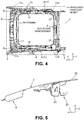
FIG. 4 is a diagram corresponding toFIG. 3 , from which a first roof reinforcement and a roof opening-closing unit are omitted. -
FIG. 5 is a cross-sectional view taken along line V-V inFIG. 3 . -
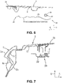
FIG. 6 is a cross-sectional view taken along line VI-VI inFIG. 3 . -
FIG. 7 is a cross-sectional view taken along line VII-VII inFIG. 3 . -
FIG. 8 is a cross-sectional view taken along line VIII-VIII inFIG. 3 . -
FIG. 9 is an enlarged view of front-side principal components inFIG. 3 . -
FIG. 10 is an enlarged view of rear-side principal components inFIG. 3 . -
FIG. 11 is an enlarged view of front-side principal components inFIG. 4 . -
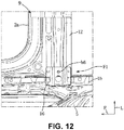
FIG. 12 is an enlarged view of rear-side principal components inFIG. 4 . -
FIG. 13 is a perspective view of a front-side bracket. -
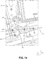
FIG. 14 is a mounted state diagram of the front-side bracket. -
FIG. 15 is a cross-sectional view taken along line XV-XV inFIG. 9 . - An embodiment of the present invention will hereinafter be described in detail based on drawings.
- The following descriptions describe examples where the present invention is applied to an upper vehicle-body structure for a vehicle but do not restrict the present invention, application thereof, or use thereof.
- In the following, a first embodiment of the present invention will be described based on
FIG. 1 to FIG. 15 . - As illustrated in
FIG. 1 and FIG. 2 , a vehicle V is a four-door passenger vehicle including a pair of left and rightroof side rails 1 extending in a front-rear direction, aroof panel 2 placed between the pair ofroof side rails 1, a pair of left and rightfront pillars 3 respectively extending from front end portions of the pair ofroof side rails 1 to a lower front side, a pair of left andright center pillars 4 respectively extending downward from middle portions of the pair ofroof side rails 1, a pair of left and rightrear pillars 5 respectively extending downward from rear end portions of the pair ofroof side rails 1, a roof opening-closing unit 20 in which an opening 2a formed in theroof panel 2 is capable of being opened and closed, and so forth. In the following, descriptions will be made while in the drawings, the direction of an arrow F indicates the front in a vehicle front-rear direction, the direction of an arrow L indicates the left in a vehicle width direction, and the direction of an arrow U indicates the upper side in a vehicle up-down direction. - First, a description will be made about an outline configuration of the vehicle V according to the present invention.
- As illustrated in
FIG. 7 andFIG. 8 , theroof side rail 1 has an outer roof rail 1a, aninner roof rail 1b which forms a closed cross-section extending in the front-rear direction while cooperating with this outer roof rail 1a, and aroof rail reinforcement 1c as a reinforcement member whose upper end portion is held between the outer roof rail 1a and theinner roof rail 1b and which demarcates the closed cross-section of theroof side rail 1 in the vehicle width direction. Both of left and right end portions of theroof panel 2 are joined, by welding, to vehicle-width-direction inner side ends of the pair of outer roof rails 1a. - As illustrated in
FIG. 3 andFIG. 4 , the pair of roof side rails 1 are coupled together in the vehicle width direction by afront header 6 extending in a left-right direction, arear header 7 extending in the left-right direction, and first andsecond roof reinforcements - As illustrated in
FIG. 3 ,FIG. 4 ,FIG. 9 , andFIG. 11 , thefront header 6 has a pair ofheader gussets 6a formed of metal in both of left and right end portions and is connected with the pair ofroof rail inners 1b respectively via the pair ofheader gussets 6a. As illustrated inFIG. 5 , thefront header 6 is formed to have a generally hat-shaped cross-section and forms a generally rectangular closed cross-section extending in the left-right direction while cooperating with a front end portion of theroof panel 2. Similarly to thefront header 6, therear header 7 is formed to have a generally hat-shaped cross-section and forms a closed cross-section extending in the left-right direction while cooperating with a rear end portion of theroof panel 2. - The first and
second roof reinforcements - The
first roof reinforcement 8 is composed of a closed cross-sectional structure made of two iron plate materials. - As illustrated in
FIG. 3 andFIG. 4 , thefirst roof reinforcement 8 is configured to couple the pair of roof side rails 1 together in close positions to connection portions between the roof side rails 1 and thecenter pillars 4, in other words, in a central position of theopening 2a in the front-rear direction. - The
second roof reinforcement 9 is composed of an iron plate-shaped structure. - As illustrated in
FIG. 4 ,FIG. 6 ,FIG. 8 andFIG. 12 , thesecond roof reinforcement 9 is configured to couple the pair of roof side rails 1 together in close positions to connection portions between the roof side rails 1 and therear pillars 5, in other words, in a back end position of theopening 2a in the front-rear direction. Thissecond roof reinforcement 9 has a pair ofrear fixing plates 12 in both of left and right end portions and is connected with the pair ofroof rail inners 1b via the pair ofrear fixing plates 12. - The
rear fixing plate 12 formed of iron is formed into a general L-shape in a planar view. - The
rear fixing plates 12 reinforce an outer edge portion of theopening 2a from a back surface of theroof panel 2 while cooperating with afront fixing plate 11 formed of iron and a pair of left and rightside fixing plates 13. Thefront fixing plate 11 is formed into a general U-shape in a planar view and is connected with thefront header 6. Theside fixing plate 13 is formed into a general I-shape in a planar view and is connected with the roof rail inner 1b. Those fixingplates 11 to 13 configure reinforcement members for mounting the roof opening-closing unit 20. - As illustrated in
FIG. 4 , in theroof panel 2, theopening 2a in a general rectangular shape in a planar view is formed from a close position to thefront header 6 to the close positions to the connection portions between the roof side rails 1 and therear pillars 5. The outer edge portion of thisopening 2a is surrounded by a vehicle-body framework member F1. - In the present embodiment, the pair of roof side rails 1, the
front header 6, and thesecond roof reinforcement 9 correspond to the vehicle-body framework member F1. This vehicle-body framework member F1 has a pair of left and right front-side vehicle-body corner portions C1a composed of the pair of roof side rails 1 and thefront header 6 and a pair of left and right rear-side vehicle-body corner portions C1b composed of the pair of roof side rails 1 and the second roof reinforcement 9 (the rear fixing plates 12). - The
front pillar 3 extends from an upper end portion of a hinge pillar (not illustrated) to an upper rear side and is coupled with theroof side rail 1 and theheader gusset 6a. Thisfront pillar 3 forms a closed cross-section by an outer panel and an inner panel and has a pillar reinforcement for reinforcement in this closed cross-section (all not illustrated). Thecenter pillar 4 extends upward from a side sill and is coupled with theroof side rail 1. Thiscenter pillar 4 forms a closed cross-section by an outer panel and an inner panel and has apillar reinforcement 4c for reinforcement to be coupled with theroof rail reinforcement 1c in this closed cross-section (seeFIG. 7 ). Therear pillar 5 extends upward from the side sill and is coupled with theroof side rail 1. Thisrear pillar 5 forms a closed cross-section by an outer panel and an inner panel and has apillar reinforcement 5c for reinforcement to be coupled with theroof rail reinforcement 1c in this closed cross-section (seeFIG. 8 ). - Next, the roof opening-
closing unit 20 will be described. - The roof opening-
closing unit 20 has a tilting-up mechanism (not illustrated) which changes a posture of a front-half portion of a transparent glass panel 21 (cover member) into a shape inclined upward toward the rear and operates theglass panel 21 to partially open, an opening mechanism (not illustrated) which causes the front-half portion of theglass panel 21 to overlap with a rear-half portion and operates theglass panel 21 to fully open, and a sunshade mechanism which blocks sunlight transmitted through theglass panel 21. - As illustrated in
FIG. 1 to FIG. 3 , the roof opening-closing unit 20 has, as main configuration elements, theglass panel 21 composed of the front-half portion and the rear-half portion, a pair of left and right side frames 22, a front-side member 23 coupling front end portions of the pair of side frames 22 together in the vehicle width direction, ashade device 30 coupling rear end portions of the pair of side frames 22 together in the vehicle width direction, and so forth. - As illustrated in
FIG. 7 , theside frame 22 is configured to have a generally U-shaped cross-section. Thisside frame 22 is formed of an aluminum alloy material by extrusion. - As illustrated in
FIG. 5 , the front-side member 23 is configured to have a generally U-shaped cross-section. This front-side member 23 is molded by using a synthetic resin material. - As illustrated in
FIG. 6 , theshade device 30 is formed into a generally rectangular cuboid shape with a sheet-shapedshade 31 covering a lower surface of theglass panel 21, a roll-screen shade portion 32 winding thisshade 31 in a drawable manner, anaccommodation portion 33 which is formed of iron and accommodates theshade 31 and the roll-screen shade portion 32. A bottom plate portion of theaccommodation portion 33 bears theshade 31 and the roll-screen shade portion 32 from a lower side. - As illustrated in
FIG. 3 , the roof opening-closing unit 20 secures rigidity by a unit framework member F2. In the present embodiment, the pair of side frames 22, the front-side member 23, and theshade device 30 correspond to the unit framework member F2. This unit framework member F2 has a pair of left and right front-side unit corner portions C2a composed of the pair of side frames 22 and the front-side member 23 and a pair of left and right rear-side unit corner portions C2b composed of the pair of side frames 22 and theshade device 30. - As illustrated in
FIG. 9 to FIG. 12 , the roof opening-closing unit 20 is mounted on the vehicle-body framework member F1 via a pair of left and right front-side brackets 15 and a pair of left and right rear-side brackets 16. - Specifically, as illustrated in
FIG. 3 andFIG. 4 , close regions to the front-side unit corner portions C2a are fixed to close regions to the front-side vehicle-body corner portions C1a via the front-side brackets 15, and close regions to the rear-side unit corner portions C2b are fixed to close regions to the rear-side vehicle-body corner portions C1b via the rear-side brackets 16. - The front-
side bracket 15 will be described. - As illustrated in
FIG. 13 , the front-side bracket 15 is made of an iron plate material and includes abody portion 15a extending in the front-rear direction and a protrudingportion 15b protruding from a front-side portion of thisbody portion 15a to a vehicle-width-direction inner side. - The
body portion 15a has a pair of bolt holes h1 and h2 aligned in the left-right direction in a front end portion and a pair of bolt holes h3 and h4 aligned in the front-rear direction in a rear-half portion. Thebody portion 15a includes abead 15c formed between the pair of bolt holes h1 and h2 and aflange portion 15f formed in a vehicle-width-direction outer side end. Thebead 15c bulges downward and extends in the front-rear direction. Theflange portion 15f is formed to be bent downward from a front end to a back end of thebody portion 15a. - The protruding
portion 15b has a single bolt hole h5 in a vehicle-width-direction inner side portion. - Bolts b1 to b5 are respectively inserted through the bolt holes h1 to h5.
- As illustrated in
FIG. 14 , the bolt hole h2 is formed on an extension line A connecting the pair of bolt holes h3 and h4 (bolts b3 and b4), and the bolt hole h1 is formed on a vehicle-width-direction outer side of the bolt hole h2. - As illustrated in
FIG. 9 ,FIG. 11 , andFIG. 15 , the front-side bracket 15 is fastened and fixed, from a lower side, to a rear end portion of theheader gusset 6a and a front end portion of the front fixing plate 11 (the close region to the front-side vehicle-body corner portion C1a) via the bolts b1 and b2 inserted through the bolt holes h1 and h2. Thus, theheader gusset 6a and the front fixingplate 11 correspond to a front gusset. - A portion of the front-
side member 23 close to the front-side unit corner portion C2a is fastened and fixed, from a lower side, to the front-side bracket 15 via the bolts b3 to b5 inserted through the bolt holes h3 and h5. - The bolts b3 and b4 fasten the front-
side bracket 15, theside frame 22, and the front-side member 23 together. Here, the bolt holes h1 and h2 correspond to vehicle-body-side fastening points of the front-side bracket 15, and the bolt holes h3 to h5 correspond to unit-side fastening points of the front-side bracket 15. - The rear-
side bracket 16 will be described. - The rear-
side bracket 16 is made of an iron plate material and is formed to have a generally hat-shaped cross-section. - As illustrated in
FIG. 8 ,FIG. 10 , andFIG. 12 , the rear-side bracket 16 is fastened and fixed, from a lower side, to a vehicle-width-direction outer side end of the rear fixing plate 12 (the close region to the rear-side vehicle-body corner portion C1b) via a bolt b6 inserted through a bolt hole h6. - A portion of the accommodation portion 33 (shade device 30) close to the rear-side unit corner portion C2b is fastened and fixed, from a lower side, to the rear-
side bracket 16 via the bolt b6 inserted through the bolt hole h6. - The bolt b6 fastens the
accommodation portion 33 and therear fixing plate 12 together with the rear-side bracket 16 interposed therebetween. Thus, therear fixing plate 12 corresponds to a rear gusset. - Next, a description will be made about actions and effects of an upper vehicle-body structure for the vehicle V according to the embodiment of the present invention.
- In the present embodiment, because the roof opening-
closing unit 20 has the unit framework member F2 which is in a generally rectangular shape in a planar view and in which the corner portions are formed, theglass panel 21 can be set wide, and rigidity of the roof opening-closing unit 20 can be maintained high even when theglass panel 21 has a wide opening. Because portions of the unit framework member F2 close to the unit corner portions C2a and C2b are coupled with portions of the vehicle-body framework member F1 close to the vehicle-body corner portions C1a and C1b, rigidity of the vehicle-body framework member F1 can be reinforced by using the rigidity of the roof opening-closing unit 20, and rhombic deformation of theopening 2a can be inhibited. - A vehicle body has, in a rear part, the pair of left and right
rear pillars 5 extending in an up-down direction, and the portions of the vehicle-body framework member F1 close to the rear-side vehicle-body corner portions C1b are coupled with therear pillars 5. Thus, the portions of the vehicle-body framework member F1 close to the rear-side vehicle-body corner portions C1b can be coupled with therear pillars 5 in addition to the portions close to the rear-side unit corner portions C2b, and rhombic deformation of theopening 2a can further be inhibited. - The vehicle-body framework member F1 includes the pair of left and right roof side rails 1 extending in the front-rear direction, the
front header 6 coupling the front end portions of the pair of roof side rails 1 together in the vehicle width direction, and thesecond roof reinforcement 9 coupling rear-side intermediate portions of the pair of roof side rails 1 together in the vehicle width direction, the unit framework member F2 is coupled with the vehicle-body framework member F1 via the pair of left and right front-side brackets 15 and the pair of left and right rear-side brackets 16, and the front-side bracket 15 is fastened to thefront header 6 at the two bolt holes h1 and h2 aligned in the vehicle width direction. Thus, the portions of the vehicle-body framework member F1 close to the front-side vehicle-body corner portions C1a can be coupled with thefront header 6 in addition to the portions close to the front-side unit corner portions C2a, and rhombic deformation of theopening 2a can further be inhibited. - The front-
side bracket 15 is fastened to the unit framework member F2 at at least two bolt holes h3 and h4 aligned in the front-rear direction, the bolt hole h2 between the bolt holes h1 and h2 is disposed in a close position to the extension line A connecting the two bolt holes h3 and h4, and the bolt hole h1 between the bolt holes h1 and h2 is disposed in a position on the vehicle-width-direction outer side of the extension line A. Thus, the unit framework member F2 is pulled from the vehicle-width-direction outer side, and torsional deformation of the roof opening-closing unit 20 can thereby be inhibited. - The front-
side bracket 15 has thebead 15c extending in the vehicle front-rear direction between the bolt holes h1 and h2 and theflange portion 15f bent in the up-down direction in the vehicle-width-direction outer side end. Thus, displacement of the portion of the unit framework member F2 close to the front-side unit corner portion C2a can be inhibited. - The
front header 6 has theheader gussets 6a which correspond to a pair of left and right front gussets connected with the pair of roof side rails 1 in both end side portions in the vehicle width direction, thesecond roof reinforcement 9 has therear fixing plates 12 which correspond to a pair of left and right rear gussets connected with the pair of roof side rails 1 in both end side portions in the vehicle width direction, theheader gusset 6a corresponds to the portion close to the front-side vehicle-body corner portion C1a, and therear fixing plate 12 corresponds to the portion close to the rear-side vehicle-body corner portion C1b. Accordingly, the unit framework member F2 and the vehicle-body framework member F1 can be coupled together via theheader gussets 6a and therear fixing plates 12. - The unit framework member F2 includes the pair of left and right side frames 22 extending in the front-rear direction, the front-
side member 23 coupling the front end portions of the pair of side frames 22 together in the vehicle width direction, and the accommodation portion 33 (shade device 30) coupling the rear end portions of the pair of side frames 22 together in the vehicle width direction, a connecting portion between the front-side member 23 and theside frame 22 corresponds to the portion close to the front-side unit corner portion C2a, and a vehicle-width-direction outer-side portion of theaccommodation portion 33 corresponds to the portion close to the rear-side unit corner portion C2b. Accordingly, the unit framework member F2 and the vehicle-body framework member F1 can be coupled together via connecting portions between the front-side member 23 and the side frames 22 and vehicle-width-direction outer-side portions of theaccommodation portion 33. - Next, a description will be made about modifications in which the above embodiment is partially changed.
- 1] In the above embodiment, an example is described where the unit framework member F2 is composed of the pair of side frames 22, the front-
side member 23, and theshade device 30; however, theshade device 30 does not necessarily have to be included, but the unit framework member F2 may be composed of a pair of side frames, a front-side member coupling front end portions of the pair of side frames together, and a rear-side member which couples rear end portions of the pair of side frames together and does not have a shade device function. - 2] In the above embodiment, an example is described where the roof opening-
closing unit 20 has the tilting-up mechanism, which changes the posture of the front-half portion of thetransparent glass panel 21 into a shape inclined upward toward the rear and operates theglass panel 21 to partially open, and an opening mechanism, which causes the front-half portion of theglass panel 21 to overlap with the rear-half portion and operates theglass panel 21 to fully open; however, the tilting-up mechanism does not necessarily have to be included, but a roof opening-closing unit may include only the opening mechanism which operates theglass panel 21 to fully open. - 3] Other than those, a person skilled in the art would be capable of realizing forms in which various changes are added to the above embodiment or forms in which embodiments are combined together without departing from the gist of the present invention, and the present invention encompasses such changed forms.
-
- 1
- roof side rail
- 2
- roof panel
- 2a
- opening
- 3
- front pillar
- 5
- rear pillar
- 6
- front header
- 6a
- header gusset
- 9
- second roof reinforcement
- 15
- front-side bracket
- 15c
- bead
- 15f
- flange portion
- 16
- rear-side bracket
- 20
- roof opening-closing unit
- 21
- glass panel
- 22
- side frame
- 23
- front-side member
- 30
- shade device
- 33
- accommodation portion
- V
- vehicle
- F1
- vehicle-body framework member
- F2
- unit framework member
Claims (8)
- An upper vehicle-body structure for a vehicle (V), comprising:a roof opening-closing unit (20) which has a cover member (21) being capable of opening and closing a generally rectangular opening (2a) formed in a roof panel (2); anda vehicle-body framework member (F1) which surrounds an outer edge portion of the opening (2a) and in which, in a planar view, corner portions (C1a, C1b) are formed,characterized in thatthe roof opening-closing unit (20) has a unit framework member (F2) which, in a planar view, is in a generally rectangular shape and in which corner portions (C2a, C2b) are formed, andportions of the unit framework member (F2) close to unit framework member corner portions (C2a, C2b) are coupled with portions of the vehicle-body framework member (F1) close to vehicle-body corner portions (C1a, C1b) .
- The upper vehicle-body structure for a vehicle (V) according to claim 1, characterized in that
a vehicle body has a pair of left and right pillars (3) extending in an up-down direction, and
the portions of the vehicle-body framework member (F1) close to the vehicle-body corner portions (C1a, C1b) are coupled with the pillars (3). - The upper vehicle-body structure for a vehicle (V) according to claim 1 or 2, characterized in that
the vehicle-body framework member (F1) includes a pair of left and right roof side rails (1) extending in a vehicle front-rear direction, a front header (6) coupling front end portions of the pair of roof side rails (1) together in a vehicle width direction, and a roof reinforcement (9) coupling rear-side intermediate portions of the pair of roof side rails (1) together in the vehicle width direction,
the unit framework member (F2) is coupled with the vehicle-body framework member (F1) via a pair of left and right front-side brackets (15) and a pair of left and right rear-side brackets (16). - The upper vehicle-body structure for a vehicle according to claim 3, characterized in that
the front-side bracket (15) is fastened to the front header (6) at two vehicle-body-side fastening points (h1, h2) aligned in the vehicle width direction. - The upper vehicle-body structure for a vehicle according to claim 3 or claim 4, characterized in that
the front-side bracket (15) is fastened to the unit framework member (F2) at at least two unit-side fastening points (h3, h4) aligned in the vehicle front-rear direction,
one vehicle-body-side fastening point (h2) of the vehicle-body-side fastening points (h1, h2) is disposed in a close position to an extension line (A) connecting the two unit-side fastening points (h3, h4), and a remaining vehicle-body-side fastening point (h1) of the vehicle-body-side fastening points (h1, h2) is disposed in a position on a vehicle-width-direction outer side of the extension line (A). - The upper vehicle-body structure for a vehicle according to any one of claims 3 to 5, characterized in that
the front-side bracket (15) has a bead (15c) extending in the vehicle front-rear direction between the two vehicle-body-side fastening points (h1, h2) and a flange portion (15f) bent in an up-down direction in a vehicle-width-direction outer side end. - The upper vehicle-body structure for a vehicle according to any one of claims 3 to 6, characterized in that
the front header (6) has a pair of left and right front gussets(6a) connected with the pair of roof side rails (1) in both end side portions in the vehicle width direction,
the roof reinforcement (9) has a pair of left and right rear gussets (12) connected with the pair of roof side rails (1) in both end side portions in the vehicle width direction,
the front gusset (6a) corresponds to the portion close to the vehicle-body corner portion (C1a) on a front side, and the rear gusset (12) corresponds to the portion close to the vehicle-body corner portion (C1b) on a rear side. - The upper vehicle-body structure for a vehicle according to any one of claims 1 to 7, characterized in that
the unit framework member (F2) includes a pair of left and right side frames (22) extending in a vehicle front-rear direction, a front-side member (23) coupling front end portions of the pair of side frames (22) together in a vehicle width direction, and a shade accommodation portion (33) coupling rear end portions of the pair of side frames (22) together in the vehicle width direction,
a connecting portion between the front-side member (23) and the side frame (22) corresponds to the portion close to the unit corner portion (C2a) on a front side, and a vehicle-width-direction outer-side portion of the shade accommodation portion (33) corresponds to the portion close to the unit corner portion (C2b) on a rear side.
Applications Claiming Priority (1)
| Application Number | Priority Date | Filing Date | Title |
|---|---|---|---|
| JP2020114227A JP7415278B2 (en) | 2020-07-01 | 2020-07-01 | Vehicle upper body structure |
Publications (2)
| Publication Number | Publication Date |
|---|---|
| EP3932710A1 true EP3932710A1 (en) | 2022-01-05 |
| EP3932710B1 EP3932710B1 (en) | 2023-09-13 |
Family
ID=76623945
Family Applications (1)
| Application Number | Title | Priority Date | Filing Date |
|---|---|---|---|
| EP21181736.6A Active EP3932710B1 (en) | 2020-07-01 | 2021-06-25 | Upper vehicle-body structure for vehicle |
Country Status (4)
| Country | Link |
|---|---|
| US (1) | US11565758B2 (en) |
| EP (1) | EP3932710B1 (en) |
| JP (1) | JP7415278B2 (en) |
| CN (1) | CN113879404B (en) |
Families Citing this family (1)
| Publication number | Priority date | Publication date | Assignee | Title |
|---|---|---|---|---|
| USD1001702S1 (en) * | 2023-06-20 | 2023-10-17 | Yongfu Li | Sunshade |
Citations (6)
| Publication number | Priority date | Publication date | Assignee | Title |
|---|---|---|---|---|
| US4159144A (en) * | 1977-09-01 | 1979-06-26 | General Motors Corporation | Vehicle body sunroof |
| EP1418076A1 (en) * | 2002-11-07 | 2004-05-12 | Mazda Motor Corporation | Vehicle upper body structure |
| JP2007186207A (en) | 2007-04-17 | 2007-07-26 | Toyota Auto Body Co Ltd | Automobile roof structure |
| US20130119647A1 (en) * | 2011-11-11 | 2013-05-16 | Mazda Motor Corporation | Upper vehicle-body structure of vehicle |
| FR3012769A1 (en) * | 2013-11-07 | 2015-05-08 | Peugeot Citroen Automobiles Sa | AUTOMOTIVE VEHICLE ROOF WITH OPENING AND TRANSPARENT PANEL. |
| DE102015117327A1 (en) * | 2015-10-12 | 2017-04-13 | Webasto SE | Openable vehicle roof with fixed roof element |
Family Cites Families (5)
| Publication number | Priority date | Publication date | Assignee | Title |
|---|---|---|---|---|
| JPH085319B2 (en) * | 1989-02-27 | 1996-01-24 | 日産自動車株式会社 | Car sunroof structure |
| JP4284793B2 (en) * | 1999-11-17 | 2009-06-24 | マツダ株式会社 | Upper body structure of the vehicle |
| DE102015005167A1 (en) * | 2015-04-23 | 2016-10-27 | Webasto SE | Vehicle roof module with a roof element and a roller blind device |
| US10173503B2 (en) * | 2015-07-08 | 2019-01-08 | Inalfa Roof Systems Group B.V. | Open roof construction for a vehicle and rollo assembly for use therein |
| JP6348922B2 (en) * | 2016-03-29 | 2018-06-27 | 本田技研工業株式会社 | Roof structure |
-
2020
- 2020-07-01 JP JP2020114227A patent/JP7415278B2/en active Active
-
2021
- 2021-04-23 CN CN202110442086.3A patent/CN113879404B/en active Active
- 2021-06-25 EP EP21181736.6A patent/EP3932710B1/en active Active
- 2021-06-25 US US17/358,034 patent/US11565758B2/en active Active
Patent Citations (6)
| Publication number | Priority date | Publication date | Assignee | Title |
|---|---|---|---|---|
| US4159144A (en) * | 1977-09-01 | 1979-06-26 | General Motors Corporation | Vehicle body sunroof |
| EP1418076A1 (en) * | 2002-11-07 | 2004-05-12 | Mazda Motor Corporation | Vehicle upper body structure |
| JP2007186207A (en) | 2007-04-17 | 2007-07-26 | Toyota Auto Body Co Ltd | Automobile roof structure |
| US20130119647A1 (en) * | 2011-11-11 | 2013-05-16 | Mazda Motor Corporation | Upper vehicle-body structure of vehicle |
| FR3012769A1 (en) * | 2013-11-07 | 2015-05-08 | Peugeot Citroen Automobiles Sa | AUTOMOTIVE VEHICLE ROOF WITH OPENING AND TRANSPARENT PANEL. |
| DE102015117327A1 (en) * | 2015-10-12 | 2017-04-13 | Webasto SE | Openable vehicle roof with fixed roof element |
Also Published As
| Publication number | Publication date |
|---|---|
| US11565758B2 (en) | 2023-01-31 |
| JP2022012411A (en) | 2022-01-17 |
| CN113879404A (en) | 2022-01-04 |
| CN113879404B (en) | 2024-07-09 |
| JP7415278B2 (en) | 2024-01-17 |
| EP3932710B1 (en) | 2023-09-13 |
| US20220001934A1 (en) | 2022-01-06 |
Similar Documents
| Publication | Publication Date | Title |
|---|---|---|
| JP4259094B2 (en) | Upper body structure of the vehicle | |
| US7306279B2 (en) | Vehicle rear door and method of assembling same | |
| KR100520595B1 (en) | Vehicle Door | |
| JPH01182120A (en) | Rear opening/closing body structure of automobile | |
| US11548560B2 (en) | Vehicle skeleton structure | |
| CN110228532A (en) | vehicle body structure | |
| CN113246698B (en) | Vehicle doors | |
| CN111791955A (en) | Side body structure of vehicle | |
| CN110228533A (en) | vehicle body structure | |
| JP2001328562A (en) | Rear body structure of vehicle | |
| US11565758B2 (en) | Upper vehicle-body structure for vehicle | |
| JP2003063455A (en) | Front body structure of vehicle | |
| JP2002362419A (en) | Front body structure of vehicle | |
| JP4843643B2 (en) | Car body rear structure | |
| JP3305225B2 (en) | Reinforcement structure for the back door opening of automobiles | |
| JP6194901B2 (en) | Car door structure | |
| EP3785957B1 (en) | Side vehicle-body structure for vehicle, vehicle body structure, and vehicle | |
| JP2002362414A (en) | Side body structure of vehicle | |
| US12202546B2 (en) | Vehicle rear structure | |
| JP7415279B2 (en) | Vehicle upper body structure | |
| JP3179880B2 (en) | Lower body structure of car | |
| JP2006069397A (en) | Vehicle door module structure | |
| JPH08175Y2 (en) | Mounting structure for guide rail with center frame in automobile sliding roof equipment | |
| JP4341289B2 (en) | Sunroof car side body structure | |
| JP2005239075A (en) | Vehicle side door structure |
Legal Events
| Date | Code | Title | Description |
|---|---|---|---|
| PUAI | Public reference made under article 153(3) epc to a published international application that has entered the european phase |
Free format text: ORIGINAL CODE: 0009012 |
|
| STAA | Information on the status of an ep patent application or granted ep patent |
Free format text: STATUS: THE APPLICATION HAS BEEN PUBLISHED |
|
| AK | Designated contracting states |
Kind code of ref document: A1 Designated state(s): AL AT BE BG CH CY CZ DE DK EE ES FI FR GB GR HR HU IE IS IT LI LT LU LV MC MK MT NL NO PL PT RO RS SE SI SK SM TR |
|
| B565 | Issuance of search results under rule 164(2) epc |
Effective date: 20211029 |
|
| STAA | Information on the status of an ep patent application or granted ep patent |
Free format text: STATUS: REQUEST FOR EXAMINATION WAS MADE |
|
| 17P | Request for examination filed |
Effective date: 20220623 |
|
| RBV | Designated contracting states (corrected) |
Designated state(s): AL AT BE BG CH CY CZ DE DK EE ES FI FR GB GR HR HU IE IS IT LI LT LU LV MC MK MT NL NO PL PT RO RS SE SI SK SM TR |
|
| GRAP | Despatch of communication of intention to grant a patent |
Free format text: ORIGINAL CODE: EPIDOSNIGR1 |
|
| STAA | Information on the status of an ep patent application or granted ep patent |
Free format text: STATUS: GRANT OF PATENT IS INTENDED |
|
| RIC1 | Information provided on ipc code assigned before grant |
Ipc: B62D 25/06 20060101ALI20230321BHEP Ipc: B60J 7/02 20060101AFI20230321BHEP |
|
| INTG | Intention to grant announced |
Effective date: 20230425 |
|
| GRAS | Grant fee paid |
Free format text: ORIGINAL CODE: EPIDOSNIGR3 |
|
| GRAA | (expected) grant |
Free format text: ORIGINAL CODE: 0009210 |
|
| STAA | Information on the status of an ep patent application or granted ep patent |
Free format text: STATUS: THE PATENT HAS BEEN GRANTED |
|
| AK | Designated contracting states |
Kind code of ref document: B1 Designated state(s): AL AT BE BG CH CY CZ DE DK EE ES FI FR GB GR HR HU IE IS IT LI LT LU LV MC MK MT NL NO PL PT RO RS SE SI SK SM TR |
|
| REG | Reference to a national code |
Ref country code: CH Ref legal event code: EP |
|
| REG | Reference to a national code |
Ref country code: DE Ref legal event code: R096 Ref document number: 602021005086 Country of ref document: DE |
|
| REG | Reference to a national code |
Ref country code: IE Ref legal event code: FG4D |
|
| REG | Reference to a national code |
Ref country code: LT Ref legal event code: MG9D |
|
| REG | Reference to a national code |
Ref country code: NL Ref legal event code: MP Effective date: 20230913 |
|
| PG25 | Lapsed in a contracting state [announced via postgrant information from national office to epo] |
Ref country code: GR Free format text: LAPSE BECAUSE OF FAILURE TO SUBMIT A TRANSLATION OF THE DESCRIPTION OR TO PAY THE FEE WITHIN THE PRESCRIBED TIME-LIMIT Effective date: 20231214 |
|
| PG25 | Lapsed in a contracting state [announced via postgrant information from national office to epo] |
Ref country code: SE Free format text: LAPSE BECAUSE OF FAILURE TO SUBMIT A TRANSLATION OF THE DESCRIPTION OR TO PAY THE FEE WITHIN THE PRESCRIBED TIME-LIMIT Effective date: 20230913 Ref country code: RS Free format text: LAPSE BECAUSE OF FAILURE TO SUBMIT A TRANSLATION OF THE DESCRIPTION OR TO PAY THE FEE WITHIN THE PRESCRIBED TIME-LIMIT Effective date: 20230913 Ref country code: NO Free format text: LAPSE BECAUSE OF FAILURE TO SUBMIT A TRANSLATION OF THE DESCRIPTION OR TO PAY THE FEE WITHIN THE PRESCRIBED TIME-LIMIT Effective date: 20231213 Ref country code: LV Free format text: LAPSE BECAUSE OF FAILURE TO SUBMIT A TRANSLATION OF THE DESCRIPTION OR TO PAY THE FEE WITHIN THE PRESCRIBED TIME-LIMIT Effective date: 20230913 Ref country code: LT Free format text: LAPSE BECAUSE OF FAILURE TO SUBMIT A TRANSLATION OF THE DESCRIPTION OR TO PAY THE FEE WITHIN THE PRESCRIBED TIME-LIMIT Effective date: 20230913 Ref country code: HR Free format text: LAPSE BECAUSE OF FAILURE TO SUBMIT A TRANSLATION OF THE DESCRIPTION OR TO PAY THE FEE WITHIN THE PRESCRIBED TIME-LIMIT Effective date: 20230913 Ref country code: GR Free format text: LAPSE BECAUSE OF FAILURE TO SUBMIT A TRANSLATION OF THE DESCRIPTION OR TO PAY THE FEE WITHIN THE PRESCRIBED TIME-LIMIT Effective date: 20231214 Ref country code: FI Free format text: LAPSE BECAUSE OF FAILURE TO SUBMIT A TRANSLATION OF THE DESCRIPTION OR TO PAY THE FEE WITHIN THE PRESCRIBED TIME-LIMIT Effective date: 20230913 |
|
| REG | Reference to a national code |
Ref country code: AT Ref legal event code: MK05 Ref document number: 1610922 Country of ref document: AT Kind code of ref document: T Effective date: 20230913 |
|
| PG25 | Lapsed in a contracting state [announced via postgrant information from national office to epo] |
Ref country code: NL Free format text: LAPSE BECAUSE OF FAILURE TO SUBMIT A TRANSLATION OF THE DESCRIPTION OR TO PAY THE FEE WITHIN THE PRESCRIBED TIME-LIMIT Effective date: 20230913 |
|
| PG25 | Lapsed in a contracting state [announced via postgrant information from national office to epo] |
Ref country code: IS Free format text: LAPSE BECAUSE OF FAILURE TO SUBMIT A TRANSLATION OF THE DESCRIPTION OR TO PAY THE FEE WITHIN THE PRESCRIBED TIME-LIMIT Effective date: 20240113 |
|
| PG25 | Lapsed in a contracting state [announced via postgrant information from national office to epo] |
Ref country code: AT Free format text: LAPSE BECAUSE OF FAILURE TO SUBMIT A TRANSLATION OF THE DESCRIPTION OR TO PAY THE FEE WITHIN THE PRESCRIBED TIME-LIMIT Effective date: 20230913 |
|
| PG25 | Lapsed in a contracting state [announced via postgrant information from national office to epo] |
Ref country code: ES Free format text: LAPSE BECAUSE OF FAILURE TO SUBMIT A TRANSLATION OF THE DESCRIPTION OR TO PAY THE FEE WITHIN THE PRESCRIBED TIME-LIMIT Effective date: 20230913 |
|
| PG25 | Lapsed in a contracting state [announced via postgrant information from national office to epo] |
Ref country code: SM Free format text: LAPSE BECAUSE OF FAILURE TO SUBMIT A TRANSLATION OF THE DESCRIPTION OR TO PAY THE FEE WITHIN THE PRESCRIBED TIME-LIMIT Effective date: 20230913 Ref country code: RO Free format text: LAPSE BECAUSE OF FAILURE TO SUBMIT A TRANSLATION OF THE DESCRIPTION OR TO PAY THE FEE WITHIN THE PRESCRIBED TIME-LIMIT Effective date: 20230913 Ref country code: IS Free format text: LAPSE BECAUSE OF FAILURE TO SUBMIT A TRANSLATION OF THE DESCRIPTION OR TO PAY THE FEE WITHIN THE PRESCRIBED TIME-LIMIT Effective date: 20240113 Ref country code: ES Free format text: LAPSE BECAUSE OF FAILURE TO SUBMIT A TRANSLATION OF THE DESCRIPTION OR TO PAY THE FEE WITHIN THE PRESCRIBED TIME-LIMIT Effective date: 20230913 Ref country code: EE Free format text: LAPSE BECAUSE OF FAILURE TO SUBMIT A TRANSLATION OF THE DESCRIPTION OR TO PAY THE FEE WITHIN THE PRESCRIBED TIME-LIMIT Effective date: 20230913 Ref country code: CZ Free format text: LAPSE BECAUSE OF FAILURE TO SUBMIT A TRANSLATION OF THE DESCRIPTION OR TO PAY THE FEE WITHIN THE PRESCRIBED TIME-LIMIT Effective date: 20230913 Ref country code: AT Free format text: LAPSE BECAUSE OF FAILURE TO SUBMIT A TRANSLATION OF THE DESCRIPTION OR TO PAY THE FEE WITHIN THE PRESCRIBED TIME-LIMIT Effective date: 20230913 Ref country code: PT Free format text: LAPSE BECAUSE OF FAILURE TO SUBMIT A TRANSLATION OF THE DESCRIPTION OR TO PAY THE FEE WITHIN THE PRESCRIBED TIME-LIMIT Effective date: 20240115 Ref country code: SK Free format text: LAPSE BECAUSE OF FAILURE TO SUBMIT A TRANSLATION OF THE DESCRIPTION OR TO PAY THE FEE WITHIN THE PRESCRIBED TIME-LIMIT Effective date: 20230913 |
|
| PG25 | Lapsed in a contracting state [announced via postgrant information from national office to epo] |
Ref country code: PL Free format text: LAPSE BECAUSE OF FAILURE TO SUBMIT A TRANSLATION OF THE DESCRIPTION OR TO PAY THE FEE WITHIN THE PRESCRIBED TIME-LIMIT Effective date: 20230913 Ref country code: IT Free format text: LAPSE BECAUSE OF FAILURE TO SUBMIT A TRANSLATION OF THE DESCRIPTION OR TO PAY THE FEE WITHIN THE PRESCRIBED TIME-LIMIT Effective date: 20230913 |
|
| REG | Reference to a national code |
Ref country code: DE Ref legal event code: R097 Ref document number: 602021005086 Country of ref document: DE |
|
| PG25 | Lapsed in a contracting state [announced via postgrant information from national office to epo] |
Ref country code: DK Free format text: LAPSE BECAUSE OF FAILURE TO SUBMIT A TRANSLATION OF THE DESCRIPTION OR TO PAY THE FEE WITHIN THE PRESCRIBED TIME-LIMIT Effective date: 20230913 |
|
| PLBE | No opposition filed within time limit |
Free format text: ORIGINAL CODE: 0009261 |
|
| STAA | Information on the status of an ep patent application or granted ep patent |
Free format text: STATUS: NO OPPOSITION FILED WITHIN TIME LIMIT |
|
| PG25 | Lapsed in a contracting state [announced via postgrant information from national office to epo] |
Ref country code: DK Free format text: LAPSE BECAUSE OF FAILURE TO SUBMIT A TRANSLATION OF THE DESCRIPTION OR TO PAY THE FEE WITHIN THE PRESCRIBED TIME-LIMIT Effective date: 20230913 |
|
| 26N | No opposition filed |
Effective date: 20240614 |
|
| PG25 | Lapsed in a contracting state [announced via postgrant information from national office to epo] |
Ref country code: SI Free format text: LAPSE BECAUSE OF FAILURE TO SUBMIT A TRANSLATION OF THE DESCRIPTION OR TO PAY THE FEE WITHIN THE PRESCRIBED TIME-LIMIT Effective date: 20230913 |
|
| PG25 | Lapsed in a contracting state [announced via postgrant information from national office to epo] |
Ref country code: SI Free format text: LAPSE BECAUSE OF FAILURE TO SUBMIT A TRANSLATION OF THE DESCRIPTION OR TO PAY THE FEE WITHIN THE PRESCRIBED TIME-LIMIT Effective date: 20230913 |
|
| PG25 | Lapsed in a contracting state [announced via postgrant information from national office to epo] |
Ref country code: BG Free format text: LAPSE BECAUSE OF FAILURE TO SUBMIT A TRANSLATION OF THE DESCRIPTION OR TO PAY THE FEE WITHIN THE PRESCRIBED TIME-LIMIT Effective date: 20230913 |
|
| PG25 | Lapsed in a contracting state [announced via postgrant information from national office to epo] |
Ref country code: BG Free format text: LAPSE BECAUSE OF FAILURE TO SUBMIT A TRANSLATION OF THE DESCRIPTION OR TO PAY THE FEE WITHIN THE PRESCRIBED TIME-LIMIT Effective date: 20230913 |
|
| PG25 | Lapsed in a contracting state [announced via postgrant information from national office to epo] |
Ref country code: MC Free format text: LAPSE BECAUSE OF FAILURE TO SUBMIT A TRANSLATION OF THE DESCRIPTION OR TO PAY THE FEE WITHIN THE PRESCRIBED TIME-LIMIT Effective date: 20230913 |
|
| REG | Reference to a national code |
Ref country code: CH Ref legal event code: PL |
|
| PG25 | Lapsed in a contracting state [announced via postgrant information from national office to epo] |
Ref country code: LU Free format text: LAPSE BECAUSE OF NON-PAYMENT OF DUE FEES Effective date: 20240625 |
|
| PG25 | Lapsed in a contracting state [announced via postgrant information from national office to epo] |
Ref country code: IE Free format text: LAPSE BECAUSE OF NON-PAYMENT OF DUE FEES Effective date: 20240625 |
|
| PG25 | Lapsed in a contracting state [announced via postgrant information from national office to epo] |
Ref country code: BE Free format text: LAPSE BECAUSE OF NON-PAYMENT OF DUE FEES Effective date: 20240630 Ref country code: CH Free format text: LAPSE BECAUSE OF NON-PAYMENT OF DUE FEES Effective date: 20240630 |
|
| PG25 | Lapsed in a contracting state [announced via postgrant information from national office to epo] |
Ref country code: FR Free format text: LAPSE BECAUSE OF NON-PAYMENT OF DUE FEES Effective date: 20240630 |
|
| REG | Reference to a national code |
Ref country code: BE Ref legal event code: MM Effective date: 20240630 |
|
| PGFP | Annual fee paid to national office [announced via postgrant information from national office to epo] |
Ref country code: DE Payment date: 20250429 Year of fee payment: 5 |
|
| PG25 | Lapsed in a contracting state [announced via postgrant information from national office to epo] |
Ref country code: CY Free format text: LAPSE BECAUSE OF FAILURE TO SUBMIT A TRANSLATION OF THE DESCRIPTION OR TO PAY THE FEE WITHIN THE PRESCRIBED TIME-LIMIT; INVALID AB INITIO Effective date: 20210625 |
|
| GBPC | Gb: european patent ceased through non-payment of renewal fee |
Effective date: 20250625 |
|
| PG25 | Lapsed in a contracting state [announced via postgrant information from national office to epo] |
Ref country code: HU Free format text: LAPSE BECAUSE OF FAILURE TO SUBMIT A TRANSLATION OF THE DESCRIPTION OR TO PAY THE FEE WITHIN THE PRESCRIBED TIME-LIMIT; INVALID AB INITIO Effective date: 20210625 |
|
| PG25 | Lapsed in a contracting state [announced via postgrant information from national office to epo] |
Ref country code: GB Free format text: LAPSE BECAUSE OF NON-PAYMENT OF DUE FEES Effective date: 20250625 |