EP3932020B1 - Procédé de routage de télégrammes dans un réseau d'automatisation, structure de données, réseau d'automatisation et répartiteur de réseau - Google Patents
Procédé de routage de télégrammes dans un réseau d'automatisation, structure de données, réseau d'automatisation et répartiteur de réseau Download PDFInfo
- Publication number
- EP3932020B1 EP3932020B1 EP20712546.9A EP20712546A EP3932020B1 EP 3932020 B1 EP3932020 B1 EP 3932020B1 EP 20712546 A EP20712546 A EP 20712546A EP 3932020 B1 EP3932020 B1 EP 3932020B1
- Authority
- EP
- European Patent Office
- Prior art keywords
- network
- telegram
- port
- distributor
- data
- Prior art date
- Legal status (The legal status is an assumption and is not a legal conclusion. Google has not performed a legal analysis and makes no representation as to the accuracy of the status listed.)
- Active
Links
- 238000000034 method Methods 0.000 title claims description 67
- 238000012545 processing Methods 0.000 claims description 64
- 238000013467 fragmentation Methods 0.000 claims description 44
- 238000006062 fragmentation reaction Methods 0.000 claims description 44
- 238000009482 thermal adhesion granulation Methods 0.000 description 99
- 230000005540 biological transmission Effects 0.000 description 77
- 239000012634 fragment Substances 0.000 description 29
- 238000004891 communication Methods 0.000 description 17
- 101000597183 Homo sapiens Telomere length regulation protein TEL2 homolog Proteins 0.000 description 5
- 101001057127 Homo sapiens Transcription factor ETV7 Proteins 0.000 description 5
- 102100027263 Transcription factor ETV7 Human genes 0.000 description 5
- 230000000903 blocking effect Effects 0.000 description 4
- 238000006243 chemical reaction Methods 0.000 description 4
- 230000006870 function Effects 0.000 description 4
- 101000785063 Homo sapiens Serine-protein kinase ATM Proteins 0.000 description 2
- 102100039580 Transcription factor ETV6 Human genes 0.000 description 2
- 238000012546 transfer Methods 0.000 description 2
- 230000015572 biosynthetic process Effects 0.000 description 1
- 125000004122 cyclic group Chemical group 0.000 description 1
- 230000001419 dependent effect Effects 0.000 description 1
- 238000011161 development Methods 0.000 description 1
- 230000018109 developmental process Effects 0.000 description 1
- 238000005516 engineering process Methods 0.000 description 1
- 239000000945 filler Substances 0.000 description 1
- 238000002372 labelling Methods 0.000 description 1
- 238000012986 modification Methods 0.000 description 1
- 230000004048 modification Effects 0.000 description 1
- 238000012544 monitoring process Methods 0.000 description 1
Images

Classifications
-
- H—ELECTRICITY
- H04—ELECTRIC COMMUNICATION TECHNIQUE
- H04L—TRANSMISSION OF DIGITAL INFORMATION, e.g. TELEGRAPHIC COMMUNICATION
- H04L12/00—Data switching networks
- H04L12/28—Data switching networks characterised by path configuration, e.g. LAN [Local Area Networks] or WAN [Wide Area Networks]
- H04L12/46—Interconnection of networks
- H04L12/4604—LAN interconnection over a backbone network, e.g. Internet, Frame Relay
- H04L12/462—LAN interconnection over a bridge based backbone
-
- H—ELECTRICITY
- H04—ELECTRIC COMMUNICATION TECHNIQUE
- H04L—TRANSMISSION OF DIGITAL INFORMATION, e.g. TELEGRAPHIC COMMUNICATION
- H04L45/00—Routing or path finding of packets in data switching networks
- H04L45/02—Topology update or discovery
- H04L45/04—Interdomain routing, e.g. hierarchical routing
-
- H—ELECTRICITY
- H04—ELECTRIC COMMUNICATION TECHNIQUE
- H04L—TRANSMISSION OF DIGITAL INFORMATION, e.g. TELEGRAPHIC COMMUNICATION
- H04L12/00—Data switching networks
- H04L12/28—Data switching networks characterised by path configuration, e.g. LAN [Local Area Networks] or WAN [Wide Area Networks]
- H04L12/40—Bus networks
- H04L2012/4026—Bus for use in automation systems
Definitions
- the invention relates to a method for routing telegrams in an automation network.
- the invention further relates to a data structure for use in the method.
- the invention relates to an automation network that includes network participants that are connected to one another via a data line network.
- the invention relates to a network distributor in the automation network, which is designed to carry out the method for routing telegrams.
- Automation networks are often operated as "fieldbus systems". These are industrial bus systems that enable real-time capable control of the machines or systems in the automation network, with the machines or systems in the automation network being controlled using programmable logic controllers (PLC).
- PLC programmable logic controllers
- the PLC uses the fieldbus system to communicate between the field devices, for example sensors and actuators of the machines or systems in the automation network, with the PLC. If several network participants send telegrams via the same data line in the automation network, which can be in the form of a wired or wireless bus system, there must be a way for the network participants to be able to share the same data line for data transmission.
- Fieldbus systems usually work in what is known as "master-slave operation". This means that at least one network participant is designed as a master participant and takes over the control of the processes, while the other network participants, as slave participants, take on the processing of subtasks in the control operation of the automation network.
- the exchange of data takes place in the automation network with the help of telegrams that are issued by the master participant to the slave participants will.
- the slave participants read the output data addressed to them from the telegram and place their input data in the telegram and send the telegram back to the master participant.
- network distributors so-called “switches” are used in automation networks to connect the individual data lines to the connected network participants and to ensure that the data or telegrams are routed via the individual input/output ports of the network distributor network participants connected via the data line network reach their destination.
- the telegrams are routed via the network distributor using routing tables. Routing describes the definition of transmission paths for the transmission of telegrams between the network distributors of the automation network.
- the routing tables mentioned have an entry for each combination of sending network participant and receiving network participant, which contains the destination MAC address (MAC: Media Access Control) of the receiving network participant, the sender MAC address of the sending network participant as well as the input/output Port of the network distributor, which is designed as an output port through which the telegram is output, includes.
- MAC Media Access Control
- the exchanged network participant usually has a new sender MAC address. Since this new sender MAC address is not yet stored as an entry in the routing table of the network distributor, the network distributor must first update the routing table through a learning process, i.e. save the sender MAC address in the routing table when a telegram is received from the network participant, so that the exchanged network participant can take part in the data communication.
- the memory requirement for the routing table increases with the size of the automation network.
- the network distributors can also be in the form of so-called "manageable switches", which means that in addition to the basic functions, they can also have control and monitoring functions.
- Telegrams with underlying Ethernet data transmission protocol e.g. the data transmission protocol PROFINET IRT
- VLAN IDs frame IDs
- VLAN Virtual Local Area Network
- VLANs are logical subnets within a network distributor or within the entire physical automation network.
- An identification number, ie a VLAN ID can be assigned to each VLAN or subnetwork.
- the routing table for each combination of sending network node and receiving network node includes an entry with the VLAN ID, the input/output port of the network distributor, which is designed as an input port, and the one -/Output port of the network distributor, which is designed as an output port.
- Such a routing table is configured using LLDP and SNMP protocol (LLDP: Link Layer Discovery Protocol, SNMP: Simple Network Management Protocol).
- the network distributor uses the LLDP protocol to communicate with each network participant connected to each input/output port to determine who is connected. This information is stored in a database that can be accessed by a master participant via the SNMP protocol. This assumes that every network participant supports the LLDP and the SNMP protocol and has a database.
- the network node that is replaced and that also processes the Ethernet data transmission protocol must be set again as to which subnets the replaced network node should communicate with via VLAN IDs.
- EtherCAT network In an automation network in which telegrams are transmitted with the underlying EtherCAT data transmission protocol, hereinafter referred to as EtherCAT network, no routing in the sense explained above to a specific network node is required if the network node is designed as a slave node and is able to process the EtherCAT data transmission protocol . Because in an automation network designed in this way, the telegrams are always routed through all the slave participants in an EtherCAT segment and sent back to the master participant by the last slave participant in the segment. In the EtherCAT network, the telegrams with the underlying EtherCAT data transmission protocol can be routed from the network distributors to the EtherCAT segments will. Such an EtherCAT network is usually only operated with one data transfer rate. In addition, the runtime of the telegram through the EtherCAT network can increase as the size of the EtherCAT network with a large number of slave participants increases.
- a method for routing telegrams in an automation network according to the preamble of new claim 1, and an automation network according to the preamble of new claim 7 are from the document Jasperneite J. et. al: "A proposal for a Generic Real-Time Ethernet System", IEEE Transactions on Industrial Informatics, 2009-05-01, p. 75-78 known. Form other relevant writings for the characterizing part of the claims Jahanzaib Imtiaz et. al.: "A layer-2 multicast forwarding policy for a generic Real-time Ethernet system", Factory Communications Systems, 2010-05-18, p. 53-60 , U.S. 2010/008372 A1 such as U.S. 2015/117177 A1 .
- a data structure according to the preamble of new claim 5 is out Jahanzaib Imtiaz et. al.: "A layer-2 multicast forwarding policy for a generic Real-time Ethernet system", Factory Communications Systems, 2010-05-18, p. 53-60 known.
- Other relevant documents for the characterizing part of the new claim 5 are Jasperneite J. et. al: "A proposal for a Generic Real-Time Ethernet System", IEEE Transactions on Industrial Informatics, 2009-05-01, p. 75-78 , U.S. 2010/008372 A1 such as U.S. 2015/117177 A1 .
- the proposed method can be used to output telegrams with port addresses as identifiers, which are assigned to an end port of the network distributor, based on the assignment of the port address to an end port, directly from the network distributor without a complicated routing method using a complex routing table, via the corresponding end port will.
- the throughput in the telegram transmission can thus be increased in an advantageous manner in comparison to conventional routing methods.
- the port addresses of the end ports of the network distributor are in the form of a continuous series
- the network distributor can advantageously carry out simplified routing on the basis of the port addresses using comparison and/or logical operators.
- the continuous series can be in the form of symbols, numerical values, a combination of symbols and numerical values, etc., for example.
- the network distributor comprises input/output ports which are identified as forwarding ports.
- further network distributors 120, 130, 140 are connected to the forwarding ports via the data line network (200). If the network distributor receives a telegram with an identifier that does not correspond to a port address of an end port of the network distributor, the network distributor routes the telegram via a forwarding port of the network distributor stored in a routing table.
- the entries in the routing table that are relevant for routing are advantageously limited to the port address, which can also be in the form of a destination address (DST), and to the input/output port of the network distributor, which is marked as a forwarding port. Storage space can thus be saved in the routing table due to the efficient use of information. This can advantageously contribute to reducing costs.
- the routing of the telegrams from the network distributor is also possible via VLAN IDs if the telegrams are sent by the master subscriber with a VLAN tag, or via MAC addresses, in which case each segment with network subscribers has a VLAN ID or MAC Receives an address with which the telegrams can be routed from the network distributor to the respective segment.
- the proposed method also does not require a learning process on the part of the network distributor if a network participant is exchanged in a segment. This is because an exchanged network subscriber does not receive a new entry in the routing table of the network distributor, since the network subscriber can only be addressed via the assigned segment in which the exchanged network subscriber is located. Since the port address is unchanged in this case, communication with the network subscriber can take place instantaneously.
- the forwarding port is marked as an end port at the same time.
- the master subscriber is designed to send telegrams, which are blocked for processing by the network subscribers and each have a first value of a data element of a first data field in the telegram, via the data line network. If the network distributor receives a telegram with a port address as an identifier from the master participant, which is intended for an end port of the network distributor and is blocked for processing by the network participants, the network distributor unlocks the telegram with the port address as an identifier and transmits the telegram via the corresponding input/output port, which is assigned to the end port of the port address, to the segment with network participants for processing.
- the first value of the data element is overwritten by the network distributor with a second value of the data element, with the second value of the data element of the first data field in the telegram indicating a release for processing the telegram for the network participants.
- a segment with network participants designed as EtherCAT slave participants can also be connected via the data line network to the input/output port of the network distributor, which is designated as a forwarding port.
- the input/output port marked as forwarding port can also be the end port for the segment with EtherCAT slave participants.
- the network distributor Release the output port of the network distributor, which is marked as an end port, for processing so that the network participants can process the telegram in the corresponding segment.
- the network distributor outputs the telegram to another network distributor via the input/output port designated as a forwarding port via the data line network
- the network distributor usually does not unlock the telegram before it is output, since it is between the network distributor and another network distributor For example, other network participants can be connected via the data line network that could process the telegram.
- the further network distributor would only release the telegram for processing if the telegram, for example based on the port address as identifier of the telegram, is output directly from the further network distributor via an input/output port of the further network distributor designated as an end port associated with the port address.
- the network distributor can also block a telegram from being processed by the network participants if the network distributor receives a telegram released for processing from a preceding network distributor in the automation network that is not directly marked as an end port for any Input/output port of the network distributor connected segment with network participants is determined. In this way, too, the confidentiality of the telegram transmission can be increased with the aid of the method according to the invention.
- the master subscriber sends query telegrams via the data line network to detect the input/output ports of the network distributor.
- the master participant After receiving a query telegram from the network distributor with port information about the input/output ports of the network distributor, the master participant arranges the individual input/output ports of the network distributor, to which segments with network participants are connected and as end Ports are designed, the port address too.
- the proposed method allows the automation network to be configured centrally by the master participant. In this way, the master participant can also set further network distributors in the automation network and assign unique port addresses for the input/output ports, which are marked as end ports, in order to be able to specifically address or address the segments with network participants with telegrams .
- the data structure is in the form of a telegram, the telegram having a header section, a data section and an end section.
- the header includes the port address as an identifier.
- the data portion includes a first data field having a data item having a first or second value.
- the end section includes a checksum field for an integrity check of sent data.
- the data element has the first value if the telegram is blocked for processing by the network participants and the data element has the second value if the telegram is unblocked for processing by the network participants.
- the network distributor can quickly output the telegram directly via the end port of the network distributor assigned to the port address or via the forwarding port of the network distributor via the data line network to other network distributors.
- the master subscriber can indicate a blocking or a release of the processing of the telegram for the network subscribers. If the telegram is assigned directly to an end port of the network distributor due to the port address as identifier, the network distributor can transmit the telegram for the connected Release segment with network participants for processing by the network distributor overwriting the value that indicates the blocking with the other value.
- the first data field with the data element for displaying the blocking/enabling of a telegram for processing can be used variably for different data transmission protocols and is not limited to the real-time capable EtherCAT data transmission protocol, for example.
- the automation network is in the form of an EtherCAT network and the telegram is in the form of an EtherCAT telegram.
- the EtherCAT telegram includes a TAG field in the header, which has a second, third, fourth and fifth data field.
- the second data field of the TAG field includes a TAG protocol identification for identifying the TAG field in the header section of the EtherCAT telegram.
- the third and fourth data fields of the TAG field include the port address of the EtherCAT telegram, designed as an identifier, which has a destination port address and a sender port address.
- the fifth data field includes fragmentation information if the telegram is fragmented.
- the data section includes another header section which has a length field, a reserve field and the first data field.
- the first data field is designed as a type field and the data element is designed as an EtherCAT protocol type. If the EtherCAT telegram is blocked for processing by the network participants, the EtherCAT protocol type has the first value. If the EtherCAT telegram is unlocked for processing by the network participants, the EtherCAT protocol type includes the second value.
- the telegram can advantageously be in the form of an EtherCAT telegram and use the proven real-time capable EtherCAT data transmission protocol, with the further header section of the telegram then being in the form of an EtherCAT telegram header section.
- the EtherCAT protocol type of the type field includes the second value, which by default with the value one (in the representation of the hexadecimal system) indicates the release of the processing of the telegram, i.e. an addressing of the slave nodes of a segment.
- the further value of the protocol type that is to say the first value of the EtherCAT protocol type, which is designed differently from the second value, can consequently be converted to display the blocking of processing of the telegram for the slave participants of a segment.
- the EtherCAT Protocol type of a telegram arranged in the EtherCAT header section of the telegram, so that the network participants can recognize at an early stage that the telegram has been released for processing or that the telegram has been blocked for processing and can begin processing or forwarding to the next network participant without delay. In this way, the throughput of telegram transmission can be increased.
- a network distributor for an automation network is also proposed, the network distributor being designed to carry out a method for routing telegrams.
- the network distributor can comprise a processing unit, which can be implemented in the form of software or hardware, and have a routing unit and a protocol chip.
- the processing unit includes multiple hardware components or hardware modules.
- the protocol chip can preferably be designed as an EtherCAT slave controller and designate the network distributor as a fully-fledged slave participant, so that the network distributor can also be able to process telegrams from the master participant.
- the network distributor can also route the telegrams of the master device via the forwarding ports of the network distributor using the routing unit, which, for example, accesses the routing table stored in the memory unit of the EtherCAT slave controller, or via the end ports of the network distributor output directly.
- the network distributor can be easily integrated into existing automation networks since the network distributor according to the invention is based on proven EtherCAT technology and is compatible with existing EtherCAT networks.
- Automation networks are usually implemented as fieldbus systems in which the network participants are networked with one another via the fieldbus.
- the network participants can be designed as at least one master participant, as at least one network distributor and as a number of network participants or slave participants.
- the network participants mentioned can be designed to exchange data with control units, with real-time-capable data transmission protocols such as the EtherCAT data transmission protocol usually being used for this purpose.
- the automation network can also have network participants that can process other data transmission protocols such as TCP/IP (TCP/IP: Transmission Control Protocol/Internet Protocol), Ethernet, etc. These network participants do not have to be addressed for control tasks.
- this data transfer protocol data can include diagnostic information about the automation network.
- the invention is explained below using the real-time capable EtherCAT data transmission protocol as an example.
- the above-mentioned network participants connected via the data line network in the automation network can be connected to one another via network distributors, so-called “switches” or “branches".
- the network distributors also serve to coordinate the data exchange between the participants in the segments and to direct the telegrams to their destination in good time.
- Known methods for routing the telegrams the network distributors use MAC addresses of the individual network participants or VLAN IDs of the network participants.
- a disadvantage of the method is the fact that instantaneous communication with a replaced network participant is not possible, since a network distributor can usually only store the new MAC address or the new VLAN ID of the replaced network participant in the routing table with the help of a learning process .
- the routing table also requires the associated MAC addresses or VLAN IDs and the input/output ports of the network distributor for each combination of sending and receiving network participants, which are configured as input ports and output ports.
- the core idea of the present invention therefore lies in providing a simplified method for routing telegrams in an automation network, in which the input/output ports of the network distributor are divided into distinguished end ports and forwarding ports, with the end ports Segments with network participants are connected via a data line network and further network distributors can be connected via the data line network to the forwarding ports in addition to network participants.
- Simplified routing can be achieved in that the end ports of the network distributor are assigned unique port addresses, via which the network distributor can assign a telegram with an identifier as a port address to an end port of the network distributor and the network distributor can send such a telegram directly via the corresponding end port to the segment with network participants for which the telegram is intended.
- the routing of the telegrams via the forwarding port or ports of the network distributor can advantageously be based on a subset of the set of port addresses present in the automation network using comparison operators and/or logical operators be restricted.
- the invention is not restricted to the use of the EtherCAT data transmission protocol, even if this represents the preferred data transmission protocol, but can be used in all automation networks in which telegrams are to be routed.
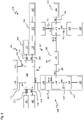
- figure 1 shows a schematic structure of an automation network 100 with network participants 800, which is designed for a method for routing telegrams.
- the automation network 100 includes network participants 800 which are connected to one another via a data line network 200 .
- At least one network participant 800 of the automation network 100 is configured as a master participant 105
- at least one network participant 800 is configured as a network distributor, as in figure 1 shown, for example, as a first to third network distributor 120, 130, 140, and there are also other network participants 800, for example, as another master participant 110 and as first to fourteenth network participants 110, 115, 125, 135, 145, 155, 160, 165, 170, 175, 180, 185, 400, 405, 410 are formed.
- the master subscriber 105 is connected to a first input/output port P0 of a first network distributor 120 via a first data line 205 .
- the first input/output port P0 of the first network distributor 120 can, for example, be identified as an end port of the first network distributor 120, it being possible for a segment with network participants to be connected to an end port. In figure 1 However, only the master subscriber 105 is connected to the first input/output port P0.
- a first port address ID1 i.e.
- first input/output port P0 can be assigned to the first input/output port P0 as a distinguished end port, for example, via which the first network distributor 120 outputs a telegram from the network participants to the master participant 105 which is connected to the first input/output port P0 via the first data line 205.
- the first network distributor 120 can be connected to a further master subscriber 110 via a third input/output port P2 via a third data line 215 .
- the third input/output port P2 of the first network distributor 120 can also be designated as the end port of the first network distributor 120 and can be addressed directly by the first network distributor 120 with a telegram that has a second port address ID2 as an identifier.
- the first network distributor 120 outputs the telegram with the second port address ID2 as an identifier via the third input/output port P2 of the first network distributor 120 identified as the end port via the third data line 215 to the further master subscriber 110 .
- the master participant 105 which is connected to the first input/output port P0 of the first network distributor 120 via the first data line 205, can be designed to carry out a central configuration of the automation network 100 with its network distributors and network participants.
- the first network distributor 120 can be connected to a fourth segment 315 of the automation network 100 via a fourth input/output port P3 of the first network distributor 120 and a fourth data line 220 .
- the fourth segment 315 can include a first network participant 115 .
- the first network participant 115 can be designed, for example, as a coupler element EK1100 from Beckhoff Automation GmbH & Co.
- the first network participant 115 can therefore be designed as a slave participant and process a telegram "on the fly", i.e. read addressed output data and place input data in a telegram and forward the telegram to a subsequent network participant or otherwise send it back to the master participant 105.
- the fourth segment 315 can be embodied as described, for example. In addition, it is conceivable that the fourth segment 315 deviates from the embodiment described and includes further network participants or slave participants, which are not shown.
- the fourth input/output port P3 of the first network distributor 120 is also designated as an end port and is assigned a third port address ID3.
- the first network distributor 120 can therefore output a telegram with the third port address ID3 as an identifier directly via the fourth input/output port P3 of the first network distributor 120 to the fourth segment 315 with the first network subscriber 115 for processing.
- the first network distributor 120 can be connected to a third segment 310 of the automation network 100 via a fifth input/output port P4 of the first network distributor 120 and a fifth data line 225 .
- the fifth input/output port P4 can be designated as an end port and a fourth port address ID4 can have been assigned by the master participant 105 .
- the first network distributor 120 can receive a telegram from the master subscriber 105 with the fourth port address ID4 as an identifier directly via the fifth input/output port P4 of the first network distributor 120 to the third segment 310 with the network participants for processing.
- the third segment 310 can include a second network participant 125, a third network participant 135 and a fourth network participant 145, wherein the second to fourth network participants 125, 135, 145 can each be designed as a slave participant for processing the telegrams from the master participant 105.
- the second network participant 125 can be embodied as a coupler element, for example.
- the third network participant 135 can be embodied, for example, as a simple branch, in which case the simple branch can be designed to also have routing functionality and other protocols, such as the TCP/IP protocol, in addition to the protocol used in the method for data transmission (Transmission Control Protocol/Internet Protocol).
- the fourth network participant 145 can also be embodied as a simple branch, for example.
- the second to fourth network subscribers 125, 135, 145 in the third segment 310 can likewise be designed to implement data communication at a second data transmission rate of 1 Gbit/s or at a second symbol rate of 1 Gbaud.
- the third segment 310 can therefore be operated at the second data transmission rate of 1 Gbit/s instead of at the first data transmission rate of 100 Mbit/s.
- the first and second data transmission rate mentioned above and the data transmission rates mentioned below can also be implemented in deviations from the values explained, such as the second data transmission rate with 2.5 Gbit/s or 5 Gbit/s or 10 Gbit/s, etc..
- no data line with one or more network participants can be connected to a sixth input/output port P5 of the first network distributor 120 .
- no port address is assigned to the sixth input/output port P5, since the sixth input/output port P5 is not marked as an end port of the first network distributor 120.
- the sixth input/output port P5 has been chosen as an example. It is also conceivable that another input/output port of the first network distributor 120 is designed in such a way or that network participants are connected to the sixth input/output port P5 of the first network distributor 120 and the sixth input/output port P5 marked as an end port with an associated port address.
- the first network distributor 120 is connected to a thirteenth network subscriber 405 via a seventh input/output port P6 and a sixth data line 230 .
- the seventh input/output port P6 of the first network distributor 120 can also be identified as an end port and addressed with a ninth port address ID9.
- the first network distributor 120 can output a telegram via the seventh input/output port designated as an end port, analogously to the above description, using the ninth port address ID9 as the identifier of the telegram.
- the thirteenth network participant 405 may not be in the form of a network participant that processes the EtherCAT data transmission protocol, but rather as an Ethernet participant, it being possible for the Ethernet participant to only process telegrams with an underlying Ethernet data transmission protocol.
- the thirteenth network subscriber 405 does not form an independent segment in the automation network.
- the thirteenth network participant 405 is designed to implement the data communication at the second data transmission rate of 1 Gbit/s.
- the first network distributor 120 can be connected to a twelfth network subscriber 400 via an eighth input/output port P7 and a seventh data line 235 .
- the eighth input/output port P7 of the first network distributor 120 can be identified as an end port and addressed with a tenth port address ID10.
- the above description applies analogously to the output of a telegram with the tenth port address ID10 as identifier.
- the twelfth network participant 400 can also be designed to process the Ethernet data transmission protocol and represent an Ethernet participant.
- the Ethernet subscriber can be designed to implement the data communication at the first data transmission rate of 100 Mbit/s.
- the twelfth network participant 400 cannot form an independent segment in the automation network 100 either.
- the first network distributor 120 can be connected to a fifth network subscriber 155 via a second input/output port P1 and a second data line 210 .
- the fifth network participant 155 can be designed for data communication at the second data transmission rate.
- the fifth network participant 155 can be connected to a first input/output port P0 of a second network distributor 130 via the second data line 210 and can be embodied as a slave participant for processing telegrams from the master participant 105 .
- the second network distributor 130 can be connected to a sixth network subscriber 160 via a second input/output port P1 of the second network distributor 130 and via an eighth data line 240 .
- the sixth network participant 160 can also be in the form of the above simple branch and can process telegrams from the master participant 105 .
- the sixth network participant 160 can have a seventh network participant 165 downstream of the eighth data line 240 .
- the seventh network participant 165 can form the last network participant in a first segment 300, which extends from the fifth network participant 155 to the seventh network participant 165, since the network participants in the individual segments are usually arranged in a chain.
- the seventh network participant 165 can be in the form of a coupler element and can be suitable for processing the telegrams from the master participant 105 .
- the second network distributor 130 can be part of the first segment 300 as long as the second input/output port P1 of the second network distributor 130 is set for it. Accordingly, the second input/output port P1 of the first network distributor 120 can be marked as an end port, the end port being the first segment 300 with the fifth network participant 155, the second network distributor 130, the sixth network participant 160 and the seventh network participant 165 can be assigned.
- the first network distributor 120 can send a telegram with an eighth port address ID8 as an identifier, for example directly via the second input/output port P1 of the first network distributor 120, which is marked as an end port, to the fifth network participant 155, which is the first network participant of the first segment 300 forms, spend for processing.
- the first segment 300 beginning with the fifth network participant 155 and comprising the second network distributor 130, the sixth network participant 160 and the seventh network participant 165, can be designed for data communication at the second data transmission rate of 1 g/s, since the fifth network participant 155, the sixth network participant 160 and the seventh network participant 165 are designed in this way, for example.
- the fifth network participant 155, the sixth network participant 160 and the seventh network participant 165 like the first network distributor 120 and the second network distributor 130, are capable of both the second data transmission rate of 1 Gbit/s and the first implement a data transmission rate of 100 Mbit/s.
- the first segment 300 can include other network participants, not shown, which are designed to implement the first data transmission rate.
- the data transmission rate for the participants of the first segment 300 can be set uniformly to the first data transmission rate. This applies equally to the other segments; they too can have additional network participants that are designed to implement only the first data transmission rate. However, this property is not referred to again for the description of the other segments.
- the second network distributor 130 is connected to an eighth network subscriber 170 via a third input/output port P2 and a ninth data line 245 .
- the eighth network participant 170 forms, for example, the first network participant in a second segment 305 and can be provided for processing the telegrams from the master participant 105 as a slave participant.
- the eighth network participant 170 can be designed, for example, for data communication at the second data transmission rate.
- the third input/output port P2 of the second network distributor 130 can be identified as the end port for the second segment 305 and addressed with a seventh port address ID7.
- the eighth network subscriber 170 is also connected to a first input/output port P0 of a third network distributor 140 via the eighth data line 240 .
- the third network distributor 140 can be part of the second segment 305 if a second input/output port P1 of the third network distributor 130 is set for this.
- the third network distributor 140 can be connected to a fourteenth network subscriber 410 via a third input/output port P2 and an eleventh data line 255 .
- the third input/output port P2 of the third network distributor 140 can be a designated end port of the third network distributor 140 and have been assigned a fifth port address ID5 by the master participant 105 .
- the fourteenth network participant 410 is in the form of an Ethernet switch that processes the Ethernet data transmission protocol.
- no independent segment of the automation network 100 can be provided for the fourteenth network participant 410, just as for the twelfth and thirteenth network participants 400, 405, since, for example, only network participants that process the EtherCAT data transmission protocol are intended for this.
- the master participant 105 can assign the third input/output port P2 of the third network distributor 140 the fifth port address Assigned ID5 after the third network distributor 140 has entered port information about the input/output ports of the third network distributor 140, to which segments with network participants are connected, in the query telegram to the master participant 105.
- the master participant 105 can have the fourteenth network participant 410 detected as an Ethernet switch in a next step.
- the example of detecting the fourteenth network subscriber 410 from the master subscriber 105 applies analogously to the twelfth and thirteenth network subscribers 400, 405 and the other network subscribers that are arranged in segments.
- the third network distributor 140 can be connected to an eleventh network participant 185 of a fifth segment 320 of the automation network 100 via a fourth input/output port P3 and a twelfth data line 260 .
- the fourth input/output port P3 of the third network distributor 140 can also be marked as an end port and have been assigned a sixth port address ID6 by the master participant 105 for addressing the fifth segment 320 with the eleventh network participant 185.
- the eleventh network participant 185 be designed to implement the first data transmission rate and to process telegrams from the master subscriber 105.
- the third network distributor 140 can be connected to a ninth network subscriber 175 via a second input/output port P1 of the third network distributor 140 and a tenth data line 250 .
- the ninth network participant 175 can be part of the second segment 305 and designed as a coupler element in order to process telegrams from the master participant 105 as a slave participant.
- the ninth network participant 175 can be designed to implement the second data transmission rate.
- a tenth network participant 180 can be connected to the tenth data line 250, which can also be designed as a slave participant for processing the telegrams from the master participant 105 and can be implemented as a simple branch.
- the tenth network participant 180 can, for example, form the last network participant of the network participants arranged in a chain in the second segment 305 . Consequently, the second input/output port P1 of the third network distributor 140 forms an excellent end port for the second segment 305, which can be addressed with the seventh port address ID7.
- the master participant 105 with a telegram that serves as an identifier has the seventh port address ID7, address the eighth network participant 170, the third network distributor 140, the ninth network participant 175 and the tenth network participant 180 with the telegram.
- the first to third network distributors 120, 130, 140 each include input/output ports that are designated as forwarding ports or implemented as so-called routing ports.
- the second input/output port P1 of the first network distributor 120 in addition to being identified as an end port for the first segment 300, is also identified as a forwarding port.
- the first network distributor 120 can send a telegram with the eighth port address ID8 as an identifier, based on the assignment of the eighth port address ID8 to the second input/output port P1 directly via the second input/output port P1 to the first segment 300 spend.
- the first network distributor 120 can route a telegram from the master subscriber 105, which has the seventh port address ID7 as an identifier, for example, via the second input/output port P1 of the first network distributor 120 designated as a forwarding port.
- the routing from the first network distributor 120 for the telegram can be simplified to a routing decision that can be made using comparison operators and/or logical operators.
- the master subscriber 105 can have stored in the routing table of the first network distributor 120 that the first network distributor 120 telegrams with port addresses that are greater than or equal to the combined symbol and numerical value of the fifth port address ID5 and less than or equal to the combined symbol and numerical value of the eighth port address ID8 are formed, routed via the second input/output port of the first network distributor 120, which is distinguished as a forwarding port.
- the master subscriber 105 can block the telegram with the seventh port address ID7 as an identifier for processing by the network subscribers and display this, for example, with a first value of a data element of a first data field in the telegram or with a first value of an EtherCAT protocol type in the telegram, in order to prevent that the first network distributor 120 and the fifth network participant 155 process the telegram on the way to the second network distributor 130. It is also conceivable that the assignment of the port addresses to the input/output ports of the network distributor marked as end ports is also stored by the master participant 105 in the routing tables of the network distributor.
- the second network distributor 130 can also have an input/output port designated as a forwarding port, which can also be designated as an end port.
- this is, for example, the third input/output port P2 of the second network distributor 130.
- the third input/output port P2 of the second network distributor 130 is the end port for the telegram with the seventh port address ID7 as an identifier, and is also the one -/Output port via which the second network distributor routes 130 telegrams with the fifth and sixth port addresses ID5, ID6 as identifiers.
- the second network distributor 130 can also be stored in the routing table of the second network distributor 130 that the second network distributor routes or spends In addition, it can be stored in the routing table, for example for the telegram with the seventh port address ID7 as an identifier, that the second network distributor 130 sets the first value of the data element or the EtherCAT protocol type of the telegram to the second value or overwrites it with the second value, the the network participants of the second segment 305 indicates a release for processing the telegram before the second network distributor 130 sends the telegram via the third input/output port P2, which in this case corresponds to a designated end port, and via the ninth data line 245 outputs the second segment 305 for the network participants to process.
- the third network distributor 140 can send the telegram back to the master participant 105 via the first input/output port, which is a designated forwarding port, with the master participant 105 being addressable via the first port address ID1 is. Because it can be stored in the routing table of the third network distributor 140 that the third network distributor 140 telegrams with port addresses as identifiers as a combined symbol numerical value greater than or equal to the first port address ID1 and less than or equal to the fourth port address ID4 and greater than or equal to the eighth port address ID8 and less than or equal to outputs or routes the tenth port address ID10 via the first input/output port P0 of the third network distributor 140 .
- the routing table of the second network distributor can also have an entry, similar to the explanation above, so that the second network distributor 130 can send telegrams with port addresses as identifiers as a combined symbol numerical value greater than or equal to the first port address ID1 and less than or equal to the fourth port address ID4 and greater than or equal to the fifth port address ID5 and less than or equal to the seventh port address ID7 can issue or route via the first input/output port P0 as an excellent forwarding port.
- the first network distributor 120 outputs the telegram explained in the example with the first port address ID1 as an identifier directly to the master subscriber 105 via the first input/output port P0.
- FIG 1 three network distributors are shown as an example, the first to third network distributors 120, 130, 140, each with a different number of first to eighth input/output ports P0 to P7.
- the individual network distributors can each have a different number of input/output ports, so that these can generally also be referred to as input/output ports PX, with the X being the index for the numerical value of the respective input/output port. output port.
- the maximum number of PX input/output ports in a single network splitter is not limited to the in figure 1 exemplary shown number of eight input / output ports PX limited.
- the first to tenth port addresses ID1 to ID10 can generally also be referred to as port addresses IDY, with the Y as an index for the numerical value of the described combined symbol numerical value of the individual port addresses.
- the port addresses IDY of the input/output ports PX of the individual network distributors which are marked as end ports, form in figure 1 a consecutive series that the master participant 105 can assign for each network distributor, for example in a clockwise direction.
- the advantage of designing the port addresses IDY as a continuous series or assigning them clockwise is that routing decisions by the network distributors are then simplified and can be made in particular on the basis of comparison operators and/or logical operators.
- the entries in the routing table are also reduced due to the simplified routing via port addresses IDY.
- the port addresses IDY are not assigned the embodiment shown and explained is limited, but can be implemented in a different way.
- routing decisions can be made by the network distributors on the basis of comparison operators and/or logical operators, provided that the MAC addresses or VLAN IDs are also assigned as a continuous series by the master subscriber 105 .
- the automation network 100 shown can be designed as an EtherCAT network and the data transmission between the master participant 105 and the individual additional network participants 800 can take place using the real-time capable EtherCAT data transmission protocol.
- the in figure 1 The first to fifth segments shown represent 300 to 320 EtherCAT segments.
- An EtherCAT network generally includes a data line network 200 with data lines, each of which has an outgoing line and a return line. This is included for clarity figure 1 Not shown.
- a network node 800 in an EtherCAT network is designed to process an unblocked telegram on the outgoing line, i.e. to read the output data of the unblocked frame addressed to the network node 800 and to place the input data of the network node 800 in the unblocked frame.
- the telegrams are sent back in the EtherCAT network via the return line, with the network participants 800 not processing the unlocked telegram via the return line.
- the first network distributor 120 and the second and third network distributors 130, 140 are not limited to the in figure 1
- the network topology shown is limited, but can also be used in networks with different network topologies. Furthermore, they are not limited to an EtherCAT network, but can also be used in other networks in which network distributors are required for routing the telegrams and the network distributors are also to be used for processing the telegrams.
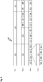
- FIG 2 shows a schematic structure of a data structure 500 for use in the method for data transmission in the in figure 1 illustrated automation network 100 serves.
- the data structure 500 is in the form of a telegram which, for example, is sent by the master participant 105 in figure 1 is output to the network participants in the automation network 100 for processing for the control operation.
- the data structure 500 in figure 2 has a first telegram structure TEL1 and includes a header section 505, a data section 510 and an end section 515.
- the data structure 500 can be designed according to the IEEE standard 802.3 and include the Ethernet data frame format for packet-oriented transmission of the data.
- the data structure has a second telegram structure TEL2.
- the header section 505 of the data structure 500 is then in the form of an Ethernet header section 520 .
- the data section 510 of the data structure 500 then has an EtherCAT header section 525 which includes instructions for the network participants in the automation network 100 .
- the data section 510 includes EtherCAT data, which can be implemented in the form of datagrams.
- the data portion 510 may include a first datagram 530, a second datagram 535, and an nth datagram 540, where the nth datagram 540 indicates that the data structure 500 may comprise any number of datagrams in total.
- no restriction to a specific number of datagrams in the data structure 500 should be made.
- the datagrams themselves each have a control data field and a user data field, which figure 2 is not shown.
- the control data field includes a command field that gives the network participant, which is designed as an EtherCAT slave participant, information about the type of network participant that is to process the user data of the data structure 500 designed as an EtherCAT telegram. For example, whether the network participant should insert data into the user data field of the EtherCAT telegram in a write process, or whether the network participant should first take data from the user data field and then insert some into the user data field in a read/write process, or whether the network participant should only should take data from the user data field in one read process. If a network participant is referred to below, this also includes an EtherCAT slave participant.
- the control data field has an address field. The data area in the network participant with which the network participant is to exchange data when passing through the user data field is specified in the address field.
- the network participant After receiving the control data field in the datagram of the EtherCAT telegram, the network participant starts evaluating the command field and the address field. If the network participant is addressed via the data element for processing the EtherCAT telegram, the network participant takes the output data intended for it from the user data field in the case of a read or read/write datagram while the datagram is in the EtherCAT telegram by the network participant runs through. If it is a write or read/write datagram, the relevant network participant inserts the input data in the user data field in the datagram as it is passed through.
- the padding field 545 is required to bring the EtherCAT telegram in the Ethernet data frame to the required minimum size of the Ethernet data frame of 64 bytes by adding additional bytes added as a pad to the EtherCAT telegram.
- the padding field may be necessary if, for example, less than 46 or 42 bytes (without or with a VLAN TAG corresponding to the IEEE 802.1Q standard) are to be transmitted with the EtherCAT telegram as user data, with a preamble and a start frame delimiter (SFD) field that is in figure 2 are not included and are not counted.
- SFD start frame delimiter
- the checksum field can include, for example, a calculated CRC checksum (CRC: Cyclic Redundancy Check) calculated over the Ethernet data frame, starting with a destination MAC address and ending with the padding field so that the checksum itself is not in the CRC checksum is included.
- CRC checksum Cyclic Redundancy Check
- the CRC checksum is created by the sender and appended to the padding field. After receiving the EtherCAT telegram, the receiver carries out the same CRC checksum calculation, and if the CRC checksum calculated by the receiver does not match the CRC checksum transmitted with the EtherCAT telegram, the receiver assumes that the data transmission was faulty. In such a case, the EtherCAT telegram can be discarded by the recipient.
- a third telegram structure TEL3 in figure 2 shows a more detailed structure of the Ethernet header 520.
- the Ethernet header 520 has a target address field 555, which includes the target MAC address mentioned above, which includes the network participant, which acts as an EtherCAT slave participant, network distributor or as a master participant in the automation network 100 figure 1 can be configured, identified by the EtherCAT telegram is to be received.
- the destination MAC address can also be embodied as a multicast address (addressing of several network participants in the automation network 100) or broadcast address (addressing of all network participants in the automation network 100).
- the Ethernet header 520 has a source address 560 field.
- the sender address field 560 includes a sender address, which is also in the form of a MAC address and identifies the sender.
- the destination address field 555 and the sender address field 560 each comprise 6 bytes.
- the Ethernet header 520 has a TAG field 565 following the sender address field 560 .
- this can be in the form of a VLAN TAG TAG field (VLAN: Virtual Local Area Network) and can comprise 4 bytes.
- the Ethernet header 520 has a protocol 570 field.
- the protocol field 570 can be in the form of a so-called "Ethertype" field and can include a value that specifies a protocol used from a next-higher layer within payload data, with a layer and a next-higher layer based on the OSI model (OSI: Open Systems Interconnection), i.e. the reference model for data transmission protocols in a layered architecture.
- OSI Open Systems Interconnection
- the protocol field 570 has the value 0x88A4 (in the hexadecimal system) if the telegram is in the form of an EtherCAT telegram, since this value is linked to the real-time EtherCAT data transmission protocol.
- the EtherCAT header 525 includes a length field 575.
- the length field 575 provides information about the length of the EtherCAT datagrams.
- the EtherCAT header 525 includes a reserve field 580 in case of need.
- the EtherCAT header 525 comprises a first data field 585, which is embodied as a type field.
- the first data field 585 has the data element with the first or the second value, the data element being in the form of an EtherCAT protocol type.
- the EtherCAT protocol type includes the second value if the segment addressed with the telegram identifier is addressed with network participants for processing.
- the EtherCAT protocol type then has the value 0x1 (in the hexadecimal system) and the network participants in the segment recognize from this value that the EtherCAT telegram is released for processing and start processing the datagrams in the EtherCAT telegram.
- the EtherCAT protocol type has the first value formed differently from the second value with 0x1 (in hexadecimal system), for example the first value can correspond to the value 0x6 (in the hexadecimal system) if the EtherCAT telegram is blocked for processing by the network participants in the respective segment.
- the port address as the identifier of the telegram can be embodied as the MAC address of the destination address field 555, for example.
- the port address as identifier of the telegram can also be in the form of a VLAN ID when using the TAG field 565, which can be designed as a VLAN TAG TAG field.
- the VLAN TAG TAG field can comprise 4 bytes, ie 32 bits, with the first two bytes comprising the value 0x8100 in order to identify the Ethernet data frame as a tagged Ethernet data frame according to the IEEE 802.1Q standard.
- the remaining two bytes include the VLAN ID, fragmentation information if the EtherCAT telegram is fragmented, and a priority with which the EtherCAT telegram can be sent.
- the priority can be in the form of a priority value.
- the individual datagrams in the third telegram structure TEL3 will not be discussed again at this point since they can be designed in the same way as the datagrams in the second telegram structure TEL2.
- the end section 515 can also include a fragmentation field 590 instead of the padding field 545 if the EtherCAT telegram is fragmented by a network distributor.
- the fragmentation field 590 can contain the value zero or have a truth value of zero and thus indicate that the EtherCAT telegram has not been fragmented.
- Bits zero to three of the fragmentation field 590 can include a data frame number, which specifies a value with which the respective Ethernet data frame is identified, with bits zero to three representing the values from one to 15 if the EtherCAT telegram from a network distributor has been fragmented. Bits four through seven of fragmentation field 590 may be provided as spare bits.
- the TAG field 565 can also be structured according to a fourth telegram structure TEL4, where in figure 2 on a representation of the other fields of the Ethernet header 520 shown in the third telegram structure TEL3, as well as the EtherCAT header 525 and the end 515 are not shown. Nevertheless, the fourth telegram structure TEL4 can be in the form of a complete EtherCAT telegram. After the fourth telegram structure TEL4, the TAG field 565 can be in the form of what is known as a “ROUT TAG”, for example, and can differ from a VLAN TAG.
- the TAG field 565 comprising ROUT TAG can have a second data field 595 which is in the form of a TAG protocol identification for identifying the TAG field 565 .
- the second data field 595 can have a value that identifies the Ethernet data frame as a tagged Ethernet data frame according to the IEEE 802.1Q standard, but is designed differently from the identification of the VLAN TAG with the value 0x8100 (in the hexadecimal system).
- the ROUT TAG in the second data field 595 can have a separate identifier in the hexadecimal system.
- the ROUT TAG is identified with the value 0x88A4 (in the hexadecimal system), which is linked to the real-time capable EtherCAT data transmission protocol, and also with another value, a so-called "sub-type".
- the sub-type can have the value 0x7 (in hexadecimal).
- the TAG field 565 may include a third data field 600.
- FIG. the TAG field 565 can have a fourth data field 605 between the third data field 600 and a fifth data field 610 .
- the third data field 600 and the fourth data field 605 can preferably include the port addresses as identifiers of the EtherCAT telegrams.
- the port address as an identifier for an EtherCAT telegram can include, for example, a destination port address (for example, the first port address ID1 as a destination port address for a telegram that is to be sent back to the master device 105), and a sender port address (for example the seventh port address ID7 as the sender port address for a telegram that originates from the network participants of the second segment 305), the third data field 600 being able to have the destination port address and the fourth data field 605 being able to have the sender port address.
- the fifth data field 610 may include an unoccupied area, for example bit zero through bit eleven of the fifth data field 610 may serve as reserve bits.
- the fifth data field 610 can include the fragmentation information, as explained above in connection with the VLAN TAG, in the case of fragmentation of the EtherCAT telegram, and the priority with which the EtherCAT telegram can be sent.
- the EtherCAT telegram can also be embedded in a UDP/IP (UDP: User Datagram Protocol, IP: Internet Protocol) data frame structure, which is figure 2 however, is not shown.
- UDP/IP User Datagram Protocol
- IP Internet Protocol
- the Ethernet header 520 has the destination address field 555 as well as the source address field 560 .
- the Ethernet header 520 includes the protocol field 570, where the protocol field 570 has the value 0x0800 (in hexadecimal) indicating the Internet Protocol (IPv4, Internet Protocol Version 4).
- IPv4 Internet Protocol Version 4
- the EtherCAT header 525, the datagrams and the tail 515 can in that case be embodied analogously to the explanation above, with the end section 515 being able to include the padding field 545 and the checksum field 550 .
- the EtherCAT telegram can also have the TAG field 565, in which case the TAG field 565 can be in the form of a VLAN TAG.
- the TAG field 565 is then arranged analogously to the third telegram structure TEL3. It is also conceivable that the EtherCAT telegram has the ROUT TAG instead of the VLAN TAG.
- FIG 3 shows a schematic fifth and sixth telegram structure TEL5, TEL6 for the data structure 500 in figure 2 , which can be in the form of an EtherCAT telegram.
- the EtherCAT telegram can have the fifth telegram structure TEL5 and the sixth telegram structure TEL6 if the EtherCAT telegram from a network distributor in the in figure 1 automation network 100 shown has been fragmented and a first fragment of the fragmented EtherCAT telegram has, for example, the third and fourth telegram structure TEL3, TEL4.
- a second to nth fragment of the EtherCAT telegram can include the fifth and sixth telegram structure TEL5, TEL6.
- the EtherCAT telegram has a fragment destination address field 615, the fragment destination address field 615 including a seventh data field 625 and an eighth data field 630 according to the sixth telegram structure TEL6.
- the seventh data field 625 of the fragment destination address field 615 can comprise 4 bytes and be designed in the form of a multicast address space, the multicast address space having multicast addresses that are used to address multiple segments with network participants in the in figure 1 illustrated automation network 100 are used.
- the multicast address space can be designed in the form of a unicast address space, the unicast address space having unicast addresses that are used for addressing a single segment with network participants figure 1 serves.
- the multicast address space can also be embodied as a broadcast address space, with the broadcast address space comprising broadcast addresses that are used to address all segments with network participants in figure 1 to serve.
- the seventh data field 625 can comprise the destination MAC address mentioned in connection with the destination address field 555 of the Ethernet header 520 .
- the seventh data field 625 can also have the sender address mentioned in connection with the sender address field 560 of the Ethernet header 520, which can also be in the form of a MAC address.
- the eighth data field 630 of the fragment destination address field 615 may be 2 bytes. Bits zero through three of the eighth data field 630 may include the data frame number, which may indicate the value of the particular Ethernet data frame. Bits four to seven and bit twelve can still be provided as reserve bits and have no occupancy. Bits eight to eleven can include a fragment number that indicates a value of the respective fragment in order to be able to assign the individual fragments to the associated Ethernet data frame. Furthermore, bits thirteen to fifteen can have the priority with which the second to nth fragment of the EtherCAT telegram can be sent, with the priority being in the form of a priority value.
- the data section 510 in the fifth telegram structure TEL5 has been selected as an example and can be used according to the second and third telegram structure TEL2, TEL3 in figure 2 be trained.
- the second to nth fragments of the EtherCAT telegram can include a sixth data field 620, which can have one byte.
- bits zero to three of the sixth data field 620 can be intended to indicate whether another fragment follows or whether the fragment to be transmitted is already the last fragment of the EtherCAT telegram.
- the value zero can indicate that the fragment to be transmitted is the last fragment of the EtherCAT telegram.
- bits four to six can be reserved as reserve bits and bit seven can be used to indicate that the second to nth fragment of the EtherCAT telegram is to be filled with filler bytes, i.e. a padding, if the minimum length is not reached.
- the second byte of the sixth data field 620 can indicate the data frame number, which can indicate the value of the respective Ethernet data frame.
- the second to nth fragment of the EtherCAT telegram can include the checksum field 550 with the checksum calculated over the second to nth fragment, which can be designed analogously to the above explanation.
- the fragment destination address field 615 and the data section 510 of the second to nth fragment of the EtherCAT telegram can together have at least 59 bytes, without the second to nth fragment of the EtherCAT telegram, padding is required in order to achieve the minimum length of the Ethernet frame of 64 bytes.
- the eighth data field 630 can also include its own TAG protocol identification, as explained above in connection with the second data field 595 and the TAG field 565 if the eighth data field 630 instead of a VLAN TAG, for example, as a fragmenter TAG is formed.
- the TAG protocol identification of the The eighth data field 630 may have its own value in hexadecimal.
- the TAG protocol identification includes the value 0x88A4, which is linked to the real-time capable EtherCAT data transmission protocol, and also has another value, the sub-type, which is used, for example, to identify the fragment destination address field 615 can contain the value 0x8 in hexadecimal.
- the structure of the EtherCAT telegram does not necessarily have to contain the order of the network participants in the segments, since the EtherCAT telegrams can address physical memory addresses, hereinafter referred to as physical address range, of the network participants in the segments and on the other hand the EtherCAT telegrams can also be designed as logical telegrams .
- a logical address i.e. a logical address range
- a length of the address range can be specified in the EtherCAT telegram.
- a logical address area can be larger than a physical address area, so that the physical address area can be placed in the logical address area.
- the logical address range can be placed one after the other in the EtherCAT telegram.
- the network participants in the segments mentioned above understand the TAG protocol identification of the second data field 595 if the TAG field 565 is in the form of a VLAN TAG.
- the TAG protocol identification is then in the form of a VLAN TAG TAG protocol identification and includes the value 0x8100 (in the hexadecimal system).
- the first network distributor 120 or the third network distributor 140 would have to convert a telegram with a ROUT TAG into a telegram with a VLAN TAG before it is output to the fourth segment 315 or the fifth segment 320 .
- the target port address within an EtherCAT segment i.e. within the specified segments in figure 1 not required, so a conversion of the destination port address is in progress converting the ROUT TAG into a VLAN TAG, not required.
- the value of the TAG protocol identification of the second data field 595 is changed from the value for the ROUT TAG to the value of the VLAN TAG with 0x8100 (in hexadecimal).
- the sender port address is also sent as a VLAN ID and the priority with which the EtherCAT telegram can be sent can be adopted as explained above in connection with the VLAN TAG.
- the respective network distributor On the return path of the telegram from the corresponding segment to the master participant 105, the respective network distributor changes the value of the TAG protocol identification of the second data field 595 in the telegram, i.e. the value of the VLAN TAG with 0x8100 (in the hexadecimal system) to the value of the ROUT TAG .
- the respective network distributor adopts the destination port address, which is stored in the routing list of the corresponding network distributor either as a routing decision using operators or as an assigned end port, the sender port address from the VLAN ID and the priority.
- the network participants of the corresponding segment can receive a fragmented telegram not process.
- the fragmentation field 590 at the end of the telegram is only present if the fragmentation information of the fifth data field 610 assumes the truth value 1. Consequently, the first to third network distributors 120, 130, 140 would have to transmit such a telegram using store-and-forward, ie store the telegram fragments in the network distributor and only transmit the complete telegram to the respective network participants in the segments.
- a telegram is fragmented by a network distributor, it can then be set for these end ports that the fragmentation in the telegram is displayed by the network distributor with the truth value 1 for the corresponding end port.
- the fourth input/output port P3 would be set in the first network distributor 120 and the fourth input/output port P3 in the third network distributor 140 in accordance with the above explanation.
- Is on an input/output port of a network distributor in figure 1 which is designated as an end port, connects a segment or part of a segment with network participants that are designed for data transmission at the second data transmission rate, the network participants can interpret the ROUT TAG in such a segment, as well as the fragmentation information. If the fragmentation information of the fifth data field 610 has the truth value 1, then the telegram, ie the first telegram fragment, includes the fragmentation field 590 at the end of the telegram. However, the network participants of such a segment would not swap the destination port address and the sender port address of the telegram on the way back for a telegram on the way back.
- An input/output port of a network distributor that is designated as an end port must therefore be set in such a way that the network distributor uses the destination port address and the sender port address for a telegram with the second value of the EtherCAT protocol type, which indicates the processing release exchanged before sending the telegram.
- a network distributor uses the destination port address for the output or routing of a telegram via the correct input/output port of the network distributor, which can be marked as an end port or as a forwarding port, while a simple branch sends a telegram via routes the MAC address, with a simple branch being able to set the sender port address and the destination port address correctly for a telegram on the way back to the master participant 105 .
- a telegram that indicates a fragmentation of the telegram via the fragmentation information and includes the fragmentation field 590 can be processed by a network participant that is designed as a simple branch, but not by a network participant that is designed as a slave participant and via no additional routing function.
- a network participant that is designed as a simple branch, but not by a network participant that is designed as a slave participant and via no additional routing function.
- fragmented telegrams are initially buffered by the network distributor until the telegram fragments of a fragmented telegram have been completely received. Only after complete reception does the network distributor send such a telegram, which indicates a release for processing with the second value of the EtherCAT protocol type.
- a telegram that is in the form of an Ethernet telegram can also be forwarded in fragmented form by the respective network distributor.
- it can be set for the respective end port of a network distributor whether fragmentation is possible for a telegram on the return path that has the second value of the EtherCAT protocol type and whether this should be displayed with the fragmentation information.
- the second input/output port P1 of the first network distributor 120 which is identified as the end port for the first segment 300
- the fifth input/output port P4 of the first network distributor 120 which is identified as the end -Port for the third segment 310 is distinguished, in the same way as the second input/output port P1 of the second network distributor 120, which is part of the first segment 300, can be set.
- a network subscriber designed as a standard switch or as an Ethernet subscriber is connected to an input/output port of a network distributor, which is marked as an end port, then these network subscribers would not understand the ROUT TAG. Similar to a segment with network participants, which is called an EtherCAT segment in figure 1 is designed, no destination port address is required for a telegram to an Ethernet switch or an Ethernet participant. The corresponding network distributor therefore converts a ROUT TAG into a VLAN TAG, analogously to the above description, which is not repeated at the point for the individual conversion steps. Also in connection with the possibility of fragmentation, its display in the telegram and the transmission of the telegram, reference is made to the above description of the network participants in a segment, which are designed for the first data transmission rate. in figure 1 In the automation network 100 shown, the master participant 105 would configure the seventh input/output port P6 and the eighth input/output port P7 for the first network distributor 120 and the third input/output port P3 for the third network distributor 140, for example will.
- a master participant Is on an input/output port of a network distributor in figure 1 , which is designated as an end port, a master participant is connected, the master participant can interpret both the ROUT TAG of a telegram and a fragmented telegram according to the above description. Consequently, the respective network distributor does not need to convert the ROUT TAG of a telegram on the way back to the master subscriber 105 or the further master subscriber 110 for any telegram. In the example explained, this relates to the first input/output port P0 and the third input/output port P2 of the first network distributor 120. These can be set accordingly by the master subscriber 105.
- the network distributors themselves are also able to interpret a ROUT TAG.
- the routing in the in figure 1 perform automation network 100 shown using MAC addresses.
- the MAC addresses are to be interpreted as destination MAC addresses during routing.
- a network distributor sends telegrams with an existing ROUT TAG via the port addresses IDY, telegrams with an existing VLAN TAG via the VLAN ID or telegrams that have neither ROUT TAG nor VLAN TAG or telegrams that have specific destination MAC addresses include, routes via the destination MAC addresses.
- a telegram from the master participant 105 can figure 2 have the third telegram structure TEL3 shown, the TAG field 565 then being in the form of a VLAN TAG.
- the VLAN TAG can advantageously be used to indicate a fragmentation of the telegram by a network distributor on the return path of the telegram from the network participants to the master participant 105.
- the fragmentation information can be entered in a so-called "dropable frame bit".
- a bit of the VLAN ID can also be used to identify the fragmentation information. However, this means that the size of the VLAN ID is reduced by 1 bit and the number of possible VLAN IDs that are available for routing is halved as a result.
- a network distributor can discard such a telegram if there is too much telegram traffic in the automation network 100, also referred to as “traffic”.
- the dropable frame bit is not intended to indicate that a telegram may be dropped are used by a network distributor, but can, due to the free allocation, be used, for example, to display the fragmentation information if a telegram can be fragmented or has been fragmented.
- the fragmentation field 590 at the end of the telegram is only present if the fragmentation information, for example with a truth value in the form of a 1, indicates a fragmentation of the telegram.
- the master participant 105 can send the individual input/output ports PX of the network distributor to which the in figure 1 segments shown are connected to network participants, each assign a MAC address as a so-called "representative" MAC address.
- the second input/output port P1, the fourth input/output port P3 and the fifth input/output port P4 of the first network distributor 120 and the third input/output port P2 of the second network distributor can do this 130 and the fourth input/output port P3 of the third network distributor 140.
- the network subscribers understand the TAG protocol identification in addition to the value for the EtherCAT data transmission protocol in the protocol field 570 of the second data field 595 if the TAG field 565 is in the form of a VLAN TAG.
- the TAG protocol identification is then in the form of a VLAN TAG TAG protocol identification and includes the value 0x8100 (in the hexadecimal system). Accordingly, the corresponding network distributor of the automation network 100 can send a telegram with a VLAN TAG to the above-mentioned segments with network participants.
- the explanation above applies to the fragmentation, its display in the telegram and the setting of the corresponding input/output ports in connection with routing using ROUT TAG and port addresses to the same network participants with input/output ports and connected segments with network participants, so that the features are not repeated at this point.
- a telegram that indicates a fragmentation of the telegram via the fragmentation information and includes the fragmentation field 590 can be processed by a network participant that is designed as a simple branch, but not by a network participant that is designed as a slave participant and via no additional routing function.
- Network participants 800 are connected, which are designed as Ethernet participants or Ethernet switches, such as the twelfth network participant 400 via the eighth input/output port P7 of the first network distributor 120 and the thirteenth network participant 405 via the seventh input/output port P6 of the first network distributor 120 and the fourteenth network participant 410 via the third input/output port P2 of the third network distributor 140, the participants mentioned cannot process a fragmented telegram.
- the network participants designed as Ethernet participants in connection with the ROUT TAG and the routing using port addresses are connected to display the fragmentation and the setting in this regard and the respective input/output port.
- a master participant is connected to an input/output port PX of a network distributor, for example the master participant 105 via the first input/output port P0 and the other master participant 110 via the third input/output port P2 of the first network distributor 120 , the master participant can interpret a VLAN TAG in the telegram. As a result, the respective network distributor does not have to convert the VLAN TAG before the telegram is output.
- a master participant can also support the fragmentation of a telegram. For the setting of the specified input/output ports, reference is made to the above explanation of the ROUT TAG in relation to the master participant.
- routing using VLAN IDs is also conceivable if the automation network 100 is divided into logical subnetworks, ie VLANs.
- VLAN IDs each possible communication relationship of the automation network 100 is assigned a VLAN ID by the master participant 105 in the configuration phase of the automation network 100 .
- VLAN ID communication relationship 1 Master participant 105 ⁇ -> first segment 300 2 Master participant 105 ⁇ -> second segment 305 3 Master participant 105 ⁇ -> fifth segment 320 4 Master participant 105 ⁇ -> fourth segment 315 5 Master participant 105 ⁇ -> third segment 310 6 Master participant 105 ⁇ -> twelfth network participant 400 7 Master participant 105 ⁇ -> thirteenth network participant 405 8th Master subscriber 105 ⁇ -> fourteenth network subscriber 410 9 Master subscriber 105 ⁇ -> fourteenth network subscriber 410 10 Master subscriber 105 ⁇ -> additional master subscriber 110 11 additional master participant 110 ⁇ -> first segment 300 12 additional master participant 110 ⁇ -> second segment 305 13 additional master participants 110 ⁇ -> fifth segment 320 14 additional master participant 110 ⁇ -> fourth segment 315 15 additional master participant 110 ⁇ -> third segment 310 16 additional master participant 110 ⁇ -> twelfth network participant 400 17 additional master participant 110 ⁇ -> thirteenth network participant 405 18 further master participant 110 ⁇ -> fourteenth network participant
- the VLAN IDs were assigned as an example and can also be implemented differently.
- the symbol ⁇ -> in the table TAB indicates that the communication relationship can start both from the first participant to the second participant and from the second participant to the first participant of the respective communication relationship.
- each input/output port of a network distributor is given a list of the VLAN IDs that can be received on the individual input/output port, as well as the input/output port through which a telegram is to be routed , allocated.
- the VLAN ID is in the VLAN TAG, according to the explanation above for the individual Telegram structures, transmitted in the telegram.
- For the entry of the fragmentation information reference is made to the above description of the "Dropable Frame Bit" with regard to routing via MAC addresses.
- the input/output ports of the network distributors in the automation network can be divided into designated end ports, to which segments with network participants are connected, and designated forwarding ports, via which further network distributors and network participants can be connected.
- the second input/output port P1 of the first network distributor 120, the first input/output port P0 of the second network distributor 130 and the third input/output port P2 of the second network distributor 130 and the first input/output -Port P0 of the third network distributor 140 be distinguished as forwarding ports.
- one or more network participants 800 which are designed to convert the first data transmission rate, are connected to an input/output port PX of a network distributor designated as an end port, for example the fourth segment 315 with the first network participant 115 via the fourth input/output -Port P3 of the first network distributor 120 and the fifth segment 320 with the eleventh network participant 185 via the fourth input/output port P3 of the third network distributor 140, these participants can interpret the VLAN TAG so that the VLAN TAG from the corresponding network distributor without conversion can be transferred.
- a network distributor designated as an end port
- the first segment 300 which is connected via the second input/output port P1 of the first network distributor 120
- the third segment 310 which is connected via the fifth input/output port P4 of the first network distributor 120
- the second segment 305 which is connected via the third input/output port P2 of the second network distributor 130.
- the above statement applies to the same subscribers for routing via MAC addresses. The setting must be made for each VLAN ID to be routed via the individual input/output ports PX of the network distributor.
- a network participant 800 is connected to an input/output port PX designated as an end port of a network distributor, which is designed as an Ethernet participant or as an Ethernet switch, such as the twelfth to fourteenth network participants 400, 405, 410, support these the fragmentation of a telegram does not, so that the telegram fragments must be received in full by the respective network distributor before the network distributor outputs them to the participants.
- PX an input/output port
- a master subscriber is connected to an input/output port PX designated as an end port of a network distributor, for example the master subscriber 105 via the first input/output port P0 and the further master subscriber 110 via the third input/output port Port P2 of the first network distributor 120, they support both the fragmentation method explained and the formation of a telegram with a VLAN TAG.
- the VLAN TAG does not have to be converted.
- the setting of the input/output ports of the network distributor refers to the specified input/output ports of the first network distributor 120.
Claims (12)
- Procédé d'acheminement de télégrammes dans un réseau d'automatisation (100), le réseau d'automatisation (100) comprenant des périphériques de réseau (800) qui sont reliés entre eux par le biais d'un réseau de lignes de données (200),au moins un périphérique de réseau (800) étant conçu comme un périphérique maître (105, 110) et envoyant des télégrammes aux périphériques de réseau (800) par le biais du réseau de lignes de données (200),au moins un périphérique de réseau (800) étant conçu comme un répartiteur de réseau (120, 130, 140) qui comporte plusieurs ports d'entrée/sortie (PX), les ports d'entrée/sortie (PX) auxquels les segments (300, 305, 310, 315, 320) sont raccordés à d'autres périphériques de réseau (800) étant identifiés comme ports d'extrémité, des segments (300, 305, 310, 315, 320) pourvus d'autres périphériques de réseau (800) étant raccordés par le biais du réseau de lignes de données (200) à des ports d'extrémité du répartiteur de réseau (120, 130, 140), caractérisé en ce que le périphérique maître (105) attribue une adresse de port (IDY) à chacun des ports d'extrémité,le périphérique maître (105) envoyant un télégramme, qui est destiné à un segment (300, 305, 310, 315, 320) pourvu d'autres périphériques de réseau (800) pour le traitement, associant comme identifiant l'adresse de port (IDY) du port d'extrémité, auquel est raccordé le segment (300, 305, 310, 315, 320) pourvu d'autres périphériques de réseau (800), etlorsque le répartiteur de réseau (120, 130, 140) reçoit un télégramme pourvu d'une adresse de port (IDY) d'un port d'extrémité du répartiteur de réseau (120, 130, 140) comme identifiant, le répartiteur de réseau (120, 130, 140) délivrant le télégramme directement par le biais du port d'entrée/sortie (PX) du répartiteur de réseau (120, 130, 140) qui correspond au port d'extrémité de l'adresse de port (IDY),les adresses de port (IDY) des ports d'extrémité du répartiteur de réseau (120, 130, 140) étant conçues comme une série continue,le répartiteur de réseau (120, 130, 140) pouvant sélectionner un sous-ensemble de la série continue pour l'acheminement des télégrammes pourvu d'adresses de port comme identifiants dans un ensemble de la série continue sur la base d'opérateurs, etles opérateurs étant conçus sous la forme d'opérateurs de comparaison et/ou d'opérateurs logiques.
- Procédé selon la revendication 1,le répartiteur de réseau (120, 130, 140) comprenant des ports d'entrée/sortie (PX) qui sont désignés comme ports de transmission,d'autres répartiteurs de réseau (120, 130, 140) étant raccordés, en plus des périphériques de réseau (800), par le biais du réseau de lignes de données (200) aux ports de transmission,lorsque le répartiteur de réseau (120, 130, 140) reçoit un télégramme pourvu d'un identifiant qui ne correspond pas à une adresse de port (IDY) d'un port d'extrémité du répartiteur de réseau (120, 130, 140), le répartiteur de réseau (120, 130, 140) acheminant le télégramme par le biais d'un port de transmission du répartiteur de réseau (120, 130, 140) qui est enregistré dans une table d'acheminement.
- Procédé selon la revendication 2,le port de transmission étant conçu en même temps comme port d'extrémité,le périphérique maître (105, 110) étant conçu pour envoyer, par le biais du réseau de lignes de données (200), des télégrammes qui sont bloqués pour un traitement par les périphériques de réseau (800) et qui ont chacun une première valeur d'un élément de données d'un premier champ de données (585) dans le télégramme, etlorsque le répartiteur de réseau (120, 130, 140) reçoit du périphérique maître (105, 110) un télégramme, pourvu d'une adresse de port (IDY) comme identifiant, qui est destiné à un port d'extrémité du répartiteur de réseau (120, 130 , 140) et qui est bloqué pour le traitement par les périphériques de réseau (800), le répartiteur de réseau (120, 130, 140) débloquant le télégramme pourvu de l'adresse de port (IDY) comme identifiant et le délivrant pour le traitement au segment (300, 305, 310, 315, 320) pourvu d'autres périphériques de réseau (800) par le biais du port d'entrée/sortie correspondant (PX) qui est associé au port d'extrémité du port d'adresse (IDY),pour déverrouiller le télégramme pourvu de l'adresse de port (IDY) comme identifiant, la première valeur de l'élément de données étant écrasée avec une deuxième valeur de l'élément de données par le répartiteur de réseau (120, 130, 140),la deuxième valeur de l'élément de données du premier champ de données (585) dans le télégramme indiquant que les périphériques de réseau (800) sont autorisés à traiter le télégramme.
- Procédé selon l'une des revendications 1 à 3,le périphérique maître (105, 110) envoyant des télégrammes de requête par le biais du réseau de lignes de données (200) afin de détecter les ports d'entrée/sortie (PX) du répartiteur de réseau (120, 130, 140), etaprès avoir reçu du répartiteur de réseau (120, 130, 140) un télégramme de requête pourvu d'une information de port concernant les ports d'entrée/sortie (PX) du répartiteur de réseau (120, 130, 140), le périphérique maître (105, 110) étant raccordé aux segments respectifs (300, 305, 310, 315, 320) pourvus d'autres périphériques de réseau (800) et étant conçu comme port d'extrémité qui associe l'adresse de port (IDY).
- Structure de données (500) destinée à être utilisée dans un procédé selon l'une des revendications 1 à 4,la structure de données (500) étant conçue sous la forme d'un télégramme, et le télégramme comportant une portion de tête (505), une portion de données (510) et une portion de fin (515),la portion de tête (505) comprenant l'adresse de port (IDY) comme identifiant,la portion de données (510) comportant un premier champ de données (585) pourvu d'un élément de données ayant une première ou une deuxième valeur, etla portion de fin (515) comprenant un champ de somme de contrôle (550) destiné à effectuer un contrôle d'intégrité de données envoyées,caractérisée en ce que l'élément de données a la première valeur si le télégramme est bloqué pour le traitement par les périphériques de réseau (800) et l'élément de données a la deuxième valeur si le télégramme est débloqué pour le traitement par les périphériques de réseau (800).
- Structure de données (500) selon la revendication 5,le télégramme étant conçu sous la forme d'un télégramme EtherCAT, le télégramme EtherCAT comprenant dans la portion de tête (505) un champ TAG (565) qui comporte un deuxième champ de données (595), un troisième champ de données (600), un quatrième champ de données (605) et un cinquième champ de données (610),le deuxième champ de données (595) du champ TAG (565) comprenant une identification de protocole TAG pour identifier le champ TAG (565) dans la portion de tête (505) du télégramme EtherCAT,les troisième et quatrième champs de données (600, 605) du champ TAG (565) comprenant l'adresse de port (IDY), conçue comme un identifiant, du télégramme EtherCAT qui comporte un identifiant de destinataire et un identifiant d'expéditeur,le cinquième champ de données (610) comprenant une information de fragmentation si le télégramme est fragmenté,la portion de données (510) comprenant une autre portion de tête (525) qui comporte un champ de longueur (575), un champ de réserve (580) et le premier champ de données (585),le premier champ de données (585) étant conçu sous la forme d'un champ de type et l'élément de données étant conçu sous la forme d'un type de protocole EtherCAT, et lorsque le télégramme EtherCAT est bloqué pour le traitement par les périphériques de réseau (800), le type de protocole EtherCAT comprenant la première valeur,lorsque le télégramme EtherCAT est débloqué pour le traitement par les périphériques de réseau (800), le type de protocole EtherCAT comprenant la deuxième valeur.
- Réseau d'automatisation (100) qui comprend des périphériques de réseau (800) qui sont reliés entre eux par le biais d'un réseau de lignes de données (200),au moins un périphérique de réseau (800) étant conçu comme un périphérique maître (105, 110) qui est conçu pour envoyer des télégrammes aux périphériques de réseau (800) par le biais du réseau de lignes de données (200), au moins un périphérique de réseau (800) étant conçu comme un répartiteur de réseau (120, 130, 140) qui comporte plusieurs ports d'entrée/sortie (PX), les ports d'entrée/sortie (PX), auxquels sont raccordés les segments (300, 305, 310, 315, 320) pourvus des autres périphériques de réseau (800), étant désignés comme ports d'extrémité,des segments (300, 305, 310, 315, 320) pourvus d'autres périphériques de réseau (800) étant raccordés par le biais du réseau de lignes de données (200) aux ports d'extrémité du répartiteur de réseau (120, 130, 140), caractérisé en ce que le périphérique maître (105) est conçu pour attribuer une adresse de port (IDY) à chacun des ports d'extrémité,le périphérique maître (105) étant conçu pour attribuer à un télégramme, qui est destiné pour le traitement à un segment (300, 305, 310, 315, 320) pourvu d'autres périphériques de réseau (800), comme identifiant l'adresse de port (IDY) du port d'extrémité auquel est raccordé le segment (300, 305, 310, 315, 320) pourvu d'autres périphériques de réseau (800), etle répartiteur de réseau (120, 130, 140) étant conçu pour délivrer, lorsque le répartiteur de réseau (120, 130, 140) reçoit un télégramme pourvu d'une adresse de port (IDY) d'un port d'extrémité du répartiteur de réseau (120, 130, 140) comme un identifiant, le télégramme directement par le biais du port d'entrée/sortie (PX) du répartiteur de réseau (120, 130, 140) qui correspond au port d'extrémité de l'adresse de port (IDY),les adresses de port (IDY) des ports d'extrémité du répartiteur de réseau (120, 130, 140) étant conçues comme une série continue,le répartiteur de réseau (120, 130, 140) étant conçu pour sélectionner un sous-ensemble de la série continue pour l'acheminement des télégrammes pourvus d'adresses de port comme identifiants dans un ensemble de la série continue sur la base d'opérateurs, etles opérateurs étant conçus sous la forme d'opérateurs de comparaison et/ou d'opérateurs logiques.
- Réseau d'automatisation (100) selon la revendication 7,le répartiteur de réseau (120, 130, 140) étant conçu pour comprendre des ports d'entrée/sortie (PX) qui sont désignés comme ports de transmission,d'autres répartiteurs de réseau (120, 130, 140) étant raccordés, en plus des périphériques de réseau (800), aux ports de transmission par le biais du réseau de lignes de données (200),lorsque le répartiteur de réseau (120, 130, 140) reçoit un télégramme pourvu d'un identifiant qui ne correspond pas à une adresse de port (IDY) d'un port d'extrémité du répartiteur de réseau (120, 130, 140), le répartiteur de réseau (120, 130, 140) étant conçu pour acheminer le télégramme par le biais d'un port de transmission du répartiteur de réseau (120, 130, 140) qui est enregistré dans une table d'acheminement.
- Réseau d'automatisation (100) selon la revendication 8,le port de transmission étant conçu en même temps comme port d'extrémité,le périphérique maître (105, 110) étant conçu pour envoyer, par le biais du réseau de lignes de données (200), des télégrammes qui sont bloqués pour un traitement par les périphériques de réseau (800) et qui ont chacun une première valeur d'un élément de données d'un premier champ de données (585) dans le télégramme, etlorsque le répartiteur de réseau (120, 130, 140) reçoit du périphérique maître (105, 110) un télégramme, pourvu d'une adresse de port (IDY) comme identifiant, qui est destiné à un port d'extrémité du répartiteur de réseau (120, 130 , 140) et qui est bloqué pour le traitement par les périphériques de réseau (800), le répartiteur de réseau (120, 130, 140) étant conçu pour débloquer le télégramme pourvu de l'adresse de port (IDY) comme identifiant et le délivrer pour le traitement au segment (300, 305, 310, 315, 320) pourvu d'autres périphériques de réseau (800) par le biais du port d'entrée/sortie correspondant (PX) qui est associé au port d'extrémité du port d'adresse (IDY),pour déverrouiller le télégramme pourvu de l'adresse de port (IDY) comme identifiant, la première valeur de l'élément de données étant écrasée avec une deuxième valeur de l'élément de données par le répartiteur de réseau (120, 130, 140),la deuxième valeur de l'élément de données du premier champ de données (585) dans le télégramme indiquant que les périphériques de réseau (800) sont autorisés à traiter le télégramme.
- Réseau d'automatisation (100) selon l'une des revendications 7 à 9,le périphérique maître (105, 110) étant conçu pour envoyer des télégrammes de requête par le biais du réseau de lignes de données (200) afin de détecter les ports d'entrée/sortie (PX) du répartiteur de réseau (120, 130, 140), etaprès avoir reçu du répartiteur de réseau (120, 130, 140) un télégramme de requête pourvu d'une information de port concernant les ports d'entrée/sortie (PX) du répartiteur de réseau (120, 130, 140), le périphérique maître (105, 110) étant conçu pour être raccordé aux segments respectifs (300, 305, 310, 315, 320) pourvus d'autres périphériques de réseau (800) et étant conçu comme port d'extrémité qui associe l'adresse de port (IDY).
- Réseau d'automatisation (100) selon l'une des revendications 7 à 10,
le réseau d'automatisation (100) étant conçu comme un réseau EtherCAT, les télégrammes étant conçus sous la forme de télégrammes EtherCAT. - Répartiteur de réseau (120, 130, 140) destiné à un réseau d'automatisation (100) selon l'une des revendications 7 à 11, le répartiteur de réseau (120, 130, 140) étant conçu pour mettre en œuvre un procédé d'acheminement de télégrammes selon l'une des revendications 1 à 4 dans le réseau d'automatisation (100) .
Applications Claiming Priority (2)
| Application Number | Priority Date | Filing Date | Title |
|---|---|---|---|
| DE102019114309.8A DE102019114309A1 (de) | 2019-05-28 | 2019-05-28 | Verfahren zum Routen von Telegrammen in einem Automatisierungsnetzwerk, Datenstruktur, Automatisierungsnetzwerk und Netzwerkverteiler |
| PCT/EP2020/057438 WO2020239285A1 (fr) | 2019-05-28 | 2020-03-18 | Procédé de routage de télégrammes dans un réseau d'automatisation, structure de données, réseau d'automatisation et répartiteur de réseau |
Publications (2)
| Publication Number | Publication Date |
|---|---|
| EP3932020A1 EP3932020A1 (fr) | 2022-01-05 |
| EP3932020B1 true EP3932020B1 (fr) | 2022-08-31 |
Family
ID=69846478
Family Applications (1)
| Application Number | Title | Priority Date | Filing Date |
|---|---|---|---|
| EP20712546.9A Active EP3932020B1 (fr) | 2019-05-28 | 2020-03-18 | Procédé de routage de télégrammes dans un réseau d'automatisation, structure de données, réseau d'automatisation et répartiteur de réseau |
Country Status (5)
| Country | Link |
|---|---|
| US (1) | US11411769B2 (fr) |
| EP (1) | EP3932020B1 (fr) |
| CN (1) | CN113711544B (fr) |
| DE (1) | DE102019114309A1 (fr) |
| WO (1) | WO2020239285A1 (fr) |
Families Citing this family (4)
| Publication number | Priority date | Publication date | Assignee | Title |
|---|---|---|---|---|
| DE102019114307A1 (de) * | 2019-05-28 | 2020-12-03 | Beckhoff Automation Gmbh | Automatisierungsnetzwerk, Netzwerkverteiler und Verfahren zur Datenübertragung |
| DE102019114309A1 (de) | 2019-05-28 | 2020-12-03 | Beckhoff Automation Gmbh | Verfahren zum Routen von Telegrammen in einem Automatisierungsnetzwerk, Datenstruktur, Automatisierungsnetzwerk und Netzwerkverteiler |
| DE102021122686A1 (de) | 2020-09-07 | 2022-03-10 | Hirschmann Automation And Control Gmbh | Verfahren zum betreiben eines netzwerks |
| US20230247097A1 (en) * | 2022-02-03 | 2023-08-03 | At&T Intellectual Property I, L.P. | Split input and output (io) for managing interactive sessions between users |
Family Cites Families (16)
| Publication number | Priority date | Publication date | Assignee | Title |
|---|---|---|---|---|
| DE19733906C2 (de) * | 1997-08-05 | 1999-09-30 | Siemens Ag | Verfahren zur automatischen Adreßvergabe, Bussystem zur automatischen Adreßvergabe und Kommunikationsteilnehmer, die im Bussystem bzw. im Rahmen des Verfahrens einsetzbar sind |
| US7061899B2 (en) * | 2001-05-01 | 2006-06-13 | Hewlett-Packard Development Company, L.P. | Method and apparatus for providing network security |
| CN1559132A (zh) * | 2001-09-26 | 2004-12-29 | 在具有冗余网络路径的通信系统中接收数据电报 | |
| JP4120874B2 (ja) | 2003-11-28 | 2008-07-16 | コニカミノルタビジネステクノロジーズ株式会社 | 画像処理装置 |
| US7742457B2 (en) * | 2006-06-29 | 2010-06-22 | Scientific-Atlanta, Llc | Systems and methods of configuring a layer-2 switch for multicast filtering |
| US8107485B2 (en) * | 2007-01-29 | 2012-01-31 | Siemens Aktiengesellschaft | Network component, method for the operation of such a network component, and automation system with such a network component |
| CN101132328A (zh) * | 2007-08-15 | 2008-02-27 | 北京航空航天大学 | 实时工业以太网EtherCAT通信控制器 |
| DE502007002941D1 (de) * | 2007-08-23 | 2010-04-08 | Siemens Ag | Verfahren zur Datenübertragung |
| GB2461955A (en) * | 2008-07-25 | 2010-01-27 | Gnodal Ltd | Ethernet bridge or router employing a distributed MAC address table |
| US8755383B2 (en) * | 2011-03-21 | 2014-06-17 | Avaya, Inc. | Usage of masked ethernet addresses between transparent interconnect of lots of links (TRILL) routing bridges |
| US10164793B2 (en) * | 2013-10-15 | 2018-12-25 | National Instruments Corporation | System and method for interoperability between multiple networks |
| US10404625B2 (en) * | 2013-10-29 | 2019-09-03 | Intel Corporation | Ethernet enhancements |
| DE112014005365B4 (de) * | 2013-11-25 | 2021-11-18 | Mitsubishi Electric Corporation | Übertragungsvorrichtung und Kommunikationsnetzwerk |
| US10129142B2 (en) * | 2015-08-11 | 2018-11-13 | Nicira, Inc. | Route configuration for logical router |
| CN108463975B (zh) * | 2015-10-26 | 2020-03-27 | Abb瑞士股份有限公司 | 用于建立独立网络路径的方法、节点和系统 |
| DE102019114309A1 (de) | 2019-05-28 | 2020-12-03 | Beckhoff Automation Gmbh | Verfahren zum Routen von Telegrammen in einem Automatisierungsnetzwerk, Datenstruktur, Automatisierungsnetzwerk und Netzwerkverteiler |
-
2019
- 2019-05-28 DE DE102019114309.8A patent/DE102019114309A1/de not_active Withdrawn
-
2020
- 2020-03-18 WO PCT/EP2020/057438 patent/WO2020239285A1/fr active Search and Examination
- 2020-03-18 CN CN202080029861.6A patent/CN113711544B/zh active Active
- 2020-03-18 EP EP20712546.9A patent/EP3932020B1/fr active Active
-
2021
- 2021-07-29 US US17/388,860 patent/US11411769B2/en active Active
Also Published As
| Publication number | Publication date |
|---|---|
| CN113711544B (zh) | 2023-05-23 |
| US11411769B2 (en) | 2022-08-09 |
| DE102019114309A1 (de) | 2020-12-03 |
| CN113711544A (zh) | 2021-11-26 |
| EP3932020A1 (fr) | 2022-01-05 |
| US20210359877A1 (en) | 2021-11-18 |
| WO2020239285A1 (fr) | 2020-12-03 |
Similar Documents
| Publication | Publication Date | Title |
|---|---|---|
| EP3932020B1 (fr) | Procédé de routage de télégrammes dans un réseau d'automatisation, structure de données, réseau d'automatisation et répartiteur de réseau | |
| DE69918332T2 (de) | Virtuelle lokale netze mit prioritätsregeln | |
| EP2688249B1 (fr) | Procédé de transmission de nouvelles dans un réseau de communication industriel pouvant fonctionner de manière redondante et appareil de communication pour un réseau de communication industriel pouvant fonctionner de manière redondante | |
| EP3679691B1 (fr) | Procédé de transmission de données et réseau de communication | |
| EP3759871B1 (fr) | Système de bus maître-esclave et procédé de fonctionnement d'un système de bus | |
| EP3854035B1 (fr) | Procédé de transmission de données et réseau de communication d'automatisation | |
| DE102019114303B3 (de) | Verfahren zum Erfassen von Netzwerkteilnehmer in einem Automatisierungsnetzwerk und Automatisierungsnetzwerk | |
| EP4035315B1 (fr) | Réseau d'automatisation et procédé de transmission de données dans un réseau d'automatisation | |
| EP3932019B1 (fr) | Système d'automatisation, répartiteur de réseau et procédé de transmission de données | |
| EP3808037B1 (fr) | Procédé de transmission de données, structure de données, réseau d'automatisation et dispositif de déverrouillage | |
| DE10243384B4 (de) | Verfahren zur permanenten redundanten Übertragung von Datentelegrammen in Kommunikationssystemen | |
| EP3273641A1 (fr) | Transmission de paquets specifiques a des applications | |
| EP3963839B1 (fr) | Distributeur de réseau, réseau d'automatisation et procédé de transmission de données dans un réseau d'automatisation | |
| DE102019125545B3 (de) | Datenübertragungsverfahren, segment-telegramm und automatisierungskommunikationsnetzwerk | |
| DE60317541T2 (de) | Verfahren zur bestimmung eines übergeordneten portals in einem drahtlosen netzwerk und entsprechende portaleinrichtung | |
| WO2020164810A1 (fr) | Procédé de transmission de données, appareil, programme d'ordinateur et support lisible par ordinateur | |
| DE102014226994A1 (de) | Kommunikationssystem zum Betreiben eines Datennetzwerks | |
| EP3963838B1 (fr) | Membre de réseau et réseau d'automatisation | |
| EP3590235B1 (fr) | Procédé de transmission de données et réseau de communication d'automatisation | |
| EP4125253A1 (fr) | Procédé de transmission de données temporellement critiques, système de communication et appareil de communication couplée | |
| DE102019125270A1 (de) | Verfahren zum Verarbeiten von Telegrammen in einem Automatisierungsnetzwerk, Automatisierungsnetzwerk, Masterteilnehmer und Slaveteilnehmer | |
| EP4135290A1 (fr) | Procédé de transmission des données pour le diagnostic de réseau entre les sous-réseaux connectés indirectement et appareil de communication de couplage | |
| EP1430647A2 (fr) | Procede pour exploiter un noeud de commutation dans un reseau de transmission de donnees | |
| DE10237351A1 (de) | Verfahren zum Betrieb eines Koppelknotens in einem Datennetz | |
| DE102018010209A1 (de) | Master-Slave Bussystem und Verfahren zum Betrieb eines Bussystems |
Legal Events
| Date | Code | Title | Description |
|---|---|---|---|
| STAA | Information on the status of an ep patent application or granted ep patent |
Free format text: STATUS: UNKNOWN |
|
| STAA | Information on the status of an ep patent application or granted ep patent |
Free format text: STATUS: THE INTERNATIONAL PUBLICATION HAS BEEN MADE |
|
| PUAI | Public reference made under article 153(3) epc to a published international application that has entered the european phase |
Free format text: ORIGINAL CODE: 0009012 |
|
| STAA | Information on the status of an ep patent application or granted ep patent |
Free format text: STATUS: REQUEST FOR EXAMINATION WAS MADE |
|
| 17P | Request for examination filed |
Effective date: 20210930 |
|
| AK | Designated contracting states |
Kind code of ref document: A1 Designated state(s): AL AT BE BG CH CY CZ DE DK EE ES FI FR GB GR HR HU IE IS IT LI LT LU LV MC MK MT NL NO PL PT RO RS SE SI SK SM TR |
|
| RIC1 | Information provided on ipc code assigned before grant |
Ipc: H04L 45/00 20220101ALI20220211BHEP Ipc: H04L 12/40 20060101ALI20220211BHEP Ipc: H04L 12/46 20060101AFI20220211BHEP |
|
| GRAP | Despatch of communication of intention to grant a patent |
Free format text: ORIGINAL CODE: EPIDOSNIGR1 |
|
| STAA | Information on the status of an ep patent application or granted ep patent |
Free format text: STATUS: GRANT OF PATENT IS INTENDED |
|
| DAV | Request for validation of the european patent (deleted) | ||
| DAX | Request for extension of the european patent (deleted) | ||
| INTG | Intention to grant announced |
Effective date: 20220325 |
|
| GRAS | Grant fee paid |
Free format text: ORIGINAL CODE: EPIDOSNIGR3 |
|
| GRAA | (expected) grant |
Free format text: ORIGINAL CODE: 0009210 |
|
| STAA | Information on the status of an ep patent application or granted ep patent |
Free format text: STATUS: THE PATENT HAS BEEN GRANTED |
|
| AK | Designated contracting states |
Kind code of ref document: B1 Designated state(s): AL AT BE BG CH CY CZ DE DK EE ES FI FR GB GR HR HU IE IS IT LI LT LU LV MC MK MT NL NO PL PT RO RS SE SI SK SM TR |
|
| REG | Reference to a national code |
Ref country code: CH Ref legal event code: EP Ref country code: GB Ref legal event code: FG4D Free format text: NOT ENGLISH |
|
| REG | Reference to a national code |
Ref country code: AT Ref legal event code: REF Ref document number: 1516122 Country of ref document: AT Kind code of ref document: T Effective date: 20220915 Ref country code: DE Ref legal event code: R096 Ref document number: 502020001616 Country of ref document: DE |
|
| REG | Reference to a national code |
Ref country code: IE Ref legal event code: FG4D Free format text: LANGUAGE OF EP DOCUMENT: GERMAN |
|
| REG | Reference to a national code |
Ref country code: LT Ref legal event code: MG9D |
|
| REG | Reference to a national code |
Ref country code: NL Ref legal event code: MP Effective date: 20220831 |
|
| PG25 | Lapsed in a contracting state [announced via postgrant information from national office to epo] |
Ref country code: SE Free format text: LAPSE BECAUSE OF FAILURE TO SUBMIT A TRANSLATION OF THE DESCRIPTION OR TO PAY THE FEE WITHIN THE PRESCRIBED TIME-LIMIT Effective date: 20220831 Ref country code: RS Free format text: LAPSE BECAUSE OF FAILURE TO SUBMIT A TRANSLATION OF THE DESCRIPTION OR TO PAY THE FEE WITHIN THE PRESCRIBED TIME-LIMIT Effective date: 20220831 Ref country code: NO Free format text: LAPSE BECAUSE OF FAILURE TO SUBMIT A TRANSLATION OF THE DESCRIPTION OR TO PAY THE FEE WITHIN THE PRESCRIBED TIME-LIMIT Effective date: 20221130 Ref country code: LV Free format text: LAPSE BECAUSE OF FAILURE TO SUBMIT A TRANSLATION OF THE DESCRIPTION OR TO PAY THE FEE WITHIN THE PRESCRIBED TIME-LIMIT Effective date: 20220831 Ref country code: LT Free format text: LAPSE BECAUSE OF FAILURE TO SUBMIT A TRANSLATION OF THE DESCRIPTION OR TO PAY THE FEE WITHIN THE PRESCRIBED TIME-LIMIT Effective date: 20220831 Ref country code: FI Free format text: LAPSE BECAUSE OF FAILURE TO SUBMIT A TRANSLATION OF THE DESCRIPTION OR TO PAY THE FEE WITHIN THE PRESCRIBED TIME-LIMIT Effective date: 20220831 |
|
| PG25 | Lapsed in a contracting state [announced via postgrant information from national office to epo] |
Ref country code: PL Free format text: LAPSE BECAUSE OF FAILURE TO SUBMIT A TRANSLATION OF THE DESCRIPTION OR TO PAY THE FEE WITHIN THE PRESCRIBED TIME-LIMIT Effective date: 20220831 Ref country code: IS Free format text: LAPSE BECAUSE OF FAILURE TO SUBMIT A TRANSLATION OF THE DESCRIPTION OR TO PAY THE FEE WITHIN THE PRESCRIBED TIME-LIMIT Effective date: 20221231 Ref country code: HR Free format text: LAPSE BECAUSE OF FAILURE TO SUBMIT A TRANSLATION OF THE DESCRIPTION OR TO PAY THE FEE WITHIN THE PRESCRIBED TIME-LIMIT Effective date: 20220831 Ref country code: GR Free format text: LAPSE BECAUSE OF FAILURE TO SUBMIT A TRANSLATION OF THE DESCRIPTION OR TO PAY THE FEE WITHIN THE PRESCRIBED TIME-LIMIT Effective date: 20221201 |
|
| PG25 | Lapsed in a contracting state [announced via postgrant information from national office to epo] |
Ref country code: SM Free format text: LAPSE BECAUSE OF FAILURE TO SUBMIT A TRANSLATION OF THE DESCRIPTION OR TO PAY THE FEE WITHIN THE PRESCRIBED TIME-LIMIT Effective date: 20220831 Ref country code: RO Free format text: LAPSE BECAUSE OF FAILURE TO SUBMIT A TRANSLATION OF THE DESCRIPTION OR TO PAY THE FEE WITHIN THE PRESCRIBED TIME-LIMIT Effective date: 20220831 Ref country code: PT Free format text: LAPSE BECAUSE OF FAILURE TO SUBMIT A TRANSLATION OF THE DESCRIPTION OR TO PAY THE FEE WITHIN THE PRESCRIBED TIME-LIMIT Effective date: 20230102 Ref country code: ES Free format text: LAPSE BECAUSE OF FAILURE TO SUBMIT A TRANSLATION OF THE DESCRIPTION OR TO PAY THE FEE WITHIN THE PRESCRIBED TIME-LIMIT Effective date: 20220831 Ref country code: DK Free format text: LAPSE BECAUSE OF FAILURE TO SUBMIT A TRANSLATION OF THE DESCRIPTION OR TO PAY THE FEE WITHIN THE PRESCRIBED TIME-LIMIT Effective date: 20220831 Ref country code: CZ Free format text: LAPSE BECAUSE OF FAILURE TO SUBMIT A TRANSLATION OF THE DESCRIPTION OR TO PAY THE FEE WITHIN THE PRESCRIBED TIME-LIMIT Effective date: 20220831 |
|
| PGFP | Annual fee paid to national office [announced via postgrant information from national office to epo] |
Ref country code: FR Payment date: 20230320 Year of fee payment: 4 |
|
| PG25 | Lapsed in a contracting state [announced via postgrant information from national office to epo] |
Ref country code: SK Free format text: LAPSE BECAUSE OF FAILURE TO SUBMIT A TRANSLATION OF THE DESCRIPTION OR TO PAY THE FEE WITHIN THE PRESCRIBED TIME-LIMIT Effective date: 20220831 Ref country code: EE Free format text: LAPSE BECAUSE OF FAILURE TO SUBMIT A TRANSLATION OF THE DESCRIPTION OR TO PAY THE FEE WITHIN THE PRESCRIBED TIME-LIMIT Effective date: 20220831 |
|
| REG | Reference to a national code |
Ref country code: DE Ref legal event code: R097 Ref document number: 502020001616 Country of ref document: DE |
|
| PG25 | Lapsed in a contracting state [announced via postgrant information from national office to epo] |
Ref country code: NL Free format text: LAPSE BECAUSE OF FAILURE TO SUBMIT A TRANSLATION OF THE DESCRIPTION OR TO PAY THE FEE WITHIN THE PRESCRIBED TIME-LIMIT Effective date: 20220831 Ref country code: AL Free format text: LAPSE BECAUSE OF FAILURE TO SUBMIT A TRANSLATION OF THE DESCRIPTION OR TO PAY THE FEE WITHIN THE PRESCRIBED TIME-LIMIT Effective date: 20220831 |
|
| PLBE | No opposition filed within time limit |
Free format text: ORIGINAL CODE: 0009261 |
|
| STAA | Information on the status of an ep patent application or granted ep patent |
Free format text: STATUS: NO OPPOSITION FILED WITHIN TIME LIMIT |
|
| PGFP | Annual fee paid to national office [announced via postgrant information from national office to epo] |
Ref country code: IT Payment date: 20230331 Year of fee payment: 4 Ref country code: CH Payment date: 20230402 Year of fee payment: 4 |
|
| 26N | No opposition filed |
Effective date: 20230601 |
|
| PG25 | Lapsed in a contracting state [announced via postgrant information from national office to epo] |
Ref country code: MC Free format text: LAPSE BECAUSE OF FAILURE TO SUBMIT A TRANSLATION OF THE DESCRIPTION OR TO PAY THE FEE WITHIN THE PRESCRIBED TIME-LIMIT Effective date: 20220831 |
|
| REG | Reference to a national code |
Ref country code: BE Ref legal event code: MM Effective date: 20230331 |
|
| PG25 | Lapsed in a contracting state [announced via postgrant information from national office to epo] |
Ref country code: LU Free format text: LAPSE BECAUSE OF NON-PAYMENT OF DUE FEES Effective date: 20230318 |
|
| REG | Reference to a national code |
Ref country code: IE Ref legal event code: MM4A |
|
| PG25 | Lapsed in a contracting state [announced via postgrant information from national office to epo] |
Ref country code: IE Free format text: LAPSE BECAUSE OF NON-PAYMENT OF DUE FEES Effective date: 20230318 |
|
| PG25 | Lapsed in a contracting state [announced via postgrant information from national office to epo] |
Ref country code: BE Free format text: LAPSE BECAUSE OF NON-PAYMENT OF DUE FEES Effective date: 20230331 |
|
| PGFP | Annual fee paid to national office [announced via postgrant information from national office to epo] |
Ref country code: DE Payment date: 20240223 Year of fee payment: 5 |