EP3930865B1 - Verfahren und system unter verwendung von phasengesteuerter array-strahlformung für die verfolgung eines senders mit sechs freiheitsgraden in systemen der erweiterten realität - Google Patents
Verfahren und system unter verwendung von phasengesteuerter array-strahlformung für die verfolgung eines senders mit sechs freiheitsgraden in systemen der erweiterten realität Download PDFInfo
- Publication number
- EP3930865B1 EP3930865B1 EP20762410.7A EP20762410A EP3930865B1 EP 3930865 B1 EP3930865 B1 EP 3930865B1 EP 20762410 A EP20762410 A EP 20762410A EP 3930865 B1 EP3930865 B1 EP 3930865B1
- Authority
- EP
- European Patent Office
- Prior art keywords
- electromagnetic
- phased array
- handheld controller
- emitter
- headset
- Prior art date
- Legal status (The legal status is an assumption and is not a legal conclusion. Google has not performed a legal analysis and makes no representation as to the accuracy of the status listed.)
- Active
Links
Images


Classifications
-
- A—HUMAN NECESSITIES
- A63—SPORTS; GAMES; AMUSEMENTS
- A63F—CARD, BOARD, OR ROULETTE GAMES; INDOOR GAMES USING SMALL MOVING PLAYING BODIES; VIDEO GAMES; GAMES NOT OTHERWISE PROVIDED FOR
- A63F13/00—Video games, i.e. games using an electronically generated display having two or more dimensions
- A63F13/20—Input arrangements for video game devices
- A63F13/21—Input arrangements for video game devices characterised by their sensors, purposes or types
-
- A—HUMAN NECESSITIES
- A63—SPORTS; GAMES; AMUSEMENTS
- A63F—CARD, BOARD, OR ROULETTE GAMES; INDOOR GAMES USING SMALL MOVING PLAYING BODIES; VIDEO GAMES; GAMES NOT OTHERWISE PROVIDED FOR
- A63F13/00—Video games, i.e. games using an electronically generated display having two or more dimensions
- A63F13/20—Input arrangements for video game devices
- A63F13/23—Input arrangements for video game devices for interfacing with the game device, e.g. specific interfaces between game controller and console
- A63F13/235—Input arrangements for video game devices for interfacing with the game device, e.g. specific interfaces between game controller and console using a wireless connection, e.g. infrared or piconet
-
- A—HUMAN NECESSITIES
- A63—SPORTS; GAMES; AMUSEMENTS
- A63F—CARD, BOARD, OR ROULETTE GAMES; INDOOR GAMES USING SMALL MOVING PLAYING BODIES; VIDEO GAMES; GAMES NOT OTHERWISE PROVIDED FOR
- A63F13/00—Video games, i.e. games using an electronically generated display having two or more dimensions
- A63F13/20—Input arrangements for video game devices
- A63F13/24—Constructional details thereof, e.g. game controllers with detachable joystick handles
-
- A—HUMAN NECESSITIES
- A63—SPORTS; GAMES; AMUSEMENTS
- A63F—CARD, BOARD, OR ROULETTE GAMES; INDOOR GAMES USING SMALL MOVING PLAYING BODIES; VIDEO GAMES; GAMES NOT OTHERWISE PROVIDED FOR
- A63F13/00—Video games, i.e. games using an electronically generated display having two or more dimensions
- A63F13/40—Processing input control signals of video game devices, e.g. signals generated by the player or derived from the environment
- A63F13/42—Processing input control signals of video game devices, e.g. signals generated by the player or derived from the environment by mapping the input signals into game commands, e.g. mapping the displacement of a stylus on a touch screen to the steering angle of a virtual vehicle
- A63F13/428—Processing input control signals of video game devices, e.g. signals generated by the player or derived from the environment by mapping the input signals into game commands, e.g. mapping the displacement of a stylus on a touch screen to the steering angle of a virtual vehicle involving motion or position input signals, e.g. signals representing the rotation of an input controller or a player's arm motions sensed by accelerometers or gyroscopes
-
- A—HUMAN NECESSITIES
- A63—SPORTS; GAMES; AMUSEMENTS
- A63F—CARD, BOARD, OR ROULETTE GAMES; INDOOR GAMES USING SMALL MOVING PLAYING BODIES; VIDEO GAMES; GAMES NOT OTHERWISE PROVIDED FOR
- A63F13/00—Video games, i.e. games using an electronically generated display having two or more dimensions
- A63F13/90—Constructional details or arrangements of video game devices not provided for in groups A63F13/20 or A63F13/25, e.g. housing, wiring, connections or cabinets
- A63F13/92—Video game devices specially adapted to be hand-held while playing
-
- G—PHYSICS
- G01—MEASURING; TESTING
- G01S—RADIO DIRECTION-FINDING; RADIO NAVIGATION; DETERMINING DISTANCE OR VELOCITY BY USE OF RADIO WAVES; LOCATING OR PRESENCE-DETECTING BY USE OF THE REFLECTION OR RERADIATION OF RADIO WAVES; ANALOGOUS ARRANGEMENTS USING OTHER WAVES
- G01S13/00—Systems using the reflection or reradiation of radio waves, e.g. radar systems; Analogous systems using reflection or reradiation of waves whose nature or wavelength is irrelevant or unspecified
- G01S13/02—Systems using reflection of radio waves, e.g. primary radar systems; Analogous systems
- G01S13/06—Systems determining position data of a target
- G01S13/42—Simultaneous measurement of distance and other co-ordinates
- G01S13/426—Scanning radar, e.g. 3D radar
-
- G—PHYSICS
- G01—MEASURING; TESTING
- G01S—RADIO DIRECTION-FINDING; RADIO NAVIGATION; DETERMINING DISTANCE OR VELOCITY BY USE OF RADIO WAVES; LOCATING OR PRESENCE-DETECTING BY USE OF THE REFLECTION OR RERADIATION OF RADIO WAVES; ANALOGOUS ARRANGEMENTS USING OTHER WAVES
- G01S13/00—Systems using the reflection or reradiation of radio waves, e.g. radar systems; Analogous systems using reflection or reradiation of waves whose nature or wavelength is irrelevant or unspecified
- G01S13/88—Radar or analogous systems specially adapted for specific applications
-
- G—PHYSICS
- G02—OPTICS
- G02B—OPTICAL ELEMENTS, SYSTEMS OR APPARATUS
- G02B27/00—Optical systems or apparatus not provided for by any of the groups G02B1/00 - G02B26/00, G02B30/00
- G02B27/0087—Phased arrays
-
- G—PHYSICS
- G02—OPTICS
- G02B—OPTICAL ELEMENTS, SYSTEMS OR APPARATUS
- G02B27/00—Optical systems or apparatus not provided for by any of the groups G02B1/00 - G02B26/00, G02B30/00
- G02B27/0093—Optical systems or apparatus not provided for by any of the groups G02B1/00 - G02B26/00, G02B30/00 with means for monitoring data relating to the user, e.g. head-tracking, eye-tracking
-
- G—PHYSICS
- G02—OPTICS
- G02B—OPTICAL ELEMENTS, SYSTEMS OR APPARATUS
- G02B27/00—Optical systems or apparatus not provided for by any of the groups G02B1/00 - G02B26/00, G02B30/00
- G02B27/01—Head-up displays
- G02B27/017—Head mounted
-
- G—PHYSICS
- G06—COMPUTING OR CALCULATING; COUNTING
- G06F—ELECTRIC DIGITAL DATA PROCESSING
- G06F3/00—Input arrangements for transferring data to be processed into a form capable of being handled by the computer; Output arrangements for transferring data from processing unit to output unit, e.g. interface arrangements
- G06F3/01—Input arrangements or combined input and output arrangements for interaction between user and computer
- G06F3/011—Arrangements for interaction with the human body, e.g. for user immersion in virtual reality
- G06F3/012—Head tracking input arrangements
-
- G—PHYSICS
- G06—COMPUTING OR CALCULATING; COUNTING
- G06F—ELECTRIC DIGITAL DATA PROCESSING
- G06F3/00—Input arrangements for transferring data to be processed into a form capable of being handled by the computer; Output arrangements for transferring data from processing unit to output unit, e.g. interface arrangements
- G06F3/01—Input arrangements or combined input and output arrangements for interaction between user and computer
- G06F3/016—Input arrangements with force or tactile feedback as computer generated output to the user
-
- G—PHYSICS
- G06—COMPUTING OR CALCULATING; COUNTING
- G06F—ELECTRIC DIGITAL DATA PROCESSING
- G06F3/00—Input arrangements for transferring data to be processed into a form capable of being handled by the computer; Output arrangements for transferring data from processing unit to output unit, e.g. interface arrangements
- G06F3/01—Input arrangements or combined input and output arrangements for interaction between user and computer
- G06F3/03—Arrangements for converting the position or the displacement of a member into a coded form
- G06F3/033—Pointing devices displaced or positioned by the user, e.g. mice, trackballs, pens or joysticks; Accessories therefor
- G06F3/0346—Pointing devices displaced or positioned by the user, e.g. mice, trackballs, pens or joysticks; Accessories therefor with detection of the device orientation or free movement in a three-dimensional [3D] space, e.g. 3D mice, 6-DOF [six degrees of freedom] pointers using gyroscopes, accelerometers or tilt-sensors
-
- G—PHYSICS
- G01—MEASURING; TESTING
- G01S—RADIO DIRECTION-FINDING; RADIO NAVIGATION; DETERMINING DISTANCE OR VELOCITY BY USE OF RADIO WAVES; LOCATING OR PRESENCE-DETECTING BY USE OF THE REFLECTION OR RERADIATION OF RADIO WAVES; ANALOGOUS ARRANGEMENTS USING OTHER WAVES
- G01S13/00—Systems using the reflection or reradiation of radio waves, e.g. radar systems; Analogous systems using reflection or reradiation of waves whose nature or wavelength is irrelevant or unspecified
- G01S13/02—Systems using reflection of radio waves, e.g. primary radar systems; Analogous systems
- G01S2013/0236—Special technical features
- G01S2013/0245—Radar with phased array antenna
-
- G—PHYSICS
- G02—OPTICS
- G02B—OPTICAL ELEMENTS, SYSTEMS OR APPARATUS
- G02B27/00—Optical systems or apparatus not provided for by any of the groups G02B1/00 - G02B26/00, G02B30/00
- G02B27/01—Head-up displays
- G02B27/0179—Display position adjusting means not related to the information to be displayed
- G02B2027/0187—Display position adjusting means not related to the information to be displayed slaved to motion of at least a part of the body of the user, e.g. head, eye
Definitions
- the present disclosure relates to virtual reality (VR) and/or augmented reality (AR) imaging and visualization systems.
- the present disclosure relates generally to methods and systems for performing six degree of freedom (DoF) tracking in a VR and/or AR system. More particularly, embodiments of the present disclosure provide methods and systems for directing energy transmitted by an emitter (also referred to as a transmitter) in order to compute the position and orientation of the emitter with respect to a sensor.
- an emitter also referred to as a transmitter
- beamforming using phased array elements of the emitter are utilized to enable beam steering as described more fully herein.
- the disclosure is applicable to a variety of applications in computer vision and image display systems.
- the handheld controller 306 may be a totem, for example, to be used in a gaming scenario (e.g., a multi-degree-of-freedom controller) or to provide a rich user experience in an AR environment or to allow user interaction with an AR system.
- the handheld controller 306 may be a haptic device.
- the phased array emitter 302 may be incorporated as part of the belt pack 370.
- the handheld controller may include a battery 310 or other power supply that powers phased array emitter 302.
- phased array emitter 302 may also include or be coupled to an IMU 350 component configured to assist in determining positioning and/or orientation of the phased array emitter 302 relative to other components. This may be especially advantageous in cases where both the phased array emitter 302 and electromagnetic field sensors 304 (referred to generally as "sensors 304") are mobile. Placing phased array emitter 302 in the handheld controller 306 rather than the belt pack 307, as shown in the embodiment of FIG. 3 , helps ensure that phased array emitter 302 is not competing for resources at belt pack 370, but rather uses its own battery source at handheld controller 306.
- the sensors 304 may be placed on one or more locations on the AR headset 301, along with other sensing devices or sensors 308 such as one or more IMUs or additional electromagnetic flux capturing coils.
- the sensors 304, 308 may be placed on one or both sides of the AR headset 301. Since the sensors 304, 308 may be engineered to be rather small (and may be less sensitive, in some cases), having multiple sensors 304, 308 may improve efficiency and precision.
- one or more sensors may also be placed on belt pack 370 or any other part of the user's body.
- the sensors 304, 308 may communicate wirelessly, for example, through Bluetooth, to a computing apparatus that determines a pose and orientation of the sensors 304, 308 (and the AR headset 301 to which it is attached).
- the computing apparatus may reside at the belt pack 370.
- the computing apparatus may reside at the AR headset 301, or the handheld controller 306.
- the computing apparatus may, in turn, include a mapping database 330 (e.g., mapping database, cloud resources, passable world model, coordinate space, and the like) to detect pose, to determine the coordinates of real objects and/or virtual objects, and may even connect to cloud resources and the passable world model.
- a mapping database 330 e.g., mapping database, cloud resources, passable world model, coordinate space, and the like
- the handheld controller 306 is able, in some embodiments, to control timing of electromagnetic emission by the electromagnetic emitter and sensing by the electromagnetic sensor such that the position and orientation of the electromagnetic emitter and the electromagnetic sensor are computed based on the field from the modified electromagnetic field pattern.
- a position and orientation of the electromagnetic emitter is computed relative to the electromagnetic sensor.
- a position and orientation of the electromagnetic sensor is computed relative to the electromagnetic emitter.
- a position and orientation of the electromagnetic emitter and the electromagnetic sensor are computed.
- this aspect may either be utilized to prolong the life of the battery 310 that may power the handheld controller 306 and the phased array emitter 302, in one or more embodiments. In some embodiments, this aspect may be utilized to reduce the size of the coils generating the electromagnetic field at phased array emitter 302. However, in order to get the same strength of electromagnetic field, the power may be need to be increased. This allows for a compact phased array emitter 302 that may fit compactly in handheld controller 306.
- IMU-based pose tracking may (additionally or alternatively) be used.
- the IMUs may remain as stable as possible in order to increase an efficiency of the pose detection process.
- the IMUs may be engineered such that they remain stable up to 50-100 milliseconds.
- some embodiments may utilize an outside pose estimator module (e.g., IMUs may drift over time) that may enable pose updates to be reported at a rate of 10 to 20 Hz. By keeping the IMUs stable at a reasonable rate, the rate of pose updates may be dramatically decreased to 10 to 20 Hz (as compared to higher frequencies in traditional systems).
- the AR system may save power. This may mean that the electromagnetic tracking system wakes up every 10 milliseconds out of every 100 milliseconds to generate a pose estimate. This may directly translate to power consumption savings, which may, in turn, affect size, battery life and cost of the AR device (e.g., the AR headset 301 and/or the controller 306).
- a 10% duty cycle e.g., only pinging for ground truth every 100 milliseconds
- the AR system may save power. This may mean that the electromagnetic tracking system wakes up every 10 milliseconds out of every 100 milliseconds to generate a pose estimate. This may directly translate to power consumption savings, which may, in turn, affect size, battery life and cost of the AR device (e.g., the AR headset 301 and/or the controller 306).
- this reduction in duty cycle may be strategically utilized by providing a second handheld controller (not shown) rather than just one handheld controller 306 as illustrated in FIG. 3 .
- the user may be playing a game that requires two controllers, and the like.
- two users may have their own controllers to play the game.
- the controllers may operate at offset duty cycles.
- the same concept may also be applied to controllers utilized by two different users playing a multiplayer game.
- embodiments of the present disclosure are discussed in the context of the use of a phased array of electromagnetic elements in an electromagnetic emitter, embodiments of the present disclosure are not limited to the use of electromagnetic radiation and other forms of energy can be used to perform beamforming, including acoustic energy (i.e., sound), resulting in an energy distribution characterized by regions of constructive interference and regions of destructive interference.
- acoustic energy i.e., sound
- magnetic tracking can be utilized. Using an emitter disposed in the handheld controller, a magnetic field of known geometry can be created. One or more sensors in the headset can then be used to determine, on the basis of measurements of the location of the AR headset in the known geometry, the six DoF relationship between the handheld controller and the AR headset.
- measurement data provided by an IMU can be utilized, for example, in the context of sensor fusion, to compute or improve measurements of six DoF pose of the handheld controller.
- IMUs may be suitable for measuring relative motion, they can have a level of bias associated with their measurement data.
- embodiments of the present disclosure provide measurement data that is characterized by reduced bias.
- the measurement data can include a noise component, the reduction in bias enables averaging of the noise to provide a signal with improved accuracy.
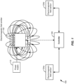
- FIG. 4 schematically illustrates electromagnetic tracking using a steered beam in the context of an AR device, according to some embodiments.
- emitted beam 402 emitted by handheld controller 410 is directed at a beam angle ⁇ . Knowing the phase delay relationship between individual phased array elements in the phased array emitter 412, the beam angle ⁇ can be computed.
- a feedback loop implemented using a bidirectional communication path 430 e.g., Bluetooth
- the communication path 430 enables data related to the handheld controller 410 to be transmitted to the AR headset 420, for example, handheld controller IMU data, phase delays of the individual phased array elements in the phased array emitter 412, the beam angle ⁇ , and the like.
- the communication path 430 enables data related to the AR headset 420 to be transmitted to the handheld controller 410, for example, AR headset IMU data, received power at the electromagnetic field sensors 422, and the like.
- the beam angle ⁇ of the emitted beam 402 may be swept and steered to maximize the received energy at the AR headset 420, and more specifically at the electromagnetic field sensors 422.
- a six DoF pose of the handheld controller 410 can be determined relative to the known pose of the AR headset 420.
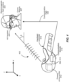
- FIG. 5A schematically illustrates a set of three electromagnetic sources (e.g., individual phased array elements) generating a steered beam at a predetermined angle, according to some embodiments.
- three phased array elements 510, 512, and 514 are included as elements of a phased array emitter 505, which is disposed in a handheld controller (e.g., the phased array emitter 412 in FIG. 4 ).
- each of the phased array elements 510, 512, and 514 can be a coil operated at a predetermined AC frequency (e.g., in the range of 20 KHz - 40 KHz) such that each coil generates an AC dipole shaped electromagnetic field.
- phased array emitter 505 all of the phased array elements 510, 512, 514 have their coils aligned with a common direction, for example, the z-direction.
- the relative orientation and arrangement of the phased array elements 510, 512, 514 is selected so that a main lobe produced by the phased array emitter 505 is directed along a most common direction that an AR headset (e.g., the AR headset 420 in FIG. 4 ) will be relative to a handheld controller (e.g., the handheld controller 410 in FIG.
- the handheld controller held in a hand of a user at about waist/mid-torso level with the palm of the hand facing to the left or the right depending on which hand the user utilizes to hold the handheld controller.
- This most common direction that the AR headset (e.g., AR headset 301) will be relative to the handheld controller (e.g., the handheld controller 306) during normal operation is illustrated in FIG. 3 .
- phased array elements 510, 512, 514 As electromagnetic radiation is emitted by each of the phased array elements 510, 512, 514, the wave nature of the electromagnetic radiation emitted results in interference between the electromagnetic radiation emitted by the phased array elements 510, 512, and 514. This interference produces regions of constructive interference and regions of destructive interference.
- phased array elements 510, 512, and 514 illustrated in FIG. 5A if the phase of each element is aligned (i.e., no delay between elements), a main lobe will be produced along the x-direction orthogonal to the plane of the figure.
- phased array elements are illustrated in FIG. 5A , embodiments of the present disclosure are not limited to this particular number and other numbers, including two phased array elements and more than three phased array elements can be utilized by embodiments of the present disclosure.
- a single coil can be utilized for each phased array element. In some embodiments, multiple coils can be utilized for each phased array element. As an example, to improve performance when the handheld controller is rotated 90° with respect to the most common direction that the AR headset will be relative to the handheld controller, a second coil for each phased array element can be utilized to increase the strength of the main lobe in a direction pointing into/out of the plane of the figure (i.e., the ⁇ x-direction).
- the emitter can be implemented as a three coil emitter as illustrated by the electromagnetic field emitter 102 in FIG. 1 .
- phased array elements 510, 512, and 514 are static (i.e., their position in the handheld controller is fixed), control of the phase delay associated with each phased array element can enable steering of the main lobe 525.
- the main lobe 525 is centered on a vector 520, which is oriented at a beam angle ⁇ having components ⁇ x , ⁇ y , and ⁇ z along the x-axis, y-axis, and z-axis, respectively.
- the vector 520 can be referred to as a central vector since it is aligned with the center of the main lobe.
- the main lobe 525 can be steered such that the vector 520 can be oriented at an arbitrary beam angle ⁇ .
- phase delays ⁇ 1 and/or ⁇ 2 corresponding to the phased array elements 512 and 514, are modified in this example, it will be appreciated that an additional phase delay ⁇ can be associated with the phased array element 510 in conjunction with control over the beam angle ⁇ associated with the main lobe 525.
- additional phase delay ⁇ is utilized, all three phase delays can be controlled to achieve the desired phase delays between the phased array elements 510, 512, 514.
- One of ordinary skill in the art would recognize many variations, modifications, and alternatives.
- Beam steering of the main lobe 525 can be used to align the vector 520 with the vector directed from the phased array emitter 505 disposed in the handheld controller to electromagnetic field sensors (e.g., the electromagnetic field sensors 422) in the AR headset. Once the vector 520 directed from the phased array emitter 505 disposed in the handheld controller and the electromagnetic field sensors in the AR headset are aligned, the energy received at the electromagnetic field sensor will be maximized since the center of the main lobe 525 will be directed to the electromagnetic field sensor. As described more fully in relation to FIG. 6 , beam steering of the main lobe 525 will be utilized to determine the orientation of the handheld controller with respect to the AR headset.
- electromagnetic field sensors e.g., the electromagnetic field sensors 422
- phased array emitter in the handheld controller and placement of the electromagnetic field sensors in the AR headset, this is not required by the present disclosure and the phased array emitter can be placed in the AR headset, with the corresponding electromagnetic field sensors placed in the handheld controller. Additionally, in some embodiments, the phased array emitter or the electromagnetic field sensors can be placed in the auxiliary unit.
- the handheld controller can support the power requirements and the weight associated with operation of the phased array emitter and, as a result, the phased array emitter will be implemented as a component disposed in the handheld controller.
- the computational work can be performed in the handheld controller 306, the AR headset 301, the belt pack 370, or a small cell (not illustrated) or distributed between these elements as appropriate.
- One of ordinary skill in the art would recognize many variations, modifications, and alternatives.
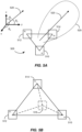
- FIG. 5B schematically illustrates a set of four electromagnetic sources in a tetrahedral arrangement, according to some embodiments.
- four phased array elements 510, 512, 514, and 516 are positioned to lie on the four vertices of a tetrahedron.
- the phased array elements 510, 512, and 514 lie in the y-z plane while the phased array element 516 is positioned at a predetermined height above the y-z plane measured along the x-axis.
- additional control is provided over a beam shape of a main lobe as well as increased control for beam steering in the y-z plane.
- FIG. 6 illustrates an example flowchart illustrating a method 600 of tracking a handheld controller position, according to some embodiments.
- the method includes determining a pose (i.e., position and orientation) of an electromagnetic field sensor (610).
- determining the pose of the electromagnetic field sensor may include determining a head pose of an AR headset including the electromagnetic field sensor.
- only the position of the electromagnetic field sensor can be determined.
- one or more IMUs in the AR headset can be used to provide this head pose determination.
- the method also includes the optional process of determining an approximate position of an electromagnetic field emitter (e.g., a handheld controller), for example, using one or more IMUs in the electromagnetic field emitter (620).
- this optional process also determines the approximate orientation (i.e., the approximate pose) of the electromagnetic field emitter (e.g., a handheld controller), for example, using one or more IMUs in the electromagnetic field emitter.
- the approximate pose can be determined based on acceleration due to gravity, which exceeds accelerations in directions orthogonal to gravity as a user is holding the handheld controller and calibrating or initializing the handheld controller.
- the phased array elements can be associated with operating frequencies as follows: the phased array element 510: ⁇ t + ⁇ , where ⁇ can be zero; the phased array element 512: ⁇ t + ⁇ 1 ; and the phased array element 514: ⁇ t + ⁇ 2 .
- beam steering can be accomplished through control of phase delays ⁇ 1 and ⁇ 2 or control of all three phases, ⁇ , ⁇ 1 , and ⁇ 2 .
- the beam steering process discussed herein can be implemented using beam steering information determined at the AR headset or at the handheld controller.
- the following process flow can be implemented when beam steering information is determined at the AR headset.
- the handheld controller transmits an electromagnetic beam via a first communications path and transmits sensor data (e.g., sensor data collected at the handheld controller) via a second communications path.
- the AR headset receives the electromagnetic beam via the first communications path and receives the handheld controller sensor data via the second communications path.
- the AR headset calculates the power associated with the electromagnetic beam and determines beam steering information based on the calculated power associated with the electromagnetic beam, the handheld device sensor data, and the AR headset sensor data. Given this beam steering information, the AR headset transmits the beam steering information via the second communications path and the handheld controller receives the beam steering information. Accordingly, the handheld controller is able to change the beam steering properties of the electromagnetic beam based on the received beam steering information.
- the received beam steering information may indicate that the handheld controller is to increase or decrease one or more of the phase delays ⁇ 1 and ⁇ 2 .
- the AR headset may determine that, based the handheld device sensor data and the AR headset sensor data, that the handheld controller is moving with respect to the AR headset, and may accordingly generate beam steering information that causes the handheld controller to increase or decrease one or more of the phase delays ⁇ 1 and ⁇ 2 such that the main beam (e.g., the main beam 525) and its corresponding vector (e.g., the vector 520) can continue to be aligned with the electromagnetic sensors in the AR headset.
- the main beam e.g., the main beam 525
- its corresponding vector e.g., the vector 520
- the handheld controller transmits an electromagnetic beam via first communications path and the AR headset receives the electromagnetic beam via the first communications path.
- the AR headset then calculates power associated with the electromagnetic beam and transmits the calculated power and AR headset sensor data to the handheld controller via the second communications path.
- the handheld controller receives the calculated power and the AR headset sensor data and determines beam steering information based on the calculated power associated with the electromagnetic beam, the AR headset sensor data, and handheld controller sensor data. Accordingly, the handheld controller is able to change beam steering properties of the electromagnetic beam based on the received beam steering information.
- calibration processes can be utilized to account for system characteristics and to improve the accuracy of the beam steering algorithm.
- control and optimization algorithms are suitable for use with embodiments of the present disclosure.
- Exemplary control and optimization algorithms that can be used to maximize the fitness function include gradient descent methods, stochastic gradient descent methods, gradient descent methods with momentum, deep learning algorithms, and the like.
- the beam may be steered by varying phase delays ⁇ 1 and ⁇ 2 by large amounts that result in large angle deviations (e.g., 10° increments) for the steered beam as the region around the handheld controller is analyzed.
- larger increments can be progressively utilized (e.g., 5°, 2°, 1°, 0.5°) to maximize the power received.
- the initialization process may be informed by ergonomic studies that provide information related to the probability that the handheld controller will be oriented in a given direction with respect to the AR headset.
- the initialization process can be initiated near angles aligned with the direction between the handheld controller and the AR headset in this orientation. This most common direction between the handheld controller and the AR headset is illustrated in FIG. 4 as beam angle ⁇ .
- beam angle ⁇ This most common direction between the handheld controller and the AR headset.
- optimization algorithms that may provide for faster convergence are included within the scope of the present disclosure.
- angular adjustments of the beam steering angle can be decreased or increased as appropriate to the particular application.
- One of ordinary skill in the art would recognize many variations, modifications, and alternatives.
- a communication path is provided between the handheld controller and the AR headset to exchange data collected during operation, for example, of the optimization algorithm.
- An example of the communication path 430 in FIG. 4 is a Bluetooth wireless link that provides for bidirectional communication between the handheld controller and the AR headset.
- This communication path can be used to transmit, for example, received power data from the AR headset to the handheld controller.
- this communication path can be used to transmit information on the beam angle (e.g., the beam angle based on the phase delays or the phase delays for computation of the beam angle at the AR headset) from the handheld controller to the AR headset.
- the communication path 430 enables control signals and data to be transmitted in a bidirectional manner between the handheld controller and the AR headset.
- IMU data generated in either the AR headset or the handheld controller can be transmitted through communication path 430.
- a Bluetooth wireless link is described as an example of the communication path 430, other communications technologies are included within the scope of the present disclosure, including WiFi wireless links, wired links such as a USB link, and the like.
- the beam steering resulting from modification of the phase delays results in increases/decreases in received power at the AR headset,.
- the electromagnetic field emitter in the handheld controller can vary the phase delays between phased array elements to steer the beam in a manner that increases the received power.
- the energy received at the electromagnetic field sensor will be maximized.
- beam steering to maximize received power can be accomplished.
- an indicator can be generated to indicate achievement of beam lock (632). Achieving beam lock will be associated with a given direction between the handheld controller and the AR headset at a given time. As the handheld controller (and/or the AR headset) moves as a function of time, the tracking algorithm will run continuously to maintain beam lock through beam steering.
- Data provided by the IMU in the handheld controller and/or the IMU in the AR headset may be utilized by the initialization and/or tracking algorithms, for example, to reduce the angular step size deviation in response to small changes in handheld controller and AR headset position and/or orientation, velocity, acceleration, or the like or to increase the angular step size deviation in response to large changes in handheld controller and AR headset position and/or orientation, velocity, acceleration, or the like.
- the angular step size deviation is modified in response to angular velocity and/or acceleration of the handheld controller since rotation of the handheld controller can result in rapid steering of the emitted beam.
- the beam angle ⁇ at which the main lobe is oriented can be determined as a function of the phase delays ⁇ 1 and ⁇ 2 associated with phased array elements 512 and 514, respectively (634).
- the beam angle ⁇ can be computed as a function of the phase delays and the geometrical arrangement.
- the beam angle ⁇ between the handheld controller and the AR headset it is known that the handheld controller and the AR headset are disposed along the vector connecting the handheld controller and the AR headset. To this information, the distance between the handheld controller and the AR headset is determined, as described more fully below, and added (634).
- Embodiments of the present disclosure utilize one of several techniques to determine the distance between the handheld controller and the AR headset.
- the measured power can be compared to a calibrated table or function relating received power to distance.
- IMU data from the handheld controller can be fused with measured power at the AR headset to refine the distance computation.
- the known electromagnetic field pattern can be used to determine the distance between the handheld controller and the AR headset given the received power.
- steering of the main lobe by a predetermined angle e.g., 5°
- a predetermined amount e.g., 10%
- phase delays can be varied to steer the beam by the predetermined angle (for example, through a series of angles) and the decrease(s) in received power can be used to compute the distance.
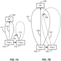
- phased array emitter 712 is illustrated after it has been translated to position x 2 (Tx(x 2 )).
- the position translation information can be obtained by analyzing IMU data generated by the handheld controller and transmitted to the AR headset since this IMU data can be used to track handheld controller pose.
- IMU data related to handheld controller pose is fused with measurements of the electromagnetic power received by the AR headset to provide handheld controller pose values.
- the transmission pattern is maintained given the new phased array emitter position (i.e., x 2 )
- the power received at electromagnetic field sensor 720 will decrease as illustrated by a vector 717 in FIG. 7A , intersecting the main lobe at position 718. Because the main lobe amplitude is significantly decreased at the position 718, a function can be generated that correlates translation distance with received power for the given distance.
- FIG. 7B schematically illustrates an example of variation in received signal as a function of two emitter positions, according to some embodiments.
- the distance equal to the length of a vector 735 is greater than the distance equal to the length of the vector 715 illustrated in FIG. 7A .
- the phased array emitter 730 is positioned at position x 1 and is characterized by a transmission pattern 731 having a central angle aligned with the vector 735. For purposes of clarity, only the central or main lobe of the transmission pattern is illustrated.
- the electromagnetic sensor 740 is positioned at a distance equal to the length of the vector 735 from the phased array emitter 730 and beam lock has been achieved for the phased array emitter 730 at position x 1 (Tx(x 1 )).
- the decrease in received power for a given translation i.e., from position x 1 to position x 2
- an additional function can be generated that correlates translation distance with received power for the larger given distance illustrated in FIG. 7B .
- P x d Power Received d Emitter Position
- embodiments of the present disclosure can utilize changes in position of the handheld controller, as well as changes in orientation of the handheld controller to determine emitter to sensor distance.
- the increase or decrease in received power as a function of changes in the position of the handheld controller, which is utilized to determine emitter to sensor distance is performed in a short period of time compared to the active tracking loop that can redirect the steerable .
- embodiments enable distance measurements in conjunction with active tracking as discussed, for example, with respect to FIG. 6 .
- the functionality of the handheld controller is enhanced utilizing information collected and/or available at the handheld controller. For example, if a change in IMU data is determined at the handheld controller, for example, a determination that the handheld controller has been translated in a given direction by a given amount or rotated around a given axis by a given amount, beam steering can be initiated at the handheld controller in advance of feedback being received from the electromagnetic field sensors in the AR headset.
- a change in IMU data is determined at the handheld controller, for example, a determination that the handheld controller has been translated in a given direction by a given amount or rotated around a given axis by a given amount
- beam steering can be initiated at the handheld controller in advance of feedback being received from the electromagnetic field sensors in the AR headset.
- embodiments of the present disclosure in which the handheld controller performs beam steering in response to feedback from the AR headset as well as embodiments in which the handheld controller initiates beam steering in response to data measured and/or available at the handheld controller are included within the scope of the present disclosure.
- combinations of these approaches are
- IMUs incorporated in the handheld controller can be utilized to provide information on handheld controller pose that can be integrated with the beam angle and the distance between the handheld controller and the AR headset computed above.
- One of ordinary skill in the art would recognize many variations, modifications, and alternatives.
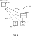
- FIG. 8 schematically illustrates an augmented reality system in communication with a 5G cellular mobile communications system.
- a 5G transmitter 810 also referred to as a small cell (e.g., a femtocell, a picocell, or a microcell)
- an AR system 805 including an AR headset 820, an electromagnetic handheld controller 822, and an auxiliary unit 824.
- Communications devices for example, 5G devices, are thus included in the AR system in some embodiments of the present disclosure.
- the AR headset 820, the electromagnetic handheld controller 822, and the auxiliary unit 824 illustrated in FIG. 8 may correspond to the AR headset 301, the electromagnetic field emitter 302, and the belt pack 370 illustrated in FIG. 3 , respectively.
- beamforming can be utilized by the 5G transmitter 810 to direct the communication path from the 5G transmitter to the AR system 805, for example, along the beam path 812 for communication with the AR headset 820 or along the beam path 814 for communication with the auxiliary unit 824.
- the spatial proximity of the various elements of the AR system 805 are close enough to each other that the beamforming performing by the 5G transmitter 810 is characterized by a single beam path connecting the 5G transmitter and the AR system without the specificity in relation to particular elements of the AR system.
- beamforming can be performed at the AR system 805 for communication with the 5G transmitter 810 as illustrated by the beam path 830.
- beamforming at the handheld controller is illustrated by the beam path 830, embodiments of the present disclosure can also utilize beamforming at the auxiliary unit or the AR headset to facilitate communication with the 5G transmitter.
- beamforming can be performed at one or more elements of the AR system to facilitate communications with the 5G transmitter.
- beamforming can be performed at one or more of the elements of the AR system, including the AR headset, the handheld controller, and/or the auxiliary unit.
- embodiments of the present disclosure are not limited to this particular communications standard and other communication hubs having a known position can be utilized within the scope of the present disclosure.
- the AR system may use information that it independently collects about its changing position or pose in order to more accurately perform beam steering along beam path 830, and may communicate such information about its changing position or pose to the 5G transmitter in order for the 5G transmitter to more accurately perform beam steering along the beam paths 812 and 814.
Landscapes
- Engineering & Computer Science (AREA)
- Physics & Mathematics (AREA)
- General Engineering & Computer Science (AREA)
- Multimedia (AREA)
- Theoretical Computer Science (AREA)
- General Physics & Mathematics (AREA)
- Human Computer Interaction (AREA)
- Remote Sensing (AREA)
- Radar, Positioning & Navigation (AREA)
- Optics & Photonics (AREA)
- Computer Networks & Wireless Communication (AREA)
- Electromagnetism (AREA)
- Variable-Direction Aerials And Aerial Arrays (AREA)
- Measurement Of Length, Angles, Or The Like Using Electric Or Magnetic Means (AREA)
- User Interface Of Digital Computer (AREA)
- Radar Systems Or Details Thereof (AREA)
- Position Input By Displaying (AREA)
Claims (7)
- Elektromagnetisches Verfolgungssystem, umfassend:
eine Handsteuerung (306), die einen elektromagnetischen Sender (102) beinhaltet, wobei der elektromagnetische Sender (102) Folgendes beinhaltet:ein erstes phasengesteuertes Array-Element (510), gekennzeichnet durch eine erste Phase; undein zweites phasengesteuertes Array-Element (512), gekennzeichnet durch eine zweite Phase, die sich von der ersten Phase unterscheidet;wobei das erste phasengesteuerte Array-Element (510) und das zweite phasengesteuerte Array-Element (512) dazu konfiguriert sind, einen lenkbaren elektromagnetischen Strahl zu erzeugen, der durch ein elektromagnetisches Feldmuster gekennzeichnet ist;ein Helmdisplay der erweiterten Realität (301), das einen elektromagnetischen Sensor (304) beinhaltet, der dazu konfiguriert ist, das elektromagnetische Feldmuster zu erfassen; undeine Rechenvorrichtung, die zu Folgendem konfiguriert ist:Bestimmen einer Pose des elektromagnetischen Sensors (304); Steuern der ersten Phase, um den elektromagnetischen Strahl zu lenken, um die Leistungsaufnahme an dem elektromagnetischen Sensor (304) zu erhöhen; undBestimmen einer Pose der Handsteuerung (306) unter Verwendung der Pose des elektromagnetischen Sensors (304) und des an dem elektromagnetischen Sensor (304) erfassten elektromagnetischen Feldmusters. - Elektromagnetisches Verfolgungssystem nach Anspruch 1, wobei die Rechenvorrichtung ferner zu Folgendem konfiguriert ist:
eine Position und Ausrichtung der Handsteuerung (306) basierend auf dem elektromagnetischen Feldmuster digital zu berechnen. - Elektromagnetisches Verfolgungssystem nach Anspruch 1, wobei mindestens einer des einen oder der mehreren Prozessoren in der Handsteuerung (306) angeordnet ist.
- Elektromagnetisches Verfolgungssystem nach Anspruch 1, ferner umfassend eine Hilfseinheit, die die Handsteuerung (306) beinhaltet.
- Elektromagnetisches Verfolgungssystem nach Anspruch 4, wobei die Hilfseinheit eine Gürteltasche (301, 370) umfasst.
- Elektromagnetisches Verfolgungssystem nach Anspruch 1, wobei der elektromagnetische Sender (102) ferner ein drittes phasengesteuertes Array-Element umfasst, wobei das erste phasengesteuerte Array-Element, das zweite phasengesteuerte Array-Element und das dritte phasengesteuerte Array-Element in einer Ebene angeordnet sind.
- Elektromagnetisches Verfolgungssystem nach Anspruch 6, wobei der elektromagnetische Sender (102) ferner ein viertes phasengesteuertes Array-Element umfasst, wobei das erste phasengesteuerte Array-Element, das zweite phasengesteuerte Array-Element und das dritte phasengesteuerte Array-Element drei Ecken eines Tetraeders bilden und das vierte phasengesteuerte Array-Element eine vierte Ecke des Tetraeders bildet.
Applications Claiming Priority (2)
| Application Number | Priority Date | Filing Date | Title |
|---|---|---|---|
| US201962811914P | 2019-02-28 | 2019-02-28 | |
| PCT/US2020/020178 WO2020176779A1 (en) | 2019-02-28 | 2020-02-27 | Method and system utilizing phased array beamforming for six degree of freedom tracking for an emitter in augmented reality systems |
Publications (3)
| Publication Number | Publication Date |
|---|---|
| EP3930865A1 EP3930865A1 (de) | 2022-01-05 |
| EP3930865A4 EP3930865A4 (de) | 2022-07-27 |
| EP3930865B1 true EP3930865B1 (de) | 2025-04-02 |
Family
ID=72239149
Family Applications (1)
| Application Number | Title | Priority Date | Filing Date |
|---|---|---|---|
| EP20762410.7A Active EP3930865B1 (de) | 2019-02-28 | 2020-02-27 | Verfahren und system unter verwendung von phasengesteuerter array-strahlformung für die verfolgung eines senders mit sechs freiheitsgraden in systemen der erweiterten realität |
Country Status (5)
| Country | Link |
|---|---|
| US (2) | US11726582B2 (de) |
| EP (1) | EP3930865B1 (de) |
| JP (2) | JP7580173B2 (de) |
| CN (1) | CN113543863B (de) |
| WO (1) | WO2020176779A1 (de) |
Families Citing this family (9)
| Publication number | Priority date | Publication date | Assignee | Title |
|---|---|---|---|---|
| EP3930865B1 (de) | 2019-02-28 | 2025-04-02 | Magic Leap, Inc. | Verfahren und system unter verwendung von phasengesteuerter array-strahlformung für die verfolgung eines senders mit sechs freiheitsgraden in systemen der erweiterten realität |
| CN111061363A (zh) * | 2019-11-21 | 2020-04-24 | 青岛小鸟看看科技有限公司 | 一种虚拟现实系统 |
| CN112822480B (zh) * | 2020-12-31 | 2022-05-17 | 青岛小鸟看看科技有限公司 | Vr系统及其定位追踪方法 |
| US12118679B2 (en) * | 2022-01-06 | 2024-10-15 | Htc Corporation | Data processing system, method for determining coordinates, and computer readable storage medium |
| CN114557780B (zh) * | 2022-03-01 | 2024-01-26 | 长春理工大学 | 一种辅助外科手术的三维定位系统及方法 |
| CN114885243B (zh) * | 2022-05-12 | 2024-07-02 | 歌尔股份有限公司 | 头显设备、音频输出控制方法及可读存储介质 |
| CN114976595A (zh) * | 2022-05-17 | 2022-08-30 | 南昌黑鲨科技有限公司 | 一种智能天线系统 |
| CN117368848B (zh) * | 2023-12-06 | 2024-05-03 | 中国海洋大学 | 基于长短期记忆神经网络的虚拟阵元波束形成方法及系统 |
| TWI907273B (zh) * | 2024-12-22 | 2025-12-01 | 宏達國際電子股份有限公司 | 主機、追蹤系統以及追蹤方法 |
Family Cites Families (18)
| Publication number | Priority date | Publication date | Assignee | Title |
|---|---|---|---|---|
| WO2001056007A1 (en) * | 2000-01-28 | 2001-08-02 | Intersense, Inc. | Self-referenced tracking |
| JP3813898B2 (ja) * | 2002-04-23 | 2006-08-23 | 日本電信電話株式会社 | フェーズドアレーアンテナとそのビーム形成回路及びビーム形成方法 |
| US8104654B2 (en) * | 2007-02-13 | 2012-01-31 | Overton Enterprises, Llc | Belt with expandable pouch |
| CN101256673A (zh) * | 2008-03-18 | 2008-09-03 | 中国计量学院 | 用于在实时视频跟踪系统中跟踪手臂运动的方法 |
| US8795082B2 (en) * | 2010-01-25 | 2014-08-05 | Rambus Inc. | Directional beam steering system and method to detect location and motion |
| US10209771B2 (en) * | 2016-09-30 | 2019-02-19 | Sony Interactive Entertainment Inc. | Predictive RF beamforming for head mounted display |
| JP5611294B2 (ja) * | 2012-09-05 | 2014-10-22 | 富士通株式会社 | 探知測距装置 |
| US9616350B2 (en) * | 2014-05-21 | 2017-04-11 | Universal City Studios Llc | Enhanced interactivity in an amusement park environment using passive tracking elements |
| US9665174B2 (en) * | 2015-02-20 | 2017-05-30 | Sony Interactive Entertainment Inc. | Magnetic tracking of glove fingertips with peripheral devices |
| CN112764536B (zh) * | 2015-03-05 | 2025-04-01 | 奇跃公司 | 用于增强现实的系统和方法 |
| US10180734B2 (en) * | 2015-03-05 | 2019-01-15 | Magic Leap, Inc. | Systems and methods for augmented reality |
| EP3458167B1 (de) * | 2016-04-26 | 2022-10-19 | Magic Leap, Inc. | Elektromagnetische verfolgung mit systemen für erweiterte realität |
| US10254546B2 (en) | 2016-06-06 | 2019-04-09 | Microsoft Technology Licensing, Llc | Optically augmenting electromagnetic tracking in mixed reality |
| US10638124B2 (en) * | 2017-04-10 | 2020-04-28 | Intel Corporation | Using dynamic vision sensors for motion detection in head mounted displays |
| GB2569603B (en) * | 2017-12-21 | 2020-04-01 | Sony Interactive Entertainment Inc | Position tracking apparatus and method |
| CA3031276A1 (en) * | 2018-02-08 | 2019-08-08 | Ascension Technology Corporation | Compensating for distortion in an electromagnetic tracking system |
| US10651566B2 (en) * | 2018-04-23 | 2020-05-12 | The Boeing Company | Unit cell antenna for phased arrays |
| EP3930865B1 (de) * | 2019-02-28 | 2025-04-02 | Magic Leap, Inc. | Verfahren und system unter verwendung von phasengesteuerter array-strahlformung für die verfolgung eines senders mit sechs freiheitsgraden in systemen der erweiterten realität |
-
2020
- 2020-02-27 EP EP20762410.7A patent/EP3930865B1/de active Active
- 2020-02-27 JP JP2021549972A patent/JP7580173B2/ja active Active
- 2020-02-27 CN CN202080017238.9A patent/CN113543863B/zh active Active
- 2020-02-27 WO PCT/US2020/020178 patent/WO2020176779A1/en not_active Ceased
-
2021
- 2021-08-27 US US17/458,890 patent/US11726582B2/en active Active
-
2023
- 2023-06-21 US US18/212,645 patent/US12111981B2/en active Active
-
2024
- 2024-10-16 JP JP2024181382A patent/JP2025020157A/ja active Pending
Also Published As
| Publication number | Publication date |
|---|---|
| WO2020176779A1 (en) | 2020-09-03 |
| JP2025020157A (ja) | 2025-02-12 |
| EP3930865A1 (de) | 2022-01-05 |
| JP2022521986A (ja) | 2022-04-13 |
| US20220050533A1 (en) | 2022-02-17 |
| EP3930865A4 (de) | 2022-07-27 |
| US11726582B2 (en) | 2023-08-15 |
| CN113543863A (zh) | 2021-10-22 |
| US20230333670A1 (en) | 2023-10-19 |
| JP7580173B2 (ja) | 2024-11-11 |
| US12111981B2 (en) | 2024-10-08 |
| CN113543863B (zh) | 2025-09-23 |
Similar Documents
| Publication | Publication Date | Title |
|---|---|---|
| US12111981B2 (en) | Method and system utilizing phased array beamforming for six degree of freedom tracking for an emitter in augmented reality systems | |
| CN109791435B (zh) | 虚拟现实或增强现实显示系统中磁传感器和光学传感器的校准 | |
| CN114995647B (zh) | 用于增强现实的系统和方法 | |
| JP2024045724A (ja) | 電磁追跡のための周囲電磁歪み補正 | |
| CN109620104B (zh) | 胶囊内窥镜及其定位方法及系统 | |
| US12061743B2 (en) | Hand and totem input fusion for wearable systems | |
| KR20190094954A (ko) | 전자장치의 움직임 측정 장치 및 방법 | |
| JP7806161B2 (ja) | 拡張現実システムにおける電磁追跡のための指向性エミッタ/センサ | |
| CN113383294B (zh) | 用于解决六自由度姿态测量中的半球模糊的方法和系统 | |
| JPH0954542A (ja) | 動作検出装置、シミュレータ装置及び動作検出方法 | |
| Vincent | Portable indoor multi-user position tracking system for immersive virtual environments using sensor fusion with multidimensional scaling | |
| Liu et al. | Low-Cost VR Interaction Device: Dynamic CoG Mapping and Adaptive Compensation Design | |
| 장혁 | A Mobile VR Motion Controller with 6 DoF positioning using Light Polarization | |
| KR20160059847A (ko) | 무선 컨트롤러 시스템 |
Legal Events
| Date | Code | Title | Description |
|---|---|---|---|
| STAA | Information on the status of an ep patent application or granted ep patent |
Free format text: STATUS: THE INTERNATIONAL PUBLICATION HAS BEEN MADE |
|
| PUAI | Public reference made under article 153(3) epc to a published international application that has entered the european phase |
Free format text: ORIGINAL CODE: 0009012 |
|
| STAA | Information on the status of an ep patent application or granted ep patent |
Free format text: STATUS: REQUEST FOR EXAMINATION WAS MADE |
|
| 17P | Request for examination filed |
Effective date: 20210921 |
|
| AK | Designated contracting states |
Kind code of ref document: A1 Designated state(s): AL AT BE BG CH CY CZ DE DK EE ES FI FR GB GR HR HU IE IS IT LI LT LU LV MC MK MT NL NO PL PT RO RS SE SI SK SM TR |
|
| RIC1 | Information provided on ipc code assigned before grant |
Ipc: G06F 3/01 20060101ALI20220322BHEP Ipc: G01S 13/06 20060101ALI20220322BHEP Ipc: H01Q 3/26 20060101ALI20220322BHEP Ipc: G06T 19/00 20110101ALI20220322BHEP Ipc: G02B 27/01 20060101ALI20220322BHEP Ipc: A63F 13/92 20140101ALI20220322BHEP Ipc: A63F 13/428 20140101ALI20220322BHEP Ipc: A63F 13/24 20140101ALI20220322BHEP Ipc: A63F 13/235 20140101ALI20220322BHEP Ipc: A63F 13/21 20140101AFI20220322BHEP |
|
| DAV | Request for validation of the european patent (deleted) | ||
| DAX | Request for extension of the european patent (deleted) | ||
| REG | Reference to a national code |
Ref country code: DE Ref legal event code: R079 Free format text: PREVIOUS MAIN CLASS: A63F0013920000 Ipc: A63F0013210000 Ref document number: 602020048756 Country of ref document: DE |
|
| A4 | Supplementary search report drawn up and despatched |
Effective date: 20220628 |
|
| RIC1 | Information provided on ipc code assigned before grant |
Ipc: G06F 3/01 20060101ALI20220622BHEP Ipc: G01S 13/06 20060101ALI20220622BHEP Ipc: H01Q 3/26 20060101ALI20220622BHEP Ipc: G06T 19/00 20110101ALI20220622BHEP Ipc: G02B 27/01 20060101ALI20220622BHEP Ipc: A63F 13/92 20140101ALI20220622BHEP Ipc: A63F 13/428 20140101ALI20220622BHEP Ipc: A63F 13/24 20140101ALI20220622BHEP Ipc: A63F 13/235 20140101ALI20220622BHEP Ipc: A63F 13/21 20140101AFI20220622BHEP |
|
| P01 | Opt-out of the competence of the unified patent court (upc) registered |
Effective date: 20230607 |
|
| GRAP | Despatch of communication of intention to grant a patent |
Free format text: ORIGINAL CODE: EPIDOSNIGR1 |
|
| STAA | Information on the status of an ep patent application or granted ep patent |
Free format text: STATUS: GRANT OF PATENT IS INTENDED |
|
| RIC1 | Information provided on ipc code assigned before grant |
Ipc: G06F 3/01 20060101ALI20241127BHEP Ipc: G01S 13/06 20060101ALI20241127BHEP Ipc: H01Q 3/26 20060101ALI20241127BHEP Ipc: G06T 19/00 20110101ALI20241127BHEP Ipc: G02B 27/01 20060101ALI20241127BHEP Ipc: A63F 13/92 20140101ALI20241127BHEP Ipc: A63F 13/428 20140101ALI20241127BHEP Ipc: A63F 13/24 20140101ALI20241127BHEP Ipc: A63F 13/235 20140101ALI20241127BHEP Ipc: A63F 13/21 20140101AFI20241127BHEP |
|
| INTG | Intention to grant announced |
Effective date: 20241209 |
|
| GRAS | Grant fee paid |
Free format text: ORIGINAL CODE: EPIDOSNIGR3 |
|
| GRAA | (expected) grant |
Free format text: ORIGINAL CODE: 0009210 |
|
| STAA | Information on the status of an ep patent application or granted ep patent |
Free format text: STATUS: THE PATENT HAS BEEN GRANTED |
|
| AK | Designated contracting states |
Kind code of ref document: B1 Designated state(s): AL AT BE BG CH CY CZ DE DK EE ES FI FR GB GR HR HU IE IS IT LI LT LU LV MC MK MT NL NO PL PT RO RS SE SI SK SM TR |
|
| REG | Reference to a national code |
Ref country code: GB Ref legal event code: FG4D |
|
| REG | Reference to a national code |
Ref country code: CH Ref legal event code: EP |
|
| REG | Reference to a national code |
Ref country code: NL Ref legal event code: FP |
|
| REG | Reference to a national code |
Ref country code: IE Ref legal event code: FG4D |
|
| REG | Reference to a national code |
Ref country code: DE Ref legal event code: R096 Ref document number: 602020048756 Country of ref document: DE |
|
| REG | Reference to a national code |
Ref country code: AT Ref legal event code: MK05 Ref document number: 1780732 Country of ref document: AT Kind code of ref document: T Effective date: 20250402 |
|
| PG25 | Lapsed in a contracting state [announced via postgrant information from national office to epo] |
Ref country code: FI Free format text: LAPSE BECAUSE OF FAILURE TO SUBMIT A TRANSLATION OF THE DESCRIPTION OR TO PAY THE FEE WITHIN THE PRESCRIBED TIME-LIMIT Effective date: 20250402 Ref country code: PT Free format text: LAPSE BECAUSE OF FAILURE TO SUBMIT A TRANSLATION OF THE DESCRIPTION OR TO PAY THE FEE WITHIN THE PRESCRIBED TIME-LIMIT Effective date: 20250804 Ref country code: ES Free format text: LAPSE BECAUSE OF FAILURE TO SUBMIT A TRANSLATION OF THE DESCRIPTION OR TO PAY THE FEE WITHIN THE PRESCRIBED TIME-LIMIT Effective date: 20250402 |
|
| REG | Reference to a national code |
Ref country code: LT Ref legal event code: MG9D |
|
| PG25 | Lapsed in a contracting state [announced via postgrant information from national office to epo] |
Ref country code: GR Free format text: LAPSE BECAUSE OF FAILURE TO SUBMIT A TRANSLATION OF THE DESCRIPTION OR TO PAY THE FEE WITHIN THE PRESCRIBED TIME-LIMIT Effective date: 20250703 Ref country code: NO Free format text: LAPSE BECAUSE OF FAILURE TO SUBMIT A TRANSLATION OF THE DESCRIPTION OR TO PAY THE FEE WITHIN THE PRESCRIBED TIME-LIMIT Effective date: 20250702 |
|
| PG25 | Lapsed in a contracting state [announced via postgrant information from national office to epo] |
Ref country code: PL Free format text: LAPSE BECAUSE OF FAILURE TO SUBMIT A TRANSLATION OF THE DESCRIPTION OR TO PAY THE FEE WITHIN THE PRESCRIBED TIME-LIMIT Effective date: 20250402 |
|
| PG25 | Lapsed in a contracting state [announced via postgrant information from national office to epo] |
Ref country code: BG Free format text: LAPSE BECAUSE OF FAILURE TO SUBMIT A TRANSLATION OF THE DESCRIPTION OR TO PAY THE FEE WITHIN THE PRESCRIBED TIME-LIMIT Effective date: 20250402 |
|
| PG25 | Lapsed in a contracting state [announced via postgrant information from national office to epo] |
Ref country code: HR Free format text: LAPSE BECAUSE OF FAILURE TO SUBMIT A TRANSLATION OF THE DESCRIPTION OR TO PAY THE FEE WITHIN THE PRESCRIBED TIME-LIMIT Effective date: 20250402 |
|
| PG25 | Lapsed in a contracting state [announced via postgrant information from national office to epo] |
Ref country code: AT Free format text: LAPSE BECAUSE OF FAILURE TO SUBMIT A TRANSLATION OF THE DESCRIPTION OR TO PAY THE FEE WITHIN THE PRESCRIBED TIME-LIMIT Effective date: 20250402 |
|
| PG25 | Lapsed in a contracting state [announced via postgrant information from national office to epo] |
Ref country code: RS Free format text: LAPSE BECAUSE OF FAILURE TO SUBMIT A TRANSLATION OF THE DESCRIPTION OR TO PAY THE FEE WITHIN THE PRESCRIBED TIME-LIMIT Effective date: 20250702 |
|
| PG25 | Lapsed in a contracting state [announced via postgrant information from national office to epo] |
Ref country code: IS Free format text: LAPSE BECAUSE OF FAILURE TO SUBMIT A TRANSLATION OF THE DESCRIPTION OR TO PAY THE FEE WITHIN THE PRESCRIBED TIME-LIMIT Effective date: 20250802 |
|
| PG25 | Lapsed in a contracting state [announced via postgrant information from national office to epo] |
Ref country code: LV Free format text: LAPSE BECAUSE OF FAILURE TO SUBMIT A TRANSLATION OF THE DESCRIPTION OR TO PAY THE FEE WITHIN THE PRESCRIBED TIME-LIMIT Effective date: 20250402 |
|
| REG | Reference to a national code |
Ref country code: DE Ref legal event code: R097 Ref document number: 602020048756 Country of ref document: DE |
|
| PG25 | Lapsed in a contracting state [announced via postgrant information from national office to epo] |
Ref country code: SM Free format text: LAPSE BECAUSE OF FAILURE TO SUBMIT A TRANSLATION OF THE DESCRIPTION OR TO PAY THE FEE WITHIN THE PRESCRIBED TIME-LIMIT Effective date: 20250402 Ref country code: DK Free format text: LAPSE BECAUSE OF FAILURE TO SUBMIT A TRANSLATION OF THE DESCRIPTION OR TO PAY THE FEE WITHIN THE PRESCRIBED TIME-LIMIT Effective date: 20250402 |
|
| PG25 | Lapsed in a contracting state [announced via postgrant information from national office to epo] |
Ref country code: CZ Free format text: LAPSE BECAUSE OF FAILURE TO SUBMIT A TRANSLATION OF THE DESCRIPTION OR TO PAY THE FEE WITHIN THE PRESCRIBED TIME-LIMIT Effective date: 20250402 |
|
| PG25 | Lapsed in a contracting state [announced via postgrant information from national office to epo] |
Ref country code: EE Free format text: LAPSE BECAUSE OF FAILURE TO SUBMIT A TRANSLATION OF THE DESCRIPTION OR TO PAY THE FEE WITHIN THE PRESCRIBED TIME-LIMIT Effective date: 20250402 |
|
| PG25 | Lapsed in a contracting state [announced via postgrant information from national office to epo] |
Ref country code: RO Free format text: LAPSE BECAUSE OF FAILURE TO SUBMIT A TRANSLATION OF THE DESCRIPTION OR TO PAY THE FEE WITHIN THE PRESCRIBED TIME-LIMIT Effective date: 20250402 Ref country code: SK Free format text: LAPSE BECAUSE OF FAILURE TO SUBMIT A TRANSLATION OF THE DESCRIPTION OR TO PAY THE FEE WITHIN THE PRESCRIBED TIME-LIMIT Effective date: 20250402 |
|
| PG25 | Lapsed in a contracting state [announced via postgrant information from national office to epo] |
Ref country code: IT Free format text: LAPSE BECAUSE OF FAILURE TO SUBMIT A TRANSLATION OF THE DESCRIPTION OR TO PAY THE FEE WITHIN THE PRESCRIBED TIME-LIMIT Effective date: 20250402 |
|
| PLBE | No opposition filed within time limit |
Free format text: ORIGINAL CODE: 0009261 |
|
| STAA | Information on the status of an ep patent application or granted ep patent |
Free format text: STATUS: NO OPPOSITION FILED WITHIN TIME LIMIT |
|
| REG | Reference to a national code |
Ref country code: CH Ref legal event code: L10 Free format text: ST27 STATUS EVENT CODE: U-0-0-L10-L00 (AS PROVIDED BY THE NATIONAL OFFICE) Effective date: 20260211 |
|
| PGFP | Annual fee paid to national office [announced via postgrant information from national office to epo] |
Ref country code: NL Payment date: 20260121 Year of fee payment: 7 |
|
| 26N | No opposition filed |
Effective date: 20260105 |