EP3930792B1 - Nadelschutzentferner für autoinjektor - Google Patents
Nadelschutzentferner für autoinjektor Download PDFInfo
- Publication number
- EP3930792B1 EP3930792B1 EP20706285.2A EP20706285A EP3930792B1 EP 3930792 B1 EP3930792 B1 EP 3930792B1 EP 20706285 A EP20706285 A EP 20706285A EP 3930792 B1 EP3930792 B1 EP 3930792B1
- Authority
- EP
- European Patent Office
- Prior art keywords
- distal end
- retainer
- syringe
- shield
- cap remover
- Prior art date
- Legal status (The legal status is an assumption and is not a legal conclusion. Google has not performed a legal analysis and makes no representation as to the accuracy of the status listed.)
- Active
Links
Images


Classifications
-
- A—HUMAN NECESSITIES
- A61—MEDICAL OR VETERINARY SCIENCE; HYGIENE
- A61M—DEVICES FOR INTRODUCING MEDIA INTO, OR ONTO, THE BODY; DEVICES FOR TRANSDUCING BODY MEDIA OR FOR TAKING MEDIA FROM THE BODY; DEVICES FOR PRODUCING OR ENDING SLEEP OR STUPOR
- A61M5/00—Devices for bringing media into the body in a subcutaneous, intra-vascular or intramuscular way; Accessories therefor, e.g. filling or cleaning devices, arm-rests
- A61M5/178—Syringes
- A61M5/20—Automatic syringes, e.g. with automatically actuated piston rod, with automatic needle injection, filling automatically
-
- A—HUMAN NECESSITIES
- A61—MEDICAL OR VETERINARY SCIENCE; HYGIENE
- A61M—DEVICES FOR INTRODUCING MEDIA INTO, OR ONTO, THE BODY; DEVICES FOR TRANSDUCING BODY MEDIA OR FOR TAKING MEDIA FROM THE BODY; DEVICES FOR PRODUCING OR ENDING SLEEP OR STUPOR
- A61M5/00—Devices for bringing media into the body in a subcutaneous, intra-vascular or intramuscular way; Accessories therefor, e.g. filling or cleaning devices, arm-rests
- A61M5/178—Syringes
- A61M5/31—Details
- A61M5/32—Needles; Details of needles pertaining to their connection with syringe or hub; Accessories for bringing the needle into, or holding the needle on, the body; Devices for protection of needles
- A61M5/3202—Devices for protection of the needle before use, e.g. caps
- A61M5/3204—Needle cap remover, i.e. devices to dislodge protection cover from needle or needle hub, e.g. deshielding devices
-
- A—HUMAN NECESSITIES
- A61—MEDICAL OR VETERINARY SCIENCE; HYGIENE
- A61M—DEVICES FOR INTRODUCING MEDIA INTO, OR ONTO, THE BODY; DEVICES FOR TRANSDUCING BODY MEDIA OR FOR TAKING MEDIA FROM THE BODY; DEVICES FOR PRODUCING OR ENDING SLEEP OR STUPOR
- A61M5/00—Devices for bringing media into the body in a subcutaneous, intra-vascular or intramuscular way; Accessories therefor, e.g. filling or cleaning devices, arm-rests
- A61M5/178—Syringes
- A61M5/20—Automatic syringes, e.g. with automatically actuated piston rod, with automatic needle injection, filling automatically
- A61M2005/2006—Having specific accessories
- A61M2005/2013—Having specific accessories triggering of discharging means by contact of injector with patient body
-
- A—HUMAN NECESSITIES
- A61—MEDICAL OR VETERINARY SCIENCE; HYGIENE
- A61M—DEVICES FOR INTRODUCING MEDIA INTO, OR ONTO, THE BODY; DEVICES FOR TRANSDUCING BODY MEDIA OR FOR TAKING MEDIA FROM THE BODY; DEVICES FOR PRODUCING OR ENDING SLEEP OR STUPOR
- A61M5/00—Devices for bringing media into the body in a subcutaneous, intra-vascular or intramuscular way; Accessories therefor, e.g. filling or cleaning devices, arm-rests
- A61M5/178—Syringes
- A61M5/20—Automatic syringes, e.g. with automatically actuated piston rod, with automatic needle injection, filling automatically
- A61M2005/2073—Automatic syringes, e.g. with automatically actuated piston rod, with automatic needle injection, filling automatically preventing premature release, e.g. by making use of a safety lock
-
- A—HUMAN NECESSITIES
- A61—MEDICAL OR VETERINARY SCIENCE; HYGIENE
- A61M—DEVICES FOR INTRODUCING MEDIA INTO, OR ONTO, THE BODY; DEVICES FOR TRANSDUCING BODY MEDIA OR FOR TAKING MEDIA FROM THE BODY; DEVICES FOR PRODUCING OR ENDING SLEEP OR STUPOR
- A61M5/00—Devices for bringing media into the body in a subcutaneous, intra-vascular or intramuscular way; Accessories therefor, e.g. filling or cleaning devices, arm-rests
- A61M5/178—Syringes
- A61M5/31—Details
- A61M2005/3103—Leak prevention means for distal end of syringes, i.e. syringe end for mounting a needle
- A61M2005/3107—Leak prevention means for distal end of syringes, i.e. syringe end for mounting a needle for needles
-
- A—HUMAN NECESSITIES
- A61—MEDICAL OR VETERINARY SCIENCE; HYGIENE
- A61M—DEVICES FOR INTRODUCING MEDIA INTO, OR ONTO, THE BODY; DEVICES FOR TRANSDUCING BODY MEDIA OR FOR TAKING MEDIA FROM THE BODY; DEVICES FOR PRODUCING OR ENDING SLEEP OR STUPOR
- A61M5/00—Devices for bringing media into the body in a subcutaneous, intra-vascular or intramuscular way; Accessories therefor, e.g. filling or cleaning devices, arm-rests
- A61M5/178—Syringes
- A61M5/31—Details
- A61M5/32—Needles; Details of needles pertaining to their connection with syringe or hub; Accessories for bringing the needle into, or holding the needle on, the body; Devices for protection of needles
- A61M5/3205—Apparatus for removing or disposing of used needles or syringes, e.g. containers; Means for protection against accidental injuries from used needles
- A61M5/321—Means for protection against accidental injuries by used needles
- A61M5/3243—Means for protection against accidental injuries by used needles being axially-extensible, e.g. protective sleeves coaxially slidable on the syringe barrel
- A61M5/3245—Constructional features thereof, e.g. to improve manipulation or functioning
- A61M2005/3254—Shielding of proximal needles, e.g. for pen needles
-
- A—HUMAN NECESSITIES
- A61—MEDICAL OR VETERINARY SCIENCE; HYGIENE
- A61M—DEVICES FOR INTRODUCING MEDIA INTO, OR ONTO, THE BODY; DEVICES FOR TRANSDUCING BODY MEDIA OR FOR TAKING MEDIA FROM THE BODY; DEVICES FOR PRODUCING OR ENDING SLEEP OR STUPOR
- A61M2205/00—General characteristics of the apparatus
- A61M2205/02—General characteristics of the apparatus characterised by a particular materials
- A61M2205/0216—Materials providing elastic properties, e.g. for facilitating deformation and avoid breaking
-
- A—HUMAN NECESSITIES
- A61—MEDICAL OR VETERINARY SCIENCE; HYGIENE
- A61M—DEVICES FOR INTRODUCING MEDIA INTO, OR ONTO, THE BODY; DEVICES FOR TRANSDUCING BODY MEDIA OR FOR TAKING MEDIA FROM THE BODY; DEVICES FOR PRODUCING OR ENDING SLEEP OR STUPOR
- A61M2205/00—General characteristics of the apparatus
- A61M2205/02—General characteristics of the apparatus characterised by a particular materials
- A61M2205/0266—Shape memory materials
-
- A—HUMAN NECESSITIES
- A61—MEDICAL OR VETERINARY SCIENCE; HYGIENE
- A61M—DEVICES FOR INTRODUCING MEDIA INTO, OR ONTO, THE BODY; DEVICES FOR TRANSDUCING BODY MEDIA OR FOR TAKING MEDIA FROM THE BODY; DEVICES FOR PRODUCING OR ENDING SLEEP OR STUPOR
- A61M2207/00—Methods of manufacture, assembly or production
Definitions
- the present disclosure relates generally to autoinjectors and methods of assembling the same and, more specifically, to devices for removing needle shields from autoinjectors and methods for assembling autoinjectors including such devices.
- Automatic drug delivery devices such as autoinjectors
- Many of these needle shields are elastomeric, and ensuring accurate placement and a firm grip between the needle shield and caps or other removal devices can be difficult, resulting in a need for excess force to remove the shield or slippage and an inability to remove the shield at all. Accordingly, a need exists in the art for a needle shield remover that can reliably be positioned for quick and easy removal of the needle shield when the autoinjector is to be used.
- Related art includes documents WO2013058697A1 , WO2016055334A1 , WO2018069032A1 , WO2017223354A1 and WO2012103140A1 .
- a shield removal assembly for an autoinjector including a syringe barrel, a needle, and a needle shield at least partially surrounding the needle.
- the shield removal assembly is as defined in claim 1 to 4.
- the retainer comprises at least one radially-extending protrusion.
- cap remover comprises a shoulder in a sidewall thereof between the proximal end and the distal end of the cap remover.
- proximal end of the retainer comprises at least one grasping feature.
- the proximal end of the needle shield is longitudinally spaced from the at least one grasping feature and in the second position the proximal end of the needle shield abuts the at least one grasping feature.
- the retainer comprises at least one member extending proximally from the distal end of the retainer, the at least one member comprising a radially-extending protrusion.
- a method of assembling an autoinjector as defined in the claims wherein the step of inserting a syringe comprises moving the syringe towards the distal end of the lower housing along the longitudinal axis such that: the proximal end of the retainer contacts the syringe barrel proximal to the distal end of the syringe barrel; and the distal end of the needle shield abuts the distal end of the retainer.
- the retainer comprises at least one member extending proximally from the distal end of the retainer, the at least one member comprising a radially-extending protrusion.
- cap remover comprises an opening in a sidewall thereof between the proximal end and the distal end of the cap remover.
- a shield removal assembly for an autoinjector as defined in the claims wherein the proximal end of the retainer is configured to engage the needle shield between the proximal end of the needle shield and the distal end of the syringe barrel, and the distal end comprising an opening therethrough and configured to abut the distal end of the cap remover.
- the retainer comprises at least one member extending proximally from the distal end of the retainer, the at least one member comprising a radially-extending protrusion.
- the lag-providing arrangement defines a longitudinal distance between the radially-extending protrusion of the retainer and a shoulder of the cap remover, such that the cap remover is moved longitudinally away from the syringe a set distance before the radially extending protrusion of the retainer engages the shoulder of the cap remover.
- a shield removal assembly for a drug delivery device including a needle.
- the drug delivery device is an autoinjector or other similar device for automatic or manual delivery of a substance to a user.
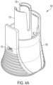
- a shield removal assembly 100 including a retainer (110) and a cap remover (150).
- Retainer (110) is nested within cap remover (150).
- cap remover (150) is flared at a distal end thereof to form an ergonomic gripping surface to allow a user to firmly grip the cap remover.
- Retainer (110) and cap remover (150) can be formed of any rigid material, for example, and without limitation, plastics and the like.
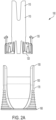
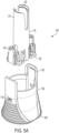
- FIGS. 2A , 2B , and 5A -5C show exploded views of a non-limiting embodiment or aspect of the shield removal assembly described herein.
- Cap remover (150) includes proximal end (155), which is configured to be closest to the housing, and a distal end (160).
- proximal end (155) of cap remover (150) includes two or more arms that engage with a housing (not shown) of an autoinjector.
- the arms of the cap remover (150) include at least one projection or shoulder to allow secure, releasable engagement with the housing of the autoinjector.
- the distal end (160) of cap remover (150) includes at least one opening (162) therethrough.
- cap remover (150) includes in a sidewall thereof at least one opening (170). In non-limiting embodiments or aspects, cap remover (150) includes two openings (170). In non-limiting embodiments or aspects, cap remover (150) includes two openings (170) that are located on opposite sides of the cap remover (150).
- retainer (110) includes proximal (115, closest to the housing) and distal (120) ends.
- proximal end (115) of retainer (110) includes two or more arms that engage with the needle shield (not shown) of an autoinjector.
- the arms of the retainer (110) include at least one projection to allow secure engagement with the needle shield.
- the distal end (120) of retainer (110) includes at least one opening (122) therethrough.
- the distal end (120) of the retainer (110) is configured to abut the distal end (160) of the cap remover (150).
- the opening (162) in the distal end (160) of the cap remover (150) is of a larger diameter than the opening (122) in the distal end (120) of the retainer (110). In non-limiting embodiments or aspects, this difference in diameter allows the retainer (110) to be introduced into the cap remover (150) through the opening (162) in the distal end (160) of the cap remover (150).
- proximal end (115) of retainer (110) can include at least one grasping feature, such as a projection, to allow secure engagement with a needle shield.
- the retainer (110) includes at least one grasping feature (125) at a proximal end (115) thereof.
- the at least one grasping feature can be at least one protrusion (125), and can be configured such that it is capable of gripping a needle shield by a flange thereof.
- the retainer (110) and cap remover (150) of the shield removal assembly (100) are configured or arranged such that the needle shield and/or syringe of an autoinjector (not shown) can be shifted relative to the retainer by introducing a device, such as a tool, through the openings (122, 162) in the distal ends (120, 160) of the retainer (110) and cap remover (150), respectively. Placing a tool through the openings in the cap remover and retainer allows the needle shield and syringe to be displaced proximally, and thus allows for adjustment of the positioning of the projections (125) relative to the needle shield to ensure a secure grip between the retainer (110) and the needle shield.
- a device such as a tool
- the cap remover (150) includes at least one opening (170) in a sidewall thereof.
- the at least one opening (170) is configured to allow at least one radially-extending protrusion (135) on retainer (110) to extend therethrough.
- at least one radially-extending protrusion (135) extends from an arm that extends proximally from the distal end (120) of the retainer (110).
- the at least one radially-extending protrusion (135) is positioned on a main body of the retainer (110).
- a lag arrangement is provided between the cap remover (150) and the retainer (110) during removal of the shield removal assembly (100).
- Retainer (110) is received within cap remover (150) such that at least one protrusion (112) is arranged proximally of at least one shoulder (152) of cap remover (150).
- the at least one protrusion (112) prevents the retainer (110) from being displaced distally out of the cap remover (150), by virtue of engagement with a proximal surface of the at least one shoulder (152).
- the retainer (110) further includes at least one flange (114), arranged distally of the at least one shoulder (152) of the cap remover (150). In this way, the retainer (110) is prevented from being displaced proximally out of the cap remover (150) by virtue of engagement of a proximal surface of the at least one flange (114) with a distal surface of the at least one shoulder (152).
- the longitudinal space between the at least one protrusion (112) and the at least one flange (114) on the retainer (110) results in a predetermined amount of "play" between these components.
- cap remover (150) when the cap remover (150) is pulled distally to remove the shield removal assembly (100) from a drug delivery device to which it is attached, cap remover (150) is pulled a certain distance before the at least one shoulder (152) engages the at least one protrusion (112) of the retainer (110). This results in a lag between the initiation of movement of the cap remover (150) and initiation of movement of the retainer (110).
- cap remover (150) moves sufficiently such that the at least one shoulder (152) engages with the at least one protrusion (112), the retainer (110) begins to be pulled away from the drug delivery device, and, because of the positioning of the at least one projection (125) relative to the needle shield, the needle shield begins to be pulled away from the syringe and needle.
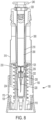
- an autoinjector including a housing, a syringe having a barrel, a needle, and a needle shield, and a shield removal assembly.
- FIGS. 7-9 shown is an autoinjector having a housing, a syringe (200) having a barrel (210) and a needle (220) attached thereto, a removable needle shield (230) configured to at least partially surround the needle (220), and a shield removal assembly (100).
- the autoinjector housing (a lower housing (310) is shown, though it should be understood that autoinjector can include an upper housing, as described below) includes a proximal end and a distal end, where the distal end is open to permit the needle (220) to pass therethrough to allow a substance to be delivered to a user.
- Removable needle shield (230) can include proximal (232) and distal (234) ends.
- removable needle shield (230) is a two-piece needle shield, including an elastomeric inner portion and a rigid outer portion.
- the rigid outer portion at least partially surrounds the elastomeric inner portion of the needle shield (230).
- needle shield (230) includes at least one flange or shoulder (235).
- the at least one flange or shoulder (235) is located on the elastomeric inner portion, for engaging the rigid outer portion.
- needle shield (230) includes at least one complementary grasping feature (233) on the proximal end (232) thereof.
- the at least one complementary grasping feature (233) is configured to be complementary to, and engageable with, the at least one grasping feature (125) of the retainer.
- the at least one complementary grasping feature (233) is the proximal edge of the needle shield (230).
- the elastomeric portion of the needle shield (230) is formed of one or more natural or synthetic rubbers and/or of thermoplastic elastomer, or combinations thereof.
- the rigid outer portion of the needle shield (230) is formed of a rigid plastic. In non-limiting embodiments or aspects, the rigid outer portion is formed of polypropylene.
- Shield removal assembly (100) includes, as described previously, cap remover (150) and retainer (110).
- the cap remover (150) and/or retainer (110) include one or more of the features described above.
- cap remover (150) at least partially surrounds the open distal end of the housing.
- cap remover (150) is not rotatable relative to the housing.
- Autoinjector housing and/or cap remover (150) can include suitable features to prevent rotation of the cap remover (150), and, accordingly, retainer (110) and needle shield (230), relative to the housing and the needle (220), during needle shield (230) removal.
- suitable anti-rotation features include one or more projections, guide channels, and/or shoulders on cap remover (150) and/or housing.
- a method of assembling an autoinjector including a shield removal assembly including the steps of providing a lower housing assembly of an autoinjector, inserting a syringe into the lower assembly, and placing an upper assembly on the lower assembly.
- a lower housing assembly (300) including shield removal assembly (100) engaged therewith, is provided.
- the lower housing assembly (300) includes lower housing (310).
- lower assembly (300) includes a ring (320) at a proximal end thereof.
- the lower housing assembly (300) includes a proximal end and a distal end, the distal end being open to allow a needle of a syringe to pass therethrough, and the proximal end of the lower housing (310) being open to allow a syringe to be inserted into the housing.
- Housing may be formed of any suitable material, including, for example and without limitation, a rigid plastic.
- Lower assembly (300) also includes a shield removal assembly (100).
- Shield removal assembly (100) includes, as described previously, cap remover (150) and retainer (110), each having distal ends (160, 120) having an opening (162, 122) therethrough.
- the cap remover (150) and/or retainer (110) include one or more of the features described above.
- the distal end (120) of the retainer (110) is spaced from the distal end (160) of the cap remover (150).
- a syringe (200) in a second step of the method, is inserted into the lower housing (310).
- the syringe (200) can include a barrel (210) to hold a medicament or other substance therein, a needle (220) arranged at a distal end of the barrel (210), and a removable needle shield (230).
- Syringe (200), barrel (210), needle (220), and needle shield (230) can include one or more of the features described above.
- Syringe barrel (210) can be of any useful size, and can be formed of any useful material, such as glass or plastic.
- syringe (200) is a unitary syringe, and the needle (220) is formed with the syringe barrel (210).
- syringe barrel (210) is not formed with needle (220) therein and, instead, a needle hub (not shown) holds needle (220).
- Syringe needle (220) can be formed of any useful material, and can be of any suitable gauge.
- Needle shield (230) can be a one-piece needle shield formed of an elastomeric material, or a two-piece needle shield having an inner portion formed of an elastomeric material and an outer portion formed of a rigid material. The needle shield (230) at least partially surrounds the needle (220).
- syringe (200) includes a flange (240) at a proximal end thereof. At the conclusion of the second step, the distal end (120) of the retainer (110) remains longitudinally spaced from the distal end (160) of the cap remover (150).
- the step of inserting the syringe (200) includes moving the syringe (200) towards the distal end of the housing (310), preferably such that the at least one grasping feature (125) is spaced longitudinally from the proximal end of the needle shield.
- the at least one grasping feature (125) is more proximal than in its final position (shown in FIG. 9 ). In this position, the distal end (234) of the syringe flange abuts the ring (320). In this position, the proximal end (115) of the retainer (110) contacts the syringe barrel (210).
- the distal end (120) of the retainer (110) is maintained proximally with respect to the distal end (160) of the cap remover (150), such that the distal end (120) of the retainer (110) is longitudinally spaced from the distal end (160) of the cap remover (150).
- a tool (not shown) is inserted within the opening (162) of the cap remover (150). This tool can be used to push the retainer (110) proximally, such that the distal end (120) of the retainer (110) is longitudinally spaced from the distal end (160) of the cap remover (150).
- the proximal end (115) of the retainer (110) includes at least one grasping feature, such as projections (125), and the projections (125) contact the syringe barrel (210) proximally of the distal end of the syringe barrel (210). In this way, the retainer (110) is in an "overstroked" position, where the at least one grasping feature (125) is located too far proximally of the needle shield (230) ( FIG. 7 ).
- the needle shield (230) includes at least one flange or shoulder (235), and the proximal end (115) of the retainer (110) includes at least one grasping feature (125), and the at least one grasping feature (125) contacts the syringe barrel (210) proximally of the at least one flange or shoulder (235).
- a third step of the method of assembling the syringe includes, after inserting the syringe (200) into the lower housing (310), moving the syringe (200) proximally.
- moving the syringe (200) proximally within the lower housing (310) is achieved by inserting a device through the at least one opening (162, 122) in the distal ends (160, 120) of the cap remover (150) and retainer (110), and applying pressure to urge the syringe (200) proximally.
- moving the syringe (200) proximally within the lower housing (310) is achieved by inserting a device through the at least one opening (162, 122) in the distal ends (160, 120) of the cap remover (150) and retainer (110), and applying pressure to urge the syringe (200) proximally.
- the at least one grasping feature (125) engages the at least one complementary grasping feature (233) of the needle shield (230), the distal end (120) of the retainer (110) is longitudinally spaced from the distal end (160) of the cap remover (150), and the syringe flange (240) is longitudinally spaced from the ring (320).
- the method includes a fourth step of placing an upper assembly (not shown), including an upper housing, on the lower assembly.
- upper assembly and upper housing can be formed of any suitable material, including, for example and without limitation, a rigid plastic.
- the step of placing the upper assembly on the lower assembly causes the syringe to move distally, such that the syringe flange (240) abuts the ring (320).
- distal end (120) of retainer (110) falls or is otherwise displaced towards the distal end (160) of the cap remover (150), such that the distal end (120) of the retainer (110) abuts the distal end (160) of the cap remover (150).
- the gap between the at least one protrusion (112) of the retainer (110) and the at least one shoulder (152) of the cap remover (150) causes a lag between the initiation of longitudinal movement of the cap remover (150) away from the lower housing assembly (300) and the initiation of longitudinal movement of the retainer (110) away from the lower housing assembly (300).
Landscapes
- Health & Medical Sciences (AREA)
- Vascular Medicine (AREA)
- Engineering & Computer Science (AREA)
- Anesthesiology (AREA)
- Biomedical Technology (AREA)
- Heart & Thoracic Surgery (AREA)
- Hematology (AREA)
- Life Sciences & Earth Sciences (AREA)
- Animal Behavior & Ethology (AREA)
- General Health & Medical Sciences (AREA)
- Public Health (AREA)
- Veterinary Medicine (AREA)
- Infusion, Injection, And Reservoir Apparatuses (AREA)
Claims (15)
- Schutzentfernungsbaugruppe (100) für einen Autoinjektor, umfassend einen Spritzenkörper, eine Nadel und einen Nadelschutz, der die Nadel mindestens teilweise umgibt, wobei die Schutzentfernungsbaugruppe Folgendes umfasst:einen Kappenentferner (150), der so eingerichtet ist, dass er von einem Benutzer gegriffen werden kann und ein proximales Ende (155) und ein distales Ende (160) aufweist, wobei das distale Ende (160) des Kappenentferners (150) mindestens eine Öffnung (162) darin umfasst; undeine Halterung (110), die innerhalb des Kappenentferners (150) aufgenommen ist und ein proximales Ende (115) und ein distales Ende (120) umfasst, wobei die Halterung (110) mindestens ein Greifelement (125) umfasst, das so eingerichtet ist, dass es mindestens ein ergänzendes Greifelement des Nadelschutzes einrastet, und das distale Ende (120) eine Öffnung (122) darin umfasst;wobei die Schutzentfernungsbaugruppe (100) so eingerichtet ist, dass der Nadelschutz des Autoinjektors durch die Schutzentfernungsbaugruppe (100) von einer ersten Position vorgeschoben werden kann, in der das mindestens eine Greifelement (125) längs beabstandet ist und sich proximal des mindestens einen ergänzenden Greifelements des Nadelschutzes befindet, bis zu einer zweiten Position, in der das mindestens eine Greifelement (125) das mindestens eine ergänzende Greifelement des Nadelschutzes einrastet;wobei die Halterung (110) mindestens einen radial erstreckbaren Vorsprung (135) umfasst, und der Kappenentferner (150) mindestens ein Fenster (170) umfasst, das so eingerichtet ist, dass es den radial erstreckbaren Vorsprung (135) aufnimmt, unddadurch gekennzeichnet, dass die Halterung relativ zum Kappenentferner axial beweglich ist,und dass die Halterung mindestens einen Vorsprung (112) umfasst; und der Kappenentferner (150) mindestens eine Schulter (152) umfasst, die längs von dem mindestens einen Vorsprung (112) der Halterung (110) beabstandet ist, so dass der Kappenentferner (150) längs um einen bestimmten Abstand von der Spritze wegbewegt wird, bevor die mindestens eine Schulter (152) den mindestens einen Vorsprung (112) einrastet.
- Schutzentfernungsbaugruppe nach Anspruch 1, wobei das mindestens eine Greifelement mindestens einen Vorsprung umfasst und das mindestens eine ergänzende Greifelement einen proximalen Rand des Nadelschutzes umfasst.
- Schutzentfernungsbaugruppe (100) nach einem der Ansprüche 1 bis 2, wobei sich das mindestens eine Greifelement (125) am proximalen Ende (115) der Halterung (110) befindet, wobei die Schutzentfernungsbaugruppe (100) so eingerichtet ist, dass der Nadelschutz des Autoinjektors aus einer ersten Position, in der das proximale Ende des Nadelschutzes längs von dem mindestens einen Greifelement (125) der Halterung (110) beabstandet ist, durch die Schutzentfernungsbaugruppe (100) vorgeschoben werden kann in eine zweite Position, in der das proximale Ende des Nadelschutzes an dem mindestens einen Greifelement (125) der Halterung (110) anliegt.
- Schutzentfernungsbaugruppe (100) nach einem der Ansprüche 1 bis 3, wobei die Öffnung im distalen Ende (160) des Kappenentferners (150) einen größeren Durchmesser hat als die Öffnung im distalen Ende (120) der Halterung (110).
- Schutzentfernungsbaugruppe (100) nach einem der Ansprüche 1 bis 4, wobei nach dem Zusammenbau das distale Ende (120) der Halterung (110) in Richtung des distalen Endes (160) des Kappenentferners (150) fällt oder anderweitig verschoben wird, so dass das distale Ende (120) der Halterung (110) am distalen Ende (160) des Kappenentferners (150) anliegt.
- Autoinjektor, umfassend:ein Gehäuse, das ein proximales Ende, ein offenes distales Ende aufweist und eine Längsachse definiert;eine Spritze (200), die innerhalb des Gehäuses gehalten wird und einen Zylinder (210) aufweist;eine Nadel (220), die an einem distalen Ende des Spritzenkörpers (210) befestigt ist;einen abnehmbaren Nadelschutz (230), der ein proximales Ende (232) und ein distales Ende aufweist, wobei der Nadelschutz (230) so eingerichtet ist, dass er die Nadel (220) mindestens teilweise umgibt; undeine Schutzentfernungsbaugruppe (100) nach einem der Ansprüche 1 bis 5.
- Autoinjektor nach Anspruch 6, wobei der Kappenentferner (150) relativ zum Gehäuse nicht drehbar ist.
- Verfahren zur Montage eines Autoinjektors, umfassend:
Bereitstellung einer unteren Baugruppe (300), wobei die untere Baugruppe umfasst:ein unteres Gehäuse (310), das ein proximales Ende und ein distales Ende aufweist und eine Längsachse definiert;und einer Schutzentfernungsbaugruppe (100) nach einem der Ansprüche 1 bis 5, die am distalen Ende des unteren Gehäuses (310) angeordnet ist, wobei die mindestens eine Öffnung (122) der Halterung in einer anfänglichen Einrichtung von dem distalen Ende (160) des Kappenentferners (150) beabstandet ist;Einsetzen einer Spritze (200) in die untere Baugruppe, wobei die Spritze (200) Folgendes umfasst:einen Zylinder (210) mit einem proximalen Ende und einem distalen Ende;eine Nadel (220), die am distalen Ende des Zylinders (210) angeordnet ist; undeinen abnehmbaren Nadelschutz (230), der ein proximales Ende (232) aufweist, das mindestens ein ergänzendes Greifelement (233) und ein distales Ende (234) umfasst, wobei der Nadelschutz (230) so eingerichtet ist, dass er die Nadel (220) zumindest teilweise umgibt,wobei der Schritt des Einsetzens das Bewegen der Spritze (200) in Richtung des distalen Endes des unteren Gehäuses (310) entlang der Längsachse umfasst, so dass das mindestens ein Greifelement (125) der Halterung (110) längs beabstandet ist und sich proximal des mindestens einen ergänzenden Greifelements (233) des Nadelschutzes (230) befindet; undAufsetzen einer oberen Baugruppe, die ein oberes Gehäuse umfasst, auf die untere Baugruppe (300). - Verfahren nach Anspruch 8, wobei das mindestens eine Greifelement (125) der Halterung (110) ein Vorsprung (125) ist, der so eingerichtet ist, dass er einen proximalen Rand des Nadelschutzes (230) einrastet, und wobei der Schritt des Einsetzens der Spritze (200) in die untere Baugruppe das distale Einführen der Spritze (200) umfasst, so dass der mindestens eine Vorsprung (125) proximal positioniert ist und längs vom proximalen Rand des Nadelschutzes (230) beabstandet ist.
- Verfahren nach Anspruch 8 oder Anspruch 9, ferner umfassend einen Schritt, bei dem nach dem Einsetzen der Spritze (200) in die untere Baugruppe (300) die Spritze (200) proximal so gedrückt wird, dass das mindestens eine Greifelement (125) den proximalen Rand des Nadelschutzes einrastet.
- Verfahren nach Anspruch 10, wobei der Schritt des proximalen Eindringens der Spritze (200) das Einsetzen einer Vorrichtung durch die mindestens eine Öffnung (162) in das distale Ende (160) des Kappenentferners (150) und die Öffnung (122) in das distale Ende (120) der Halterung (110) umfasst, um die Spritze (200) proximal einzudringen.
- Verfahren nach einem der Ansprüche 9 bis 11, wobei das proximale Ende des Spritzenkörpers (210) einen Flansch (240) und das proximale Ende des unteren Gehäuses (310) einen Ring (320) umfasst.
- Verfahren nach Anspruch 12, wobei nach dem Einsetzen der Spritze (200) der Spritzenflansch (240) am Ring (320) anliegt.
- Verfahren nach Anspruch 13, ferner umfassend, nach dem Einsetzen der Spritze (200) in die untere Baugruppe (300), einen Schritt des proximalen Eindringens der Spritze (200), und wobei nach dem Schritt des proximalen Eindringens der Spritze (200) der Spritzenflansch (240) längs vom Ring (320) des Nadelschutzes beabstandet ist.
- Verfahren nach einem der Ansprüche 8 bis 14, wobei nach dem Zusammenbau das distale Ende (120) der Halterung (110) in Richtung des distalen Endes (160) des Kappenentferners (150) fällt oder anderweitig verschoben wird, sodass das distale Ende (120) der Halterung (110) am distalen Ende (160) des Kappenentferners (150) anliegt.
Applications Claiming Priority (2)
| Application Number | Priority Date | Filing Date | Title |
|---|---|---|---|
| EP19305228 | 2019-02-26 | ||
| PCT/EP2020/055012 WO2020173998A1 (en) | 2019-02-26 | 2020-02-26 | Rigid needle shield remover for autoinjector |
Publications (3)
| Publication Number | Publication Date |
|---|---|
| EP3930792A1 EP3930792A1 (de) | 2022-01-05 |
| EP3930792B1 true EP3930792B1 (de) | 2025-04-23 |
| EP3930792C0 EP3930792C0 (de) | 2025-04-23 |
Family
ID=65766939
Family Applications (1)
| Application Number | Title | Priority Date | Filing Date |
|---|---|---|---|
| EP20706285.2A Active EP3930792B1 (de) | 2019-02-26 | 2020-02-26 | Nadelschutzentferner für autoinjektor |
Country Status (9)
| Country | Link |
|---|---|
| US (1) | US20220105278A1 (de) |
| EP (1) | EP3930792B1 (de) |
| JP (1) | JP7265026B2 (de) |
| KR (1) | KR102607293B1 (de) |
| CN (2) | CN116531614A (de) |
| AU (1) | AU2020227896B2 (de) |
| BR (1) | BR112021016311A2 (de) |
| MX (1) | MX2021009666A (de) |
| WO (1) | WO2020173998A1 (de) |
Families Citing this family (5)
| Publication number | Priority date | Publication date | Assignee | Title |
|---|---|---|---|---|
| CA3228677A1 (en) | 2021-08-24 | 2023-03-02 | Damien Marechal | Connected drug delivery device |
| EP4285965A1 (de) * | 2022-06-02 | 2023-12-06 | Becton, Dickinson and Company | Starrer nadelschutzentferner mit anschlussbestätigung für autoinjektor |
| EP4299092B1 (de) | 2022-07-01 | 2025-03-19 | Becton Dickinson France | Kappe zum entfernen eines nadelschutzes, der an einem medizinischen behälter befestigt ist, der im körper eines autoinjektors angeordnet ist |
| WO2024056412A1 (en) * | 2022-09-13 | 2024-03-21 | Shl Medical Ag | Medicament delivery system |
| EP4445929A1 (de) | 2023-04-14 | 2024-10-16 | Becton, Dickinson and Company | Verbundene arzneimittelabgabevorrichtung |
Family Cites Families (26)
| Publication number | Priority date | Publication date | Assignee | Title |
|---|---|---|---|---|
| GB9506087D0 (en) * | 1995-03-24 | 1995-05-10 | Owen Mumford Ltd | Improvements relating to medical injection devices |
| JP2002510534A (ja) | 1998-04-01 | 2002-04-09 | ジレ テック プロプライアタリー リミテッド | 注射針保護装置 |
| GB2438593B (en) * | 2006-06-01 | 2011-03-30 | Cilag Gmbh Int | Injection device (cap removal feature) |
| WO2009040602A1 (en) * | 2007-09-25 | 2009-04-02 | Becton Dickinson France | Autoinject0r with deactivating means moveable by a safety shield |
| US8048029B2 (en) * | 2008-06-20 | 2011-11-01 | West Pharmaceutical Services, Inc. | Injector apparatus |
| GB2478349A (en) * | 2010-03-05 | 2011-09-07 | Owen Mumford Ltd | Injection device having projections reducing the diameter of the syringe passage |
| RU2695566C2 (ru) * | 2011-01-24 | 2019-07-24 | Эббви Байотекнолоджи Лтд. | Снятие кожухов иглы со шприцов и автоматических инъекционных устройств |
| BR112014000197B1 (pt) * | 2011-07-05 | 2021-03-23 | Shl Medical Ag | Conjunto removedor de revestimento de agulha |
| US9233212B2 (en) * | 2011-10-17 | 2016-01-12 | Shl Group Ab | Device for removing delivery member shields |
| EP2926861B1 (de) * | 2012-03-14 | 2019-01-30 | SHL Medical AG | Medikamentenabgabevorrichtung |
| CN104968381B (zh) | 2012-12-21 | 2017-07-04 | 卡贝欧洲有限公司 | 药物输送设备 |
| CA2903484C (en) * | 2013-03-13 | 2019-01-08 | Antares Pharma, Inc. | Push button safety injector |
| DK2978478T3 (da) | 2013-03-25 | 2021-08-02 | Shl Medical Ag | Beskyttelseshætte til en medikamentafgivelsesanordning |
| EP2826509A1 (de) * | 2013-07-18 | 2015-01-21 | Sanofi-Aventis Deutschland GmbH | Nadelschutzentferner |
| EP2878321A1 (de) * | 2013-11-28 | 2015-06-03 | Sanofi-Aventis Deutschland GmbH | Nadelsicherheitsvorrichtung und Arzneimittelabgabevorrichtung |
| EP2923716A1 (de) * | 2014-03-28 | 2015-09-30 | Sanofi-Aventis Deutschland GmbH | Kappe mit Hüllenentfernungsmechanismus |
| EP3204093B1 (de) * | 2014-10-08 | 2018-09-19 | Carebay Europe Ltd. | Medikamentenverabreichungsvorrichtung |
| TW201707741A (zh) * | 2015-06-03 | 2017-03-01 | 賽諾菲阿凡提斯德意志有限公司 | 針頭護罩之抓握器、蓋子、自動注射器及製造抓握器之方法 |
| KR102418571B1 (ko) | 2015-07-30 | 2022-07-08 | 엘지디스플레이 주식회사 | 감마 보정 회로 및 그 구동방법과 그를 이용한 표시 장치 |
| US10335553B2 (en) * | 2016-06-13 | 2019-07-02 | Shl Medical Ag | Cap assembly for a medicament delivery device |
| EP3474928A4 (de) * | 2016-06-22 | 2020-02-26 | Antares Pharma, Inc. | Nadelschutzentferner |
| US11077258B2 (en) * | 2016-10-13 | 2021-08-03 | Shl Medical Ag | Sub-assembly for a medicament delivery device |
| EP3320932A1 (de) * | 2016-11-15 | 2018-05-16 | Carebay Europe Ltd. | Medikamentenabgabevorrichtung mit einer kappenanordnung |
| US10828425B2 (en) * | 2017-06-23 | 2020-11-10 | Shl Medical Ag | Needle shield remover and a medicament delivery device comprising the needle shield remover |
| LT3801694T (lt) * | 2018-06-08 | 2025-12-10 | Antares Pharma, Inc. | Automatinio įterpimo injektorius |
| EP3695863A1 (de) * | 2019-02-15 | 2020-08-19 | TecPharma Licensing AG | Modularer spritzenhalter und spritzenmontageverfahren |
-
2020
- 2020-02-26 BR BR112021016311-5A patent/BR112021016311A2/pt unknown
- 2020-02-26 WO PCT/EP2020/055012 patent/WO2020173998A1/en not_active Ceased
- 2020-02-26 KR KR1020217030633A patent/KR102607293B1/ko active Active
- 2020-02-26 MX MX2021009666A patent/MX2021009666A/es unknown
- 2020-02-26 AU AU2020227896A patent/AU2020227896B2/en active Active
- 2020-02-26 CN CN202310662131.5A patent/CN116531614A/zh active Pending
- 2020-02-26 US US17/425,958 patent/US20220105278A1/en active Pending
- 2020-02-26 CN CN202080016510.1A patent/CN113507949B/zh active Active
- 2020-02-26 JP JP2021549996A patent/JP7265026B2/ja active Active
- 2020-02-26 EP EP20706285.2A patent/EP3930792B1/de active Active
Also Published As
| Publication number | Publication date |
|---|---|
| CN113507949A (zh) | 2021-10-15 |
| BR112021016311A2 (pt) | 2021-10-13 |
| AU2020227896A1 (en) | 2021-09-16 |
| KR102607293B1 (ko) | 2023-11-29 |
| JP7265026B2 (ja) | 2023-04-25 |
| MX2021009666A (es) | 2021-09-08 |
| WO2020173998A1 (en) | 2020-09-03 |
| CN113507949B (zh) | 2023-06-20 |
| KR20210131397A (ko) | 2021-11-02 |
| EP3930792A1 (de) | 2022-01-05 |
| JP2022522173A (ja) | 2022-04-14 |
| CN116531614A (zh) | 2023-08-04 |
| CA3127415A1 (en) | 2020-09-03 |
| AU2020227896B2 (en) | 2022-09-08 |
| US20220105278A1 (en) | 2022-04-07 |
| EP3930792C0 (de) | 2025-04-23 |
Similar Documents
| Publication | Publication Date | Title |
|---|---|---|
| EP3930792B1 (de) | Nadelschutzentferner für autoinjektor | |
| US12569625B2 (en) | Rigid needle shield remover with drop test feature for autoinjector | |
| US11426531B2 (en) | Medical injector cap remover | |
| CA3127415C (en) | Rigid needle shield remover for autoinjector | |
| US20230414874A1 (en) | Rigid Needle Shield Remover with Connection Confirmation Feature for Autoinjector | |
| RU2854207C2 (ru) | Устройство для съема жесткого игольного чехла для автоинъектора | |
| RU2776332C1 (ru) | Устройство для съема жесткого игольного чехла для автоинъектора | |
| RU2780506C1 (ru) | Устройство для удаления жесткого защитного колпачка для иглы с приспособлением для испытания на ударную нагрузку для шприц-ручки |
Legal Events
| Date | Code | Title | Description |
|---|---|---|---|
| STAA | Information on the status of an ep patent application or granted ep patent |
Free format text: STATUS: UNKNOWN |
|
| STAA | Information on the status of an ep patent application or granted ep patent |
Free format text: STATUS: THE INTERNATIONAL PUBLICATION HAS BEEN MADE |
|
| PUAI | Public reference made under article 153(3) epc to a published international application that has entered the european phase |
Free format text: ORIGINAL CODE: 0009012 |
|
| STAA | Information on the status of an ep patent application or granted ep patent |
Free format text: STATUS: REQUEST FOR EXAMINATION WAS MADE |
|
| 17P | Request for examination filed |
Effective date: 20210915 |
|
| AK | Designated contracting states |
Kind code of ref document: A1 Designated state(s): AL AT BE BG CH CY CZ DE DK EE ES FI FR GB GR HR HU IE IS IT LI LT LU LV MC MK MT NL NO PL PT RO RS SE SI SK SM TR |
|
| DAV | Request for validation of the european patent (deleted) | ||
| DAX | Request for extension of the european patent (deleted) | ||
| STAA | Information on the status of an ep patent application or granted ep patent |
Free format text: STATUS: EXAMINATION IS IN PROGRESS |
|
| 17Q | First examination report despatched |
Effective date: 20230418 |
|
| GRAP | Despatch of communication of intention to grant a patent |
Free format text: ORIGINAL CODE: EPIDOSNIGR1 |
|
| STAA | Information on the status of an ep patent application or granted ep patent |
Free format text: STATUS: GRANT OF PATENT IS INTENDED |
|
| INTG | Intention to grant announced |
Effective date: 20241210 |
|
| GRAS | Grant fee paid |
Free format text: ORIGINAL CODE: EPIDOSNIGR3 |
|
| GRAA | (expected) grant |
Free format text: ORIGINAL CODE: 0009210 |
|
| STAA | Information on the status of an ep patent application or granted ep patent |
Free format text: STATUS: THE PATENT HAS BEEN GRANTED |
|
| AK | Designated contracting states |
Kind code of ref document: B1 Designated state(s): AL AT BE BG CH CY CZ DE DK EE ES FI FR GB GR HR HU IE IS IT LI LT LU LV MC MK MT NL NO PL PT RO RS SE SI SK SM TR |
|
| REG | Reference to a national code |
Ref country code: GB Ref legal event code: FG4D |
|
| REG | Reference to a national code |
Ref country code: CH Ref legal event code: EP |
|
| REG | Reference to a national code |
Ref country code: DE Ref legal event code: R096 Ref document number: 602020049893 Country of ref document: DE |
|
| REG | Reference to a national code |
Ref country code: IE Ref legal event code: FG4D |
|
| U01 | Request for unitary effect filed |
Effective date: 20250509 |
|
| U07 | Unitary effect registered |
Designated state(s): AT BE BG DE DK EE FI FR IT LT LU LV MT NL PT RO SE SI Effective date: 20250516 |
|
| PG25 | Lapsed in a contracting state [announced via postgrant information from national office to epo] |
Ref country code: ES Free format text: LAPSE BECAUSE OF FAILURE TO SUBMIT A TRANSLATION OF THE DESCRIPTION OR TO PAY THE FEE WITHIN THE PRESCRIBED TIME-LIMIT Effective date: 20250423 |
|
| PG25 | Lapsed in a contracting state [announced via postgrant information from national office to epo] |
Ref country code: GR Free format text: LAPSE BECAUSE OF FAILURE TO SUBMIT A TRANSLATION OF THE DESCRIPTION OR TO PAY THE FEE WITHIN THE PRESCRIBED TIME-LIMIT Effective date: 20250724 Ref country code: NO Free format text: LAPSE BECAUSE OF FAILURE TO SUBMIT A TRANSLATION OF THE DESCRIPTION OR TO PAY THE FEE WITHIN THE PRESCRIBED TIME-LIMIT Effective date: 20250723 |
|
| PG25 | Lapsed in a contracting state [announced via postgrant information from national office to epo] |
Ref country code: PL Free format text: LAPSE BECAUSE OF FAILURE TO SUBMIT A TRANSLATION OF THE DESCRIPTION OR TO PAY THE FEE WITHIN THE PRESCRIBED TIME-LIMIT Effective date: 20250423 |
|
| PG25 | Lapsed in a contracting state [announced via postgrant information from national office to epo] |
Ref country code: HR Free format text: LAPSE BECAUSE OF FAILURE TO SUBMIT A TRANSLATION OF THE DESCRIPTION OR TO PAY THE FEE WITHIN THE PRESCRIBED TIME-LIMIT Effective date: 20250423 |
|
| PG25 | Lapsed in a contracting state [announced via postgrant information from national office to epo] |
Ref country code: RS Free format text: LAPSE BECAUSE OF FAILURE TO SUBMIT A TRANSLATION OF THE DESCRIPTION OR TO PAY THE FEE WITHIN THE PRESCRIBED TIME-LIMIT Effective date: 20250723 |
|
| PG25 | Lapsed in a contracting state [announced via postgrant information from national office to epo] |
Ref country code: IS Free format text: LAPSE BECAUSE OF FAILURE TO SUBMIT A TRANSLATION OF THE DESCRIPTION OR TO PAY THE FEE WITHIN THE PRESCRIBED TIME-LIMIT Effective date: 20250823 |
|
| PG25 | Lapsed in a contracting state [announced via postgrant information from national office to epo] |
Ref country code: SM Free format text: LAPSE BECAUSE OF FAILURE TO SUBMIT A TRANSLATION OF THE DESCRIPTION OR TO PAY THE FEE WITHIN THE PRESCRIBED TIME-LIMIT Effective date: 20250423 |
|
| PG25 | Lapsed in a contracting state [announced via postgrant information from national office to epo] |
Ref country code: CZ Free format text: LAPSE BECAUSE OF FAILURE TO SUBMIT A TRANSLATION OF THE DESCRIPTION OR TO PAY THE FEE WITHIN THE PRESCRIBED TIME-LIMIT Effective date: 20250423 |
|
| PG25 | Lapsed in a contracting state [announced via postgrant information from national office to epo] |
Ref country code: SK Free format text: LAPSE BECAUSE OF FAILURE TO SUBMIT A TRANSLATION OF THE DESCRIPTION OR TO PAY THE FEE WITHIN THE PRESCRIBED TIME-LIMIT Effective date: 20250423 |
|
| U20 | Renewal fee for the european patent with unitary effect paid |
Year of fee payment: 7 Effective date: 20260121 |
|
| PLBE | No opposition filed within time limit |
Free format text: ORIGINAL CODE: 0009261 |
|
| STAA | Information on the status of an ep patent application or granted ep patent |
Free format text: STATUS: NO OPPOSITION FILED WITHIN TIME LIMIT |
|
| REG | Reference to a national code |
Ref country code: CH Ref legal event code: L10 Free format text: ST27 STATUS EVENT CODE: U-0-0-L10-L00 (AS PROVIDED BY THE NATIONAL OFFICE) Effective date: 20260304 |
|
| 26N | No opposition filed |
Effective date: 20260126 |
|
| PGFP | Annual fee paid to national office [announced via postgrant information from national office to epo] |
Ref country code: GB Payment date: 20260121 Year of fee payment: 7 |