EP3930593B1 - Hämostatische vorrichtungen mit gefalteten ballonanordnungen - Google Patents
Hämostatische vorrichtungen mit gefalteten ballonanordnungen Download PDFInfo
- Publication number
- EP3930593B1 EP3930593B1 EP20766953.2A EP20766953A EP3930593B1 EP 3930593 B1 EP3930593 B1 EP 3930593B1 EP 20766953 A EP20766953 A EP 20766953A EP 3930593 B1 EP3930593 B1 EP 3930593B1
- Authority
- EP
- European Patent Office
- Prior art keywords
- balloon assembly
- balloon
- perimeter
- channel
- chamber
- Prior art date
- Legal status (The legal status is an assumption and is not a legal conclusion. Google has not performed a legal analysis and makes no representation as to the accuracy of the status listed.)
- Active
Links
Images




Classifications
-
- A—HUMAN NECESSITIES
- A61—MEDICAL OR VETERINARY SCIENCE; HYGIENE
- A61B—DIAGNOSIS; SURGERY; IDENTIFICATION
- A61B17/00—Surgical instruments, devices or methods
- A61B17/12—Surgical instruments, devices or methods for ligaturing or otherwise compressing tubular parts of the body, e.g. blood vessels or umbilical cord
- A61B17/132—Tourniquets
- A61B17/1322—Tourniquets comprising a flexible encircling member
- A61B17/1325—Tourniquets comprising a flexible encircling member with means for applying local pressure
-
- A—HUMAN NECESSITIES
- A61—MEDICAL OR VETERINARY SCIENCE; HYGIENE
- A61B—DIAGNOSIS; SURGERY; IDENTIFICATION
- A61B17/00—Surgical instruments, devices or methods
- A61B17/12—Surgical instruments, devices or methods for ligaturing or otherwise compressing tubular parts of the body, e.g. blood vessels or umbilical cord
- A61B17/132—Tourniquets
- A61B17/135—Tourniquets inflatable
-
- A—HUMAN NECESSITIES
- A61—MEDICAL OR VETERINARY SCIENCE; HYGIENE
- A61B—DIAGNOSIS; SURGERY; IDENTIFICATION
- A61B17/00—Surgical instruments, devices or methods
- A61B2017/00526—Methods of manufacturing
-
- A—HUMAN NECESSITIES
- A61—MEDICAL OR VETERINARY SCIENCE; HYGIENE
- A61B—DIAGNOSIS; SURGERY; IDENTIFICATION
- A61B17/00—Surgical instruments, devices or methods
- A61B17/12—Surgical instruments, devices or methods for ligaturing or otherwise compressing tubular parts of the body, e.g. blood vessels or umbilical cord
- A61B2017/12004—Surgical instruments, devices or methods for ligaturing or otherwise compressing tubular parts of the body, e.g. blood vessels or umbilical cord for haemostasis, for prevention of bleeding
-
- A—HUMAN NECESSITIES
- A61—MEDICAL OR VETERINARY SCIENCE; HYGIENE
- A61M—DEVICES FOR INTRODUCING MEDIA INTO, OR ONTO, THE BODY; DEVICES FOR TRANSDUCING BODY MEDIA OR FOR TAKING MEDIA FROM THE BODY; DEVICES FOR PRODUCING OR ENDING SLEEP OR STUPOR
- A61M39/00—Tubes, tube connectors, tube couplings, valves, access sites or the like, specially adapted for medical use
- A61M39/10—Tube connectors; Tube couplings
- A61M2039/1094—Tube connectors; Tube couplings at least partly incompatible with standard connectors, e.g. to prevent fatal mistakes in connection
Definitions
- hemostasis devices After a surgical procedure involving arterial or venous access, it may be desirable or necessary to apply pressure to the vascular access site to promote hemostasis.
- Some existing hemostasis devices use one or more inflatable balloons to apply pressure to the access site. In some instances, these balloons have experienced failures.
- Some existing hemostasis devices may also be time-consuming and expensive to construct. Accordingly, there is a need for hemostasis devices that address these and other drawbacks of the prior art.
- Peripheral vascular interventions are commonly used to attempt to clear occlusions from, or surgically introduce stents into, vascular pathways. For example, antegrade crossing via the radial artery in a patient's wrist is common, and various retrograde approaches upwardly from below a patient's knee are also established procedures. After such a procedure, the vascular (i.e. , either arterial or venous) access site is typically closed through application of pressure to encourage hemostasis.
- Hemostasis devices that are wrapped around a patient's limb at a site on the limb where bleeding is to be stopped, and which include one or more inflatable balloons or bladders that target pressure at a vascular access site, are known in the art. Multiple embodiments of one such hemostasis device and methods of using such devices are described in U.S. Patent No. 7,498,477 . Additional embodiments of such hemostasis devices and methods of using same are described in U.S. Patent Application No. 16/288,303, filed February 28, 2019 . It should be understood that the devices and methods taught herein could be used or adapted for use with any of the hemostasis devices taught in the references noted above in this paragraph.
- such hemostasis devices generally include a rigid member (e.g., a curved plate that slips into a band) and at least one inflatable balloon that, when inflated, expands in a direction away from the rigid member and presses into a targeted location on a patient's limb or other body part, thereby promoting hemostasis.
- a rigid member e.g., a curved plate that slips into a band
- at least one inflatable balloon that, when inflated, expands in a direction away from the rigid member and presses into a targeted location on a patient's limb or other body part, thereby promoting hemostasis.
- Many of these devices have a dual-balloon design including a connection port that connects the chambers of the two balloons in fluid-flow connection, such that inflating one balloon will cause the fluid (e.g., air) to flow through the connection port and fill the other balloon.
- connection ports are typically made via radio frequency (“RF”) welding or bonding between faces of the adjacent balloons
- connection ports can fail, thus causing the balloon assembly of the hemostasis device to fail to properly inflate.
- the connection port design also requires multiple manufacturing steps and costly and time-consuming manual placement of components during the construction process. Accordingly, there is a need for improved balloon assembly structures and methods of constructing same.
- the present invention describes various embodiments of improved balloon assembly structures, each of which omit the connection port between the balloons.
- Several of these embodiments are formed of two or more layers of material (e.g., vinyl or PVC) connected together via a single welded perimeter and then folded to form a balloon assembly that includes both the large balloon and small balloon at the same time with an open air channel between the two sections.
- the two or more balloon chambers and the air channel that connects between the balloon chambers collectively form a contiguous air chamber, with each component of the contiguous air chamber having been at least partially formed by a single welding step.
- a plurality of balloons are formed and a multi-output connector splits the inflation tubing into the appropriate number of output connection tubes, each of which is separately routed into one of the plurality of balloons.
- significantly fewer manufacturing steps are needed, placement of the components of the balloon assembly is simpler and more automatable, and the relatively-weak connection port is eliminated.
- FIGS. 1-23 various embodiments of balloon assemblies for hemostasis devices will be shown and described in detail.
- the hemostasis devices shown in the Figures are generally designed to be wrapped and secured in place around the arm 2 of a patient near the wrist to encourage hemostasis of the radial artery, as would be understood by a person having ordinary skill in the art.
- the concepts discussed in the present invention have applicability to other hemostasis devices that may be employed elsewhere on a patient's body, for example on any portion of any limb or the torso, neck, or head, and could be used for either arterial or venous hemostasis applications.
- the balloon assemblies according to the present invention be substantially transparent to permit visibility of the vascular access site (both for placement and for monitoring of complications), in alternative embodiments these balloon assemblies may be partially or entirely opaque.
- FIG. 1 is a partial perspective view of a hemostasis device 10 including a balloon assembly 16 according to the prior art, in an uninflated state.
- FIG. 2 shows this balloon assembly 16 by itself in an uninflated state.
- the balloon assembly 16 is attached to an interior side 13 of a band 12 that faces a patient's arm 2 when worn, the band 12 further comprising an an exterior side 14 opposing the interior side 13 and an insert plate 15 inserted within layers (not labeled) of the band 12.
- the balloon assembly 16 comprises a small balloon 18 that is attached to the interior side 13 of the band 12 via an attachment hinge 21 and a large balloon 24 that is attached to the interior side 13 of the band 12 via an attachment hinge 25.
- connection tubing 22 enters the balloon assembly 16 via an inlet 20, and a connection port 26 is formed between the small balloon 18 and large balloon 24 such that air entering the balloon assembly 16 via the connection tubing 22 can freely travel between the balloons 18,24 via the connection port 26.
- connection port 26 is typically RF welded and is subject to occasional failure when the balloon assembly 16 is inflated (as shown in FIG. 3 ).
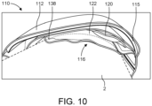
- FIGS. 4-10 show various views of a balloon assembly 116 according to the present invention
- FIGS. 4 and 8-10 show the balloon assembly 116 attached to a hemostasis device 110 according to the present invention.
- FIGS. 4-10 show a "reverse end-fold" design for a balloon assembly 116 which has a single, welded outer perimeter 126 and a single, welded inner perimeter 128 around which a pair of air channels 134a,134b are formed.
- both perimeters 126,128 are formed by laser welding the material layers together, but other construction methods are possible for connecting the material layers of the balloon assembly 116, for example but not limited to RF welding or gluing.
- a cutout 130 is made within the inner perimeter 128 after it has been formed so that the channels 134a,134b are separate portions which are located on opposite sides of the cutout 130.
- the cutout 130 may be omitted so that the inner perimeter 128 surrounds a fully-welded region of two or more layers of material.
- the balloon assembly 116 is fully constructed by being folded about the fold line 136 so that a folded portion 138 is formed that includes the channels 134a, 134b, and a small balloon 120 is located atop a large balloon 122.
- placing the balloon assembly 116 in its folded configuration aligns a first portion of the channel 134a atop a second portion of the channel 134a and aligns a first portion of the channel 134b atop a second portion of the channel 134b.
- the folded balloon assembly 116 of the present embodiment creates a dual-balloon structure comprising the small balloon 120, the large balloon 122, and the integrated air channels 134a,134b connecting the balloons 120,122, thereby achieving elimination of the weak welded connection port of the prior art devices while reducing the number of steps involved in the construction process.
- the small balloon 120, the large balloon 122, and the integrated air channels 134a,134b collectively comprise a contiguous air chamber 160, each component of which is formed at least in part by the single welding step.
- the small balloon 120 has a perimeter 121
- the large balloon 122 has a perimeter 123
- each of the air channels 134a,134b has a respective perimeter 135a,135b, and at least a portion of each of the perimeters 121,123,135a,135b-specifically, respective outer edge portions of each perimeter 121,123,135a,135b--is formed by the outer perimeter 126.
- the balloon assembly 116 is comprised of three layers of material around its outer perimeter 126 and two layers of material around its inner perimeter 128.
- the balloon assembly 116 may be formed by attaching any plural number of material layers together about either or both of the outer perimeter 126 and inner perimeter 128, in different combinations, as would be appreciated by a person having ordinary skill in the art.
- the balloon assembly 116 is attached to the hemostasis device 110 via two separate attachment hinges 140,142, but in alternative embodiments a reverse end-fold balloon assembly design could have a single, shared attachment hinge by which the balloon assembly is attached to a hemostasis device. Further, while in the present embodiment two air channels 134a,134b are formed, this type of balloon assembly design could be formed with any number of air channels between the balloons 120,122.
- the balloon assembly 116 includes an indicator 124 located on the large balloon 122 that is used to help the clinician properly align the hemostasis device 110 on the patient's body part (i.e., adjacent to or atop the vascular access site) before, during, or after inflation of the balloon assembly 116. Omitting a welded connection port from the balloon assembly 116 provides the additional benefit of enhancing the visibility of the indicator 124 and the underlying vascular access site, thereby increasing the likelihood that the clinician will perform the hemostasis procedure accurately.
- the indicator 124 could be located elsewhere on the balloon assembly 116, located elsewhere on the hemostasis device 110 (e.g., on the band or rigid insert plate), or omitted entirely.
- FIGS. 4 and 8-10 show the hemostasis device 110 comprising the balloon assembly 116 attached to a band 112 according to the invention of U.S. Patent Application No. 16/288,303 .
- the hemostasis device 110 further comprises a rigid insert plate 115 that acts to direct the force of the inflated balloon assembly 116 towards the vascular access site, and complementary fastener patches 113,114 (e.g., of hook-and-loop type, though other fastener types are possible) located on the band 112 that are used to close and secure the band 112 around a patient's body part.
- complementary fastener patches 113,114 e.g., of hook-and-loop type, though other fastener types are possible
- the balloon assembly 116 is inflatable via a connector and valve assembly 146 that is connected to an inlet 118 of the balloon assembly 116 for introduction of air into the balloon assembly 116 via a connection tubing 144.
- the connector and valve assembly 146 is comprised of a hard connector having an integrated connector port 148 that mates only with the complementary inflator tip 152 of an inflator 150.
- the inflator 150 comprises a collar 154 that surrounds the inflator tip 152 and prevents accidental or negligent misuse of the inflator 150, for example any attempt to insert the inflator tip 152 directly into an introducer sheath used during a vascular access procedure.
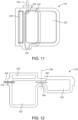
- FIGS. 11-13 show a balloon assembly 216 according to another embodiment of the present invention, and FIG. 13 shows the balloon assembly 216 attached to a hemostasis device 210 having a band 212 that is attached around the arm 2 of a patient in the vicinity of the patient's wrist.
- FIGS. 11-13 show a "side fold" design of the balloon assembly 216 which has a single, outer laser-welded perimeter that forms a channel 234 that connects a small balloon 220 and a large balloon 222 together in fluid flow communication.
- a connection tubing 244 enters the balloon assembly 216 via an inlet 218 that allows for introduction of air into the balloon assembly 216.
- the folded balloon assembly 216 of the present embodiment creates a dual-balloon structure comprising the small balloon 220, the large balloon 222, and the integrated channel 234, thereby achieving elimination of the welded connection port of the prior art devices.
- the balloon assembly 216 is completed by folding it about the fold line 236 to create a folded portion 238, and such that a first portion of the channel 234 is placed atop a second portion of the channel.
- the balloon assembly 216 is attached to the hemostasis device 210 via a single attachment hinge 240, but in alternative embodiments a side fold balloon assembly design could have two separate attachment hinges by which the balloon assembly is attached to a hemostasis device. As shown in FIG.
- a "breather" strip 235, layer, or other component can optionally be included within the channel 234 to help prevent material adhesion between the two layers of the balloon assembly 216 or kinking of the channel 234, thus reducing the likelihood that the channel 234 will fail to inflate, causing the balloon assembly 216 to fail.
- the balloon assembly when the balloon assembly is attached to the band of the hemostasis device in its intended configuration, there is some possibility that the folded channel could become tightly creased such that airflow is all or partially kinked off between the balloons.
- one or more pieces of secondary material can optionally be included within each channel to help hold the channel open.
- These "breather strips" may be one or more additional pieces of material included within the channel, which may be comprised of either air-permeable or air-impermeable materials.
- the channel(s) can be partially held open along their edge(s) by creating height along the one or more perimeter(s) of the balloon assembly construction using: one or more additional layer(s) of material; a glue line; and/or an extruded bead or weld line resulting from a RF welding process, along the one or more perimeter(s).
- FIGS. 14-16 show a balloon assembly 316 according to another embodiment of the present invention
- FIG. 16 shows the balloon assembly 316 attached to a hemostasis device 310 having a band 312 that is attached around the arm 2 of a patient in the vicinity of the patient's wrist.
- FIGS. 14 and 15 show a "center vent" folded design that is a form of end fold design in which an air channel 334 is created in the center of a side edge of the balloon assembly 316.
- the balloon assembly 316 has single, outer laser-welded perimeter that forms the single air channel 334 connecting a small balloon 320 and large balloon 322 together in fluid flow communication.
- the remainder of the side edge that includes the air channel 334 is sealed and serves as an attachment hinge 340 for connecting the balloon assembly 316 to the hemostasis device 310.
- a connection tubing 344 enters the balloon assembly 316 via an inlet 318 that allows for introduction of air into the balloon assembly 316.
- the folded balloon assembly 316 of the present embodiment creates a dual-balloon structure comprising the small balloon 320, the large balloon 322, and the integrated channel 334, thereby achieving elimination of the welded connection port of the prior art devices. As shown in FIG.
- the balloon assembly 316 is completed by folding it about the fold line 336 to create a folded portion 338, and such that a first portion of the channel 334 is placed atop a second portion of the channel 334.
- the balloon assembly 316 is attached to the hemostasis device 310 via a single attachment hinge 340 that is located along the same edge of the balloon assembly 316 as the channel 334.
- a "center-vent" end-fold balloon assembly design could have one or two separate attachment hinges located on the edge of the balloon assembly 316 opposing the edge where the channel 334 is located (i.e., on the edges of the small balloon 320 and/or large balloon 322 shown on the right side in the view of FIG. 14 ).
- a breather strip 335 may be optionally included within the channel 334.
- FIG. 17 shows another embodiment of a balloon assembly 410 according to the present invention.
- the balloon assembly 410 is formed of two separate balloons, a small balloon 424 and a large balloon 418, that are not directly connected together in fluid flow communication via an integral channel.
- a Y-shaped connector 412 that has a single air inlet and two air outlets is used, with a first connection tubing 414 routed between one of the air outlets (not labeled) of the Y-shaped connector 412 and an inlet 416 on the large balloon 418 and a second connection tubing 420 routed between the other of the air outlets (not labeled) of the Y-shaped connector 412 and an inlet 422 of the small balloon 424.
- the balloon assembly 410 is attachable to a hemostasis device via a single attachment hinge 426, but in alternative embodiments a multi-balloon assembly design with separated air input lines could have separate attachment hinges by which the balloon assembly is attached to a hemostasis device.
- FIGS. 18 and 19 show, respectively, schematic views of a side-fold balloon assembly 516 and a "center-vent" end-fold balloon assembly 616, which include respective chimney ports 518,618 that form the air inlet for the respective balloon assembly 516,616.
- balloon assembly 516 is otherwise functionally similar to balloon assembly 216 of FIGS. 11-13 and that balloon assembly 616 is otherwise functionally similar to balloon assembly 316 of FIGS. 14-16 , with like parts in the embodiments of FIGS. 18 and 19 labeled with reference numerals increased by a value of 300 with respect to the respective related embodiment.
- the channel(s) or air passages between the balloons could be of any number, could be of any non-linear shape (e.g., angled, zig-zagged, curved), and/or could split, combine, or both.
- any connection tubing could be replaced by a "chimney port" or hose barb.
- FIG. 20 a sectional view of a balloon assembly 710 according to the prior art is shown in an uninflated state, with a top layer 712 and a bottom layer 714 thereof shown adjacent to another with no air gap or space between the layers 712,714.
- this expansion failure is addressed by including spacer(s), strip(s), and/or additional layer(s) of material between the top and bottom layers of the balloon, or otherwise forming space(s) between the layers of material.
- Materials can be added within formed air channel(s) to prevent these air paths from sealing off when the balloon assembly is folded.
- These "breather strips” are formed from air-permeable materials, including but not limited to felt, thread, paper, and porous plastic.
- non-permeable materials can be placed such that they prop open air channel(s), thus allowing air to pass through the channel(s) adjacent to the material.
- Suitable non-permeable materials include but are not limited to tubing, stickers (adhesive backed paper), flexible sheets of either similar or dissimilar material to the material of the flexible sheet of the balloon, and/or cured glue. Holding channel(s) open at their edges via non-permeable materials, as shown in the example of FIG. 21 below, achieves the same effect as inserting air-permeable "breather strips" between layers of the balloon to form air channel(s). These space(s) may be located in the vicinity of the air injection port such that when air is injected into the balloon(s) the space serves as a trigger that helps peel apart any adhesions between the layers as air continues to flow into the balloon(s). Breather strips may be of any suitable cross-sectional shape, including but not limited to circular, oval, or rectangular.
- FIG. 21 shows a sectional view of a balloon assembly 810 according to the present invention in an uninflated state, with a top layer 812 and a bottom layer 814 thereof shown mostly adjacent to another, but further including spacers 816,820 along the side edges (perimeter) of the balloon assembly 810 that introduce respective air gaps 818,822 adjacent to the spacers 816,820, such that when air is introduced into the balloon assembly 810 between the top layer 812 and bottom layer 814, the air gaps 818,822 created by the spacers 816,820 serve as air flow paths that promote proper inflation of the balloon assembly 810, overcoming any adherence between the two layers 812,814. It should be understood that the assembly shown in FIG.
- 21 could be representative of the entire cross-section of a balloon assembly, or instead of one channel of a multi-channel balloon assembly. It should further be understood that a spacer or third layer of material could be included around one edge (e.g., outer perimeter) of the assembly or channel, while another edge (e.g., inner perimeter) is comprised of only two material layers.
- FIGS. 22 and 23 schematically depict a balloon assembly 910 that includes one (or more) intermediate layer(s) used as spacer(s) between top and bottom layers thereof.
- FIG. 22 schematically depicts an unfolded balloon assembly 910 formed by bonding or laser welding a top layer 922, middle layer 924, and bottom layer 926 together via a weld line 912 located around an exterior perimeter of the balloon assembly 910, and a weld line 914 located around an interior perimeter of the balloon assembly 910, with the top layer 922 and bottom layer 926 welded (or bonded) together via the exterior weld line 912 at the perimeter (leaving space 918 for an air inlet), and the middle layer 924 welded (or bonded) to both of the top layer 922 and the bottom layer 926 via weld line 914 to act as a spacer therebetween (the squares projecting upwardly and downwardly from the middle layer 924 in FIG.
- the weld line 914 creates a pair of channels 916a,916b on either side thereof, such that when the balloon assembly 910 is folded about fold line 920 to form a completed balloon, air can travel through these channels 916a,916b between the two formed balloon chambers.
- the balloon assembly 910 of the present embodiment has both two- and three-layer portions, with the three-layer portions acting to prevent expansion failure in the remainder of the balloon assembly 910. In this embodiment, once folded it is possible to cut out the interior area of the center welded area (the area inside weld line 914), since this is not necessary for proper functioning of the balloon assembly 910. By this method, an "end-fold" balloon assembly-similar to the balloon assembly 116 of FIGS. 4-10 -is constructed.
Landscapes
- Health & Medical Sciences (AREA)
- Life Sciences & Earth Sciences (AREA)
- Surgery (AREA)
- Engineering & Computer Science (AREA)
- Animal Behavior & Ethology (AREA)
- Vascular Medicine (AREA)
- Nuclear Medicine, Radiotherapy & Molecular Imaging (AREA)
- Veterinary Medicine (AREA)
- Public Health (AREA)
- Biomedical Technology (AREA)
- Heart & Thoracic Surgery (AREA)
- Medical Informatics (AREA)
- Molecular Biology (AREA)
- Reproductive Health (AREA)
- General Health & Medical Sciences (AREA)
- Biophysics (AREA)
- Hematology (AREA)
- Surgical Instruments (AREA)
Claims (15)
- Ballonanordnung (16, 116, 216, 316, 410, 516, 616, 710, 810, 910) für eine hämostatische Vorrichtung (10, 110, 210, 310), wobei die Ballonanordnung (16, 116, 216, 316, 410, 516, 616, 710, 810, 910) umfasst:eine erste Kammer (120);eine zweite Kammer (122); undmindestens einen Kanal (134a-b, 234, 334, 916a-b), der in Fluidströmungsverbindung zwischen der ersten Kammer und der zweiten Kammer steht, wobei ein einzelner Umfang der Anbringung zwischen einer ersten Materialschicht und einer zweiten Materialschicht mindestens einen Abschnitt von einem Umfang der ersten Kammer, mindestens einen Abschnitt von einem Umfang der zweiten Kammer und mindestens einen Abschnitt von einem Umfang des mindestens einen Kanals (134a-b, 234, 334, 916a-b) definiert,dadurch gekennzeichnet, dass mindestens ein Abschnitt von der ersten Kammer mindestens einen Abschnitt der zweiten Kammer überlagert, und dadurch, dass der mindestens eine Kanal gefaltet ist.
- Ballonanordnung (16, 116, 216, 316, 410, 516, 616, 710, 810, 910) nach Anspruch 1, wobei der einzelne Umfang der Anbringung die Gesamtheit der Umfänge von der ersten Kammer und der zweiten Kammer definiert.
- Ballonanordnung (16, 116, 216, 316, 410, 516, 616, 710, 810, 910) nach Anspruch 2, wobei der einzelne Umfang der Anbringung die Gesamtheit von dem Umfang des mindestens einen Kanals (134a-b, 234, 334, 916a-b) definiert.
- Ballonanordnung (16, 116, 216, 316, 410, 516, 616, 710, 810, 910) nach einem der Ansprüche 1 bis 3, wobei die Ballonanordnung (16, 116, 216, 316, 410, 516, 616, 710, 810, 910) ferner eine äußere Kante umfasst, wobei der mindestens eine Kanal (134a-b, 234, 334, 916a-b) um die äußere Kante herum gefaltet ist.
- Ballonanordnung (16, 116, 216, 316, 410, 516, 616, 710, 810, 910) nach Anspruch 4, wobei ein erster Abschnitt des mindestens einen Kanals (134a-b, 234, 334, 916a-b) einen zweiten Abschnitt des mindestens einen Kanals (134a-b, 234, 334, 916a-b) überlagert.
- Ballonanordnung (16, 116, 216, 316, 410, 516, 616, 710, 810, 910) nach Anspruch 1, die ferner mindestens ein Stück Sekundärmaterial umfasst, welches innerhalb des mindestens einen Kanals (134a-b, 234, 334, 916a-b) angeordnet ist.
- Ballonanordnung (16, 116, 216, 316, 410, 516, 616, 710, 810, 910) nach Anspruch 6, wobei das mindestens eine Stück Sekundärmaterial aus einem gasdurchlässigen Material gebildet ist.
- Ballonanordnung (16, 116, 216, 316, 410, 516, 616, 710, 810, 910) nach Anspruch 6, wobei das mindestens eine Stück Sekundärmaterial aus einem gasundurchlässigen Material gebildet ist.
- Ballonanordnung (16, 116, 216, 316, 410, 516, 616, 710, 810, 910) nach Anspruch 6, wobei das mindestens eine Stück Sekundärmaterial eine kreisförmige Querschnittsform aufweist.
- Ballonanordnung (16, 116, 216, 316, 410, 516, 616, 710, 810, 910) nach Anspruch 1, die ferner eine dritte Materialschicht umfasst, welche mindestens teilweise zwischen der ersten Materialschicht und der zweiten Materialschicht angeordnet und daran angebracht ist.
- Ballonanordnung (16, 116, 216, 316, 410, 516, 616, 710, 810, 910) nach Anspruch 1, wobei der einzelne Umfang der Anbringung einen äußeren Umfang (126) umfasst, wobei die Ballonanordnung (16, 116, 216, 316, 410, 516, 616, 710, 810, 910) ferner einen inneren Umfang (128) der Anbringung zwischen der ersten Schicht und der zweiten Schicht umfasst, wobei der innere Umfang (128) innerhalb des äußeren Umfangs (126) angeordnet ist.
- Ballonanordnung (16, 116, 216, 316, 410, 516, 616, 710, 810, 910) nach Anspruch 11, wobei der äußere Umfang (126) und der innere Umfang (128) einen ersten Luftkanal (134a-b, 234, 334, 916a-b) und einen zweiten Luftkanal (134a-b, 234, 334, 916a-b) zwischen der ersten Kammer und der zweiten Kammer bilden.
- Ballonanordnung (16, 116, 216, 316, 410, 516, 616, 710, 810, 910) nach Anspruch 12, die ferner einen ausgeschnittenen Bereich innerhalb des inneren Umfangs (128) umfasst, von dem Abschnitte von der ersten Materialschicht und der zweiten Materialschicht abwesend sind.
- Ballonanordnung (16, 116, 216, 316, 410, 516, 616, 710, 810, 910) nach Anspruch 1, die ferner einen Einlass (20, 118, 218, 318, 416, 422) umfasst, welcher entlang des Umfangs angeordnet ist, durch den ein Fluid in das Innere der Ballonanordnung (16, 116, 216, 316, 410, 516, 616, 710, 810, 910) eingeführt werden kann.
- Ballonanordnung (16, 116, 216, 316, 410, 516, 616, 710, 810, 910) nach Anspruch 14, wobei der Einlass (20, 118, 218, 318, 416, 422) die Form eines hohlen zylindrischen Rohres aufweist.
Applications Claiming Priority (2)
| Application Number | Priority Date | Filing Date | Title |
|---|---|---|---|
| US201962812436P | 2019-03-01 | 2019-03-01 | |
| PCT/US2020/020497 WO2020180730A1 (en) | 2019-03-01 | 2020-02-28 | Hemostasis devices with folded balloon assemblies |
Publications (4)
| Publication Number | Publication Date |
|---|---|
| EP3930593A1 EP3930593A1 (de) | 2022-01-05 |
| EP3930593A4 EP3930593A4 (de) | 2022-11-23 |
| EP3930593C0 EP3930593C0 (de) | 2025-06-04 |
| EP3930593B1 true EP3930593B1 (de) | 2025-06-04 |
Family
ID=81389214
Family Applications (1)
| Application Number | Title | Priority Date | Filing Date |
|---|---|---|---|
| EP20766953.2A Active EP3930593B1 (de) | 2019-03-01 | 2020-02-28 | Hämostatische vorrichtungen mit gefalteten ballonanordnungen |
Country Status (2)
| Country | Link |
|---|---|
| EP (1) | EP3930593B1 (de) |
| WO (1) | WO2020180730A1 (de) |
Families Citing this family (2)
| Publication number | Priority date | Publication date | Assignee | Title |
|---|---|---|---|---|
| JP2025071384A (ja) * | 2022-03-28 | 2025-05-07 | テルモ株式会社 | 止血デバイスおよび拡張部材の製造方法 |
| CN120753735A (zh) * | 2025-08-11 | 2025-10-10 | 北京大学人民医院 | 一种充气夹持式血管阻断器械 |
Family Cites Families (7)
| Publication number | Priority date | Publication date | Assignee | Title |
|---|---|---|---|---|
| DE60328343D1 (de) | 2002-07-15 | 2009-08-27 | Terumo Corp | Blutstillende Vorrichtung mit aufblasbarem Ballon |
| US9393027B1 (en) * | 2012-08-02 | 2016-07-19 | Frank Gleason I.P., Llc | Intravenous assist device |
| US9668744B2 (en) * | 2015-08-05 | 2017-06-06 | Vasoinnovations, Inc. | Apparatus and method to stop bleeding |
| US10390839B2 (en) * | 2014-07-11 | 2019-08-27 | Semler Technologies, Inc. | Apparatus and manufacturing means for an adjustable compression wristband |
| WO2016112342A1 (en) * | 2015-01-09 | 2016-07-14 | Hemcon Medical Technologies, Inc. | Percutaneous vascular injury treatment systems and methods |
| JP6806669B2 (ja) * | 2015-04-07 | 2021-01-06 | テルモ株式会社 | 止血器具 |
| JP7041056B2 (ja) * | 2016-07-06 | 2022-03-23 | テルモ株式会社 | 止血器具 |
-
2020
- 2020-02-28 WO PCT/US2020/020497 patent/WO2020180730A1/en not_active Ceased
- 2020-02-28 EP EP20766953.2A patent/EP3930593B1/de active Active
Also Published As
| Publication number | Publication date |
|---|---|
| EP3930593A1 (de) | 2022-01-05 |
| EP3930593A4 (de) | 2022-11-23 |
| WO2020180730A1 (en) | 2020-09-10 |
| EP3930593C0 (de) | 2025-06-04 |
Similar Documents
| Publication | Publication Date | Title |
|---|---|---|
| JP6211285B2 (ja) | 止血器具 | |
| US8419665B2 (en) | Variable length calf wrap for impulse therapy | |
| US9713476B2 (en) | Multi-layer film welded articulated balloon | |
| JP6740232B2 (ja) | 止血器具 | |
| EP2398360B1 (de) | Wärmedecke mit mehrfacheinstieg | |
| JP2002165851A (ja) | 圧縮スリーブ | |
| JP2009534111A5 (de) | ||
| WO2020180730A1 (en) | Hemostasis devices with folded balloon assemblies | |
| JP7041056B2 (ja) | 止血器具 | |
| US11590023B2 (en) | Low profile forced-air blanket | |
| US20220096097A1 (en) | Hemostasis devices with folded balloon assemblies | |
| US20220304700A1 (en) | Hemostasis band with inflatable compartments and methods of using same | |
| US20250255689A1 (en) | Surgical drape | |
| US20250255690A1 (en) | Surgical drape |
Legal Events
| Date | Code | Title | Description |
|---|---|---|---|
| STAA | Information on the status of an ep patent application or granted ep patent |
Free format text: STATUS: THE INTERNATIONAL PUBLICATION HAS BEEN MADE |
|
| PUAI | Public reference made under article 153(3) epc to a published international application that has entered the european phase |
Free format text: ORIGINAL CODE: 0009012 |
|
| STAA | Information on the status of an ep patent application or granted ep patent |
Free format text: STATUS: REQUEST FOR EXAMINATION WAS MADE |
|
| 17P | Request for examination filed |
Effective date: 20210910 |
|
| AK | Designated contracting states |
Kind code of ref document: A1 Designated state(s): AL AT BE BG CH CY CZ DE DK EE ES FI FR GB GR HR HU IE IS IT LI LT LU LV MC MK MT NL NO PL PT RO RS SE SI SK SM TR |
|
| DAV | Request for validation of the european patent (deleted) | ||
| DAX | Request for extension of the european patent (deleted) | ||
| A4 | Supplementary search report drawn up and despatched |
Effective date: 20221020 |
|
| RIC1 | Information provided on ipc code assigned before grant |
Ipc: A61M 39/10 20060101ALI20221014BHEP Ipc: A61B 17/132 20060101ALI20221014BHEP Ipc: A61B 17/00 20060101ALI20221014BHEP Ipc: A61M 39/06 20060101ALI20221014BHEP Ipc: A61M 39/02 20060101ALI20221014BHEP Ipc: A61B 17/12 20060101ALI20221014BHEP Ipc: A61B 17/135 20060101AFI20221014BHEP |
|
| GRAP | Despatch of communication of intention to grant a patent |
Free format text: ORIGINAL CODE: EPIDOSNIGR1 |
|
| STAA | Information on the status of an ep patent application or granted ep patent |
Free format text: STATUS: GRANT OF PATENT IS INTENDED |
|
| RIC1 | Information provided on ipc code assigned before grant |
Ipc: A61M 39/10 20060101ALI20241203BHEP Ipc: A61B 17/132 20060101ALI20241203BHEP Ipc: A61B 17/00 20060101ALI20241203BHEP Ipc: A61M 39/06 20060101ALI20241203BHEP Ipc: A61M 39/02 20060101ALI20241203BHEP Ipc: A61B 17/12 20060101ALI20241203BHEP Ipc: A61B 17/135 20060101AFI20241203BHEP |
|
| INTG | Intention to grant announced |
Effective date: 20250102 |
|
| GRAS | Grant fee paid |
Free format text: ORIGINAL CODE: EPIDOSNIGR3 |
|
| GRAA | (expected) grant |
Free format text: ORIGINAL CODE: 0009210 |
|
| STAA | Information on the status of an ep patent application or granted ep patent |
Free format text: STATUS: THE PATENT HAS BEEN GRANTED |
|
| AK | Designated contracting states |
Kind code of ref document: B1 Designated state(s): AL AT BE BG CH CY CZ DE DK EE ES FI FR GB GR HR HU IE IS IT LI LT LU LV MC MK MT NL NO PL PT RO RS SE SI SK SM TR |
|
| REG | Reference to a national code |
Ref country code: GB Ref legal event code: FG4D |
|
| REG | Reference to a national code |
Ref country code: CH Ref legal event code: EP |
|
| REG | Reference to a national code |
Ref country code: DE Ref legal event code: R096 Ref document number: 602020052315 Country of ref document: DE |
|
| REG | Reference to a national code |
Ref country code: IE Ref legal event code: FG4D |
|
| U01 | Request for unitary effect filed |
Effective date: 20250627 |
|
| U07 | Unitary effect registered |
Designated state(s): AT BE BG DE DK EE FI FR IT LT LU LV MT NL PT RO SE SI Effective date: 20250703 |
|
| REG | Reference to a national code |
Ref country code: ES Ref legal event code: FG2A Ref document number: 3035341 Country of ref document: ES Kind code of ref document: T3 Effective date: 20250901 |
|
| PG25 | Lapsed in a contracting state [announced via postgrant information from national office to epo] |
Ref country code: GR Free format text: LAPSE BECAUSE OF FAILURE TO SUBMIT A TRANSLATION OF THE DESCRIPTION OR TO PAY THE FEE WITHIN THE PRESCRIBED TIME-LIMIT Effective date: 20250905 Ref country code: NO Free format text: LAPSE BECAUSE OF FAILURE TO SUBMIT A TRANSLATION OF THE DESCRIPTION OR TO PAY THE FEE WITHIN THE PRESCRIBED TIME-LIMIT Effective date: 20250904 |
|
| PG25 | Lapsed in a contracting state [announced via postgrant information from national office to epo] |
Ref country code: PL Free format text: LAPSE BECAUSE OF FAILURE TO SUBMIT A TRANSLATION OF THE DESCRIPTION OR TO PAY THE FEE WITHIN THE PRESCRIBED TIME-LIMIT Effective date: 20250604 |
|
| PG25 | Lapsed in a contracting state [announced via postgrant information from national office to epo] |
Ref country code: HR Free format text: LAPSE BECAUSE OF FAILURE TO SUBMIT A TRANSLATION OF THE DESCRIPTION OR TO PAY THE FEE WITHIN THE PRESCRIBED TIME-LIMIT Effective date: 20250604 |
|
| PG25 | Lapsed in a contracting state [announced via postgrant information from national office to epo] |
Ref country code: RS Free format text: LAPSE BECAUSE OF FAILURE TO SUBMIT A TRANSLATION OF THE DESCRIPTION OR TO PAY THE FEE WITHIN THE PRESCRIBED TIME-LIMIT Effective date: 20250904 |
|
| PG25 | Lapsed in a contracting state [announced via postgrant information from national office to epo] |
Ref country code: IS Free format text: LAPSE BECAUSE OF FAILURE TO SUBMIT A TRANSLATION OF THE DESCRIPTION OR TO PAY THE FEE WITHIN THE PRESCRIBED TIME-LIMIT Effective date: 20251004 |
|
| PG25 | Lapsed in a contracting state [announced via postgrant information from national office to epo] |
Ref country code: SM Free format text: LAPSE BECAUSE OF FAILURE TO SUBMIT A TRANSLATION OF THE DESCRIPTION OR TO PAY THE FEE WITHIN THE PRESCRIBED TIME-LIMIT Effective date: 20250604 |
|
| PG25 | Lapsed in a contracting state [announced via postgrant information from national office to epo] |
Ref country code: CZ Free format text: LAPSE BECAUSE OF FAILURE TO SUBMIT A TRANSLATION OF THE DESCRIPTION OR TO PAY THE FEE WITHIN THE PRESCRIBED TIME-LIMIT Effective date: 20250604 |
|
| PG25 | Lapsed in a contracting state [announced via postgrant information from national office to epo] |
Ref country code: SK Free format text: LAPSE BECAUSE OF FAILURE TO SUBMIT A TRANSLATION OF THE DESCRIPTION OR TO PAY THE FEE WITHIN THE PRESCRIBED TIME-LIMIT Effective date: 20250604 |
|
| U20 | Renewal fee for the european patent with unitary effect paid |
Year of fee payment: 7 Effective date: 20260106 |
|
| PGFP | Annual fee paid to national office [announced via postgrant information from national office to epo] |
Ref country code: GB Payment date: 20260106 Year of fee payment: 7 |
|
| PGFP | Annual fee paid to national office [announced via postgrant information from national office to epo] |
Ref country code: ES Payment date: 20260304 Year of fee payment: 7 |
|
| PLBE | No opposition filed within time limit |
Free format text: ORIGINAL CODE: 0009261 |
|
| STAA | Information on the status of an ep patent application or granted ep patent |
Free format text: STATUS: NO OPPOSITION FILED WITHIN TIME LIMIT |
|
| REG | Reference to a national code |
Ref country code: CH Ref legal event code: L10 Free format text: ST27 STATUS EVENT CODE: U-0-0-L10-L00 (AS PROVIDED BY THE NATIONAL OFFICE) Effective date: 20260416 |
|
| U1N | Appointed representative for the unitary patent procedure changed after the registration of the unitary effect |
Representative=s name: MARKS & CLERK LLP; GB |
|
| 26N | No opposition filed |
Effective date: 20260305 |