EP3930587B1 - Systeme und vorrichtungen zur befestigung von gewebe - Google Patents
Systeme und vorrichtungen zur befestigung von gewebe Download PDFInfo
- Publication number
- EP3930587B1 EP3930587B1 EP20714791.9A EP20714791A EP3930587B1 EP 3930587 B1 EP3930587 B1 EP 3930587B1 EP 20714791 A EP20714791 A EP 20714791A EP 3930587 B1 EP3930587 B1 EP 3930587B1
- Authority
- EP
- European Patent Office
- Prior art keywords
- tissue
- actuator
- cartridge
- fastening device
- longitudinal axis
- Prior art date
- Legal status (The legal status is an assumption and is not a legal conclusion. Google has not performed a legal analysis and makes no representation as to the accuracy of the status listed.)
- Active
Links
Images


Classifications
-
- A—HUMAN NECESSITIES
- A61—MEDICAL OR VETERINARY SCIENCE; HYGIENE
- A61B—DIAGNOSIS; SURGERY; IDENTIFICATION
- A61B17/00—Surgical instruments, devices or methods
- A61B17/068—Surgical staplers, e.g. containing multiple staples or clamps
- A61B17/072—Surgical staplers, e.g. containing multiple staples or clamps for applying a row of staples in a single action, e.g. the staples being applied simultaneously
- A61B17/07207—Surgical staplers, e.g. containing multiple staples or clamps for applying a row of staples in a single action, e.g. the staples being applied simultaneously the staples being applied sequentially
-
- A—HUMAN NECESSITIES
- A61—MEDICAL OR VETERINARY SCIENCE; HYGIENE
- A61B—DIAGNOSIS; SURGERY; IDENTIFICATION
- A61B1/00—Instruments for performing medical examinations of the interior of cavities or tubes of the body by visual or photographical inspection, e.g. endoscopes; Illuminating arrangements therefor
- A61B1/00064—Constructional details of the endoscope body
- A61B1/00071—Insertion part of the endoscope body
- A61B1/0008—Insertion part of the endoscope body characterised by distal tip features
- A61B1/00087—Tools
-
- A—HUMAN NECESSITIES
- A61—MEDICAL OR VETERINARY SCIENCE; HYGIENE
- A61B—DIAGNOSIS; SURGERY; IDENTIFICATION
- A61B1/00—Instruments for performing medical examinations of the interior of cavities or tubes of the body by visual or photographical inspection, e.g. endoscopes; Illuminating arrangements therefor
- A61B1/00131—Accessories for endoscopes
- A61B1/00135—Oversleeves mounted on the endoscope prior to insertion
-
- A—HUMAN NECESSITIES
- A61—MEDICAL OR VETERINARY SCIENCE; HYGIENE
- A61B—DIAGNOSIS; SURGERY; IDENTIFICATION
- A61B1/00—Instruments for performing medical examinations of the interior of cavities or tubes of the body by visual or photographical inspection, e.g. endoscopes; Illuminating arrangements therefor
- A61B1/00131—Accessories for endoscopes
- A61B1/00137—End pieces at either end of the endoscope, e.g. caps, seals or forceps plugs
-
- A—HUMAN NECESSITIES
- A61—MEDICAL OR VETERINARY SCIENCE; HYGIENE
- A61B—DIAGNOSIS; SURGERY; IDENTIFICATION
- A61B1/00—Instruments for performing medical examinations of the interior of cavities or tubes of the body by visual or photographical inspection, e.g. endoscopes; Illuminating arrangements therefor
- A61B1/00131—Accessories for endoscopes
- A61B1/0014—Fastening element for attaching accessories to the outside of an endoscope, e.g. clips, clamps or bands
-
- A—HUMAN NECESSITIES
- A61—MEDICAL OR VETERINARY SCIENCE; HYGIENE
- A61B—DIAGNOSIS; SURGERY; IDENTIFICATION
- A61B1/00—Instruments for performing medical examinations of the interior of cavities or tubes of the body by visual or photographical inspection, e.g. endoscopes; Illuminating arrangements therefor
- A61B1/012—Instruments for performing medical examinations of the interior of cavities or tubes of the body by visual or photographical inspection, e.g. endoscopes; Illuminating arrangements therefor characterised by internal passages or accessories therefor
- A61B1/018—Instruments for performing medical examinations of the interior of cavities or tubes of the body by visual or photographical inspection, e.g. endoscopes; Illuminating arrangements therefor characterised by internal passages or accessories therefor for receiving instruments
-
- A—HUMAN NECESSITIES
- A61—MEDICAL OR VETERINARY SCIENCE; HYGIENE
- A61B—DIAGNOSIS; SURGERY; IDENTIFICATION
- A61B1/00—Instruments for performing medical examinations of the interior of cavities or tubes of the body by visual or photographical inspection, e.g. endoscopes; Illuminating arrangements therefor
- A61B1/04—Instruments for performing medical examinations of the interior of cavities or tubes of the body by visual or photographical inspection, e.g. endoscopes; Illuminating arrangements therefor combined with photographic or television appliances
- A61B1/044—Instruments for performing medical examinations of the interior of cavities or tubes of the body by visual or photographical inspection, e.g. endoscopes; Illuminating arrangements therefor combined with photographic or television appliances for absorption imaging
-
- A—HUMAN NECESSITIES
- A61—MEDICAL OR VETERINARY SCIENCE; HYGIENE
- A61B—DIAGNOSIS; SURGERY; IDENTIFICATION
- A61B17/00—Surgical instruments, devices or methods
- A61B17/00234—Surgical instruments, devices or methods for minimally invasive surgery
-
- A—HUMAN NECESSITIES
- A61—MEDICAL OR VETERINARY SCIENCE; HYGIENE
- A61B—DIAGNOSIS; SURGERY; IDENTIFICATION
- A61B17/00—Surgical instruments, devices or methods
- A61B17/068—Surgical staplers, e.g. containing multiple staples or clamps
- A61B17/072—Surgical staplers, e.g. containing multiple staples or clamps for applying a row of staples in a single action, e.g. the staples being applied simultaneously
-
- A—HUMAN NECESSITIES
- A61—MEDICAL OR VETERINARY SCIENCE; HYGIENE
- A61B—DIAGNOSIS; SURGERY; IDENTIFICATION
- A61B1/00—Instruments for performing medical examinations of the interior of cavities or tubes of the body by visual or photographical inspection, e.g. endoscopes; Illuminating arrangements therefor
- A61B1/313—Instruments for performing medical examinations of the interior of cavities or tubes of the body by visual or photographical inspection, e.g. endoscopes; Illuminating arrangements therefor for introducing through surgical openings, e.g. laparoscopes
- A61B1/3132—Instruments for performing medical examinations of the interior of cavities or tubes of the body by visual or photographical inspection, e.g. endoscopes; Illuminating arrangements therefor for introducing through surgical openings, e.g. laparoscopes for laparoscopy
-
- A—HUMAN NECESSITIES
- A61—MEDICAL OR VETERINARY SCIENCE; HYGIENE
- A61B—DIAGNOSIS; SURGERY; IDENTIFICATION
- A61B17/00—Surgical instruments, devices or methods
- A61B17/00234—Surgical instruments, devices or methods for minimally invasive surgery
- A61B2017/00292—Surgical instruments, devices or methods for minimally invasive surgery mounted on or guided by flexible, e.g. catheter-like, means
- A61B2017/00296—Surgical instruments, devices or methods for minimally invasive surgery mounted on or guided by flexible, e.g. catheter-like, means mounted on an endoscope
-
- A—HUMAN NECESSITIES
- A61—MEDICAL OR VETERINARY SCIENCE; HYGIENE
- A61B—DIAGNOSIS; SURGERY; IDENTIFICATION
- A61B17/00—Surgical instruments, devices or methods
- A61B17/00234—Surgical instruments, devices or methods for minimally invasive surgery
- A61B2017/00292—Surgical instruments, devices or methods for minimally invasive surgery mounted on or guided by flexible, e.g. catheter-like, means
- A61B2017/0034—Surgical instruments, devices or methods for minimally invasive surgery mounted on or guided by flexible, e.g. catheter-like, means adapted to be inserted through a working channel of an endoscope
-
- A—HUMAN NECESSITIES
- A61—MEDICAL OR VETERINARY SCIENCE; HYGIENE
- A61B—DIAGNOSIS; SURGERY; IDENTIFICATION
- A61B17/00—Surgical instruments, devices or methods
- A61B2017/00367—Details of actuation of instruments, e.g. relations between pushing buttons, or the like, and activation of the tool, working tip, or the like
-
- A—HUMAN NECESSITIES
- A61—MEDICAL OR VETERINARY SCIENCE; HYGIENE
- A61B—DIAGNOSIS; SURGERY; IDENTIFICATION
- A61B17/00—Surgical instruments, devices or methods
- A61B17/068—Surgical staplers, e.g. containing multiple staples or clamps
- A61B17/072—Surgical staplers, e.g. containing multiple staples or clamps for applying a row of staples in a single action, e.g. the staples being applied simultaneously
- A61B2017/07214—Stapler heads
- A61B2017/07257—Stapler heads characterised by its anvil
-
- A—HUMAN NECESSITIES
- A61—MEDICAL OR VETERINARY SCIENCE; HYGIENE
- A61B—DIAGNOSIS; SURGERY; IDENTIFICATION
- A61B17/00—Surgical instruments, devices or methods
- A61B17/068—Surgical staplers, e.g. containing multiple staples or clamps
- A61B17/072—Surgical staplers, e.g. containing multiple staples or clamps for applying a row of staples in a single action, e.g. the staples being applied simultaneously
- A61B2017/07214—Stapler heads
- A61B2017/07271—Stapler heads characterised by its cartridge
-
- A—HUMAN NECESSITIES
- A61—MEDICAL OR VETERINARY SCIENCE; HYGIENE
- A61B—DIAGNOSIS; SURGERY; IDENTIFICATION
- A61B17/00—Surgical instruments, devices or methods
- A61B17/068—Surgical staplers, e.g. containing multiple staples or clamps
- A61B17/072—Surgical staplers, e.g. containing multiple staples or clamps for applying a row of staples in a single action, e.g. the staples being applied simultaneously
- A61B2017/07214—Stapler heads
- A61B2017/07278—Stapler heads characterised by its sled or its staple holder
-
- A—HUMAN NECESSITIES
- A61—MEDICAL OR VETERINARY SCIENCE; HYGIENE
- A61B—DIAGNOSIS; SURGERY; IDENTIFICATION
- A61B17/00—Surgical instruments, devices or methods
- A61B17/068—Surgical staplers, e.g. containing multiple staples or clamps
- A61B17/072—Surgical staplers, e.g. containing multiple staples or clamps for applying a row of staples in a single action, e.g. the staples being applied simultaneously
- A61B2017/07214—Stapler heads
- A61B2017/07285—Stapler heads characterised by its cutter
Definitions
- tissue fastening including visualizing, retracting, and coupling tissue. More specifically, at least certain embodiments of the present disclosure relate to systems and devices for stapling tissue, among other aspects.
- One such difficulty involves removing a lesion from tissue.
- the user may staple tissue around the outer edge of the lesion.
- it is important to cut the tissue at a region that does not include the lesion to avoid spreading the contagious tissue.
- stapler instruments that include both stapling and cutting features that address this difficulty.
- Surgical staplers include a staple cartridge to house a plurality of staples.
- An anvil defines a surface for forming the staple legs as the staples are driven from the staple cartridge.
- the stapling operation may be effected by an actuator acting upon a staple, which often involves pushing the actuator in a distal direction to drive the staples from the cartridge.
- problems arise when pushing the actuator due to curves in portions of the stapler connecting its proximal and distal ends, and a user may find it difficult to actuate the stapler when the stapler is rotated or angled from a longitudinally straight position.
- Another difficulty involves removing a lesion from tissue by stapling its outer perimeter and cutting the lesion from the tissue.
- the user may first staple tissue around the lesion.
- the user may need to clearly observe the outer edge of the lesion, however the user's field of view may be obstructed by the stapler if the distal end of the stapler is longitudinal rigid or fixed, preventing the instrument from bending and moving out of the field of view of the user.
- the optics of the endoscope often are positioned immediately adjacent the tissue, resulting in poor recognition of the endoscope location relative to the rest of the body lumen or larger tumors.
- EP-A-1 813 211 discloses an endoscopic surgical stapler.
- a tissue fastening device may include a handle assembly including at least two actuators.
- the tissue fastening device may also include a first body extending distally from the handle assembly and defining a longitudinal axis.
- the tissue fastening device may also include a fastening device coupled to a distal end of the first body.
- the fastening device may include a longitudinal body including a channel, a cartridge configured to include a plurality of fasteners, a longitudinal channel configured to receive a device for cutting tissue, an anvil rotatable relative to the cartridge, and a fastener actuator.
- the fastener actuator may be coupled to one actuator of the at least two actuators and configured to move proximally relative to the cartridge to deploy the plurality of fasteners from the cartridge.
- the tissue fastening device may include one or more of the features below.
- the tissue fastening device may include a protrusion extending from a side surface of the fastening device and defining a lumen configured to receive a tissue acquisition tool.
- the fastening device may include a device for cutting tissue.
- the fastener actuator may be coupled to an actuation wire that extends from the fastener actuator through the elongated body to the handle assembly, and the actuation wire may be coupled to a first actuator of the at least two actuators.
- the fastener actuator may be configured to move proximally relative to the cartridge and the anvil when the first actuator is actuated.
- a distal portion of the first body may include a rigid curved portion such that a longitudinal axis of the fastening device is transverse to a longitudinal axis of a proximal portion of the first body.
- the anvil may include a first recess
- the longitudinal body may include a second recess opposing the first recess
- the first and second recesses may be configured to receive a tissue acquisition tool.
- the fastener actuator and the device for cutting tissue may be coupled to an actuation wire that extends from the fastening device through the first body to a first actuator of the handle assembly, and the first actuator may be configured to move both the fastener actuator and the device for cutting tissue proximally.
- the fastening device may be rotatably coupled to the first body.
- the fastener actuator may include a ramp, and a surface of the ramp that contacts the plurality of fasteners may have an angle of 30 degrees or less relative to a longitudinal axis of the longitudinal body.
- the fastening device may be fixedly coupled to the first body, and a longitudinal axis of the fastening device may be transverse to a longitudinal axis of the first body.
- a tissue fastening device may include a handle assembly including at least two actuators.
- the tissue fastening device may also include a first body extending distally from the handle assembly and defining a longitudinal axis.
- the tissue fastening device may further include a fastening device coupled to a distal end of the first body.
- the fastening device may include a longitudinal body including a channel.
- the fastening device may also include a cartridge that includes a plurality of fasteners.
- the fastening device may further include an anvil mounted adjacent the cartridge.
- the tissue fastening device may also include a second body including a lumen.
- the first body may be positioned in, movable within, and extends from the lumen.
- the tissue fastening device may also include a coupler coupling a distal end of the second body to the fastening device.
- the fastening device may be pivotable about the coupler when the first body is moved proximally and/or distally.
- the tissue fastening device may further include one or more of the features below.
- the second body may define an opening in a side wall of the second body and through which the first body extends.
- the second body may include a recess configured to receive a portion of the first body when the longitudinal axis of the fastening device is parallel to the longitudinal axis of the second body.
- the handle assembly may include a first actuator configured to move longitudinally in proximal and distal directions and a second actuator configured to pivot relative to a body of the handle assembly.
- a system may include a tissue fastening device and a tissue acquisition tool moveably coupled to the tissue fastening device.
- the system may also include an oversheath including a distal end opening and at least two distal end portions.
- the oversheath may be positioned around the tissue fastening device and the tissue acquisition tool.
- the oversheath may be configured to move proximally and the at least two distal end portions may be configured to move radially outward, to expose the tissue fastening device and tissue acquisition tool.
- the system may further include one or more of the features below.
- a longitudinal body including a channel and a guide protrusion.
- the guide protrusion may include a lumen configured to receive the tissue acquisition tool.
- the tissue fastening device may further include a cartridge including a plurality of fasteners; and an anvil mounted adjacent the cartridge.
- the tissue acquisition tool may be positioned within the lumen of the guide protrusion.
- a proximal portion of the oversheath may be positioned around an endoscope, and the endoscope may include an image sensor and at least two working channels. The at least two distal end portions may be biased radially inward and configured to partially enclose fastening device and tissue acquisition tool.
- the present disclosure is drawn to systems and devices for coupling, cutting, and resecting tissue, among other aspects.
- the term “distal” refers to a portion farthest away from a user when introducing a device into a patient.
- proximal refers to a portion closest to the user when placing the device into the patient.
- the term “coupling tissue together” may refer, for example, to stapling, fixing, attaching, fastening, or otherwise joining two portions of tissue together.
- fastener may include staples, clips, elastic bands, suture, or any other fastener known in the art.
- the terms “comprises,” “comprising,” or any other variation thereof, are intended to cover a non-exclusive inclusion, such that a process, method, article, or apparatus that comprises a list of elements does not necessarily include only those elements, but may include other elements not expressly listed or inherent to such process, method, article, or apparatus.
- the term “exemplary” is used in the sense of "example,” rather than “ideal.”
- Embodiments of the present disclosure may be used to visualize, cut, resect, and/or couple together target tissue in an endo-luminal space, or facilitate the process thereof.
- a tissue resecting device with a tissue stapling device.
- the tissue stapling apparatus may include a resection or cutting mechanism (e.g., an integrated knife) and a stapling mechanism (stapler).
- the stapling apparatus may be delivered to target tissue through an endoscope working channel to the target tissue site.
- the overall system may include a retraction mechanism, such as a tissue clip, to pull tissue towards the tissue stapling device. All or parts of the tissue stapling device and the retraction mechanism could be metallic, plastic, or include a shape memory metal (such as nitinol), a shape memory polymer, a polymer, or any combination of materials.
- FIG. 1 shows a surgical apparatus 100 in accordance with an embodiment of this disclosure.
- Apparatus 100 is a surgical stapling apparatus configured to engage body tissue, apply a plurality of surgical fasteners thereto, and form an incision in the fastened body tissue during minimally invasive surgical procedures, such as laparoscopic or endoscopic procedures.
- Apparatus 100 may be used to apply surgical clips or other fasteners, but will be primarily discussed in the context of applying staples from a staple cartridge positioned in a portion of the device's body, such as a loading unit.
- apparatus 100 includes a distal section 101 and a proximal section 102.
- Surgical apparatus 100 also includes a handle assembly 103, an elongate body 104, and a stapler device 105.
- the elongate body 104 may extend any length suitable for endoscopic or laparoscopic procedures, and may be configured to be positioned within a working channel of an endoscope.
- the elongate body 104 may be detachable from the handle assembly 103 to facilitate insertion of the elongate body 104 into a working channel of an endoscope or a channel of another device, for example by backloading body 104 into the working channel.
- the elongate body may be flexible and/or may be rotatable about its axis.
- the elongate body 104 may include a lumen for positioning actuation wires within for actuating the stapler device 105 via the handle assembly 103 or actuating any other portion of the apparatus 100.
- the elongate body 104 may be configured to receive a plurality of actuation wires or a single actuation wire (for example, actuation wire 118).
- the elongate body 104 may be fixedly coupled to the stapler device 105, and in other examples the elongate body 104 may be removably or releasably coupled to the stapler device 105.
- the handle assembly 103 may include a handle 106 and a body 115.
- the handle 106 may include a fixed portion 107 and an actuator portion 108.
- Fixed portion 107 of handle 106 may be fixedly coupled to body 115, and fixed portion 107 may include a circular or oval portion or ring for positioning a user's fingers within, which may assist a user in holding the handle assembly 103.
- moveable portion 108 of handle 106 may be an actuator which may be pivotally coupled to body 115 and movable relative to the fixed portion 107 of handle 106.
- Movable portion 108 may include a circular or oval portion for positioning a user's fingers within, which may assist in actuating surgical apparatus 100.
- movable portion 108 of handle 106 may be coupled to a proximal portion of an actuation wire, such as actuation wire 118, via an adjustable coupler 116 and may be configured to actuate an anvil of stapler device 105 via actuation wire 118 extending between stapler device 105 and handle assembly 103.
- movable portion 108 of handle 106 may be configured to control any other mechanism of apparatus 100, such as actuation of deploying staples from stapler device 105.
- handle assembly 103 may include a moveable cover 112 pivotably coupled to housing 115 at pivot point 112a.
- cover 112 is shown in an open position, exposing the internal portions of housing 115.
- Cover 112 may be coupled to a proximal portion of housing 115 and may cover the internal components of handle assembly 103 when positioned longitudinally parallel to housing 115, such that distalmost end 112b of cover 112 faces surface 115b of housing 115.
- Cover 112 may be temporarily fixedly coupled to a position covering the internal components of housing 115 via a coupling mechanism at a distal portion of cover 112 and a distal portion of handle assembly 103, such as a snap locking mechanism, in order to hold cover 112 in place and prevent movement of cover 112 relative to housing 115.
- cover 112 When held in place, cover 112 may form a pair of slots in housing 115 (not shown).
- a user may rotate (or pivot) cover 112 at pivot point 112a in order to have access to the internal components of handle assembly 103.
- Handle assembly 103 may further include a rotatable elongate connector 114 which may connect the elongate body 104 to handle assembly 103.
- rotatable elongate connector 114 may rotate relative to housing 115 to either tighten onto elongate body 104 in order to fixedly couple elongate body 104 to handle assembly 103, or rotated to release elongate body 104 from handle assembly 103.
- one or more adjustable couplers 116, 119 may be positioned in longitudinal alignment with, or longitudinally parallel with, rotatable elongate connector 114 and may be configured to receive a portion of an actuation wire, such as actuation wire 118.
- adjustable couplers 116, 119 may be a vice which is moveable in order to clamp down onto an actuation wire and fixedly couple actuation wire to the adjustable coupler 116, 118.
- adjustable coupler 116, 119 may be moveable via a screw to adjust the coupler 116, 119 and couple or uncouple an actuation wire from coupler 116, 119.
- Adjustable coupler 119 may be coupled to longitudinal actuator 110 and moveable longitudinally via translating longitudinal actuator 110 within housing 115.
- Longitudinal actuator 110 may be partially positioned within housing 115 and may be slidable longitudinally within two slots formed when cover 112 is positioned over the internal components of handle assembly 103.
- Longitudinal actuator 110 may include a pair of opposing circular or oval portions or rings, with each circular portion defining an aperture for a user to position their fingers within.
- longitudinal actuator 110 may be coupled to an actuation wire (not shown), such as via adjustable coupler 119 or via a different coupler within housing 115, and may be configured to control staple deployment from stapler device 105.
- longitudinal actuator 110 may be configured to control any other mechanism of apparatus 100, such as actuation of an anvil of stapler device 105.
- Distal section 101 of apparatus 100 includes a stapler device 105 coupled to a distal portion of elongate body 104.
- a connector 125 of stapler device 105 may couple elongated body 104 to stapler device 105.
- connector 125 may be offset from a longitudinal axis of the body 121 of stapler device 105.
- Body 121 of stapler device 105 may include a cartridge 122 positioned within a channel of body 121.
- Cartridge 122 may be fixedly coupled to body 121 or may be removable from body 121.
- cartridge 122 may be integrally formed in body 121.
- an anvil 120 may be rotatably or pivotably coupled to body 121 at pivot axis 120a, and may extend distally towards a distal end of stapler device 105.
- anvil 120 may be rotatably biased and may be biased to an open configuration, i.e. biased away from body 121 and cartridge 122 creating a space between the distal portion of anvil 120 and the distal portion of body 121 and cartridge 122.
- Anvil 120 may be rotatable about axis 120a to contact body 121, or pinch tissue between anvil 120 and body 121, and provide a surface for which staples may be driven when ejected from cartridge 122.
- body 121 may include a channel that supports cartridge 122.
- Cartridge 122 may contain a plurality of surgical fasteners, such as staples, and the fasteners may be deployed from cartridge 122 when under the influence of a driving force exerted by an actuation sled, such as actuation sled 341 shown in FIG. 3A .
- a plurality of spaced apart longitudinal slots 123 in cartridge 122 allow staples to pass through cartridge 122 and pierce tissue.
- an actuation sled moves proximally in the longitudinal direction from a distal end of cartridge 122 and/or body 121 when actuated, contacting fasteners within cartridge 122 and pushing fasteners through longitudinal slots 123 in order to couple fasteners to tissue.
- a single fastener may extend through each slot 123.
- Each fastener may be partially within a slot 123 prior to deployment to assist with alignment of the fastener with the slot 123.
- two actuation sleds 341, 380 may be required to actuate two different longitudinal rows of fasteners in cartridge 122 (shown in FIG. 3A ).
- anvil 120 is rotated such that a distal portion of anvil 120 comes into contact with body 121 and/or cartridge 122, or pinches tissue between anvil 120 and body 121) and such groove may be configured to receive a resecting tool such as a knife or other sharp cutting tool within the elongate longitudinal slot 124.
- the cutting tool may be actuated via an additional, separate actuation wire from the actuation wire that translated the actuation sled, or may be actuated via the same actuation wire as the actuation sled to translate both the actuation sled and the cutting tool at the same time.
- a user may use apparatus 100 to couple one or more fasteners to tissue by first positioning tissue within the active region of stapler device 105, or between body 121 and anvil 120. Once tissue is positioned in the active region of stapler device 105, a user may actuate the actuator portion 108 of handle 106, which may then translate an actuation wire proximally and cause anvil 120 to close onto the tissue positioned within the stapler device's active region. While the user holds actuation portion 108 in an engaged position, thus maintaining the stapler device's clasp on the tissue, the user may pull proximally (or actuate) longitudinal actuator 110 to translate an actuation wire coupled to an actuation sled in the stapler device.
- a ramp of the actuation sled may engage a fastener in cartridge 122 and push the fastener through a longitudinal slot 123 to pierce the tissue.
- the fastener may subsequently engage anvil 120 and couple layers of tissue together.
- the longitudinal actuator 110 may actuate an actuation wire coupled to both an actuation sled and a cutting tool, and may translate both the actuation sled and the cutting tool simultaneously to both pierce and fasten tissue with one or more fasteners and cut tissue.
- a user may backload elongate body 104 through the distal end of a working channel of an endoscope, through the body of the endoscope, and out of a proximal end of the endoscope prior to coupling the elongate body 104 to the handle assembly 103.
- a user may couple handle assembly 103 to elongate body 104 by inserting the proximal end of elongate body 104 into rotatable elongate connector 114, and then rotating rotatable elongate connector 114 to fix elongate body 104 to handle assembly 103.
- a user may then couple the proximal ends of actuation wires (such as actuation wire 118) positioned within elongate body to adjustable couplers 116, 119.
- actuation wires such as actuation wire 118
- adjustable couplers 116, 119 the user may close moveable cover 112 such that distalmost end 112b of cover 112 faces surface 115b of housing 115.
- Cover 112 may be temporarily fixedly coupled to a position covering the internal components of housing 115 via a coupling mechanism at a distal portion of cover 112, and a distal portion of handle assembly 103, such as a snap locking mechanism, in order to hold cover 112 in place during use of apparatus 100.
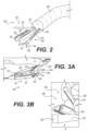
- FIG. 2 shows a distal section of an endoscope 250, a tissue acquisition tool 252 positioned within a working channel 256 of the endoscope 250, and a surgical apparatus 200 positioned within another working channel 257 of the endoscope 250, in accordance with an embodiment of this disclosure.
- Surgical apparatus 200 is substantially similar to surgical apparatus 100 and includes a stapler device 201 with longitudinal slots 223 for fastener deployment, an elongated longitudinal slot 224 for receiving a knife, and anvil 220.
- Cartridge 225 is integrally formed in body 222 of stapler device 201.
- a user may use a tissue acquisition tool 252 in combination with a stapler device, such as stapler device 201, to facilitate grabbing tissue and positioning tissue in the active portion of stapler device 201, i.e. between body 222 and anvil 220 for stapling.
- Tissue acquisition tool 252 may include an elongate body 253 extending longitudinally to a distal end portion 254.
- distal end portion 254 of tissue acquisition tool 252 may include a pair of rotatable jaws 256, 257 that are moveable between a closed configuration and an open configuration.
- a user may actuate jaws 256, 257 using an actuator present at the proximal portion of tissue acquisition tool 252 (not shown) to open and close jaws 256, 257 to facilitate grabbing and releasing tissue.
- a user may position tissue acquisition tool 252 within a working channel 256, as shown in FIG. 2 , separate from the working channel 257 in which the surgical apparatus 200 is positioned.
- a user may position tissue acquisition tool 252 in the same working channel as surgical apparatus 200 (not shown) to facilitate positioning tissue between anvil 220 and body 222.
- FIG. 3A shows a distal portion of an embodiment of surgical apparatus 300 according to the invention including stapler device 301 that is configured to receive a removable cartridge 323.
- stapler device 301 When removable cartridge 323 is removed from body 321, actuation sled 341 and knife 342 may be visible (shown in FIG. 3A ).
- actuation sled 341 and knife 342 may be visible (shown in FIG. 3A ).
- actuation sled 341 and knife 342 may be received within cartridge 323 and may not be visible.
- actuation sled 341 and knife 342 may be received within cartridge 323 and may be visible when cartridge 323 is positioned within body 321, such as by extending out of a channel in cartridge 323.
- Actuation sled 341 and knife 342 may be coupled to a single actuation wire extending to a proximal portion of surgical apparatus 300 such that, when actuated, the actuation sled 341 and knife 342 move proximally in unison.
- actuation sled 341 and knife 342 may be coupled to separate actuation wires extending from a proximal portion of either actuation sled 341 or knife 342 to a proximal portion of surgical apparatus 300, such as to handle assembly 103 such that either the actuation sled 341 or the knife 342 may be actuated independently.
- Actuation sled 341 is configured to be translated proximally to push fasteners, such as staples within cartridge 323, out of slots 345 in cartridge to fasten tissue together. Actuation sled 341 and knife 342 may be pressed by the user into a distal pocket of cartridge 323 when cartridge 323 is first positioned within body 321.
- Actuation sled 341 may include a ramp 346 that is configured to engage, directly or indirectly, staples, or other fasteners from within cartridge 323 through slots 345, to deploy fasteners to couple tissue.
- ramp 346 may be angled at 45 degrees, 40 degrees, 35 degrees, 30 degrees, 25 degrees, or any other angle relative to a longitudinal axis of body 321.
- Ramp 341 may be a shallow angle to require the actuation sled 341 to translate proximally for a longer distance in order to deploy fasteners in cartridge 323.
- actuation sled 341 By providing actuation sled 341 with a shallow angle, long ramp 341, a user may engage multiple fasteners at the same time when pulling actuation sled 341 proximally, and thus allowing, in some examples, multiple staples to deploy and pierce tissue at the same time.
- a shallow angle ramp 346 e.g. an angle approximately 30 degrees or less, may prevent intermittent forces being applied to the actuator in the handle assembly due to the actuation sled 341 releasing from a fastener before engaging the next fastener, by continuously engaging fasteners in cartridge 323, and thus may prevent errors during a procedure by providing a more continuous force applied to the actuator.
- the ramp 346 of actuation sled 341 may engage two, three, four, or more fasteners in cartridge 323 at the same time. Since actuation sled 341 is pulled proximally to deploy fasteners, a user may generate higher loads when pulling a flexible wire, such as an actuation wire 118 shown in FIG. 1 , compared to a pushing mechanism to deploy fasteners.
- An actuation body 343 may extend proximally from a proximal portion of ramp 346, and actuation sled 341 may be pulled from the actuation body 343 to deploy fasteners.
- actuation body 343 may be coupled to an actuation wire that extends to a proximal portion of the surgical apparatus 300.
- apparatus 300 may include two actuation sleds 341 and two actuation bodies 343 coupled to the same actuation wire to engage and deploy two separate rows of fasteners in cartridge 323.
- Knife 342 may have a similar structure to actuation sled 341 and may include a hooked distal portion 344 that includes sharp edges for cutting tissue. Knife 342 may be configured to travel longitudinally within an elongated longitudinal slot of cartridge 323. In some examples, a portion of knife 342 extends into a groove of anvil 320, such as groove 370 shown in FIG. 3B , and travels within the groove longitudinally from the distal end of anvil 320 to the proximal end when a user actuates knife 342, thus translating knife 342 longitudinally across cartridge 323 to cut tissue.
- FIG. 3B shows a distal portion of an alternative embodiment of surgical apparatus 355 including stapler device 356 that is configured to receive a removable cartridge 363.
- body 361 includes a distal end with a distal front face 362 that encloses cartridge 363 within body 361 with only the top portion of cartridge 363, or the portion of cartridge 363 opposing a bottom surface of anvil 360, exposed.
- Distal front face 362 prevents the distal end of cartridge 363, or in some examples an actuation sled and/or a knife, from contacting tissue when moving stapler device 356.
- Anvil 360 includes a groove 370 within a surface opposing cartridge 363, configured to receive a knife when anvil 360 is in a closed position.
- FIG. 4A shows an enlarged, cross-sectional view of an exemplary stapler device 401 including body 421, anvil 420, cartridge 423 with fasteners 445, and actuation sled 441 with actuation body 443.
- the stapler device 401 in FIG. 4A is shown deploying fasteners 445 onto tissue 449.
- Actuation sled 441 engages pistons or spacers 451, and the pistons or spacers 451 then engage the fasters 445 to deploy the fasteners 445.
- actuation sled 441 engages the pistons or spacers 451 as actuation sled 441 moves in the proximal direction P.
- Each piston or spacer 451 may be configured to translate within cartridge 423 and may be sized to engage only one fastener. In other examples, each piston or spacer 451 may be sized to engage multiple fasteners, or one or more pistons or spacers 451 may be sized to engage multiple fasteners while one or more other pistons or spacers 451 may be sized to engage only one fastener.
- Actuation sled 441 may be configured to move each piston or spacer 451 in a direction transverse to the longitudinal axis of body 421. For example, actuation sled 441 and actuation body 443 may be pulled proximally via an actuation wire, which may move ramp 442 (shown in FIG.
- each of the pistons or spacers 451 may have an upper surface that aligns and/or is flush with a portion of each respective fastener 445.
- each fastener 445 may be a staple and may include three substantially flat sections with the middle substantially flat section aligning with the top surface of each spacer 451.
- Each piston or spacer 451 may be sufficiently rigid to move uniformly upward when the ramp 442 of actuation sled engages a corner of the piston or spacer 451.
- each piston or spacer 451 may be coupled to cartridge 423 such that movement along the longitudinal axis of cartridge 423, or in the proximal P or distal D directions shown in FIG. 4A , is prevented while allowing movement in a direction perpendicular to the longitudinal axis of cartridge 423.
- the pistons or spacers 451 in cartridge 423 may prevent fasteners 445, such as staples, from partially deploying and may avoid improper stapling caused by a distal portion of a staple moving upward when a proximal portion of the staple does not move.
- the ramp 442 of actuation sled 441 can move proximally and push each fastener 445 uniformly upward by engaging each spacer.
- FIG. 4B shows an exemplary actuation sled 441 including a ramp 442, a width 475, a height 477, and an actuation body 443.
- Ramp 442 may include a first proximal section 444 and a second distal section 446.
- the first proximal section 444 may have a different incline angle 473 than the incline angle 471 of the second distal section 446.
- the first proximal section 446 may have an incline angle of 30 degrees and the second distal section may have an incline angle of 20 degrees.
- actuation sled 441 may push spacers 451 with varying levels of pressure as it moves proximally.
- first proximal section 446 and the second distal section 446 may have the same incline angles 471, 473 or they may have any other angle between 0 and 90 degrees.
- actuation sled 441 may have a length 475 of .50 inches (12,7 mm) and a height of .215 inches (5,5 mm).
- Actuation body 443 may extend from the bottom of ramp 442 and, in some examples, may also extend the length 475 of the actuation sled 441.
- actuation body may be .008 inch (0,2 mm) diameter stainless steel wire.
- FIG. 4B shows a partial cross-sectional view of an exemplary actuation sled 441, a portion of an anvil 420 including a recess 450 in the anvil's surface that faces cartridge 423, a portion of a cartridge 423, a fastener 445, and tissue 449 positioned between cartridge 423 and anvil 420.
- actuation sled 441 When actuation sled 441 is actuated, for exampled pulled from its proximal end 443 proximally via an actuation mechanism such as an actuator in handle assembly 103, ramp 442 will engage fastener 445 and translate fastener towards tissue 449 to pierce tissue 449 as the actuation sled 441 moves in the proximal direction.
- a pin may be positioned between fastener 445 and actuation sled 441, and ramp 442 may engage the pin instead of fastener 445, the pin forcing the fastener 445 towards tissue 449.
- ramp 442 may engage the pin instead of fastener 445, the pin forcing the fastener 445 towards tissue 449.
- FIG. 5A shows an exemplary stapler device 501 that is angled relative to the longitudinal axis 560 of endoscope 550 and radially displaced from the endoscope's longitudinal axis 560.
- Elongate body 555 may include a distal end exposed from the endoscope, the distal end may be biased into a curved orientation (shown in FIG. 5A ) such that the longitudinal axis 561 of the stapler device 501 intersects the longitudinal axis 560 of the endoscope 550 in which a portion of elongate body 555 is positioned within.
- the angle formed between the longitudinal axis 561 of stapler device 501 and the longitudinal axis 560 of the endoscope 550 may be fifteen degrees, thirty degrees, forty-five degrees, sixty degrees, or any other angle.
- the distal end of body 555 may include links or other structure that causes the distal end to be in a rigid or substantially rigid configuration shown in FIG. 5A.
- FIG. 5B shows an alternative view of stapler device 501 in which elongate body 555 has been rotated ninety degrees to position stapler device 501 such that the longitudinal axis 561 of stapler device 501 is angled away from the longitudinal axis 560 of endoscope 550.
- Axis 562 shows an axis perpendicular to longitudinal axis 560.
- elongate body 555 that is rigidly curved or otherwise biased curved to angle the longitudinal axis 561 of stapler device 501 relative to the longitudinal axis 560 of endoscope 550
- the user's working space may be modified to allow for greater visualization, for example visualization through a camera positioned at the distal end of endoscope 550.
- Other benefits of angling stapler device 501 relative to the longitudinal axis of endoscope 550 may include facilitating alignment with a tissue acquisition tool and aiding in positioning tissue between the anvil and the body of stapler device 501.
- elongated body 555 may be articulable to angle and radially offset stapler device 501. Body may be articulated via articulation links activated at a proximal end of endoscope 550.
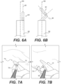
- FIGs. 6A and 6B show an example of a center line 660 of a field of view of a camera at the distal end of endoscope 650.
- the longitudinal axis 661 of stapler device 601 is parallel to the center line 660, and thus stapler device 601 is positioned on a side of the field of view.
- FIG. 6B shows stapler device 601 angled relative to the center line 660 of a field of view of a camera.
- the longitudinal axis 661 intersects with the center line 660 and positions the distal end portion of stapler device 601 directly within the center of the field of view of the camera of endoscope 650.
- FIGs. 7A and 7B show a field of view of a camera at a distal end of an endoscope in which a stapler device 701 and a tissue acquisition tool 754 are being utilized to manipulate and couple tissue 770. Since stapler device 701 is angled relative to the longitudinal axis of the endoscope, the field of view includes a view of the space between the anvil and the body of stapler device 701, facilitating the positioning of tissue 770 between the anvil and body for stapling.
- FIG. 8 shows an example of an alternative embodiment of a stapler device 801 including a guide protrusion 840.
- Guide protrusion 840 may include a lumen 842 configured to receive a tissue acquisition tool 844.
- Tissue acquisition tool 844 may be positioned within lumen 842 of guide protrusion 840 prior to inserting endoscope 843 into a patient's body.
- Tool 844 and stapler device 801 can be backloaded into one or more lumens of endoscope 843.
- Pre-aligning a tissue acquisition tool 844 within guide protrusion's lumen 842 may facilitate positioning tissue acquisition tool 844 within the space 846 between stapler device's 801 anvil and body (i.e.
- Lumen 842 may be curved or otherwise angled towards stapler device 801 to bend tissue acquisition tool 844 towards stapler device 801.
- the plane of the distal opening of lumen 842 may be angled to face the stapler device's active region.
- Guide protrusion 840 may extend radially away from a portion of stapler device 801 that is proximal to stapler device's 801 anvil or space 846.
- Guide protrusion 840 may be fixed to stapler device 801.
- guide protrusion 840 may be rigid or may be semi-rigid.
- Guide protrusion 840 may include a lumen 842 that includes a central longitudinal axis that is spaced from the longitudinal axis of stapler device 801.
- FIG. 9 shows an exemplary embodiment of a stapler device 901 including anvil 920, body 922, recess 946 in anvil 920, and recess 947 in body 922.
- Recesses 946, 947 may be positioned on radially inward facing surfaces of anvil 920 and body 922 respectively, opposing each other and may form a lumen between anvil 920 and body 922 when anvil 920 and body 922 are in a closed position that lumen traverses the longitudinal axis of stapler device 901.
- a tissue acquisition tool 944 may be positioned within lumen recesses 946, 947 when stapler device 901 is in a closed position such that when elongated body 943 of tissue acquisition tool 944 is translated proximally, the distal end of tissue acquisition tool 944 is moved into the space between anvil 920 and body 922. Pre-positioning tissue acquisition tool 944 within the space between anvil 920 and body 922, or within the active portion of stapler device 901, may allow a user to more easily position the distal end of tissue acquisition tool 944 and tissue within the active portion of stapler device 901. Tissue acquisition tool 944 may be preloaded into the lumen formed by recesses 946, 947 prior to insertion into a patient's body.
- FIGs. 10A and 10B show front and side perspective views of an exemplary multi-lumen oversheath 1050 including shaft 1051, distal end portion 1053, lumens 1052, 1054, and 1056.
- Oversheath 1050 may provide a user with means for utilizing a tissue acquisition tool, a stapling device, and a steerable visualization tool, such as an endoscope that includes a camera.
- FIG. 11 shows a front view of oversheath 1050 with an endoscope 1140 positioned within lumen 1052. Since endoscope 1140 includes a single working channel 1142, oversheath 1050 provides the user with three total working channels, i.e. lumens 1054, 1056 and working channel 1142.
- oversheath 1250 shows another exemplary embodiment of an oversheath 1250 including two lumens 1252, 1254 with an endoscope 1240 positioned within lumen 1252. Since endoscope 1240 includes a working channel 1242, the oversheath 1250 provides an additional working channel (i.e. lumen 1254) for the user to utilize.
- Each of oversheath 1050 and 1250 may extend along the entire length of the endoscope 1140, 1240. In other examples, oversheath 1050, 1250 may extend along only a portion of endoscope 1140, 1240.
- FIGs. 13 and 14 show alternative embodiments of oversheaths 1350, 1450 with lumens 1352, 1354, 1356, 1452, 1456.
- Oversheaths 1350, 1450 extend along only a portion of the distal end of an endoscope that they are positioned over, such as distal ends of endoscope 1340 or endoscope 1440 shown in FIGs. 13 and 14 .
- Positioning either a stapler device or a tissue acquisition tool within a lumen of an oversheath may move the device or tool farther radially away from the center of the field of view of a camera at the distal end of an endoscope, and may provide a less obstructed view of target tissue the user seeks to position in the active region of the stapler.
- an oversheath may be used to protect the patient's tissue from unwanted contact with devices at the distal end of an endoscope while the endoscope travels through the patient's body.
- FIG. 15 shows an exemplary oversheath 1552 positioned over an endoscope 1540. Extending distally from the distal end of endoscope 1540 are stapler device 1501 and tissue acquisition tool 1543, much like the devices shown in FIG. 8 , though any tools may be used with oversheath 1552.
- Oversheath 1552 is positioned over stapler device 1501 and tissue acquisition tool 1543, and may prevent stapler device 1501 and tissue acquisition tool 1543 from contacting tissue and/or moving radially outward from the longitudinal axis of endoscope 1540, as endoscope 1540 moves through a patient's body.
- An opening 1570 at the distal end of oversheath 1552 may provide the user with the ability to view in front of the endoscope 1540 while the endoscope 1540 and oversheath 1552 move through a patient's body. Opening 1570 may include one or more proximally extending slots 1570a (4 shown in FIG. 16 ).
- Distal portions 1555, 1556 of oversheath 1552 may be movable and flexible to expand and contract opening 1570.
- An exemplary expanded state of opening 1570 is shown as opening 1571 with dotted lines 1557, 1558 representing distal portions 1555, 1556 after having moved radially outward.
- Distal portions 1555, 1556 may move radially outwardly to form an expanded state in order to allow a user to access a target area with stapler device 1501 and tissue acquisition tool 1543.
- oversheath 1552 may include longitudinal slits 1567 that can be torn.
- a tearable slit 1567 may extend from each of slots 1570a proximally a distance sufficient to allow separation of portions 1555, 1556 (e.g. to the distal face of endoscope 1540).
- distal portions 1555, 1556 may be movable to allow the user to pull oversheath 1550 proximally and position stapler device 1501 and tissue acquisition tool 1543 within a target area.
- oversheath 1550 may include four distal portions 1555, 1556, 1565, 1566 that may be moveable.
- each of distal portions 1555, 1556, 1565, 1566 of oversheath 1550 may be configured to move proximally or distally relative to endoscope 1540 to allow a user to uncover or cover stapler device 1501 and tissue acquisition tool 1543.
- distal portions 1555, 1556, 1565, 1566 may move radially outward to expand opening 1570 in order to allow acquisition tool 1543 and stapler device 1501 to pass through opening 1570.
- distal portions 1555, 1556, 1565, 1566 may move radially outward when contacted by the stapler device 1501 and/or acquisition tool 1543 as the oversheath 1552 is translated proximally.
- oversheath 1550 may be transparent/clear to allow a user to see through oversheath 1550 as endoscope 1540 moves through a patient's body.
- FIG. 17 shows an exemplary medical apparatus 1700 including a stapler device 1701, an elongate body 1704, an elongate rod 1770 including a lumen 1772, and a rotatable connector 1780.
- the stapler device 1701 and elongate body 1704 may include any of the features and characteristics discussed hereinabove.
- Rod 1770 may be rigid and may be manufactured from polyether ether ketone (PEEK) or other suitable materials.
- Elongate body 1704 may be a non-compressible member, such as a Bowden cable, and may include a lumen (not shown) for receiving actuation wires and other components of stapler device 1701.
- Lumen 1772 of rod 1770 may extend longitudinally from a proximal end to a distal portion of rod 1770.
- lumen 1772 may receive elongate body 1704 and may be configured to allow elongated body to move proximally and distally through lumen 1772.
- Body 1704 may extend out of lumen 1772 via an opening 1779 in a side wall of rod 1770.
- Rotatable connector 1780 may couple stapler device 1701 to rod 1770 and may be positioned between the proximal and distal ends of stapler device 1701.
- rotatable connector 1780 permits pivoting of stapler device 1701 relative to rod 1770 such that stapler device 1701 may move between a position where the longitudinal axis of stapler device 1701 is parallel with the longitudinal axis of rod 1770 and a position where the longitudinal axis of stapler device 1701 is transverse to the longitudinal axis of rod 1770.
- rotatable connector 1780 may permit such pivoting so that the angle between the longitudinal axes is greater than zero degrees and up to as much as 180 degrees, where the longitudinal axis of stapler device 1701 is parallel with the longitudinal axis of rod 1770.
- FIGs. 18-21 show various views of medical apparatus 1700 with stapler device 1701 rotated various degrees relative to rod 1770. As shown in FIGs.
- lumen opening 1779 may be oval shaped and may be elongate in the longitudinal direction of rod 1770 to allow elongate body 1704 to smoothly transition into and out of rod 1770 and to minimize friction between lumen opening 1779 and elongate body 1704 when elongate body 1704 moves through lumen opening 1779.
- a user may pivot stapler device 1701 by pushing or pulling on elongate body 1704 (to move elongated body 1704 proximally or distally), which then pushes or pulls on stapler device 1701 and causes stapler device 1701 to rotate about rotatable connector 1780.
- rotatable connector 1780 may include a pin extending through a device at a distal end of rod 1770 and a flange extending from stapler device 1701.
- Stapler device 1701 may include a pair of flanges extending from a portion of its body that include apertures for a pin
- rod 1770 may include a device extending from a distal end of rod 1770 including an aperture that is configured to align with the apertures of the pair of flanges
- a pin may be positioned with the apertures of the pair of flanges and the aperture of the device extending from a distal end of rod 1770 to form rotatable connector 1780.
- a user may load an elongate body of a stapler device in a working channel of an endoscope by backfeeding the elongate body through a distal end of an endoscope working channel to position a portion of the elongate body within the working channel.
- a handle assembly may be coupled to the proximal end of the elongate body. The user may then introduce the endoscope into the patient's body and move the endoscope towards a target area.
- the user may locate a target area (such as a tumor or other diseased tissue) present in a body lumen of a subject using the endoscope by directly visualizing the target area using an image sensor.
- a target area such as a tumor or other diseased tissue
- the user may position a tissue acquisition tool within a working channel of the endoscope, if such a tool is not already present.
- the user may move the oversheath proximally to expose the stapler device to the target area and/or tear away portions of the oversheath to expose the stapler device.
- the user may actuate the stapler device to an open position creating a space between the stapler's anvil and body.
- the user may then introduce the tissue acquisition tool to the target area and position the tissue acquisition tool between or close to the active portion of the stapler device, e.g. the space between the stapler device's anvil and body.
- the user may then grasp tissue with the tissue acquisition tool and move tissue into the stapler device's active portion. Once tissue is positioned within the stapler device's active portion, the user may move the stapler device's anvil and body to a closed position and clamp down on the grasped tissue with the stapler device.
- the user may then actuate an actuator in order to pull on an actuation wire, thus moving an actuation sled of the stapler device proximally.
- an actuator By moving the actuation sled proximally via an actuator, the user may deploy fasteners into the clamped tissue and against the stapler device's anvil.
- the user may actuate a knife in the stapler device to cut portions of the target tissue either before or after fastening tissue together via fasteners.
- the user may be able to increase visualization of the target tissue and may prevent unwanted stapling errors, such as stapling within portions of contagious tissue.
- the increased visualization from a maneuverable, flexible stapler also may aid in ensuring that as much of or all of a target lesion is removed.
Landscapes
- Health & Medical Sciences (AREA)
- Life Sciences & Earth Sciences (AREA)
- Surgery (AREA)
- Nuclear Medicine, Radiotherapy & Molecular Imaging (AREA)
- Molecular Biology (AREA)
- Veterinary Medicine (AREA)
- Public Health (AREA)
- General Health & Medical Sciences (AREA)
- Animal Behavior & Ethology (AREA)
- Engineering & Computer Science (AREA)
- Biomedical Technology (AREA)
- Heart & Thoracic Surgery (AREA)
- Medical Informatics (AREA)
- Physics & Mathematics (AREA)
- Biophysics (AREA)
- Radiology & Medical Imaging (AREA)
- Pathology (AREA)
- Optics & Photonics (AREA)
- Surgical Instruments (AREA)
Claims (15)
- Gewebebefestigungsvorrichtung, aufweisend:eine Griffbaugruppe (103) mit mindestens zwei Aktuatoren (108, 110);einen ersten Körper (104), der sich distal von der Griffbaugruppe erstreckt und eine Längsachse definiert;eine Befestigungsvorrichtung (300), die mit einem distalen Ende des ersten Körpers gekoppelt ist, wobei die Befestigungsvorrichtung aufweist:einen Längskörper mit einem Kanal (327);eine Patrone (323), die zum Enthalten von mehreren Befestigungselementen konfiguriert ist; wobei die Patrone einen Längskanal aufweist, der zum Aufnehmen einer Vorrichtung zum Schneiden von Gewebe (342) konfiguriert ist;einen Amboss, der relativ zu der Patrone drehbar ist; undeinen Befestigungselement-Aktuator (341), der mit einem Aktuator der mindestens zwei Aktuatoren gekoppelt ist, dadurch gekennzeichnet, dass der Befestigungselement-Aktuator so konfiguriert ist, dass er sich in proximaler Richtung relativ zu der Patrone bewegt, um die mehreren Befestigungselemente aus der Patrone zum Einsatz zu bringen.
- Vorrichtung nach Anspruch 1, wobei die Befestigungsvorrichtung einen Vorsprung (840) aufweist, der sich von einer Seitenfläche der Befestigungsvorrichtung aus erstreckt und ein Lumen (842) definiert, das zum Aufnehmen eines Gewebeerfassungswerkzeugs konfiguriert ist.
- Vorrichtung nach einem der vorstehenden Ansprüche, wobei die Befestigungsvorrichtung die Vorrichtung zum Schneiden von Gewebe aufweist.
- Vorrichtung nach einem der vorstehenden Ansprüche, wobei der Befestigungselement-Aktuator mit einem Betätigungsdraht (118) gekoppelt ist, der sich von dem Befestigungselement-Aktuator durch den länglichen Körper zu der Griffbaugruppe erstreckt, wobei der Betätigungsdraht mit dem einen Aktuator der mindestens zwei Aktuatoren gekoppelt ist, und wobei der Befestigungselement-Aktuator so konfiguriert ist, dass er sich in proximaler Richtung relativ zu der Patrone und dem Amboss bewegt, wenn der erste Aktuator betätigt wird.
- Vorrichtung nach einem der vorstehenden Ansprüche, wobei ein distaler Abschnitt des ersten Körpers einen gekrümmten Abschnitt aufweist, sodass eine Längsachse der Befestigungsvorrichtung quer zu einer Längsachse eines proximalen Abschnitts des ersten Körpers verläuft.
- Vorrichtung nach einem der vorstehenden Ansprüche, wobei der Amboss eine erste Aussparung aufweist, wobei der Längskörper eine zweite Aussparung aufweist, die der ersten Aussparung gegenüberliegt, und wobei die erste und die zweite Aussparung zum Aufnehmen eines Gewebeerfassungswerkzeugs konfiguriert sind.
- Vorrichtung nach Anspruch 3, wobei der Befestigungselement-Aktuator und die Vorrichtung zum Schneiden von Gewebe mit einem Betätigungsdraht verbunden sind, der sich von der Befestigungsvorrichtung durch den ersten Körper zu einem ersten Aktuator der Griffbaugruppe erstreckt, und wobei der erste Aktuator zum Bewegen sowohl des Befestigungselement-Aktuators als auch der Vorrichtung zum Schneiden von Gewebe in proximaler Richtung konfiguriert ist.
- Vorrichtung nach einem der vorstehenden Ansprüche, wobei die Befestigungsvorrichtung drehbar mit dem ersten Körper gekoppelt ist.
- Vorrichtung nach einem der vorstehenden Ansprüche, wobei der Befestigungselement-Aktuator eine Rampe (346) aufweist,
und wobei eine Fläche der Rampe, die einen Kolben oder einen Abstandshalter berührt, um die mehreren Befestigungselemente zum Einsatz zu bringen, einen Winkel von 30 Grad oder weniger relativ zu einer Längsachse des Längskörpers aufweist. - Vorrichtung nach einem der vorstehenden Ansprüche, wobei die Befestigungsvorrichtung fest mit dem ersten Körper verbunden ist und wobei eine Längsachse der Befestigungsvorrichtung quer zu einer Längsachse des ersten Körpers verläuft.
- Vorrichtung nach einem der vorstehenden Ansprüche, ferner aufweisend: einen zweiten Körper (1770) mit einem Lumen (1772),wobei der erste Körper in dem Lumen positioniert ist, darin beweglich ist und sich von diesem aus erstreckt, undeinen Koppler, der ein distales Ende des zweiten Körpers mit der Befestigungsvorrichtung koppelt, wobei die Befestigungsvorrichtung um den Koppler schwenkbar ist, wenn der erste Körper proximal und/oder distal bewegt wird.
- Vorrichtung nach Anspruch 11, wobei der zweite Körper eine Öffnung (1779) in einer Seitenwand des zweiten Körpers definiert, durch die sich der erste Körper erstreckt.
- Vorrichtung nach Anspruch 11 oder 12, wobei der zweite Körper eine Aussparung aufweist, die zum Aufnehmen eines Teils des ersten Körpers konfiguriert ist, wenn die Längsachse der Befestigungsvorrichtung parallel zur Längsachse des zweiten Körpers verläuft.
- Vorrichtung nach einem der vorstehenden Ansprüche, wobei einer der mindestens zwei Aktuatoren (108, 110) ein erster Aktuator ist, der so konfiguriert ist, dass er sich in Längsrichtung in proximaler und distaler Richtung bewegt, und einer der mindestens zwei Aktuatoren (108, 110) ein zweiter Aktuator ist, der zum Schwenken relativ zu einem Körper der Griffbaugruppe konfiguriert ist.
- Vorrichtung nach Anspruch 11, 12 oder 13, wobei der Koppler proximal zu den Befestigungselementen positioniert ist.
Applications Claiming Priority (2)
| Application Number | Priority Date | Filing Date | Title |
|---|---|---|---|
| US201962812538P | 2019-03-01 | 2019-03-01 | |
| PCT/US2020/020375 WO2020180678A1 (en) | 2019-03-01 | 2020-02-28 | Systems, devices, and related methods for fastening tissue |
Publications (2)
| Publication Number | Publication Date |
|---|---|
| EP3930587A1 EP3930587A1 (de) | 2022-01-05 |
| EP3930587B1 true EP3930587B1 (de) | 2025-02-26 |
Family
ID=70009425
Family Applications (1)
| Application Number | Title | Priority Date | Filing Date |
|---|---|---|---|
| EP20714791.9A Active EP3930587B1 (de) | 2019-03-01 | 2020-02-28 | Systeme und vorrichtungen zur befestigung von gewebe |
Country Status (5)
| Country | Link |
|---|---|
| US (1) | US11717292B2 (de) |
| EP (1) | EP3930587B1 (de) |
| JP (1) | JP7604385B2 (de) |
| CN (1) | CN113766885B (de) |
| WO (1) | WO2020180678A1 (de) |
Families Citing this family (11)
| Publication number | Priority date | Publication date | Assignee | Title |
|---|---|---|---|---|
| US10299773B2 (en) * | 2011-08-21 | 2019-05-28 | Transenterix Europe S.A.R.L. | Device and method for assisting laparoscopic surgery—rule based approach |
| JP2022542050A (ja) * | 2019-07-24 | 2022-09-29 | ボストン サイエンティフィック サイムド,インコーポレイテッド | 締結装置 |
| CN120837145A (zh) * | 2019-07-24 | 2025-10-28 | 波士顿科学国际有限公司 | 用于紧固组织的装置 |
| CN116782837A (zh) * | 2020-12-24 | 2023-09-19 | 奥林巴斯株式会社 | 医疗用缝合器及缝合方法 |
| EP4267017A1 (de) | 2020-12-28 | 2023-11-01 | Boston Scientific Scimed, Inc. | Steuermechanismus für endeffektoren |
| WO2022147425A1 (en) * | 2020-12-28 | 2022-07-07 | Boston Scientific Scimed, Inc. | Control mechanism for end effectors and method of use |
| JP7834769B2 (ja) * | 2021-03-03 | 2026-03-24 | ボストン サイエンティフィック サイムド,インコーポレイテッド | 組織を固定するためのシステム、装置、および関連する方法 |
| WO2023037487A1 (ja) * | 2021-09-10 | 2023-03-16 | オリンパス株式会社 | 医療用ステープラおよび縫合方法 |
| WO2023227506A1 (en) | 2022-05-23 | 2023-11-30 | Biotronik Ag | Endovascular stapling system for resection of the laa |
| WO2023248361A1 (ja) * | 2022-06-21 | 2023-12-28 | オリンパス株式会社 | 医療用ステープラ |
| CN120731047A (zh) * | 2024-01-29 | 2025-09-30 | 奥林巴斯株式会社 | 医疗用缝合器 |
Citations (1)
| Publication number | Priority date | Publication date | Assignee | Title |
|---|---|---|---|---|
| WO2021158545A1 (en) * | 2020-02-04 | 2021-08-12 | Boston Scientific Scimed, Inc. | Actuator mechanisms for end effectors |
Family Cites Families (20)
| Publication number | Priority date | Publication date | Assignee | Title |
|---|---|---|---|---|
| US3490675A (en) | 1966-10-10 | 1970-01-20 | United States Surgical Corp | Instrument for placing lateral gastrointestinal anastomoses |
| ATE150954T1 (de) * | 1991-07-29 | 1997-04-15 | Smith & Nephew Richards Inc | Zange |
| US5507426A (en) * | 1994-08-05 | 1996-04-16 | United States Surgical Corporation | Apparatus for applying surgical fasteners |
| US5782396A (en) | 1995-08-28 | 1998-07-21 | United States Surgical Corporation | Surgical stapler |
| US6109500A (en) * | 1996-10-04 | 2000-08-29 | United States Surgical Corporation | Lockout mechanism for a surgical stapler |
| US8252009B2 (en) * | 2004-03-09 | 2012-08-28 | Ethicon Endo-Surgery, Inc. | Devices and methods for placement of partitions within a hollow body organ |
| US7575144B2 (en) | 2006-01-31 | 2009-08-18 | Ethicon Endo-Surgery, Inc. | Surgical fastener and cutter with single cable actuator |
| US8062211B2 (en) * | 2006-06-13 | 2011-11-22 | Intuitive Surgical Operations, Inc. | Retrograde instrument |
| US7794475B2 (en) * | 2006-09-29 | 2010-09-14 | Ethicon Endo-Surgery, Inc. | Surgical staples having compressible or crushable members for securing tissue therein and stapling instruments for deploying the same |
| EP2044892A3 (de) * | 2007-10-05 | 2012-11-21 | Tyco Healthcare Group LP | Chirurgische Klammervorrichtung |
| US8490851B2 (en) * | 2008-01-15 | 2013-07-23 | Covidien Lp | Surgical stapling apparatus |
| EP2337488B1 (de) | 2008-07-18 | 2016-05-25 | Boston Scientific Scimed, Inc. | Geführtes endoskop |
| US8506479B2 (en) | 2009-12-16 | 2013-08-13 | Macroplata, Inc. | Substantially rigid and stable endoluminal surgical suite for treating a gastrointestinal lesion |
| US8672209B2 (en) * | 2010-02-25 | 2014-03-18 | Design Standards Corporation | Laproscopic stapler |
| US8562592B2 (en) * | 2010-05-07 | 2013-10-22 | Ethicon Endo-Surgery, Inc. | Compound angle laparoscopic methods and devices |
| US9226741B2 (en) | 2012-01-09 | 2016-01-05 | Covidien Lp | Triangulation methods with hollow segments |
| US9713474B2 (en) | 2012-09-17 | 2017-07-25 | The Cleveland Clinic Foundation | Endoscopic stapler |
| WO2014080862A1 (ja) * | 2012-11-20 | 2014-05-30 | オリンパスメディカルシステムズ株式会社 | 組織切除装置 |
| CN106535784B (zh) * | 2014-10-31 | 2019-03-08 | 奥林巴斯株式会社 | 手术用器具 |
| WO2018096625A1 (ja) * | 2016-11-24 | 2018-05-31 | オリンパス株式会社 | 医療用マニピュレータ |
-
2020
- 2020-02-28 WO PCT/US2020/020375 patent/WO2020180678A1/en not_active Ceased
- 2020-02-28 US US16/804,887 patent/US11717292B2/en active Active
- 2020-02-28 CN CN202080031858.8A patent/CN113766885B/zh active Active
- 2020-02-28 JP JP2021551550A patent/JP7604385B2/ja active Active
- 2020-02-28 EP EP20714791.9A patent/EP3930587B1/de active Active
Patent Citations (1)
| Publication number | Priority date | Publication date | Assignee | Title |
|---|---|---|---|---|
| WO2021158545A1 (en) * | 2020-02-04 | 2021-08-12 | Boston Scientific Scimed, Inc. | Actuator mechanisms for end effectors |
Also Published As
| Publication number | Publication date |
|---|---|
| CN113766885A (zh) | 2021-12-07 |
| US20200275925A1 (en) | 2020-09-03 |
| WO2020180678A1 (en) | 2020-09-10 |
| JP2022522470A (ja) | 2022-04-19 |
| US11717292B2 (en) | 2023-08-08 |
| EP3930587A1 (de) | 2022-01-05 |
| JP7604385B2 (ja) | 2024-12-23 |
| CN113766885B (zh) | 2025-01-07 |
Similar Documents
| Publication | Publication Date | Title |
|---|---|---|
| EP3930587B1 (de) | Systeme und vorrichtungen zur befestigung von gewebe | |
| US11890006B2 (en) | Systems, devices, and related methods for fastening tissue | |
| US12127736B2 (en) | Control mechanism for end effectors and method of use | |
| US12185945B2 (en) | Systems, devices, and related methods for fastening tissue | |
| US12171451B2 (en) | Articulation locking mechanisms for end effectors and methods of use | |
| US12096935B2 (en) | Systems, devices, and related methods for fastening tissue | |
| US12349932B2 (en) | Control mechanism for end effectors and method of use |
Legal Events
| Date | Code | Title | Description |
|---|---|---|---|
| STAA | Information on the status of an ep patent application or granted ep patent |
Free format text: STATUS: UNKNOWN |
|
| STAA | Information on the status of an ep patent application or granted ep patent |
Free format text: STATUS: THE INTERNATIONAL PUBLICATION HAS BEEN MADE |
|
| PUAI | Public reference made under article 153(3) epc to a published international application that has entered the european phase |
Free format text: ORIGINAL CODE: 0009012 |
|
| STAA | Information on the status of an ep patent application or granted ep patent |
Free format text: STATUS: REQUEST FOR EXAMINATION WAS MADE |
|
| 17P | Request for examination filed |
Effective date: 20211001 |
|
| AK | Designated contracting states |
Kind code of ref document: A1 Designated state(s): AL AT BE BG CH CY CZ DE DK EE ES FI FR GB GR HR HU IE IS IT LI LT LU LV MC MK MT NL NO PL PT RO RS SE SI SK SM TR |
|
| DAV | Request for validation of the european patent (deleted) | ||
| DAX | Request for extension of the european patent (deleted) | ||
| GRAP | Despatch of communication of intention to grant a patent |
Free format text: ORIGINAL CODE: EPIDOSNIGR1 |
|
| STAA | Information on the status of an ep patent application or granted ep patent |
Free format text: STATUS: GRANT OF PATENT IS INTENDED |
|
| INTG | Intention to grant announced |
Effective date: 20240923 |
|
| RIN1 | Information on inventor provided before grant (corrected) |
Inventor name: GOLDEN, JOHN B. Inventor name: PETER, DANIEL Inventor name: RAYBIN, SAMUEL Inventor name: XU, MINGXIANG Inventor name: ORLOFSKY, ALEC Inventor name: CHRISTAKIS, LAURA Inventor name: JENSRUD, ALLYN NARCISSE Inventor name: ESTEVEZ, RAMON Inventor name: SMITH, PAUL, J. |
|
| GRAS | Grant fee paid |
Free format text: ORIGINAL CODE: EPIDOSNIGR3 |
|
| GRAA | (expected) grant |
Free format text: ORIGINAL CODE: 0009210 |
|
| STAA | Information on the status of an ep patent application or granted ep patent |
Free format text: STATUS: THE PATENT HAS BEEN GRANTED |
|
| AK | Designated contracting states |
Kind code of ref document: B1 Designated state(s): AL AT BE BG CH CY CZ DE DK EE ES FI FR GB GR HR HU IE IS IT LI LT LU LV MC MK MT NL NO PL PT RO RS SE SI SK SM TR |
|
| REG | Reference to a national code |
Ref country code: GB Ref legal event code: FG4D |
|
| REG | Reference to a national code |
Ref country code: CH Ref legal event code: EP |
|
| REG | Reference to a national code |
Ref country code: DE Ref legal event code: R096 Ref document number: 602020046710 Country of ref document: DE |
|
| REG | Reference to a national code |
Ref country code: IE Ref legal event code: FG4D |
|
| REG | Reference to a national code |
Ref country code: NL Ref legal event code: FP |
|
| PG25 | Lapsed in a contracting state [announced via postgrant information from national office to epo] |
Ref country code: RS Free format text: LAPSE BECAUSE OF FAILURE TO SUBMIT A TRANSLATION OF THE DESCRIPTION OR TO PAY THE FEE WITHIN THE PRESCRIBED TIME-LIMIT Effective date: 20250526 |
|
| PG25 | Lapsed in a contracting state [announced via postgrant information from national office to epo] |
Ref country code: FI Free format text: LAPSE BECAUSE OF FAILURE TO SUBMIT A TRANSLATION OF THE DESCRIPTION OR TO PAY THE FEE WITHIN THE PRESCRIBED TIME-LIMIT Effective date: 20250226 |
|
| PG25 | Lapsed in a contracting state [announced via postgrant information from national office to epo] |
Ref country code: PL Free format text: LAPSE BECAUSE OF FAILURE TO SUBMIT A TRANSLATION OF THE DESCRIPTION OR TO PAY THE FEE WITHIN THE PRESCRIBED TIME-LIMIT Effective date: 20250226 |
|
| PG25 | Lapsed in a contracting state [announced via postgrant information from national office to epo] |
Ref country code: ES Free format text: LAPSE BECAUSE OF FAILURE TO SUBMIT A TRANSLATION OF THE DESCRIPTION OR TO PAY THE FEE WITHIN THE PRESCRIBED TIME-LIMIT Effective date: 20250226 |
|
| REG | Reference to a national code |
Ref country code: LT Ref legal event code: MG9D |
|
| PG25 | Lapsed in a contracting state [announced via postgrant information from national office to epo] |
Ref country code: NO Free format text: LAPSE BECAUSE OF FAILURE TO SUBMIT A TRANSLATION OF THE DESCRIPTION OR TO PAY THE FEE WITHIN THE PRESCRIBED TIME-LIMIT Effective date: 20250526 Ref country code: IS Free format text: LAPSE BECAUSE OF FAILURE TO SUBMIT A TRANSLATION OF THE DESCRIPTION OR TO PAY THE FEE WITHIN THE PRESCRIBED TIME-LIMIT Effective date: 20250626 |
|
| PG25 | Lapsed in a contracting state [announced via postgrant information from national office to epo] |
Ref country code: HR Free format text: LAPSE BECAUSE OF FAILURE TO SUBMIT A TRANSLATION OF THE DESCRIPTION OR TO PAY THE FEE WITHIN THE PRESCRIBED TIME-LIMIT Effective date: 20250226 |
|
| PG25 | Lapsed in a contracting state [announced via postgrant information from national office to epo] |
Ref country code: LV Free format text: LAPSE BECAUSE OF FAILURE TO SUBMIT A TRANSLATION OF THE DESCRIPTION OR TO PAY THE FEE WITHIN THE PRESCRIBED TIME-LIMIT Effective date: 20250226 Ref country code: PT Free format text: LAPSE BECAUSE OF FAILURE TO SUBMIT A TRANSLATION OF THE DESCRIPTION OR TO PAY THE FEE WITHIN THE PRESCRIBED TIME-LIMIT Effective date: 20250626 |
|
| PG25 | Lapsed in a contracting state [announced via postgrant information from national office to epo] |
Ref country code: BG Free format text: LAPSE BECAUSE OF FAILURE TO SUBMIT A TRANSLATION OF THE DESCRIPTION OR TO PAY THE FEE WITHIN THE PRESCRIBED TIME-LIMIT Effective date: 20250226 Ref country code: GR Free format text: LAPSE BECAUSE OF FAILURE TO SUBMIT A TRANSLATION OF THE DESCRIPTION OR TO PAY THE FEE WITHIN THE PRESCRIBED TIME-LIMIT Effective date: 20250527 |
|
| REG | Reference to a national code |
Ref country code: AT Ref legal event code: MK05 Ref document number: 1769865 Country of ref document: AT Kind code of ref document: T Effective date: 20250226 |
|
| PG25 | Lapsed in a contracting state [announced via postgrant information from national office to epo] |
Ref country code: SE Free format text: LAPSE BECAUSE OF FAILURE TO SUBMIT A TRANSLATION OF THE DESCRIPTION OR TO PAY THE FEE WITHIN THE PRESCRIBED TIME-LIMIT Effective date: 20250226 |
|
| REG | Reference to a national code |
Ref country code: CH Ref legal event code: PL |
|
| PG25 | Lapsed in a contracting state [announced via postgrant information from national office to epo] |
Ref country code: SM Free format text: LAPSE BECAUSE OF FAILURE TO SUBMIT A TRANSLATION OF THE DESCRIPTION OR TO PAY THE FEE WITHIN THE PRESCRIBED TIME-LIMIT Effective date: 20250226 |
|
| PG25 | Lapsed in a contracting state [announced via postgrant information from national office to epo] |
Ref country code: DK Free format text: LAPSE BECAUSE OF FAILURE TO SUBMIT A TRANSLATION OF THE DESCRIPTION OR TO PAY THE FEE WITHIN THE PRESCRIBED TIME-LIMIT Effective date: 20250226 |
|
| PG25 | Lapsed in a contracting state [announced via postgrant information from national office to epo] |
Ref country code: LU Free format text: LAPSE BECAUSE OF NON-PAYMENT OF DUE FEES Effective date: 20250228 Ref country code: IT Free format text: LAPSE BECAUSE OF FAILURE TO SUBMIT A TRANSLATION OF THE DESCRIPTION OR TO PAY THE FEE WITHIN THE PRESCRIBED TIME-LIMIT Effective date: 20250226 |
|
| PG25 | Lapsed in a contracting state [announced via postgrant information from national office to epo] |
Ref country code: AT Free format text: LAPSE BECAUSE OF FAILURE TO SUBMIT A TRANSLATION OF THE DESCRIPTION OR TO PAY THE FEE WITHIN THE PRESCRIBED TIME-LIMIT Effective date: 20250226 |
|
| PG25 | Lapsed in a contracting state [announced via postgrant information from national office to epo] |
Ref country code: CH Free format text: LAPSE BECAUSE OF NON-PAYMENT OF DUE FEES Effective date: 20250228 |
|
| PG25 | Lapsed in a contracting state [announced via postgrant information from national office to epo] |
Ref country code: EE Free format text: LAPSE BECAUSE OF FAILURE TO SUBMIT A TRANSLATION OF THE DESCRIPTION OR TO PAY THE FEE WITHIN THE PRESCRIBED TIME-LIMIT Effective date: 20250226 Ref country code: CZ Free format text: LAPSE BECAUSE OF FAILURE TO SUBMIT A TRANSLATION OF THE DESCRIPTION OR TO PAY THE FEE WITHIN THE PRESCRIBED TIME-LIMIT Effective date: 20250226 |
|
| PG25 | Lapsed in a contracting state [announced via postgrant information from national office to epo] |
Ref country code: RO Free format text: LAPSE BECAUSE OF FAILURE TO SUBMIT A TRANSLATION OF THE DESCRIPTION OR TO PAY THE FEE WITHIN THE PRESCRIBED TIME-LIMIT Effective date: 20250226 |
|
| PG25 | Lapsed in a contracting state [announced via postgrant information from national office to epo] |
Ref country code: SK Free format text: LAPSE BECAUSE OF FAILURE TO SUBMIT A TRANSLATION OF THE DESCRIPTION OR TO PAY THE FEE WITHIN THE PRESCRIBED TIME-LIMIT Effective date: 20250226 |
|
| REG | Reference to a national code |
Ref country code: DE Ref legal event code: R097 Ref document number: 602020046710 Country of ref document: DE |
|
| REG | Reference to a national code |
Ref country code: BE Ref legal event code: MM Effective date: 20250228 |
|
| PG25 | Lapsed in a contracting state [announced via postgrant information from national office to epo] |
Ref country code: MC Free format text: LAPSE BECAUSE OF FAILURE TO SUBMIT A TRANSLATION OF THE DESCRIPTION OR TO PAY THE FEE WITHIN THE PRESCRIBED TIME-LIMIT Effective date: 20250226 |
|
| PLBE | No opposition filed within time limit |
Free format text: ORIGINAL CODE: 0009261 |
|
| STAA | Information on the status of an ep patent application or granted ep patent |
Free format text: STATUS: NO OPPOSITION FILED WITHIN TIME LIMIT |
|
| PG25 | Lapsed in a contracting state [announced via postgrant information from national office to epo] |
Ref country code: FR Free format text: LAPSE BECAUSE OF NON-PAYMENT OF DUE FEES Effective date: 20250426 |
|
| PG25 | Lapsed in a contracting state [announced via postgrant information from national office to epo] |
Ref country code: BE Free format text: LAPSE BECAUSE OF NON-PAYMENT OF DUE FEES Effective date: 20250228 |
|
| 26N | No opposition filed |
Effective date: 20251127 |
|
| PGFP | Annual fee paid to national office [announced via postgrant information from national office to epo] |
Ref country code: NL Payment date: 20260121 Year of fee payment: 7 |
|
| PGFP | Annual fee paid to national office [announced via postgrant information from national office to epo] |
Ref country code: GB Payment date: 20260121 Year of fee payment: 7 |
|
| PGFP | Annual fee paid to national office [announced via postgrant information from national office to epo] |
Ref country code: DE Payment date: 20260121 Year of fee payment: 7 Ref country code: IE Payment date: 20260123 Year of fee payment: 7 |