EP3930150A1 - Stator core, rotor core, and motor - Google Patents
Stator core, rotor core, and motor Download PDFInfo
- Publication number
- EP3930150A1 EP3930150A1 EP20759771.7A EP20759771A EP3930150A1 EP 3930150 A1 EP3930150 A1 EP 3930150A1 EP 20759771 A EP20759771 A EP 20759771A EP 3930150 A1 EP3930150 A1 EP 3930150A1
- Authority
- EP
- European Patent Office
- Prior art keywords
- stator core
- central axis
- deformable part
- plastically deformable
- core back
- Prior art date
- Legal status (The legal status is an assumption and is not a legal conclusion. Google has not performed a legal analysis and makes no representation as to the accuracy of the status listed.)
- Pending
Links
- 229910000831 Steel Inorganic materials 0.000 claims abstract description 17
- 239000010959 steel Substances 0.000 claims abstract description 17
- 230000002093 peripheral effect Effects 0.000 claims abstract description 10
- 238000002788 crimping Methods 0.000 description 4
- 230000004048 modification Effects 0.000 description 3
- 238000012986 modification Methods 0.000 description 3
- 238000006073 displacement reaction Methods 0.000 description 2
- 238000005304 joining Methods 0.000 description 2
- 238000003466 welding Methods 0.000 description 2
- 230000002411 adverse Effects 0.000 description 1
- 230000000694 effects Effects 0.000 description 1
- 230000002708 enhancing effect Effects 0.000 description 1
- 230000005484 gravity Effects 0.000 description 1
- 238000004519 manufacturing process Methods 0.000 description 1
- 239000002184 metal Substances 0.000 description 1
- 238000000034 method Methods 0.000 description 1
Images

Classifications
-
- H—ELECTRICITY
- H02—GENERATION; CONVERSION OR DISTRIBUTION OF ELECTRIC POWER
- H02K—DYNAMO-ELECTRIC MACHINES
- H02K1/00—Details of the magnetic circuit
- H02K1/06—Details of the magnetic circuit characterised by the shape, form or construction
- H02K1/12—Stationary parts of the magnetic circuit
- H02K1/18—Means for mounting or fastening magnetic stationary parts on to, or to, the stator structures
- H02K1/187—Means for mounting or fastening magnetic stationary parts on to, or to, the stator structures to inner stators
-
- H—ELECTRICITY
- H02—GENERATION; CONVERSION OR DISTRIBUTION OF ELECTRIC POWER
- H02K—DYNAMO-ELECTRIC MACHINES
- H02K1/00—Details of the magnetic circuit
- H02K1/06—Details of the magnetic circuit characterised by the shape, form or construction
- H02K1/12—Stationary parts of the magnetic circuit
- H02K1/16—Stator cores with slots for windings
- H02K1/165—Shape, form or location of the slots
-
- H—ELECTRICITY
- H02—GENERATION; CONVERSION OR DISTRIBUTION OF ELECTRIC POWER
- H02K—DYNAMO-ELECTRIC MACHINES
- H02K1/00—Details of the magnetic circuit
- H02K1/06—Details of the magnetic circuit characterised by the shape, form or construction
- H02K1/12—Stationary parts of the magnetic circuit
- H02K1/14—Stator cores with salient poles
- H02K1/146—Stator cores with salient poles consisting of a generally annular yoke with salient poles
-
- H—ELECTRICITY
- H02—GENERATION; CONVERSION OR DISTRIBUTION OF ELECTRIC POWER
- H02K—DYNAMO-ELECTRIC MACHINES
- H02K2201/00—Specific aspects not provided for in the other groups of this subclass relating to the magnetic circuits
- H02K2201/06—Magnetic cores, or permanent magnets characterised by their skew
-
- H—ELECTRICITY
- H02—GENERATION; CONVERSION OR DISTRIBUTION OF ELECTRIC POWER
- H02K—DYNAMO-ELECTRIC MACHINES
- H02K2201/00—Specific aspects not provided for in the other groups of this subclass relating to the magnetic circuits
- H02K2201/09—Magnetic cores comprising laminations characterised by being fastened by caulking
Definitions
- the present invention relates to a stator core, a rotor core, and a motor.
- JP 2010-35328 A discloses a conventional motor. As in the motor disclosed in JP 2010-35328 A , stacked steel sheets of a stator core and a rotor core are joined to each other by crimping or welding.
- Patent Literature 1 JP 2010-35328 A
- crimping may not be performed at a tooth part for suppressing deformation of the tooth part.
- crimping is performed at a core back part, but when the core back part is plastically deformed by crimping or the like, the entire stator core may be distorted, which may adversely affect motor characteristics, dimensional accuracy, and the like.
- An object of the present invention is to provide a stator core having excellent motor characteristics and dimensional accuracy.
- a stator core according to the present invention is formed by stacking stacked steel sheets, and includes: a core back having an annular shape around a central axis; a plurality of teeth extending outward from the core back in a radial direction; and an inner peripheral surface located inside the core back in the radial direction and extending from an upper end to a lower end of the core back around the central axis.
- the core back includes a plastically deformable part that has an annular shape around the central axis and that is disposed below the core back in an axial direction. At least a part of the plastically deformable part has a different distance from the central axis.
- a direction parallel to a central axis of a stator core is referred to as an "axial direction”
- a direction perpendicular to a central axis of a strain wave gearing device is referred to as a "radial direction”
- a direction along an arc about the central axis of the stator core is referred to as a "circumferential direction”.
- a "parallel direction” in the present application includes a substantially parallel direction.
- an “orthogonal direction” in the present application includes a substantially orthogonal direction.
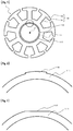
- Fig. 1 is a plan view illustrating a stator core 1.
- a core back 11 is an annular part around a central axis J1.
- the core back 11 has an inner peripheral surface 13 on an inner periphery in the radial direction.
- a plurality of teeth 12 radially extends outward in the radial direction from the core back 11.
- the plurality of teeth 12 is arranged at substantially regular intervals in the circumferential direction.
- Each of the teeth 12 includes a tooth body part 14 and a tooth tip part 15.
- the tooth body part 14 extends substantially linearly outward in the radial direction from the core back 11.
- the tooth tip part 15 extends to each side in the circumferential direction from an outer end of the tooth body part 14 in the radial direction.
- the core back 11 and the plurality of teeth 12 are, for example, a continuous metal member.
- a plastically deformable part 111 is provided to the core back 11 for joining stacked steel sheets.
- the plastically deformable part 111 is located below an upper end surface of the core back 11 in the axial direction in the core back 11.
- the plastically deformable part 111 has an annular shape around the central axis J1 and is an area including a part of the inner peripheral surface of the core back.
- the plastically deformable part 111 has a deformable part 112 which is an area having a different distance from the central axis J1. More specifically, the distance from the central axis J1 to the deformable part 112 that is at least a part of the outer periphery of the annular plastically deformable part 111 is different from the distance from the central axis J1 to the plastically deformable part 111. Note that the area having a different distance from the central axis J1 is not limited to be formed in one location of the plastically deformable part 111. Such area may be formed in two or more locations.
- the plastically deformable part 111 has a toric shape.
- the deformable part 112 which is the area having a different distance from the central axis J1
- a connecting portion between the deformable part 112 and the plastically deformable part 111 has a linear shape extending in the radial direction. However, it may have an arc shape.
- the deformable part 112 is not necessarily arcuate. For example, it may have a linear shape as shown in Fig. 3 , or may have an arc protruding inward in the radial direction as shown in Fig. 4 . Further, it may have a rectangular shape. In addition, the deformable part 112 is not limited to be provided in one location. A plurality of deformable parts may be provided, and the plastically deformable part 111 may be polygonal.
- the stator core 1 is manufactured by stacking steel sheets manufactured by press working.
- the plastically deformable part 111 may be formed every time the steel sheet is stacked in the manufacturing process, or may be formed after all the steel sheets constituting the stator core 1 are stacked.
- the steel sheets of the stator core 1 are stacked one by one, they are stacked with the deformable parts 112 overlapping each other in the axial direction, so that the deformable parts 112 function as a detent.
- the steel sheets may be stacked while being rotated at predetermined angle intervals. In this case, although depending on the angle of rotation, the steel sheets are stacked with at least a part of the deformable part 112 overlapping with the other portion of the plastically deformable part 111.
- the deformable part 112 is press-fitted into the plastically deformable part 111 as compared with a case where the steel sheets are simply stacked with the deformable parts 112 overlapping each other, the fixing strength between them is enhanced.
- the deformable part 112 is different in shape from the other portion of the plastically deformable part 111. Therefore, when the steel sheets constituting the stator core 1 are stacked while being rotated at predetermined angle intervals, they are fixed to each other.
- a distance D2 from the central axis J1 to the outer periphery of the deformable part 112 is larger than a distance D1 from the central axis J1 to the outer periphery of the plastically deformable part 111.
- the distance D2 from the central axis J1 to the outer periphery of the deformable part 112 may be smaller than the distance D1 from the central axis J1 to the outer periphery of the plastically deformable part 111.
- the deformable part 112 may have both an area where the distance D2 from the central axis J1 to the outer periphery of the deformable part 112 is greater than the distance D1 from the central axis J1 to the outer periphery of the plastically deformable part 111 and an area where the distance D2 is smaller than the distance D1.
- the annular plastically deformable part 111 is provided to the core back 11 for joining stacked steel sheets.
- the stacked steel sheets can be joined to each other, and distortion due to plastic deformation of the stator core can be suppressed.
- a part of the plastically deformable part 111 has a different distance from the central axis J1, it is possible to suppress displacement of the stator core. Since at least a part of the plastically deformable part 111 has a different distance from the central axis J1, it functions as a detent. Therefore, a motor having excellent motor characteristics and dimensional accuracy can be obtained.
- the plastically deformable part 111 has an annular shape around the central axis J1.
- the plastically deformable part 111 has a toric shape.
- At least a part of the plastically deformable part 111 having a toric shape is an arc having a diameter different from that of the plastically deformable part 111.
- the stator core 1 may be a skew core. In this case, displacement of skew is also suppressed, because at least a part of the plastically deformable part 111 has a different distance from the central axis J1. Thus, a motor having excellent motor characteristics and dimensional accuracy can be obtained.
- a shaft member such as a shaft or a bracket (not illustrated) may be fixed to the stator core 1.
- the shaft member is in contact with the inner peripheral surface of the core back 11 and is fixed by various methods such as adhesion, welding, and press fitting.
- stator core 1 may be used as a component constituting a motor. More specifically, the motor includes the stator core 1, a rotor centered on the central axis J1 and disposed outside the stator core, and a magnet fixed to the rotor and facing the stator core 1.
- stator core and the motor may be different from those illustrated in the drawings of the present application.
- components presented in the embodiment and the modification described above may be combined together, as appropriate, as long as there is no inconsistency.
- the present application can be used for a stator core and a motor.
Landscapes
- Engineering & Computer Science (AREA)
- Power Engineering (AREA)
- Iron Core Of Rotating Electric Machines (AREA)
- Manufacture Of Motors, Generators (AREA)
Abstract
Description
- The present invention relates to a stator core, a rotor core, and a motor.
- For example,
JP 2010-35328 A JP 2010-35328 A - Patent Literature 1:
JP 2010-35328 A - In the motor having such a configuration, crimping may not be performed at a tooth part for suppressing deformation of the tooth part. In this case, crimping is performed at a core back part, but when the core back part is plastically deformed by crimping or the like, the entire stator core may be distorted, which may adversely affect motor characteristics, dimensional accuracy, and the like.
- An object of the present invention is to provide a stator core having excellent motor characteristics and dimensional accuracy.
- A stator core according to the present invention is formed by stacking stacked steel sheets, and includes: a core back having an annular shape around a central axis; a plurality of teeth extending outward from the core back in a radial direction; and an inner peripheral surface located inside the core back in the radial direction and extending from an upper end to a lower end of the core back around the central axis. The core back includes a plastically deformable part that has an annular shape around the central axis and that is disposed below the core back in an axial direction. At least a part of the plastically deformable part has a different distance from the central axis.
- According to an aspect of the present invention, it is possible to provide a stator core excellent in motor characteristics and dimensional accuracy.
-
-
Fig. 1 is a plan view of a stator core according to a first embodiment. -
Fig. 2 is a partially enlarged view of the stator core according to the first embodiment. -
Fig. 3 is a partially enlarged view of a stator core according to a modification. -
Fig. 4 is a partially enlarged view of a stator core according to a modification. -
Fig. 5 is a cross-sectional view of the stator core according to the first embodiment. - An exemplary embodiment of the present application will be described below with reference to the accompanying drawings. In the present application, a direction parallel to a central axis of a stator core is referred to as an "axial direction", a direction perpendicular to a central axis of a strain wave gearing device is referred to as a "radial direction", and a direction along an arc about the central axis of the stator core is referred to as a "circumferential direction".
- In addition, a "parallel direction" in the present application includes a substantially parallel direction. Furthermore, an "orthogonal direction" in the present application includes a substantially orthogonal direction.
-
Fig. 1 is a plan view illustrating a stator core 1. Acore back 11 is an annular part around a central axis J1. Thecore back 11 has an innerperipheral surface 13 on an inner periphery in the radial direction. A plurality ofteeth 12 radially extends outward in the radial direction from thecore back 11. The plurality ofteeth 12 is arranged at substantially regular intervals in the circumferential direction. Each of theteeth 12 includes atooth body part 14 and atooth tip part 15. Thetooth body part 14 extends substantially linearly outward in the radial direction from thecore back 11. Thetooth tip part 15 extends to each side in the circumferential direction from an outer end of thetooth body part 14 in the radial direction. Thecore back 11 and the plurality ofteeth 12 are, for example, a continuous metal member. - In addition, a plastically
deformable part 111 is provided to thecore back 11 for joining stacked steel sheets. The plasticallydeformable part 111 is located below an upper end surface of thecore back 11 in the axial direction in thecore back 11. The plasticallydeformable part 111 has an annular shape around the central axis J1 and is an area including a part of the inner peripheral surface of the core back. - As illustrated in
Fig. 2 , at least a part of the plasticallydeformable part 111 has adeformable part 112 which is an area having a different distance from the central axis J1. More specifically, the distance from the central axis J1 to thedeformable part 112 that is at least a part of the outer periphery of the annular plasticallydeformable part 111 is different from the distance from the central axis J1 to the plasticallydeformable part 111. Note that the area having a different distance from the central axis J1 is not limited to be formed in one location of the plasticallydeformable part 111. Such area may be formed in two or more locations. - In the present embodiment, the plastically
deformable part 111 has a toric shape. In the plasticallydeformable part 111 having a toric shape, thedeformable part 112, which is the area having a different distance from the central axis J1, is an arc having a diameter different from that of the plasticallydeformable part 111. InFig. 2 , a connecting portion between thedeformable part 112 and the plasticallydeformable part 111 has a linear shape extending in the radial direction. However, it may have an arc shape. - Note that the
deformable part 112 is not necessarily arcuate. For example, it may have a linear shape as shown inFig. 3 , or may have an arc protruding inward in the radial direction as shown inFig. 4 . Further, it may have a rectangular shape. In addition, thedeformable part 112 is not limited to be provided in one location. A plurality of deformable parts may be provided, and the plasticallydeformable part 111 may be polygonal. - The stator core 1 is manufactured by stacking steel sheets manufactured by press working. The plastically
deformable part 111 may be formed every time the steel sheet is stacked in the manufacturing process, or may be formed after all the steel sheets constituting the stator core 1 are stacked. - As illustrated in
Fig. 5 , when the steel sheets of the stator core 1 are stacked one by one, they are stacked with thedeformable parts 112 overlapping each other in the axial direction, so that thedeformable parts 112 function as a detent. In order to suppress the eccentricity of the center of gravity or to stack the steel sheets askew, the steel sheets may be stacked while being rotated at predetermined angle intervals. In this case, although depending on the angle of rotation, the steel sheets are stacked with at least a part of thedeformable part 112 overlapping with the other portion of the plasticallydeformable part 111. In this case, since thedeformable part 112 is press-fitted into the plasticallydeformable part 111 as compared with a case where the steel sheets are simply stacked with thedeformable parts 112 overlapping each other, the fixing strength between them is enhanced. In addition, thedeformable part 112 is different in shape from the other portion of the plasticallydeformable part 111. Therefore, when the steel sheets constituting the stator core 1 are stacked while being rotated at predetermined angle intervals, they are fixed to each other. - In the present embodiment, a distance D2 from the central axis J1 to the outer periphery of the
deformable part 112 is larger than a distance D1 from the central axis J1 to the outer periphery of the plasticallydeformable part 111. Note that the distance D2 from the central axis J1 to the outer periphery of thedeformable part 112 may be smaller than the distance D1 from the central axis J1 to the outer periphery of the plasticallydeformable part 111. In addition, thedeformable part 112 may have both an area where the distance D2 from the central axis J1 to the outer periphery of thedeformable part 112 is greater than the distance D1 from the central axis J1 to the outer periphery of the plasticallydeformable part 111 and an area where the distance D2 is smaller than the distance D1. - As described above, the annular plastically
deformable part 111 is provided to the core back 11 for joining stacked steel sheets. Thus, the stacked steel sheets can be joined to each other, and distortion due to plastic deformation of the stator core can be suppressed. In addition, since a part of the plasticallydeformable part 111 has a different distance from the central axis J1, it is possible to suppress displacement of the stator core. Since at least a part of the plasticallydeformable part 111 has a different distance from the central axis J1, it functions as a detent. Therefore, a motor having excellent motor characteristics and dimensional accuracy can be obtained. - The plastically
deformable part 111 has an annular shape around the central axis J1. In the present embodiment, the plasticallydeformable part 111 has a toric shape. As a result, stress due to plastic deformation is uniformly applied, so that distortion is further suppressed. - At least a part of the plastically
deformable part 111 having a toric shape is an arc having a diameter different from that of the plasticallydeformable part 111. With this configuration, it is possible to suppress distortion while enhancing dimensional accuracy of the stator core 1. - The stator core 1 may be a skew core. In this case, displacement of skew is also suppressed, because at least a part of the plastically
deformable part 111 has a different distance from the central axis J1. Thus, a motor having excellent motor characteristics and dimensional accuracy can be obtained. - Note that a shaft member such as a shaft or a bracket (not illustrated) may be fixed to the stator core 1. The shaft member is in contact with the inner peripheral surface of the core back 11 and is fixed by various methods such as adhesion, welding, and press fitting.
- Note that the stator core 1 may be used as a component constituting a motor. More specifically, the motor includes the stator core 1, a rotor centered on the central axis J1 and disposed outside the stator core, and a magnet fixed to the rotor and facing the stator core 1.
- In addition, shapes and the like of details of the stator core and the motor may be different from those illustrated in the drawings of the present application. In addition, the components presented in the embodiment and the modification described above may be combined together, as appropriate, as long as there is no inconsistency.
- The present application can be used for a stator core and a motor.
-
- 1
- stator core
- 11
- core back
- 12
- tooth
- 13
- inner peripheral surface
- 14
- tooth body part
- 15
- tooth tip part
- 111
- plastically deformable part
- 112
- deformable part
Claims (8)
- A stator core formed by stacking stacked steel sheets, the stator core comprising:a core back having an annular shape around a central axis;a plurality of teeth extending outward from the core back in a radial direction; andan inner peripheral surface located inside the core back in the radial direction and extending from an upper end to a lower end of the core back around the central axis, wherein the core back includes a plastically deformable part that has an annular shape around the central axis and that is disposed below the core back in an axial direction, and at least a part of the plastically deformable part has a different distance from the central axis.
- The stator core according to claim 1, wherein the plastically deformable part (111) differs in distance from the central axis to an outer periphery in the radial direction.
- The stator core according to claim 1 or 2, wherein an inner peripheral surface of the plastically deformable part constitutes a part of the hole.
- The stator core according to any one of claims 1 to 3, wherein the plastically deformable part has a toric shape.
- The stator core according to claim 4, wherein at least a part of the plastically deformable part is an arc having a different diameter.
- The stator core according to any one of claims 1 to 5, wherein the stacked steel sheets are stacked askew.
- The stator core according to any one of claims 1 to 6, further comprising a columnar shaft fixed to the stator core and centered on the central axis, wherein the shaft has an outer peripheral surface that is in contact with the inner peripheral surface.
- A motor comprising:the stator core according to any one of claims 1 to 7; anda rotor disposed outside the stator core.
Applications Claiming Priority (2)
| Application Number | Priority Date | Filing Date | Title |
|---|---|---|---|
| JP2019028724 | 2019-02-20 | ||
| PCT/JP2020/003906 WO2020170782A1 (en) | 2019-02-20 | 2020-02-03 | Stator core, rotor core, and motor |
Publications (2)
| Publication Number | Publication Date |
|---|---|
| EP3930150A1 true EP3930150A1 (en) | 2021-12-29 |
| EP3930150A4 EP3930150A4 (en) | 2022-11-16 |
Family
ID=72143382
Family Applications (1)
| Application Number | Title | Priority Date | Filing Date |
|---|---|---|---|
| EP20759771.7A Pending EP3930150A4 (en) | 2019-02-20 | 2020-02-03 | Stator core, rotor core, and motor |
Country Status (5)
| Country | Link |
|---|---|
| US (1) | US11855486B2 (en) |
| EP (1) | EP3930150A4 (en) |
| JP (1) | JPWO2020170782A1 (en) |
| CN (1) | CN113454877B (en) |
| WO (1) | WO2020170782A1 (en) |
Families Citing this family (1)
| Publication number | Priority date | Publication date | Assignee | Title |
|---|---|---|---|---|
| US10602445B2 (en) | 2017-09-29 | 2020-03-24 | Mediatek Inc. | M2M semi-persistent scheduling in wireless communications |
Family Cites Families (13)
| Publication number | Priority date | Publication date | Assignee | Title |
|---|---|---|---|---|
| JP2583774B2 (en) * | 1987-12-25 | 1997-02-19 | ジーイー横河メディカルシステム株式会社 | High-speed numerical operation device |
| JPH0684552A (en) * | 1992-09-02 | 1994-03-25 | Toyota Motor Corp | Printed circuit device |
| JPH1169669A (en) * | 1997-08-25 | 1999-03-09 | Matsushita Electric Ind Co Ltd | DC brushless fan motor |
| DE19939528A1 (en) * | 1999-08-20 | 2001-02-22 | Bayerische Motoren Werke Ag | Electrical machine with a rotor and a stator |
| JP2003169431A (en) * | 2001-11-29 | 2003-06-13 | Hitachi Ltd | Electric motor |
| JP2003319587A (en) | 2002-04-19 | 2003-11-07 | Nippon Steel Corp | Rotor for low iron loss adduction motor and method of manufacturing the same |
| JP5211651B2 (en) * | 2007-11-15 | 2013-06-12 | パナソニック株式会社 | Motor and electronic device using the same |
| JP2010035328A (en) | 2008-07-29 | 2010-02-12 | Nippon Densan Corp | Design method and manufacturing method of core of stator, design method of assembly having motor, core of stator, motor and assembly having motor |
| JP5372629B2 (en) * | 2009-07-09 | 2013-12-18 | 日本電産株式会社 | Brushless motor |
| KR101079050B1 (en) * | 2009-07-21 | 2011-11-02 | 주식회사 아모텍 | Stator having structure of division type skew core, BLDC motor using the same, and battery cooling apparatus |
| JP5513070B2 (en) * | 2009-10-22 | 2014-06-04 | サムスン電機ジャパンアドバンスドテクノロジー株式会社 | Disk drive |
| JP6323146B2 (en) | 2014-04-26 | 2018-05-16 | 日本電産株式会社 | Motor and blower |
| JP2016129473A (en) | 2015-01-10 | 2016-07-14 | 日本電産株式会社 | motor |
-
2020
- 2020-02-03 WO PCT/JP2020/003906 patent/WO2020170782A1/en not_active Ceased
- 2020-02-03 EP EP20759771.7A patent/EP3930150A4/en active Pending
- 2020-02-03 JP JP2021501810A patent/JPWO2020170782A1/en active Pending
- 2020-02-03 US US17/429,682 patent/US11855486B2/en active Active
- 2020-02-03 CN CN202080014703.3A patent/CN113454877B/en active Active
Also Published As
| Publication number | Publication date |
|---|---|
| CN113454877A (en) | 2021-09-28 |
| CN113454877B (en) | 2024-07-23 |
| EP3930150A4 (en) | 2022-11-16 |
| WO2020170782A1 (en) | 2020-08-27 |
| US11855486B2 (en) | 2023-12-26 |
| JPWO2020170782A1 (en) | 2021-12-16 |
| US20220158508A1 (en) | 2022-05-19 |
Similar Documents
| Publication | Publication Date | Title |
|---|---|---|
| US11258341B2 (en) | Rotational electric machine rotor | |
| JP4602784B2 (en) | Fastening structure of motor rotor core and shaft | |
| JP5499776B2 (en) | Rotating electric machine | |
| JP6282340B2 (en) | Wave generator for wave gear device and method for manufacturing wave generator | |
| US20230208215A1 (en) | Rotating electrical machine | |
| JP2015112018A (en) | Press fit fixing method | |
| EP3891875A1 (en) | Squirrel-cage rotor | |
| CN101189780B (en) | Armature for rotating electric machine and manufacturing method thereof | |
| JP5638705B2 (en) | Electric motor laminated core | |
| US11855486B2 (en) | Stator core, rotor core, and motor | |
| WO2013121754A1 (en) | Stator core for motor and manufacturing method therefor | |
| JP2015082862A (en) | Fastening structure of rotor core and shaft of rotating electrical machine | |
| US8375562B2 (en) | Manufacturing method of rotating electric machine and rotating electric machine | |
| JP2013034335A (en) | Rotor structure of magnet-embedded motor | |
| JP7113906B2 (en) | Rotating electric machine | |
| JP6263330B2 (en) | Resolver rotor | |
| JP2008278597A (en) | Rotor core | |
| JP2010110123A (en) | Laminate core and manufacturing method thereof | |
| JP5809993B2 (en) | Rotating electric machine | |
| JP2014183631A (en) | Press-fit fixture structure | |
| US20260128630A1 (en) | Rotor for resolver and resolver | |
| JP6828307B2 (en) | How to manufacture rotors and motors | |
| JP6001504B2 (en) | Rotor body | |
| JP6910413B2 (en) | Rotating machine | |
| JP2011036094A (en) | Caulking jig |
Legal Events
| Date | Code | Title | Description |
|---|---|---|---|
| STAA | Information on the status of an ep patent application or granted ep patent |
Free format text: STATUS: THE INTERNATIONAL PUBLICATION HAS BEEN MADE |
|
| PUAI | Public reference made under article 153(3) epc to a published international application that has entered the european phase |
Free format text: ORIGINAL CODE: 0009012 |
|
| STAA | Information on the status of an ep patent application or granted ep patent |
Free format text: STATUS: REQUEST FOR EXAMINATION WAS MADE |
|
| 17P | Request for examination filed |
Effective date: 20210726 |
|
| AK | Designated contracting states |
Kind code of ref document: A1 Designated state(s): AL AT BE BG CH CY CZ DE DK EE ES FI FR GB GR HR HU IE IS IT LI LT LU LV MC MK MT NL NO PL PT RO RS SE SI SK SM TR |
|
| DAV | Request for validation of the european patent (deleted) | ||
| DAX | Request for extension of the european patent (deleted) | ||
| A4 | Supplementary search report drawn up and despatched |
Effective date: 20221014 |
|
| RIC1 | Information provided on ipc code assigned before grant |
Ipc: H02K 1/14 20060101ALI20221010BHEP Ipc: H02K 1/18 20060101AFI20221010BHEP |