EP3930101A1 - Kabelverlängerung für ein schiffsbatterieladegerät - Google Patents
Kabelverlängerung für ein schiffsbatterieladegerät Download PDFInfo
- Publication number
- EP3930101A1 EP3930101A1 EP21181752.3A EP21181752A EP3930101A1 EP 3930101 A1 EP3930101 A1 EP 3930101A1 EP 21181752 A EP21181752 A EP 21181752A EP 3930101 A1 EP3930101 A1 EP 3930101A1
- Authority
- EP
- European Patent Office
- Prior art keywords
- ring
- battery charger
- positive
- negative
- cover piece
- Prior art date
- Legal status (The legal status is an assumption and is not a legal conclusion. Google has not performed a legal analysis and makes no representation as to the accuracy of the status listed.)
- Granted
Links
Images


Classifications
-
- H—ELECTRICITY
- H01—ELECTRIC ELEMENTS
- H01R—ELECTRICALLY-CONDUCTIVE CONNECTIONS; STRUCTURAL ASSOCIATIONS OF A PLURALITY OF MUTUALLY-INSULATED ELECTRICAL CONNECTING ELEMENTS; COUPLING DEVICES; CURRENT COLLECTORS
- H01R31/00—Coupling parts supported only by co-operation with counterpart
- H01R31/06—Intermediate parts for linking two coupling parts, e.g. adapter
- H01R31/065—Intermediate parts for linking two coupling parts, e.g. adapter with built-in electric apparatus
-
- H—ELECTRICITY
- H02—GENERATION; CONVERSION OR DISTRIBUTION OF ELECTRIC POWER
- H02J—ELECTRIC POWER NETWORKS; CIRCUIT ARRANGEMENTS OR SYSTEMS FOR SUPPLYING OR DISTRIBUTING ELECTRIC POWER; SYSTEMS FOR STORING ELECTRIC ENERGY
- H02J7/00—Circuit arrangements for charging or discharging batteries or for supplying loads from batteries
- H02J7/70—Circuit arrangements for charging or discharging batteries or for supplying loads from batteries characterised by the mechanical construction
-
- H—ELECTRICITY
- H01—ELECTRIC ELEMENTS
- H01M—PROCESSES OR MEANS, e.g. BATTERIES, FOR THE DIRECT CONVERSION OF CHEMICAL ENERGY INTO ELECTRICAL ENERGY
- H01M10/00—Secondary cells; Manufacture thereof
- H01M10/42—Methods or arrangements for servicing or maintenance of secondary cells or secondary half-cells
- H01M10/46—Accumulators structurally combined with charging apparatus
-
- H—ELECTRICITY
- H01—ELECTRIC ELEMENTS
- H01R—ELECTRICALLY-CONDUCTIVE CONNECTIONS; STRUCTURAL ASSOCIATIONS OF A PLURALITY OF MUTUALLY-INSULATED ELECTRICAL CONNECTING ELEMENTS; COUPLING DEVICES; CURRENT COLLECTORS
- H01R11/00—Individual connecting elements providing two or more spaced connecting locations for conductive members which are, or may be, thereby interconnected, e.g. end pieces for wires or cables supported by the wire or cable and having means for facilitating electrical connection to some other wire, terminal, or conductive member, blocks of binding posts
- H01R11/11—End pieces or tapping pieces for wires, supported by the wire and for facilitating electrical connection to some other wire, terminal or conductive member
- H01R11/12—End pieces terminating in an eye, hook, or fork
-
- H—ELECTRICITY
- H01—ELECTRIC ELEMENTS
- H01R—ELECTRICALLY-CONDUCTIVE CONNECTIONS; STRUCTURAL ASSOCIATIONS OF A PLURALITY OF MUTUALLY-INSULATED ELECTRICAL CONNECTING ELEMENTS; COUPLING DEVICES; CURRENT COLLECTORS
- H01R11/00—Individual connecting elements providing two or more spaced connecting locations for conductive members which are, or may be, thereby interconnected, e.g. end pieces for wires or cables supported by the wire or cable and having means for facilitating electrical connection to some other wire, terminal, or conductive member, blocks of binding posts
- H01R11/11—End pieces or tapping pieces for wires, supported by the wire and for facilitating electrical connection to some other wire, terminal or conductive member
- H01R11/26—End pieces terminating in a screw clamp, screw or nut
-
- H—ELECTRICITY
- H01—ELECTRIC ELEMENTS
- H01R—ELECTRICALLY-CONDUCTIVE CONNECTIONS; STRUCTURAL ASSOCIATIONS OF A PLURALITY OF MUTUALLY-INSULATED ELECTRICAL CONNECTING ELEMENTS; COUPLING DEVICES; CURRENT COLLECTORS
- H01R11/00—Individual connecting elements providing two or more spaced connecting locations for conductive members which are, or may be, thereby interconnected, e.g. end pieces for wires or cables supported by the wire or cable and having means for facilitating electrical connection to some other wire, terminal, or conductive member, blocks of binding posts
- H01R11/11—End pieces or tapping pieces for wires, supported by the wire and for facilitating electrical connection to some other wire, terminal or conductive member
- H01R11/28—End pieces consisting of a ferrule or sleeve
- H01R11/281—End pieces consisting of a ferrule or sleeve for connections to batteries
-
- H—ELECTRICITY
- H01—ELECTRIC ELEMENTS
- H01R—ELECTRICALLY-CONDUCTIVE CONNECTIONS; STRUCTURAL ASSOCIATIONS OF A PLURALITY OF MUTUALLY-INSULATED ELECTRICAL CONNECTING ELEMENTS; COUPLING DEVICES; CURRENT COLLECTORS
- H01R13/00—Details of coupling devices of the kinds covered by groups H01R12/70 or H01R24/00 - H01R33/00
- H01R13/46—Bases; Cases
- H01R13/52—Dustproof, splashproof, drip-proof, waterproof, or flameproof cases
- H01R13/5213—Covers
-
- H—ELECTRICITY
- H01—ELECTRIC ELEMENTS
- H01R—ELECTRICALLY-CONDUCTIVE CONNECTIONS; STRUCTURAL ASSOCIATIONS OF A PLURALITY OF MUTUALLY-INSULATED ELECTRICAL CONNECTING ELEMENTS; COUPLING DEVICES; CURRENT COLLECTORS
- H01R13/00—Details of coupling devices of the kinds covered by groups H01R12/70 or H01R24/00 - H01R33/00
- H01R13/62—Means for facilitating engagement or disengagement of coupling parts or for holding them in engagement
- H01R13/621—Bolt, set screw or screw clamp
-
- H—ELECTRICITY
- H01—ELECTRIC ELEMENTS
- H01R—ELECTRICALLY-CONDUCTIVE CONNECTIONS; STRUCTURAL ASSOCIATIONS OF A PLURALITY OF MUTUALLY-INSULATED ELECTRICAL CONNECTING ELEMENTS; COUPLING DEVICES; CURRENT COLLECTORS
- H01R13/00—Details of coupling devices of the kinds covered by groups H01R12/70 or H01R24/00 - H01R33/00
- H01R13/62—Means for facilitating engagement or disengagement of coupling parts or for holding them in engagement
- H01R13/629—Additional means for facilitating engagement or disengagement of coupling parts, e.g. aligning or guiding means, levers, gas pressure electrical locking indicators, manufacturing tolerances
-
- H—ELECTRICITY
- H01—ELECTRIC ELEMENTS
- H01R—ELECTRICALLY-CONDUCTIVE CONNECTIONS; STRUCTURAL ASSOCIATIONS OF A PLURALITY OF MUTUALLY-INSULATED ELECTRICAL CONNECTING ELEMENTS; COUPLING DEVICES; CURRENT COLLECTORS
- H01R13/00—Details of coupling devices of the kinds covered by groups H01R12/70 or H01R24/00 - H01R33/00
- H01R13/62—Means for facilitating engagement or disengagement of coupling parts or for holding them in engagement
- H01R13/639—Additional means for holding or locking coupling parts together, after engagement, e.g. separate keylock, retainer strap
-
- H—ELECTRICITY
- H01—ELECTRIC ELEMENTS
- H01R—ELECTRICALLY-CONDUCTIVE CONNECTIONS; STRUCTURAL ASSOCIATIONS OF A PLURALITY OF MUTUALLY-INSULATED ELECTRICAL CONNECTING ELEMENTS; COUPLING DEVICES; CURRENT COLLECTORS
- H01R13/00—Details of coupling devices of the kinds covered by groups H01R12/70 or H01R24/00 - H01R33/00
- H01R13/66—Structural association with built-in electrical component
- H01R13/68—Structural association with built-in electrical component with built-in fuse
-
- H—ELECTRICITY
- H01—ELECTRIC ELEMENTS
- H01R—ELECTRICALLY-CONDUCTIVE CONNECTIONS; STRUCTURAL ASSOCIATIONS OF A PLURALITY OF MUTUALLY-INSULATED ELECTRICAL CONNECTING ELEMENTS; COUPLING DEVICES; CURRENT COLLECTORS
- H01R31/00—Coupling parts supported only by co-operation with counterpart
- H01R31/06—Intermediate parts for linking two coupling parts, e.g. adapter
-
- H—ELECTRICITY
- H02—GENERATION; CONVERSION OR DISTRIBUTION OF ELECTRIC POWER
- H02G—INSTALLATION OF ELECTRIC CABLES OR LINES, OR OF COMBINED OPTICAL AND ELECTRIC CABLES OR LINES
- H02G11/00—Arrangements of electric cables or lines between relatively-movable parts
-
- H—ELECTRICITY
- H02—GENERATION; CONVERSION OR DISTRIBUTION OF ELECTRIC POWER
- H02J—ELECTRIC POWER NETWORKS; CIRCUIT ARRANGEMENTS OR SYSTEMS FOR SUPPLYING OR DISTRIBUTING ELECTRIC POWER; SYSTEMS FOR STORING ELECTRIC ENERGY
- H02J7/00—Circuit arrangements for charging or discharging batteries or for supplying loads from batteries
- H02J7/485—Circuit arrangements for charging or discharging batteries or for supplying loads from batteries with provisions for charging different types of batteries
-
- H—ELECTRICITY
- H02—GENERATION; CONVERSION OR DISTRIBUTION OF ELECTRIC POWER
- H02J—ELECTRIC POWER NETWORKS; CIRCUIT ARRANGEMENTS OR SYSTEMS FOR SUPPLYING OR DISTRIBUTING ELECTRIC POWER; SYSTEMS FOR STORING ELECTRIC ENERGY
- H02J7/00—Circuit arrangements for charging or discharging batteries or for supplying loads from batteries
- H02J7/70—Circuit arrangements for charging or discharging batteries or for supplying loads from batteries characterised by the mechanical construction
- H02J7/751—Circuit arrangements for charging or discharging batteries or for supplying loads from batteries characterised by the mechanical construction concerning the insertion or the connection of the batteries
-
- H—ELECTRICITY
- H01—ELECTRIC ELEMENTS
- H01R—ELECTRICALLY-CONDUCTIVE CONNECTIONS; STRUCTURAL ASSOCIATIONS OF A PLURALITY OF MUTUALLY-INSULATED ELECTRICAL CONNECTING ELEMENTS; COUPLING DEVICES; CURRENT COLLECTORS
- H01R13/00—Details of coupling devices of the kinds covered by groups H01R12/70 or H01R24/00 - H01R33/00
- H01R13/46—Bases; Cases
- H01R13/502—Bases; Cases composed of different pieces
- H01R13/506—Bases; Cases composed of different pieces assembled by snap action of the parts
-
- H—ELECTRICITY
- H01—ELECTRIC ELEMENTS
- H01R—ELECTRICALLY-CONDUCTIVE CONNECTIONS; STRUCTURAL ASSOCIATIONS OF A PLURALITY OF MUTUALLY-INSULATED ELECTRICAL CONNECTING ELEMENTS; COUPLING DEVICES; CURRENT COLLECTORS
- H01R4/00—Electrically-conductive connections between two or more conductive members in direct contact, i.e. touching one another; Means for effecting or maintaining such contact; Electrically-conductive connections having two or more spaced connecting locations for conductors and using contact members penetrating insulation
- H01R4/28—Clamped connections, spring connections
- H01R4/30—Clamped connections, spring connections utilising a screw or nut clamping member
- H01R4/302—Clamped connections, spring connections utilising a screw or nut clamping member having means for preventing loosening of screw or nut, e.g. vibration-proof connection
-
- H—ELECTRICITY
- H02—GENERATION; CONVERSION OR DISTRIBUTION OF ELECTRIC POWER
- H02J—ELECTRIC POWER NETWORKS; CIRCUIT ARRANGEMENTS OR SYSTEMS FOR SUPPLYING OR DISTRIBUTING ELECTRIC POWER; SYSTEMS FOR STORING ELECTRIC ENERGY
- H02J2105/00—Networks for supplying or distributing electric power characterised by their spatial reach or by the load
- H02J2105/30—Networks for supplying or distributing electric power characterised by their spatial reach or by the load the load networks being external to vehicles, i.e. exchanging power with vehicles
- H02J2105/31—Networks for supplying or distributing electric power characterised by their spatial reach or by the load the load networks being external to vehicles, i.e. exchanging power with vehicles for ships or vessels
-
- Y—GENERAL TAGGING OF NEW TECHNOLOGICAL DEVELOPMENTS; GENERAL TAGGING OF CROSS-SECTIONAL TECHNOLOGIES SPANNING OVER SEVERAL SECTIONS OF THE IPC; TECHNICAL SUBJECTS COVERED BY FORMER USPC CROSS-REFERENCE ART COLLECTIONS [XRACs] AND DIGESTS
- Y02—TECHNOLOGIES OR APPLICATIONS FOR MITIGATION OR ADAPTATION AGAINST CLIMATE CHANGE
- Y02E—REDUCTION OF GREENHOUSE GAS [GHG] EMISSIONS, RELATED TO ENERGY GENERATION, TRANSMISSION OR DISTRIBUTION
- Y02E60/00—Enabling technologies; Technologies with a potential or indirect contribution to GHG emissions mitigation
- Y02E60/10—Energy storage using batteries
Definitions
- the present application is generally directed to marine battery charger systems, and more particularly to a cable extender for a pre-wired marine battery charger installed on a marine vessel.
- Marine vessels have electrical systems powered by one or more batteries storing electrical power on the marine vessel.
- the batteries require charging and an onboard marine battery charging system are the safest and most convenient way to charge and maintain those batteries.
- a marine battery charger cable extender includes a terminal end that has a positive extender ring terminal and a negative extender ring terminal, and a connection end configured to connect to a terminal end of a pre-wired battery charger.
- the connection end includes a positive ring end, a positive ring connector configured to hold the positive ring end in galvanic connection with a positive ring terminal of the pre-wired battery charger, and a positive connection cover configured to completely encapsulate the connected positive ring end of the cable extender and the positive ring terminal of the pre-wired battery charger.
- connection end also includes a negative ring end, a negative ring connector configured to hold the negative ring end in galvanic connection with a negative ring terminal of the pre-wired battery charger, and a negative connection cover configured to completely encapsulate the connected negative ring end of the cable extender and the negative ring terminal of the pre-wired battery charger.
- a marine battery charger cable extender includes a terminal end having a positive extender ring terminal configured to connect to a positive battery terminal and a negative extender ring terminal configured to connect to a negative battery terminal, and a connection end configured to connect to a terminal end of a pre-wired battery charger.
- the connection end includes a positive ring end, a positive ring connector including a first metal screw configured to hold the positive ring end in galvanic connection with a positive ring terminal of the pre-wired battery charger, and a positive connection cover configured to completely encapsulate the connected positive ring end of the cable extender and the positive ring terminal of the pre-wired battery charger.
- connection end further includes a negative ring end, a negative ring connecter including a second metal screw configured to hold the negative ring end in galvanic connection with a negative ring terminal of the pre-wired battery charger, and a negative connection cover configured to completely encapsulate the connected negative ring end of the cable extender and the negative ring terminal of the pre-wired battery charger.
- Each of the positive connection cover and the negative connection cover are formed by a first cover piece and a second cover piece releasably connected together.
- Marine battery chargers come pre-wired because the connection between the battery charger and the cable wire must be sealed into the body of the charger in a waterproof way so that water cannot penetrate and reach the electrical connection.
- Available pre-wired battery chargers come with a standard six foot cable.
- the present inventors have recognized that pre-wired battery chargers to be installed onboard marine vessels often need to be installed some distance away from the batteries they are charging, which is sometimes more than six feet and thus the cable wires of the pre-wired battery charger to do not reach one or more of the batteries that they are meant to charge.
- the inventors have recognized that, in order to accommodate the additional distance, people often extend the cable wires of the pre-wired battery chargers in unsafe ways. For example, people may cut the fuses off and solder extension wires directly to the cables on the charger. This can be a fire hazard and does not meet minimum boating safety standards.
- Prior art extenders do exist but have not offered easy and reliable means for connecting the cable extender to the terminal ends of the pre-wired battery charger in a way that sufficiently protects and maintains the connection and can withstand the wet and harsh conditions on a marine vessel.
- prior cable extenders do not provide sufficiently tight connections between the ring terminals of the pre-wired charger and the terminals of the cable extender.
- prior art systems do not sufficiently protect that connection from short circuit caused by conductive elements such as fish hooks or loose tools.
- the inventors have recognized that problems exist with current cable extenders and that the connections between the ring terminals loosen overtime.
- the inventors developed the disclosed system and method that, in certain embodiments, provides a metal ring connector to connect the ring terminal of the pre-wired marine charger to the ring connectors of the cable extender so as to provide a tight and durable connection that can withstand vibrations in the harsh marine environment.
- the disclosed cable extender includes a connection cover over each of the positive and negative ring connections, where the connection cover is configured to completely encapsulate the ring connections between the cable extender and the terminal end of the pre-wired battery charger.
- the connection is removable for purposes of maintenance and the entire system is reusable.
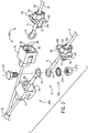
- Fig. 1 depicts one embodiment of a cable extender 20 for a pre-wired marine battery charger 9.
- the pre-wired marine battery charger 9 includes a battery charger 10 connected by a waterproof seal to a cable 12, which is a standard six foot cable.
- the cable 12 includes a negative cable wire 13 that terminates at a negative ring terminal 14, and a positive cable wire 15 that terminates at a positive ring terminal 16.
- Each of the positive and negative cable wires 13, 15 includes a fuse 18a, 18b, as is standard on marine battery chargers.
- the cable extender 20 has a connection end 32 that connects to the ring terminals 14, 16 of the pre-wired battery charger 9, and a terminal end 30 that includes a negative extender ring terminal 28 and a positive extender ring terminal 29 that are configured to connect to the positive and negative terminals of a battery installed on the marine vessel.
- the cable extender 20 includes a negative extender wire 21 and a positive extender wire 22 that extend from the connection end 32 to a respective fuse 25a, 25b.
- a terminal end 23 of the negative extender wire 23 connects between the fuse 25a and the negative extender ring terminal 28.
- a terminal end 24 of the positive extender wire connects between the fuse 25b and the positive extender ring terminal 29.
- a negative ring connector 37 is configured to hold the negative ring end 26 of the cable extender 20 to the negative ring terminal 14 of the pre-wired battery charger 9.
- a positive ring connector 38 is configured to hold the positive ring end 27 of the cable extender 20 to the positive ring terminal 16 of the pre-wired battery charger 9.
- each of the positive and negative ring connectors 37, 38 include a metal screw 371 configured to pass through the respective rings so as to connect them.
- a metal washer 372 and metal nut 373 are configured to connect to a bottom end of the metal screw 371 and tighten the rings 26 and 14 together so as to maintain galvanic connection between them.
- the metal washer 372 may be, for example, a lock washer, which helps prevent vibration.
- the ring connectors 37 and 38 may be other connection elements or means capable of connecting the respective rings, which are preferably devices that do not deform over time and or apply decreasing force on the rings to maintain the connection.
- the ring connectors 37 and 38 may be metal clips or clamps, such as a spring loaded clamp.
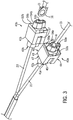
- Connection covers 40a and 40b cover each ring connecter in orderto protect the connection from the elements.
- a negative connection cover 40a is configured to encapsulate the connected negative ring end 26 and the negative ring terminal 14 of the pre-wired battery charger 9.
- the positive connection cover 40b is configured to encapsulate the connected positive ring end 27 with the positive ring terminal 16 of the pre-wired battery charger 9.
- Each of the negative and positive connection covers 40a, 40b may be a two-piece element where one of the cover pieces is placed on the connection end 32 of the cable extender 20 and the second cover piece is placed on the terminal end of the pre-wired battery charger.
- a first cover piece 41 is configured to fit over each of the positive and negative ring ends 26, 27.
- a second cover piece 52 is configured to fit over each of the negative and positive ring terminals 14, 16 of the pre-wired battery charger 9.
- Each first cover piece 41 is configured to releasably connect with the second cover piece 52 on the corresponding connection terminal without removing the ring terminal, as described herein.
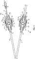
- Fig. 3 shows the first cover piece 41 and the second cover piece 52 connected together to form each of the negative connection cover 40a and the positive connection cover 40b.
- Fig. 4 depicts a cross-sectional view of each connection cover along cross-sectional indicator A of Fig. 3 .
- the connection covers 40a and 40b are each generally cube-shaped and formed by connection of the two releasably connectable pieces.
- the first cover piece 41 is configured to substantially cover the respective ring end 26, 27 and ring connector 37, 38
- the second cover piece 52 has a much narrower depth and is configured to connect at an open end 50 ( Fig. 2 ) of the first cover piece 41 in order to provide the second end portion 59 of the cube that encapsulates the connection.
- each cover piece has a top portion 43 and a bottom portion 44 which form opposing sides of the cube shape, and also include a first side portion 45 and a second side portion 46 that form adjacent opposing sides.
- the first cover piece 41 that fits over the ring end 37 or 38 of the cable extender 20 has a first end portion 47.
- the second end portion 59 of the connection cover 40 is formed by the second cover piece 52 that fits over the positive ring terminal.
- first cover piece 41 and the second cover piece 52 releasably connect together to form a cube shape that completely encapsulates the respective positive or negative connection between the ring terminal end (including over any heat shrink or insulating layer(s)) of the pre-wired battery charger 9 and the connection end 32 of the cable extender 20.
- each connection cover 40 may be connected by a clasp 56 configure to releasably connect the two cover pieces together.
- Figs. 2-4 depict an exemplary embodiment of the clasp 56, which in the depicted example is positioned on the second cover piece 52 and is configured to releasably connect to a clasping edge 49 on the first cover piece 41.
- each second cover piece 52 has two clasps 56, including a first clasp 56' on a first side portion 65 and a second clasp 56" on a second side portion 66.
- first cover portion 41 and the second cover portion 42 are made of a plastic material, such as a molded plastic material, and each clasp 56 is configured to be slightly deformable such that the clasp can slide into connection with the clasping edge 49 of the first cover piece 41.
- the clasp system on the connection cover provides a low-cost, tool-less installation means.
- the clasp 56 may have a clasp edge 57 that extends outward therefrom and maybe configured to slide in grooves 48 ( Fig. 2 ) on an inner-side of each of the first side portion 45 and the second side portion 46 of the first cover piece 41.
- the deformable clasps 56 are configured to bend slightly inward as each clasp 56 slides in the grooves 48.
- An opening or indentation in the respective side portion 45, 46 accommodates the clasp edge 57, such that the clasp 56 returns to its normal condition forcing the clasp edge 57 into opposition with the clasping edge 49 of the first cover piece 41 so as to connect the cover pieces together.
- a user can depress each clasp edge 57 on either side of the connection cover 40 so as to deform the clasp 56 and allow the second cover piece 52 to be pulled away from the first cover piece 41.
- the clasp 56 may be any mechanism for connecting the connecting the cover pieces 41 and 52, and particularly for connecting two molded plastic pieces together.
- the clasp may be on an exterior face of the first cover piece 41 or the second cover piece 52, and in such an embodiment, the clasping edge 49 would likewise be on an exterior face of the opposing cover piece 41, 52.
- the clasping edge 49 may be inward-extending, and thus an indentation or groove in the respective side portion, or may be an outward-extending edge, such as a distended ledge molded on the plastic piece.
- a person having ordinary skill in the art will understand in view of the present disclosure that many embodiments of the clasp 56 and clasping edge 49 are within the scope of the present disclosure.
- each connection cover 40 has a collar 54 extending from each of the first end portion 47 and the second end portion 59.
- the collar 54 is best shown in Fig. 5 .
- the collar 54 may be configured to surround an opening 53 in each end portion 47, 59 of the connection cover 40 so as to reduce ingress of debris into the area inside of the connection cover 40 and protect the ring terminal from abrasion or short circuit.
- Each opening 53 is configured to allow one of the rings 14, 16, 26, 27 to slide through the end portion 47, 59 of the respective cover piece 41, 52. In other words, the opening 53 is configured to allow the cover piece 41/52 to slide over the ring.
- the opening 53 may be configured such that it only allows insertion of the ring at certain angles and thus is configured to prevent the ring from easily pulling back through the opening 53.
- the opening 53 may have an elongated portion 73 having a length L configured to accommodate ring diameter D ( Fig. 3 ).
- the respective ring 14, 16, 26, 27 is turned 90 degrees from the connection angle at which it is connected via the ring connector, such as shown in Figs. 2 and 3 , to be inserted through the end portion 47, 59 of the respective cover piece 41, 52.
- the ring can then be turned back 90 degrees in order to maintain that cover piece 41, 52 in the connection cover 40.
- the opening 53 and collar 54 may further include a rounded portion 75 having an opening diameter W and configured to accommodate a joint 70 where the ring 14, 16, 26, 27 connects to the respective wire 13, 15, 21, 22.
- the rounded portion 75 bisects the elongated portion 73, and is configured in a position that aligns the respective cover piece 41, 52 appropriately for releasably connecting to the opposing cover piece 52, 41.
- the term bisect is used to refer to the position of the rounded portion 75 somewhere between a top end and bottom end of the elongated portion 73.
- a joint cover 71 provides a plastic barrier over the joint 70 so as to keep it protected from short circuits.
- the joint cover 71 may have a diameter C ( Fig.
- the width W is greater than the diameter C of the joint cover 71 so as to enable the respective cover piece 41, 52 to slide over the joint 70.
- the collar 54 has a depth P sufficiently long to cover the joint 70 to provide additional support and protection for the joint 70 area.
Landscapes
- Engineering & Computer Science (AREA)
- Power Engineering (AREA)
- Manufacturing & Machinery (AREA)
- Chemical & Material Sciences (AREA)
- Chemical Kinetics & Catalysis (AREA)
- Electrochemistry (AREA)
- General Chemical & Material Sciences (AREA)
- Details Of Connecting Devices For Male And Female Coupling (AREA)
- Charge And Discharge Circuits For Batteries Or The Like (AREA)
- Connector Housings Or Holding Contact Members (AREA)
Applications Claiming Priority (1)
| Application Number | Priority Date | Filing Date | Title |
|---|---|---|---|
| US16/913,095 US11757295B2 (en) | 2020-06-26 | 2020-06-26 | Marine battery charger cable expender |
Publications (3)
| Publication Number | Publication Date |
|---|---|
| EP3930101A1 true EP3930101A1 (de) | 2021-12-29 |
| EP3930101B1 EP3930101B1 (de) | 2024-02-28 |
| EP3930101C0 EP3930101C0 (de) | 2024-02-28 |
Family
ID=76641607
Family Applications (1)
| Application Number | Title | Priority Date | Filing Date |
|---|---|---|---|
| EP21181752.3A Active EP3930101B1 (de) | 2020-06-26 | 2021-06-25 | Kabelverlängerung für ein schiffsbatterieladegerät |
Country Status (3)
| Country | Link |
|---|---|
| US (1) | US11757295B2 (de) |
| EP (1) | EP3930101B1 (de) |
| CN (1) | CN113922175A (de) |
Families Citing this family (1)
| Publication number | Priority date | Publication date | Assignee | Title |
|---|---|---|---|---|
| US20240283199A1 (en) | 2023-02-22 | 2024-08-22 | Brunswick Corporation | Connector for battery connection to charger |
Citations (6)
| Publication number | Priority date | Publication date | Assignee | Title |
|---|---|---|---|---|
| US20030178949A1 (en) * | 2002-03-20 | 2003-09-25 | Yazaki Corporation | Arc discharge preventing device |
| US20050070155A1 (en) * | 2003-01-17 | 2005-03-31 | Horenstein Randy J. | Jumper cable system, jumper cable system kit, and battery charging system |
| US20050186814A1 (en) * | 2004-02-19 | 2005-08-25 | Thomas Vogel | Electrical connector for shielded cables |
| KR200430965Y1 (ko) * | 2006-08-30 | 2006-11-14 | 경신공업 주식회사 | 케이블의 통전장치 |
| US20180186036A1 (en) * | 2015-07-10 | 2018-07-05 | Autonetworks Technologies, Ltd. | Molded resin-equipped electric wire and molded resin-equipped electric wire production method |
| US20190168694A1 (en) * | 2017-12-06 | 2019-06-06 | Yazaki Corporation | Wiring Member Connection Structure |
Family Cites Families (6)
| Publication number | Priority date | Publication date | Assignee | Title |
|---|---|---|---|---|
| US20020100652A1 (en) * | 2001-01-31 | 2002-08-01 | Loyd Travis G. | Retractable cord assembly for use in marine vessels |
| US8234760B2 (en) * | 2007-11-28 | 2012-08-07 | Dr. V's Life Plan, Inc. | Mechanical zipper assist |
| DE102008010352A1 (de) * | 2008-02-13 | 2009-08-20 | Newfrey Llc, Newark | Halteanordnung für Kabelschuhe |
| US9559473B2 (en) * | 2014-04-15 | 2017-01-31 | Connect-Ease L. L. C. | Multi-battery and multi-device connection system |
| CN207338786U (zh) * | 2017-08-02 | 2018-05-08 | 孔和琴 | 一种通信电缆用旋转连接头 |
| CN208111714U (zh) * | 2018-05-25 | 2018-11-16 | 兰普电器股份有限公司 | 接线箱 |
-
2020
- 2020-06-26 US US16/913,095 patent/US11757295B2/en active Active
-
2021
- 2021-06-25 EP EP21181752.3A patent/EP3930101B1/de active Active
- 2021-06-25 CN CN202110712199.0A patent/CN113922175A/zh active Pending
Patent Citations (6)
| Publication number | Priority date | Publication date | Assignee | Title |
|---|---|---|---|---|
| US20030178949A1 (en) * | 2002-03-20 | 2003-09-25 | Yazaki Corporation | Arc discharge preventing device |
| US20050070155A1 (en) * | 2003-01-17 | 2005-03-31 | Horenstein Randy J. | Jumper cable system, jumper cable system kit, and battery charging system |
| US20050186814A1 (en) * | 2004-02-19 | 2005-08-25 | Thomas Vogel | Electrical connector for shielded cables |
| KR200430965Y1 (ko) * | 2006-08-30 | 2006-11-14 | 경신공업 주식회사 | 케이블의 통전장치 |
| US20180186036A1 (en) * | 2015-07-10 | 2018-07-05 | Autonetworks Technologies, Ltd. | Molded resin-equipped electric wire and molded resin-equipped electric wire production method |
| US20190168694A1 (en) * | 2017-12-06 | 2019-06-06 | Yazaki Corporation | Wiring Member Connection Structure |
Also Published As
| Publication number | Publication date |
|---|---|
| EP3930101B1 (de) | 2024-02-28 |
| EP3930101C0 (de) | 2024-02-28 |
| US20210408811A1 (en) | 2021-12-30 |
| CN113922175A (zh) | 2022-01-11 |
| US11757295B2 (en) | 2023-09-12 |
Similar Documents
| Publication | Publication Date | Title |
|---|---|---|
| US8517768B2 (en) | Breakaway fuse holder | |
| US9601865B2 (en) | Closure seal for electrical adaptor | |
| US8338710B2 (en) | Short-preventing shield for wire harness terminals | |
| US9559473B2 (en) | Multi-battery and multi-device connection system | |
| WO2007143603A2 (en) | Electrical connector with plug tether assembly and related methods | |
| US3519977A (en) | High amperage quick disconnect electric coupling structure | |
| WO2016069095A1 (en) | Battery tap electrical connector | |
| JP2014514906A (ja) | ケーブル終端装置 | |
| EP3930101B1 (de) | Kabelverlängerung für ein schiffsbatterieladegerät | |
| US6010804A (en) | Protective cover and connection device for batteries | |
| US8545256B2 (en) | Electrical connector for use with NATO equipment | |
| US3795891A (en) | Battery terminal | |
| US20130293184A1 (en) | Jumper cable | |
| JP5118433B2 (ja) | 水中ケーブル用コネクタ | |
| US4759728A (en) | Vehicle battery jumper improvement | |
| US20180083466A1 (en) | Multi-battery and multi-device connection system | |
| JP2011233440A (ja) | コネクタのケーブル接続部構造 | |
| EP0520291B1 (de) | Elektrisches Anschlussteil | |
| JP6706863B2 (ja) | ケーブル牽引構造及びケーブル端末 | |
| JP4107993B2 (ja) | 防水コネクタ | |
| JP5294665B2 (ja) | 電線端末キャップ | |
| JP3910689B2 (ja) | 電力ケーブルの端末/接続処理具および端末/接続部の組立方法 | |
| JPS6340852Y2 (de) | ||
| JP2004164958A (ja) | シールド機能を備えた導電路 | |
| KR102895446B1 (ko) | 와이어 하네스 프로텍터 |
Legal Events
| Date | Code | Title | Description |
|---|---|---|---|
| PUAI | Public reference made under article 153(3) epc to a published international application that has entered the european phase |
Free format text: ORIGINAL CODE: 0009012 |
|
| STAA | Information on the status of an ep patent application or granted ep patent |
Free format text: STATUS: THE APPLICATION HAS BEEN PUBLISHED |
|
| AK | Designated contracting states |
Kind code of ref document: A1 Designated state(s): AL AT BE BG CH CY CZ DE DK EE ES FI FR GB GR HR HU IE IS IT LI LT LU LV MC MK MT NL NO PL PT RO RS SE SI SK SM TR |
|
| B565 | Issuance of search results under rule 164(2) epc |
Effective date: 20211122 |
|
| STAA | Information on the status of an ep patent application or granted ep patent |
Free format text: STATUS: REQUEST FOR EXAMINATION WAS MADE |
|
| 17P | Request for examination filed |
Effective date: 20220627 |
|
| RBV | Designated contracting states (corrected) |
Designated state(s): AL AT BE BG CH CY CZ DE DK EE ES FI FR GB GR HR HU IE IS IT LI LT LU LV MC MK MT NL NO PL PT RO RS SE SI SK SM TR |
|
| P01 | Opt-out of the competence of the unified patent court (upc) registered |
Effective date: 20230330 |
|
| GRAP | Despatch of communication of intention to grant a patent |
Free format text: ORIGINAL CODE: EPIDOSNIGR1 |
|
| STAA | Information on the status of an ep patent application or granted ep patent |
Free format text: STATUS: GRANT OF PATENT IS INTENDED |
|
| INTG | Intention to grant announced |
Effective date: 20230818 |
|
| GRAS | Grant fee paid |
Free format text: ORIGINAL CODE: EPIDOSNIGR3 |
|
| GRAA | (expected) grant |
Free format text: ORIGINAL CODE: 0009210 |
|
| STAA | Information on the status of an ep patent application or granted ep patent |
Free format text: STATUS: THE PATENT HAS BEEN GRANTED |
|
| AK | Designated contracting states |
Kind code of ref document: B1 Designated state(s): AL AT BE BG CH CY CZ DE DK EE ES FI FR GB GR HR HU IE IS IT LI LT LU LV MC MK MT NL NO PL PT RO RS SE SI SK SM TR |
|
| REG | Reference to a national code |
Ref country code: GB Ref legal event code: FG4D |
|
| REG | Reference to a national code |
Ref country code: CH Ref legal event code: EP |
|
| REG | Reference to a national code |
Ref country code: DE Ref legal event code: R096 Ref document number: 602021009760 Country of ref document: DE |
|
| REG | Reference to a national code |
Ref country code: IE Ref legal event code: FG4D |
|
| U01 | Request for unitary effect filed |
Effective date: 20240229 |
|
| U07 | Unitary effect registered |
Designated state(s): AT BE BG DE DK EE FI FR IT LT LU LV MT NL PT SE SI Effective date: 20240305 |
|
| P04 | Withdrawal of opt-out of the competence of the unified patent court (upc) registered |
Effective date: 20240412 |
|
| REG | Reference to a national code |
Ref country code: LT Ref legal event code: MG9D |
|
| PG25 | Lapsed in a contracting state [announced via postgrant information from national office to epo] |
Ref country code: IS Free format text: LAPSE BECAUSE OF FAILURE TO SUBMIT A TRANSLATION OF THE DESCRIPTION OR TO PAY THE FEE WITHIN THE PRESCRIBED TIME-LIMIT Effective date: 20240628 |
|
| PG25 | Lapsed in a contracting state [announced via postgrant information from national office to epo] |
Ref country code: GR Free format text: LAPSE BECAUSE OF FAILURE TO SUBMIT A TRANSLATION OF THE DESCRIPTION OR TO PAY THE FEE WITHIN THE PRESCRIBED TIME-LIMIT Effective date: 20240529 |
|
| U20 | Renewal fee for the european patent with unitary effect paid |
Year of fee payment: 4 Effective date: 20240607 |
|
| PG25 | Lapsed in a contracting state [announced via postgrant information from national office to epo] |
Ref country code: HR Free format text: LAPSE BECAUSE OF FAILURE TO SUBMIT A TRANSLATION OF THE DESCRIPTION OR TO PAY THE FEE WITHIN THE PRESCRIBED TIME-LIMIT Effective date: 20240228 Ref country code: RS Free format text: LAPSE BECAUSE OF FAILURE TO SUBMIT A TRANSLATION OF THE DESCRIPTION OR TO PAY THE FEE WITHIN THE PRESCRIBED TIME-LIMIT Effective date: 20240528 |
|
| PG25 | Lapsed in a contracting state [announced via postgrant information from national office to epo] |
Ref country code: ES Free format text: LAPSE BECAUSE OF FAILURE TO SUBMIT A TRANSLATION OF THE DESCRIPTION OR TO PAY THE FEE WITHIN THE PRESCRIBED TIME-LIMIT Effective date: 20240228 |
|
| PG25 | Lapsed in a contracting state [announced via postgrant information from national office to epo] |
Ref country code: RS Free format text: LAPSE BECAUSE OF FAILURE TO SUBMIT A TRANSLATION OF THE DESCRIPTION OR TO PAY THE FEE WITHIN THE PRESCRIBED TIME-LIMIT Effective date: 20240528 Ref country code: NO Free format text: LAPSE BECAUSE OF FAILURE TO SUBMIT A TRANSLATION OF THE DESCRIPTION OR TO PAY THE FEE WITHIN THE PRESCRIBED TIME-LIMIT Effective date: 20240528 Ref country code: IS Free format text: LAPSE BECAUSE OF FAILURE TO SUBMIT A TRANSLATION OF THE DESCRIPTION OR TO PAY THE FEE WITHIN THE PRESCRIBED TIME-LIMIT Effective date: 20240628 Ref country code: HR Free format text: LAPSE BECAUSE OF FAILURE TO SUBMIT A TRANSLATION OF THE DESCRIPTION OR TO PAY THE FEE WITHIN THE PRESCRIBED TIME-LIMIT Effective date: 20240228 Ref country code: GR Free format text: LAPSE BECAUSE OF FAILURE TO SUBMIT A TRANSLATION OF THE DESCRIPTION OR TO PAY THE FEE WITHIN THE PRESCRIBED TIME-LIMIT Effective date: 20240529 Ref country code: ES Free format text: LAPSE BECAUSE OF FAILURE TO SUBMIT A TRANSLATION OF THE DESCRIPTION OR TO PAY THE FEE WITHIN THE PRESCRIBED TIME-LIMIT Effective date: 20240228 |
|
| PG25 | Lapsed in a contracting state [announced via postgrant information from national office to epo] |
Ref country code: PL Free format text: LAPSE BECAUSE OF FAILURE TO SUBMIT A TRANSLATION OF THE DESCRIPTION OR TO PAY THE FEE WITHIN THE PRESCRIBED TIME-LIMIT Effective date: 20240228 |
|
| PG25 | Lapsed in a contracting state [announced via postgrant information from national office to epo] |
Ref country code: PL Free format text: LAPSE BECAUSE OF FAILURE TO SUBMIT A TRANSLATION OF THE DESCRIPTION OR TO PAY THE FEE WITHIN THE PRESCRIBED TIME-LIMIT Effective date: 20240228 |
|
| PG25 | Lapsed in a contracting state [announced via postgrant information from national office to epo] |
Ref country code: SM Free format text: LAPSE BECAUSE OF FAILURE TO SUBMIT A TRANSLATION OF THE DESCRIPTION OR TO PAY THE FEE WITHIN THE PRESCRIBED TIME-LIMIT Effective date: 20240228 |
|
| PG25 | Lapsed in a contracting state [announced via postgrant information from national office to epo] |
Ref country code: CZ Free format text: LAPSE BECAUSE OF FAILURE TO SUBMIT A TRANSLATION OF THE DESCRIPTION OR TO PAY THE FEE WITHIN THE PRESCRIBED TIME-LIMIT Effective date: 20240228 |
|
| PG25 | Lapsed in a contracting state [announced via postgrant information from national office to epo] |
Ref country code: SK Free format text: LAPSE BECAUSE OF FAILURE TO SUBMIT A TRANSLATION OF THE DESCRIPTION OR TO PAY THE FEE WITHIN THE PRESCRIBED TIME-LIMIT Effective date: 20240228 |
|
| PG25 | Lapsed in a contracting state [announced via postgrant information from national office to epo] |
Ref country code: SM Free format text: LAPSE BECAUSE OF FAILURE TO SUBMIT A TRANSLATION OF THE DESCRIPTION OR TO PAY THE FEE WITHIN THE PRESCRIBED TIME-LIMIT Effective date: 20240228 Ref country code: SK Free format text: LAPSE BECAUSE OF FAILURE TO SUBMIT A TRANSLATION OF THE DESCRIPTION OR TO PAY THE FEE WITHIN THE PRESCRIBED TIME-LIMIT Effective date: 20240228 Ref country code: RO Free format text: LAPSE BECAUSE OF FAILURE TO SUBMIT A TRANSLATION OF THE DESCRIPTION OR TO PAY THE FEE WITHIN THE PRESCRIBED TIME-LIMIT Effective date: 20240228 Ref country code: CZ Free format text: LAPSE BECAUSE OF FAILURE TO SUBMIT A TRANSLATION OF THE DESCRIPTION OR TO PAY THE FEE WITHIN THE PRESCRIBED TIME-LIMIT Effective date: 20240228 |
|
| REG | Reference to a national code |
Ref country code: DE Ref legal event code: R097 Ref document number: 602021009760 Country of ref document: DE |
|
| PLBE | No opposition filed within time limit |
Free format text: ORIGINAL CODE: 0009261 |
|
| STAA | Information on the status of an ep patent application or granted ep patent |
Free format text: STATUS: NO OPPOSITION FILED WITHIN TIME LIMIT |
|
| PG25 | Lapsed in a contracting state [announced via postgrant information from national office to epo] |
Ref country code: MC Free format text: LAPSE BECAUSE OF FAILURE TO SUBMIT A TRANSLATION OF THE DESCRIPTION OR TO PAY THE FEE WITHIN THE PRESCRIBED TIME-LIMIT Effective date: 20240228 |
|
| REG | Reference to a national code |
Ref country code: CH Ref legal event code: PL |
|
| 26N | No opposition filed |
Effective date: 20241129 |
|
| PG25 | Lapsed in a contracting state [announced via postgrant information from national office to epo] |
Ref country code: IE Free format text: LAPSE BECAUSE OF NON-PAYMENT OF DUE FEES Effective date: 20240625 |
|
| PG25 | Lapsed in a contracting state [announced via postgrant information from national office to epo] |
Ref country code: CH Free format text: LAPSE BECAUSE OF NON-PAYMENT OF DUE FEES Effective date: 20240630 |
|
| U20 | Renewal fee for the european patent with unitary effect paid |
Year of fee payment: 5 Effective date: 20250604 |
|
| PG25 | Lapsed in a contracting state [announced via postgrant information from national office to epo] |
Ref country code: CY Free format text: LAPSE BECAUSE OF FAILURE TO SUBMIT A TRANSLATION OF THE DESCRIPTION OR TO PAY THE FEE WITHIN THE PRESCRIBED TIME-LIMIT; INVALID AB INITIO Effective date: 20210625 |
|
| GBPC | Gb: european patent ceased through non-payment of renewal fee |
Effective date: 20250625 |
|
| PG25 | Lapsed in a contracting state [announced via postgrant information from national office to epo] |
Ref country code: HU Free format text: LAPSE BECAUSE OF FAILURE TO SUBMIT A TRANSLATION OF THE DESCRIPTION OR TO PAY THE FEE WITHIN THE PRESCRIBED TIME-LIMIT; INVALID AB INITIO Effective date: 20210625 |
|
| PG25 | Lapsed in a contracting state [announced via postgrant information from national office to epo] |
Ref country code: GB Free format text: LAPSE BECAUSE OF NON-PAYMENT OF DUE FEES Effective date: 20250625 |