EP3929370B1 - Grate comprising structural element - Google Patents
Grate comprising structural element Download PDFInfo
- Publication number
- EP3929370B1 EP3929370B1 EP21178821.1A EP21178821A EP3929370B1 EP 3929370 B1 EP3929370 B1 EP 3929370B1 EP 21178821 A EP21178821 A EP 21178821A EP 3929370 B1 EP3929370 B1 EP 3929370B1
- Authority
- EP
- European Patent Office
- Prior art keywords
- coils
- grate
- strip
- structural element
- parts
- Prior art date
- Legal status (The legal status is an assumption and is not a legal conclusion. Google has not performed a legal analysis and makes no representation as to the accuracy of the status listed.)
- Active
Links
Images


Classifications
-
- E—FIXED CONSTRUCTIONS
- E04—BUILDING
- E04C—STRUCTURAL ELEMENTS; BUILDING MATERIALS
- E04C2/00—Building elements of relatively thin form for the construction of parts of buildings, e.g. sheet materials, slabs, or panels
- E04C2/30—Building elements of relatively thin form for the construction of parts of buildings, e.g. sheet materials, slabs, or panels characterised by the shape or structure
- E04C2/32—Building elements of relatively thin form for the construction of parts of buildings, e.g. sheet materials, slabs, or panels characterised by the shape or structure formed of corrugated or otherwise indented sheet-like material; composed of such layers with or without layers of flat sheet-like material
-
- E—FIXED CONSTRUCTIONS
- E04—BUILDING
- E04C—STRUCTURAL ELEMENTS; BUILDING MATERIALS
- E04C2/00—Building elements of relatively thin form for the construction of parts of buildings, e.g. sheet materials, slabs, or panels
- E04C2/30—Building elements of relatively thin form for the construction of parts of buildings, e.g. sheet materials, slabs, or panels characterised by the shape or structure
- E04C2/42—Gratings; Grid-like panels
-
- E—FIXED CONSTRUCTIONS
- E04—BUILDING
- E04B—GENERAL BUILDING CONSTRUCTIONS; WALLS, e.g. PARTITIONS; ROOFS; FLOORS; CEILINGS; INSULATION OR OTHER PROTECTION OF BUILDINGS
- E04B1/00—Constructions in general; Structures which are not restricted either to walls, e.g. partitions, or floors or ceilings or roofs
- E04B1/18—Structures comprising elongated load-supporting parts, e.g. columns, girders, skeletons
- E04B1/19—Three-dimensional framework structures
Definitions
- the invention relates to a grate comprising at least one structural element comprising at least a length of a reformed flat strip, which strip is folded successively along fold lines lying at an angle to a longitudinal axis of the unfolded strip, wherein at least three fold lines extending parallel to each other, wherein the reformed flat strip comprises at least three flat parts, each part being connected to an adjacent part at one of the fold lines, wherein at each fold line the parts are folded in the same direction, whereby the reformed flat strip forms a coil comprising a number of windings, wherein each winding comprises at least three flat parts,
- Us4291515 discloses a girder or like structural element of the kind consisting of a pair of chords, which are usually parallel, and a web in the form of a zigzag strip consisting of oblique straights alternating with crests by which the web is joined to and between the chords by welding or otherwise.
- chords are U-shaped and form essential elements of the girder according to Us4291515 .
- a disadvantage of the known girder is that it comprises chords as well as a web.
- Another disadvantage is that the U-shaped chords take away the view through the girder in two directions perpendicular to the longitudinal direction of the U-shaped chords.
- Another disadvantage is that the girder has a longitudinal dimension being much larger than the dimensions in the two other dimensions, due to which the girder is only suitable as such a structural element.
- At least one of the objects of the invention is to provide a grate which can easily be manufactured in a large number of shapes and appearances, .
- the grate comprises at least two coils, extending parallel to each other, wherein the coils are positioned against each other and connected to each other via flat parts of the coils.
- each winding surrounds an open space so that the coil has a continuous open space extending through the whole coil. If desired a rod can be applied in the open space.
- the strip will be bend in three dimensions.
- a winding comprises N parts, the same part is present in the strip after each N parts. This distance over N parts determines the lead or pitch of the coil.
- the structural element can be made as long as desired.
- Connecting the flat parts of different coils to each other can be done by positioning the flat parts of the coils against each other and subsequently welding, glueing, screwing or any other suitable way to connect the flat parts to each other.
- the coils are positioned against each other, whereby sides of the flat parts directed to the outer side of the coils abut against each other. In case that the coils extend horizontally, the coils are being stacked and positioned on top of each other. No intertwining is needed since the flat parts are connected to each other by other means. This has the advantage that additional coils can easily be added in a later phase if the grate must be enlarged.
- the grade will be relatively sturdy. Furthermore, since coils with different dimensions and cross sections can easily be made, a large variety of grates can easily be manufactured in any required width, height and depth and from strips made of any desired material
- a grate extending in one plane will be obtained.
- Such a grate will be relatively lightweight, blurring the view to any desirable amount and sound absorbing.
- the unfolded strip is provided with alternating first and second pairs of bends, wherein the bends of the first pairs of bends extend under an angle of 45 degrees with the longitudinal axis of the unfolded strip, whilst the bends of the second pairs of bends extend under an angle of 135 degrees with the longitudinal axis of the unfolded strip. So the bends of the second pairs of bends are inclined in opposite direction to that at which the bends of the first pairs of bends are inclined.
- each pair the parts at a first bend of said pair are being bent in a first direction whilst the parts at a second bend of said pair are being bent in a second direction, being opposite to the first direction.
- a disadvantage of such a structural element is that the production thereof is relatively complicated due to the alternating direction of inclination and the alternating direction of bending.
- US0339732A1 disclosed a grate whereby folded strips are intertwined. Due to the intertwining the production of the grate is relatively complicated.
- An embodiment of the grate according to the invention is characterized in that the structural element comprises at least two coils, wherein between the adjacent coils of the structural element, the strip of the structural element comprises at least one connecting part being connected to the adjacent coils via additional fold lines.
- the coils can be positioned with respect to each other in any desirable position.
- the coils are preferably positioned parallel to each other so that flat parts of the coils can be connected to each other.
- Another embodiment of the grate according to the invention is characterized in that a first of said at least two coils spirals in a first direction, whilst a second of said at least two coils spirals in a second direction being opposite to the first direction.
- Another embodiment of the grate according to the invention is characterized in that the cross section of adjacent coils differ.
- Another embodiment of the grate according to the invention is characterized in that the coils are connected to each other via flat parts of the coils, whereby the flat parts are connected to an intermediate strip.
- the intermediate strip forms a clear distinction between the two coils, whereby each coil can be attached to the strip independent of the other coil.
- Another embodiment of the grate according to the invention is characterized in that flat parts of a first of said at least three coils connected to flat parts of a second of said at least three coils extend at an angel of more than 10 degrees to other flat parts of the first of said at least three coils connected to flat parts of a third of said at least three coils.
- the different coils will not be located in the same plane but the axial axis of the different coils will be located in a curved plane. In this manner a corner of for example a fence comprising a grate according to the invention can easily be made.
- the strip comprises a number of pairs of adjacent fold lines, wherein within each pair the distance between the adjacent fold lines is the same.
- Another embodiment of the grate according to the invention is characterized in that the distance between each pair of adjacent fold lines is the same.
- Another embodiment of the grate according to the invention is characterized in that the distance between each pair of adjacent fold lines is the same as the distance between the adjacent fold lines of each pair.
- Another embodiment of the grate according to the invention is characterized in that the cross section of the coil has a triangular, rectangular, trapezium, parallelogram or polygonal shape.
- the shape of the cross section depends on the number N of parts of each winding as well as the distances between adjacent fold lines of parts of the winding.
- Another embodiment of the grate according to the invention is characterized in that the angle to a longitudinal axis of the unfolded strip is in the range between 10 and 80 degrees, preferably between 30 and 70 degrees.
- the angle determines the inclination of the fold line with respect to the longitudinal axis of the unfolded strip.
- the angle in combination with the number N of parts of one winding and the distances between fold lines of these N parts determine the lead or pitch of the coil, meaning the distance in axial direction of the coil of one single winding lead or pitch of the coil.
- the structural element comprises at least two coils, wherein between the adjacent coils of the structural element, the strip of the structural element comprises at least one connecting part being connected to the adjacent coils via additional fold lines.
- the two coils can be positioned above one another, for example.
- the fold lines of the different coils can have the same angle to a longitudinal axis of the unfolded strip or have different angles to obtain a different coil.
- the number of parts of the windings of the different coils and the distances between the fold lines of the parts of the windings of the different coils may vary. In this manner a structural element with the desired shape and dimensions of the several coils can easily be obtained.
- Another embodiment of the grate according to the invention is characterized in that a first of said at least two coils spirals in a first direction, whilst a second of said at least two coils spirals in a second direction being opposite to the first direction.
- the fold lines of the different coils are inclined in opposite direction. Since the inclination only changes after a number of windings so a relatively large number of fold lines, the manufacturing of the structural element is still relatively easy.
- Figures 1A-1D show a perspective view, side view, top view and cross section of a first embodiment of a structural element 1 according to the invention.
- the structural element 1 is made out of a flat strip 2, for example made of metal like steel, aluminium although also other materials like plastic can be used.
- the strip 2 is folded successively along fold lines 3, 4, 5, 6 lying at an angle A to a longitudinal axis of the unfolded strip 2.
- the fold lines 3, 4, 5, 6 extend parallel to each other.
- the strip 2 comprises a repetitive number N of four flat parts 7, 8, 9, 10.
- Flat part 7 is connected to flat part 8 by fold line 4
- flat part 8 is connected to flat part 9 by fold line 5
- flat part 9 is connected to flat part 10 by fold line 3
- flat part 10 is connected to a next flat part 7 by fold line 3.
- the parts 7, 8, 9, 10 are folded in the same direction, whereby the folded and reformed flat strip 2 forms a coil comprising a number of windings.
- the coil of the structural element 1 as shown in figures 1A-1D shows a little more than two windings, each having a pitch P.
- the distances between the fold lines 3-4 and 5-6 are the same.
- the distances between the fold lines 3-6 and 4-5 are the same but are larger than the distances between the fold lines 3-4 and 5-6.
- the parts 7, 8; 8, 9; 9, 10; 10, 7 enclose angles C of 90 degrees with each other. Due to these dimensions, the cross section of the structural element 1, as can be seen in figure 1D , is rectangular.
- the width of the strip 2 is B
- the thickness of the strip 2 is T
- the angle A is the inclination of the fold lines with the longitudinal axis of the strip 2
- the width of the coil is W
- the height of the coil is H.
- the width W is identical to the distance between the fold lines 3, 4; 5,6 and the height is identical to the distance between the fold lines 3,6; 4,5.
- the angle A, the width B, the width W and the height H determine the pitch P.
- Figures 2A is a perspective view of a second embodiment of a structural element 11 according to the invention.
- Figure 2B is a top view of an unfolded strip of the structural element 11.
- the cross section of the coil is rectangular. The coil spirals counter clockwise.
- the width B of the strip 2 is 30 millimetre, the thickness T of the strip 2 is 1 millimetre, the angle A is 60 degrees, the width W is 25 millimetre and the height H is 50 millimetre. Due to these dimensions the pitch P is about 83 millimetre millimetre.
- Figures 3A is a perspective view of another embodiment of a structural element 12 according to the invention.
- Figure 3B is a top view of an unfolded strip of the structural element 12.
- the cross section of the coil is rectangular. The coil spirals counter clockwise.
- the width B of the strip 2 is 15 millimetre, the thickness T of the strip 2 is 1 millimetre, the angle A is 60 degrees, the width W is 25 millimetre and the height H is 50 millimetre. Due to these dimensions the pitch P is about 83 millimetre millimetre.
- Figures 4A is a perspective view of another embodiment of a structural element 13 according to the invention.
- Figure 4B is a top view of an unfolded strip of the structural element 13.
- the cross section of the coil is rectangular.
- the coil spirals clockwise.
- the parts 7, 8, 9, 10 of the strip 2 of the structural element 13 have been folded in an opposite direction compared with parts 7, 8, 9, 10 of the structural elements 1, 11, 12.
- the width B of the strip 2 is 40 millimetre, the thickness T of the strip 2 is 1 millimetre, the angle A is 60 degrees, the width W is 25 millimetre and the height H is 50 millimetre.
- Figures 5A is a perspective view of another embodiment of a structural element 14 according to the invention.
- Figure 5B is a top view of an unfolded strip of the structural element 14.
- the cross section of the coil is rectangular. The coil spirals counter clockwise.
- the width B of the strip 2 is 55 millimetre, the thickness T of the strip 2 is 1 millimetre, the angle A is 30 degrees, the width W is 25 millimetre and the height H is 50 millimetre. Due to these dimensions the pitch P is about 250 millimetre millimetre.
- Figures 6A is a perspective view of another embodiment of a structural element 15 according to the invention.
- Figure 6B is a top view of an unfolded strip of the structural element 15.
- the cross section of the coil is rectangular. The coil spirals counter clockwise.
- the width B of the strip 2 is 20 millimetre, the thickness T of the strip 2 is 1 millimetre, the angle A is 70 degrees, the width W is 25 millimetre and the height H is 50 millimetre. Due to these dimensions the pitch P is about 52 millimetre millimetre.
- Figures 7A is a perspective view of another embodiment of a structural element 16 according to the invention.
- Figure 7B is a top view of an unfolded strip of the structural element 16.
- Figure 7C is a cross section of the coil of the structural element 16. As best can be seen figure 7C the distances between the fold lines 3-4 and 5-6 are the same but the distances between the fold lines 3-6 and 4-5 are not the same.
- the parts 7,10; 9,10 enclose sharp angles whilst the parts 7,8; 8,9 enclose obtuse angles. Due to these dimensions, the cross section of the coil of the structural element 16 is trapezium shaped. The coil spirals counter clockwise.
- the width B of the strip 2 is 30 millimetre
- the thickness T of the strip 2 is 1 millimetre
- the angle A is 60 degrees
- the width W is 25 millimetre
- the height H is 50 millimetre.
- the two identical sharp angles of the cross section of the coil of the structural element 16 are 70 degrees so the obtuse identical angles are no degrees.
- Figures 8A is a perspective view of another embodiment of a structural element 17 according to the invention.
- Figure 8B is a top view of an unfolded strip of the structural element 17.
- Figure 8C is a cross section of the coil of the structural element 17.
- the parts 7,10; 8, 9 enclose sharp angles whilst the parts 7,8; 9,10 enclose obtuse angles. Due to these dimensions, the cross section of the coil of the structural element 16 is a parallelogram. The coil spirals counter clockwise.
- the width B of the strip 2 is 30 millimetre
- the thickness T of the strip 2 is 1 millimetre
- the angle A is 60 degrees
- the width W is 25 millimetre
- the height H is 50 millimetre.
- the two identical sharp angles of the cross section of the coil of the structural element 17 are 70 degrees so the obtuse identical angles are 110 degrees.
- Figures 9A is a perspective view of another embodiment of a structural element 18 according to the invention.
- Figure 8B is a top view of an unfolded strip of the structural element 18.
- Figure 8C is a cross section of the coil of the structural element 18.
- the strip 19 comprises a repetitive number N of three flat parts 20, 21, 22.
- Flat part 20 is connected to flat part 21 by fold line 23
- flat part 21 is connected to flat part 22 by fold line 24
- flat part 22 is connected to flat part 20 by fold line 25.
- the parts 20, 21, 22 are folded in the same direction, whereby the folded and reformed flat strip 19 forms a coil comprising a number of windings.
- the coil of the structural element 1 as shown in figures 1A-1D shows a little more than five windings, each having a pitch P.
- the distance between each pair of adjacent fold lines 23, 24, 25 is the same.
- the angle D between the parts 20-21; 21-22; 22-20 is 60 degrees.
- the cross section of the coil of the structural element 18 is a triangular.
- the coil spirals counter clockwise.
- the width B of the strip 2 is 30 millimetre, the thickness T of the strip 2 is 1 millimetre, the angle A is 60 degrees, the height H1 is 35 millimetre,
- Figures 10A is a perspective view of another embodiment of a structural element 27 according to the invention.
- Figure 10B is a top view of an unfolded strip of the structural element 27.
- Figure 10C is a cross section of the coil of the structural element 27. As best can be seen figure 10C the distances between the fold lines 3-4, 4-5; 5-6 and 6-3 are all different.
- the parts 7-10 enclose an angle of 90 degrees
- the part 10,9 enclose an angle of 60 degrees
- the part 8, 9 enclose an angle of 130 degrees
- the part 7,8 enclose an angle of 80 degrees.
- the distance between fold lines 3,6 is 50 millimetre, the distance between fold lines 5,6 is 40 millimetre, the distance between fold lines 4,5 is 30 millimetre and the distance between fold lines 3,4 is 40 millimetre. Due to these dimensions, the cross section of the coil of the structural element 27 has a polygonal shape. The coil spirals counter clockwise.
- the width B of the strip 2 is 30 millimetre, the thickness T of the strip 2 is 1 millimetre, the angle A is 60 degrees.
- Figure 11 shows a part of a grate 28 according to the invention, whereby two structural elements are connected to each other.
- the upper structural element is identical to the structural element 11 as shown in figure 2 .
- the lower structural element 29 is similar to structural element 11 except that it spirals clockwise instead of counter clockwise.
- Parts 7 of upper structural element 29 are aligned with parts 9 of lower structural element 11 and are connected to each other, for example by welding, glueing, pop nails or any other suitable way to connect parts to each other.
- the interconnected parallellogram shaped flat parts 7,9 are identical and fully aligned.
- any desired number of structural elements 11, 29 can be connected to each other at the parts 7, 9, whereby the grate 28 comprises alternating structural element 11 and structural element 29.
- the length in axial direction of the grate 28 can be as long as desired and will be determined by the number of windings of the coil of the structural elements 11, 29 only.
- Figure 12 shows a front view of part of a grate 30 according to the invention, whereby two structural elements 29 are connected to each other.
- the offset of parts 7 of the upper structural element 29 with respect to the parts 9 of the lower structural element 29 is identical in the front view and the rear view of the grate 30.
- Figure 13 shows a front view of part of a grate 30' according to the invention, whereby two structural elements 29 are connected to each other.
- the parts 7 of the upper structural element 29 with respect to the lower structural element 29 are aligned in the front view and are offset in the rear view of the grate 30.
- Parts 7 of upper structural element 11 are connected to parts 9 of lower structural element 11, whereby parts 10 are aligned with each other.
- Figures 14A and 14B show respectively a perspective view and a cross section of a part of a grate 31 according to the invention.
- the grate 31 comprises alternating structural elements 32, 33.
- the structural element 32 spirals clockwise, whilst the structural elements 33 spirals counter clockwise.
- the structural elements 32, 33 are connected to each other in the same way as shown in figure 11 .
- the structural elements 32, 33 have a rectangular cross section.
- the structural elements 32, 33 differ from each other in that the height H2 of the structural element 32 is smaller than the height H3 of the structural element 33.
- the width W of both structural elements 32, 33 is equal.
- the angle A of the less higher structural element 32 is smaller than the angle A of the structural element 33.
- the interconnected parallellogram shaped flat parts 7,9 are identical and fully aligned.
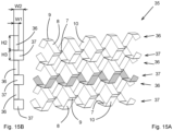
- Figures 15A and 15B show respectively a perspective view and a cross section of a part of a grate 35 according to the invention.
- the grate 35 comprises alternating structural elements 36, 37.
- the structural element 36 spirals clockwise, whilst the structural elements 37 spirals counter clockwise.
- the structural elements 36, 37 are connected to each other in the same way as shown in figure 11 .
- the structural element 36 has a rectangular cross section.
- the structural element 37 has a square cross section.
- the structural elements 36, 37 differ from each other in that the height H2 of the structural element 36 is larger than the height H3 of the structural element 37.
- the width W1 of structural element 36 is smaller than the width W2 of the structural element 37.
- the angles A of the structural elements 36, 37 are identical. To be able to connect the parts 7, 9 of the structural elements 32, 33 to each other the perimeter of structural element 36 being 2 ⁇ W1+2 ⁇ H2 is identical to the perimeter of structural element 27 being 2 ⁇ W2+2 ⁇ H3.
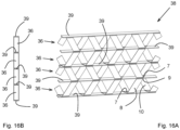
- Figures 16A and 16B show respectively a perspective view and a cross section of a part of a grate 38 according to the invention.
- the grate 38 comprises only structural elements 36, alternating spiraling in clockwise and counter clockwise direction.
- the grate 38 comprises flat strips 39 located between each pair of two structural elements 36, whereby the parts 7, 9 of the structural elements 36 are connected to the strip 39.
- the strip 39 has the same width W as the structural elements 36. This embodiment has the advantage that each structural element 36 can be positioned at any desired orientation with respect to a lower and upper structural element 36.
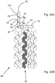
- Figures 17A and 17B show respectively a perspective view and a cross section of a part of a grate 40 according to the invention.
- the grate 40 comprises alternating structural elements 41, 42.
- the structural element 41 has a triangular cross section like structural element 18.
- the structural element 42 has a trapezium shaped cross section like structural element 16.
- the angle E between parts 7,10; 9,10 of the structural element 42 are identical to the angle D of the structural element 41, so 60 degrees.
- parts 7,9 of the structural elements 41, 42 can be connected to each other, whereby a grate 40 extending along a plane is obtained.
- parts 22 of the structural elements 41 and parts 8 of the structural elements 42 are aligned. However, it is also possible that these parts 8, 22 are mounted with an off set with respect to each other.
- Figures 18A and 18B show respectively a perspective view of a structural element 44 and a top view of an unfolded strip 45 of the structural element 44 according to the invention.
- the unfolded strip 45 comprises on the right side a number of fold lines 46 inclined under an angle A1 with respect to the longitudinal axis of the strip 45 and on the left side a number of fold lines 47 inclined under an angle A2 with respect to the longitudinal axis of the strip 45.
- the angle A2 is equal to angle A1 but the fold lines 46, 47 extend in opposite directions.
- the portion of the strip 45 comprises the fold lines 46 will be folded to obtain a coil spiralling in a counter clockwise direction, whilst the portion of the strip 45 comprises the fold lines 47 will be folded to obtain a coil spiralling in a clockwise direction.
- a part 48 is located bounded by two fold lines 49 extending perpendicular to the longitudinal axis of the strip 45. Connected to the part 48 at the fold line 49 is part 50 being connected to the right portion of the strip 45 by fold line 46. In the same manner connected to the part 48 at the other fold line 49 is part 51 being connected to the left portion of the strip 45 by fold line 47.
- the parts 48, 50, 51 forms connecting parts connecting the upper coil formed out of the right portion of the strip 45 and the lower coil formed out of the left portion of the strip 45.
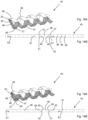
- Figures 19A and 19B show respectively a perspective view of a structural element 54 and a top view of an unfolded strip 55 of the structural element 54 according to the invention.
- the unfolded strip 55 comprises on the left side a number of fold lines 46 inclined under an angle A1 with respect to the longitudinal axis of the strip 55 and on the right side a number of fold lines 47 inclined under an angle A2 with respect to the longitudinal axis of the strip 55.
- the angle A2 is equal to angle A1 but the fold lines 46, 47 extend in opposite directions.
- the portion of the strip 55 comprises the fold lines 46 will be folded to obtain a coil spiralling in a counter clockwise direction, whilst the portion of the strip 55 comprises the fold lines 47 will be folded to obtain a coil spiralling in a clockwise direction.
- a part 48 is located bounded by two fold lines 49 extending in the same direction as the nearest fold line 46, 47..
- part 50 Connected to the part 48 at the fold line 49 is part 50 being connected to the left portion of the strip 55 by a further fold line 49.
- part 51 being connected to the right portion of the strip 45 by a further fold line 49.
- the parts 48, 50, 51 forms connecting parts connecting the upper coil formed out of the left portion of the strip 55 and the lower coil formed out of the right portion of the strip 55.
- Figures 20A and 20B show respectively a perspective view of a structural element 64 and a top view of an unfolded strip 65 of the structural element 44 according to the invention.
- the unfolded strip 65 comprises on the left side a number of fold lines 46 inclined under an angle A1 with respect to the longitudinal axis of the strip 65 and on the right side a number of fold lines 47 inclined under an angle A2 with respect to the longitudinal axis of the strip 65.
- the angle A2 is equal to angle A1.
- the portion of the strip 65 comprises the fold lines 46 will be folded to obtain a coil spiralling in a counter clockwise direction.
- the portion of the strip 65 comprises the fold lines 47 will be folded to obtain a coil spiralling in a counter clockwise direction.
- a part 48 is located bounded by two parallel fold lines 49 extending under an angle A3.
- part 50 Connected to the part 48 at the fold line 49 is part 50 being connected to the left portion of the strip 55 by fold line 46.
- part 51 being connected to the right portion of the strip 45 by fold line 47.
- the parts 48, 50, 51 forms connecting parts connecting the upper coil formed out of the left portion of the strip 65 and the lower coil formed out of the right portion of the strip 65.
- the strips 45, 55, 65 can be as long as desired and comprises as many transitions comprising connecting parts from one coil to another coil so that a single structural element 44, 54, 64 of any desired length determined by the length of each coil and any desired height determined by the height and number of coils can by manufactured without the need to position separate structural elements with respect to each other.
- the coils need only to be aligned with respect to each other.
- Each coils made from strip 45, 55, 65 can have any desired cross section, and height and width.
- FIGs 21A and 21B show respectively a perspective view and schematic top view of a part of a grate 74 according to the invention.
- the grate 94 comprises a number of similar coils 75, 75', 75", 75′′′ connected to each other.
- the coils 75', 75′′′ spiral in opposite direction to the coils 75, 75".
- coil 75' located in the left lower corner is connected with a portion of parts 77 to parts 76 of a coil 75" located on the right thereof.
- the coil 75' is connected with parts 76 to parts 78 of a coil 75′′′ located above it.
- grate 74 comprises further as many coils 75 in line with coil 75" and as many coils 75 in line with coil 75′′′ as desired.
- the corner forms a right angle.
- Figures 22A and 22B show respectively a perspective view and schematic top view of a part of a grate 84 according to the invention.
- the grate 84 comprises a number of similar coils 75, 75', 75", 75′′′ connected to each other.
- the coils 75', 75′′′ spiral in opposite direction to the coils 75, 75".
- the grate 84 also comprises two coils 85, 86.
- the coils 85 and 86 are a mirror image of each other.
- the coil 85 is connected with parts 76 to parts 78 of a coil 75.
- the coil 86 is connected with parts 76 to parts 78 of a coil 75.
- the coils 85, 86 are connected to each other at parts 87, 88 respectively, which parts 87, 88 extend under an angle of 45 degrees with the parts 76, 78. In this manner a corner has been created in the grate 84, which grate 84 comprises further as many coils 75 in line with the coils 75 connected to the coils 85, 86 as desired.
- the corner forms a right angle.
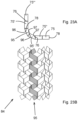
- FIGS 23A and 23B show respectively a perspective view and schematic top view of a part of a grate 94 according to the invention.
- the grate 94 comprises a number of similar coils 75, 75', 75", 75′′′ connected to each other.
- the coils 75', 75′′′ spiral in opposite direction to the coils 75, 75".
- the grate 94 also comprises two coils 95, 95' having a trapezium shaped cross section. The sharp corners in the trapezium shaped cross section is 67,5 degrees
- the coil 95 is connected with parts 96 to parts 78 of a coil 75.
- the coil 95' is connected with parts 97 to parts 76 of a coil 75.
- the coils 95, 95' are connected to each other at parts 97, 96 respectively. In this manner a corner can be created in the grate 94, which grate 94 comprises further as many coils 75 in line with the coils 75 connected to the coils 95, 95' as desired.
- the corner forms a rounded angle.
- Figures 24A and 24B show respectively a perspective view and schematic top view of a part of a grate 104 according to the invention.
- the grate 104 comprises a number of coils 75 as well as four coils 105, 105', 105", 105′′′ each having a trapezium shaped cross section. A coil spiralling in one direction is located between two other coils spiralling in another direction. The sharp corners in the trapezium shaped cross section is 78,75 degrees.
- the coil 105 is connected with parts 106 to parts 78 of a coil 75.
- the coil 105' is connected with parts 106 to parts 107 of a coil 105.
- the coil 105" is connected with parts 106 to parts 107 of a coil 105'.
- the coil 105′′′ is connected with parts 106 to parts 107 of a coil 105".
- the coil 105′′′ is connected with parts 107 to parts 76 of coil 76.
- grate 104 which grate 104 comprises further as many coils 75 in line with the coils 75 connected to the coils 105, 105′′′ as desired.
- the corner forms a rounded angle.
- the corner of grate 104 is more rounded as the corner of grate 94.
- Figure 25 shows a perspective view of a grate element 114 according to the invention, which grate 114 extend around an object like an air conditioner 115 mounted on top of a roof or against a wall.
- the grate 114 comprises a large number of coils having their axial direction extending in vertical direction. The coils are located in three planes, two planes being parallel to the sides of the box shaped air conditioner 115 and one plane located parallel to a front side of the air conditioner 115. The planes are connected to each other by corners as shown in the figures 24A-24B , for example.
- the grate 114 is provided with brackets 116 to be able to connect the grate 114 to a wall against which the air conditioner 115 is mounted.
- Figures 26A is a perspective view of another embodiment of a structural element 120 according to the invention.
- Figure 26B is a top view of an unfolded strip 121 of the structural element 16.
- Figure 26C is a cross section of the coil of the structural element 120.
- the coil of the structural element 120 comprises five different parts 122, 123, 124, 125, 126 connected to each other at folding lines 127, 128, 129, 130, 131.
- Each part 122, 123, 124, 125, 126 has a different width W.
- the coil of the structural element according to the invention can have as many flat parts as desired.
- the number of parts will normally be less than 10, preferably less than 5 and normally be 3 or 4.
- the grate according to the invention can be used a fence, separation wall, wall panel etc.
- the grates are made of steel or aluminium.
- the width B of the strip is preferably between 10 and 60 millimetre.
- the thickness T of the strip is preferably between 1 and 3 millimetre.
- the angle A is preferably between 30 and 150 degrees.
- the width W of the coil is preferably between 20 and 100 millimetre.
- the height H of the coil is preferably between 40 and 200 millimetre.
- the angle C is preferably between 60 and 170 degrees
Landscapes
- Engineering & Computer Science (AREA)
- Architecture (AREA)
- Civil Engineering (AREA)
- Structural Engineering (AREA)
- Coils Or Transformers For Communication (AREA)
- Coils Of Transformers For General Uses (AREA)
Applications Claiming Priority (1)
| Application Number | Priority Date | Filing Date | Title |
|---|---|---|---|
| NL2025847A NL2025847B1 (en) | 2020-06-17 | 2020-06-17 | A grate comprising at least one structural element |
Publications (3)
| Publication Number | Publication Date |
|---|---|
| EP3929370A1 EP3929370A1 (en) | 2021-12-29 |
| EP3929370C0 EP3929370C0 (en) | 2023-07-12 |
| EP3929370B1 true EP3929370B1 (en) | 2023-07-12 |
Family
ID=71895151
Family Applications (1)
| Application Number | Title | Priority Date | Filing Date |
|---|---|---|---|
| EP21178821.1A Active EP3929370B1 (en) | 2020-06-17 | 2021-06-10 | Grate comprising structural element |
Country Status (3)
| Country | Link |
|---|---|
| EP (1) | EP3929370B1 (pl) |
| NL (1) | NL2025847B1 (pl) |
| PL (1) | PL3929370T3 (pl) |
Family Cites Families (5)
| Publication number | Priority date | Publication date | Assignee | Title |
|---|---|---|---|---|
| US339732A (en) * | 1886-04-13 | Fence-rail | ||
| US2978077A (en) * | 1958-12-09 | 1961-04-04 | Hill Cross Company Inc | Three-dimensional structure and elements thereof |
| US4291515A (en) * | 1978-11-07 | 1981-09-29 | John Lysaght International Holdings S.A. | Structural elements |
| US4491003A (en) * | 1981-06-23 | 1985-01-01 | Maryland Wire Belts, Inc. | Fabrication of helically-wound spirals for metal wire belts |
| SE461075B (sv) * | 1987-11-25 | 1990-01-08 | Skanska Ab | Element foer uppbyggnad av fackverksliv till balkar och foerfarande foer tillverkning av ett saadant element samt balkliv uppbyggt av tvaa eller flera saadana element |
-
2020
- 2020-06-17 NL NL2025847A patent/NL2025847B1/en active
-
2021
- 2021-06-10 EP EP21178821.1A patent/EP3929370B1/en active Active
- 2021-06-10 PL PL21178821.1T patent/PL3929370T3/pl unknown
Also Published As
| Publication number | Publication date |
|---|---|
| EP3929370C0 (en) | 2023-07-12 |
| NL2025847B1 (en) | 2022-02-22 |
| EP3929370A1 (en) | 2021-12-29 |
| PL3929370T3 (pl) | 2023-12-04 |
Similar Documents
| Publication | Publication Date | Title |
|---|---|---|
| EP0443408B1 (en) | Reversibly expandable structures | |
| US6047513A (en) | Steel construction system | |
| US5660119A (en) | Lightweight structural beam | |
| US6067764A (en) | Insulation assembly including a spacing element | |
| EP0491277B1 (en) | A honeycomb member and a honeycomb | |
| AU2006313679B2 (en) | Method for manufacturing of cellular board, cellular board, method for producing cellular board element of steel plate strip, and production line | |
| US7134250B2 (en) | Building panels | |
| CN101605951A (zh) | 单条单腹板的格栅t型件 | |
| US6186393B1 (en) | Carton box made out of several blanks | |
| US11319133B2 (en) | Multi-laminate folded materials for construction of boxes and other objects | |
| US4291515A (en) | Structural elements | |
| EP0852644A1 (en) | Beam | |
| EP3929370B1 (en) | Grate comprising structural element | |
| CN101194075B (zh) | 建筑物墙板和建筑物结构 | |
| EP0882857B1 (en) | Furring strips for fence and fence | |
| CN1180171C (zh) | 建筑板材 | |
| WO1993003233A1 (en) | Construction according to a double-curved surface | |
| CN1131362C (zh) | 预制屋面板件及其承重梁 | |
| EP3827143B1 (en) | Modular building construction | |
| EP0673461B1 (en) | Wall form | |
| CN1201858A (zh) | 钢建筑用的构架件与构架联接系统 | |
| EP1286002A2 (en) | Shutters | |
| JP3455713B2 (ja) | トラス筋 | |
| SU1048075A1 (ru) | Слоиста панель | |
| WO2003087486A1 (en) | Roof structure |
Legal Events
| Date | Code | Title | Description |
|---|---|---|---|
| PUAI | Public reference made under article 153(3) epc to a published international application that has entered the european phase |
Free format text: ORIGINAL CODE: 0009012 |
|
| STAA | Information on the status of an ep patent application or granted ep patent |
Free format text: STATUS: THE APPLICATION HAS BEEN PUBLISHED |
|
| AK | Designated contracting states |
Kind code of ref document: A1 Designated state(s): AL AT BE BG CH CY CZ DE DK EE ES FI FR GB GR HR HU IE IS IT LI LT LU LV MC MK MT NL NO PL PT RO RS SE SI SK SM TR |
|
| B565 | Issuance of search results under rule 164(2) epc |
Effective date: 20211129 |
|
| STAA | Information on the status of an ep patent application or granted ep patent |
Free format text: STATUS: REQUEST FOR EXAMINATION WAS MADE |
|
| 17P | Request for examination filed |
Effective date: 20220616 |
|
| RBV | Designated contracting states (corrected) |
Designated state(s): AL AT BE BG CH CY CZ DE DK EE ES FI FR GB GR HR HU IE IS IT LI LT LU LV MC MK MT NL NO PL PT RO RS SE SI SK SM TR |
|
| GRAP | Despatch of communication of intention to grant a patent |
Free format text: ORIGINAL CODE: EPIDOSNIGR1 |
|
| STAA | Information on the status of an ep patent application or granted ep patent |
Free format text: STATUS: GRANT OF PATENT IS INTENDED |
|
| INTG | Intention to grant announced |
Effective date: 20230221 |
|
| GRAS | Grant fee paid |
Free format text: ORIGINAL CODE: EPIDOSNIGR3 |
|
| GRAA | (expected) grant |
Free format text: ORIGINAL CODE: 0009210 |
|
| STAA | Information on the status of an ep patent application or granted ep patent |
Free format text: STATUS: THE PATENT HAS BEEN GRANTED |
|
| AK | Designated contracting states |
Kind code of ref document: B1 Designated state(s): AL AT BE BG CH CY CZ DE DK EE ES FI FR GB GR HR HU IE IS IT LI LT LU LV MC MK MT NL NO PL PT RO RS SE SI SK SM TR |
|
| REG | Reference to a national code |
Ref country code: CH Ref legal event code: EP |
|
| REG | Reference to a national code |
Ref country code: IE Ref legal event code: FG4D |
|
| REG | Reference to a national code |
Ref country code: DE Ref legal event code: R096 Ref document number: 602021003374 Country of ref document: DE |
|
| U01 | Request for unitary effect filed |
Effective date: 20230802 |
|
| U07 | Unitary effect registered |
Designated state(s): AT BE BG DE DK EE FI FR IT LT LU LV MT NL PT SE SI Effective date: 20230810 |
|
| REG | Reference to a national code |
Ref country code: LT Ref legal event code: MG9D |
|
| PG25 | Lapsed in a contracting state [announced via postgrant information from national office to epo] |
Ref country code: GR Free format text: LAPSE BECAUSE OF FAILURE TO SUBMIT A TRANSLATION OF THE DESCRIPTION OR TO PAY THE FEE WITHIN THE PRESCRIBED TIME-LIMIT Effective date: 20231013 |
|
| PG25 | Lapsed in a contracting state [announced via postgrant information from national office to epo] |
Ref country code: ES Free format text: LAPSE BECAUSE OF FAILURE TO SUBMIT A TRANSLATION OF THE DESCRIPTION OR TO PAY THE FEE WITHIN THE PRESCRIBED TIME-LIMIT Effective date: 20230712 |
|
| PG25 | Lapsed in a contracting state [announced via postgrant information from national office to epo] |
Ref country code: IS Free format text: LAPSE BECAUSE OF FAILURE TO SUBMIT A TRANSLATION OF THE DESCRIPTION OR TO PAY THE FEE WITHIN THE PRESCRIBED TIME-LIMIT Effective date: 20231112 |
|
| PG25 | Lapsed in a contracting state [announced via postgrant information from national office to epo] |
Ref country code: RS Free format text: LAPSE BECAUSE OF FAILURE TO SUBMIT A TRANSLATION OF THE DESCRIPTION OR TO PAY THE FEE WITHIN THE PRESCRIBED TIME-LIMIT Effective date: 20230712 Ref country code: NO Free format text: LAPSE BECAUSE OF FAILURE TO SUBMIT A TRANSLATION OF THE DESCRIPTION OR TO PAY THE FEE WITHIN THE PRESCRIBED TIME-LIMIT Effective date: 20231012 Ref country code: IS Free format text: LAPSE BECAUSE OF FAILURE TO SUBMIT A TRANSLATION OF THE DESCRIPTION OR TO PAY THE FEE WITHIN THE PRESCRIBED TIME-LIMIT Effective date: 20231112 Ref country code: HR Free format text: LAPSE BECAUSE OF FAILURE TO SUBMIT A TRANSLATION OF THE DESCRIPTION OR TO PAY THE FEE WITHIN THE PRESCRIBED TIME-LIMIT Effective date: 20230712 Ref country code: GR Free format text: LAPSE BECAUSE OF FAILURE TO SUBMIT A TRANSLATION OF THE DESCRIPTION OR TO PAY THE FEE WITHIN THE PRESCRIBED TIME-LIMIT Effective date: 20231013 Ref country code: ES Free format text: LAPSE BECAUSE OF FAILURE TO SUBMIT A TRANSLATION OF THE DESCRIPTION OR TO PAY THE FEE WITHIN THE PRESCRIBED TIME-LIMIT Effective date: 20230712 |
|
| REG | Reference to a national code |
Ref country code: DE Ref legal event code: R097 Ref document number: 602021003374 Country of ref document: DE |
|
| PG25 | Lapsed in a contracting state [announced via postgrant information from national office to epo] |
Ref country code: SM Free format text: LAPSE BECAUSE OF FAILURE TO SUBMIT A TRANSLATION OF THE DESCRIPTION OR TO PAY THE FEE WITHIN THE PRESCRIBED TIME-LIMIT Effective date: 20230712 Ref country code: RO Free format text: LAPSE BECAUSE OF FAILURE TO SUBMIT A TRANSLATION OF THE DESCRIPTION OR TO PAY THE FEE WITHIN THE PRESCRIBED TIME-LIMIT Effective date: 20230712 Ref country code: CZ Free format text: LAPSE BECAUSE OF FAILURE TO SUBMIT A TRANSLATION OF THE DESCRIPTION OR TO PAY THE FEE WITHIN THE PRESCRIBED TIME-LIMIT Effective date: 20230712 Ref country code: SK Free format text: LAPSE BECAUSE OF FAILURE TO SUBMIT A TRANSLATION OF THE DESCRIPTION OR TO PAY THE FEE WITHIN THE PRESCRIBED TIME-LIMIT Effective date: 20230712 |
|
| PLBE | No opposition filed within time limit |
Free format text: ORIGINAL CODE: 0009261 |
|
| STAA | Information on the status of an ep patent application or granted ep patent |
Free format text: STATUS: NO OPPOSITION FILED WITHIN TIME LIMIT |
|
| 26N | No opposition filed |
Effective date: 20240415 |
|
| U20 | Renewal fee for the european patent with unitary effect paid |
Year of fee payment: 4 Effective date: 20240627 |
|
| PG25 | Lapsed in a contracting state [announced via postgrant information from national office to epo] |
Ref country code: MC Free format text: LAPSE BECAUSE OF FAILURE TO SUBMIT A TRANSLATION OF THE DESCRIPTION OR TO PAY THE FEE WITHIN THE PRESCRIBED TIME-LIMIT Effective date: 20230712 |
|
| PG25 | Lapsed in a contracting state [announced via postgrant information from national office to epo] |
Ref country code: IE Free format text: LAPSE BECAUSE OF NON-PAYMENT OF DUE FEES Effective date: 20240610 |
|
| U20 | Renewal fee for the european patent with unitary effect paid |
Year of fee payment: 5 Effective date: 20250519 |
|
| PGFP | Annual fee paid to national office [announced via postgrant information from national office to epo] |
Ref country code: PL Payment date: 20250602 Year of fee payment: 5 |
|
| PGFP | Annual fee paid to national office [announced via postgrant information from national office to epo] |
Ref country code: GB Payment date: 20250618 Year of fee payment: 5 |
|
| PGFP | Annual fee paid to national office [announced via postgrant information from national office to epo] |
Ref country code: CH Payment date: 20250701 Year of fee payment: 5 |
|
| PG25 | Lapsed in a contracting state [announced via postgrant information from national office to epo] |
Ref country code: CY Free format text: LAPSE BECAUSE OF FAILURE TO SUBMIT A TRANSLATION OF THE DESCRIPTION OR TO PAY THE FEE WITHIN THE PRESCRIBED TIME-LIMIT; INVALID AB INITIO Effective date: 20210610 |