EP3929126A1 - Method of replacing a battery and an elevator system - Google Patents
Method of replacing a battery and an elevator system Download PDFInfo
- Publication number
- EP3929126A1 EP3929126A1 EP20182406.7A EP20182406A EP3929126A1 EP 3929126 A1 EP3929126 A1 EP 3929126A1 EP 20182406 A EP20182406 A EP 20182406A EP 3929126 A1 EP3929126 A1 EP 3929126A1
- Authority
- EP
- European Patent Office
- Prior art keywords
- battery
- elevator system
- discharging
- elevator
- discharge request
- Prior art date
- Legal status (The legal status is an assumption and is not a legal conclusion. Google has not performed a legal analysis and makes no representation as to the accuracy of the status listed.)
- Granted
Links
Images

Classifications
-
- B—PERFORMING OPERATIONS; TRANSPORTING
- B66—HOISTING; LIFTING; HAULING
- B66B—ELEVATORS; ESCALATORS OR MOVING WALKWAYS
- B66B5/00—Applications of checking, fault-correcting, or safety devices in elevators
- B66B5/0087—Devices facilitating maintenance, repair or inspection tasks
-
- B—PERFORMING OPERATIONS; TRANSPORTING
- B66—HOISTING; LIFTING; HAULING
- B66B—ELEVATORS; ESCALATORS OR MOVING WALKWAYS
- B66B7/00—Other common features of elevators
-
- B—PERFORMING OPERATIONS; TRANSPORTING
- B66—HOISTING; LIFTING; HAULING
- B66B—ELEVATORS; ESCALATORS OR MOVING WALKWAYS
- B66B1/00—Control systems of elevators in general
- B66B1/34—Details, e.g. call counting devices, data transmission from car to control system, devices giving information to the control system
- B66B1/46—Adaptations of switches or switchgear
- B66B1/461—Adaptations of switches or switchgear characterised by their shape or profile
- B66B1/466—Adaptations of switches or switchgear characterised by their shape or profile facilitating maintenance, installation, removal, replacement or repair
-
- B—PERFORMING OPERATIONS; TRANSPORTING
- B66—HOISTING; LIFTING; HAULING
- B66B—ELEVATORS; ESCALATORS OR MOVING WALKWAYS
- B66B19/00—Mining-hoist operation
- B66B19/007—Mining-hoist operation method for modernisation of elevators
Definitions
- This invention relates to a solution for improving the safety of maintenance of an elevator system comprising a battery.
- Known elevator systems contain one or more batteries associated with different elevator functions.
- One or more batteries may be included in the power supply devices as backup for breaks in the electric supply, for instance.
- the emergency lighting and emergency communication from the elevator car may be provided with one or more batteries.
- An object of the present invention is to solve the above-mentioned drawback and to provide a solution which improves the safety in an elevator system where one or more batteries are utilized. This object is achieved with the solution defined in the independent method claim 1 and with the elevator system as defined in the independent claim 12.
- the risk of injuries to personnel or to equipment can be minimized when the elevator system is arranged to discharge energy from the battery, in particular from a high-energy battery, in response to a discharge request. In this way, once service personnel start maintenance work involving the battery, the maintenance work can be done under more safe conditions than previously.
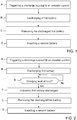
- Figure 1 illustrates a first embodiment of a method of replacing a battery in an elevator system, which may be implemented in the elevator system 1 illustrated in Figure 3 , for instance.
- the elevator system 1 is provided with power supply devices 2 connected to an electric network 3 for supplying power to operational devices 4, 10, 17, 19 of the elevator system.
- the power supply devices 2 include a drive, such as a frequency converter, supplying electricity to the electrical motor 4 of a hoisting machinery 17 which moves an elevator car 5 and a counterweight 6 in an elevator shaft 7.
- the power supply devices 2 may be located in several different locations. In Figure 3 it is by way of example assumed that the power supply devices 2 are located in an elevator control 8 controlling the operation of the elevator system 1.
- the elevator control 8 may be located in a control cabinet in a machine room, for instance.
- the elevator control may be disposed in a landing at one of the floors of the building, for instance. In that case the elevator control may be located next to a landing door, for instance.
- the elevator control may be located in shaft 7, close to the hoisting machinery 17.
- the elevator system 1 illustrated in Figure 1 is provided with one or more batteries 9.
- two batteries 9 are illustrated by way of example.
- One battery is included in the power supply devices 2, such as in connection with the drive.
- the battery 9 can operate as a backup power supply during power outage of the mains from the electric network 3.
- the elevator car 5 With power supplied from this elevator drive battery, the elevator car 5 may be relocated to a landing to release elevator passengers.
- the battery 9 can also be a backup power supply for one or more hoisting machinery 17 brakes.
- the elevator car 5 has a backup power supply in the form of a battery 9 to secure operation of selected functions, such as emergency lighting 10 and an emergency communication device 20. Irrespectively of the number or locations of the batteries 9, these batteries are charged by a monitoring unit 11 including a battery charger and a switch, which is included in the power supply devices 2 in the illustrated example.
- the battery replacement method of Figure 1 is initiated in step A by triggering a discharge request to the elevator control 8. This discharge request may be triggered in several alternative ways, as illustrated in Figure 3 .
- the elevator control 8 may be provided with a manual input 12 which is used to trigger the discharge request.
- the manual input 12 may be a keyboard with buttons, or alternative as a connector socket to which a maintenance person may connect a counterpart socked of a portable keyboard. In any case, by pressing a correct button or button combination, the discharging request may be triggered to the elevator control 8.
- a second alternative is that the maintenance person is provided with a mobile communication device 13 which transmits the discharging request wirelessly directly to the elevator control 8, or alternatively, wirelessly to a communication system 14, which forwards the discharging request wirelessly or via a wired connection to the elevator control 8.
- a third alternative is that the discharging request is triggered remotely at a remote service center 15 or in a cloud, from where the discharge request is forwarded via a communication system 14 to the elevator control 8.
- Maintenance module refers to a service module containing service operations. Such a module 16 may be implemented by software only or by a combination of software and hardware, for instance. Maintenance modules will be scheduled in advance in a service center or in a cloud. Each maintenance module contains selected maintenance operations to be performed in elevator site by service personnel. When a maintenance module includes battery replacing operation, discharge request may be triggered such that the battery will be discharged shortly before the maintenance personnel arrives to the site of the elevator system. Alternatively, the service person may access a user interface to schedule a date and time when maintenance is planned, in which case elevator control 8 may trigger the discharge request at the scheduled time.
- discharging of the first battery 9, which refers to a battery currently used in the elevator system 1, is initiated in step B of Figure 1 .
- the used discharging alternative may be fixed, in such a way that the same discharging alternative is always used.
- the discharge load is selected separately by the elevator control or maintenance personnel each time discharging is needed. In that case the elevator status may determine the most appropriate discharging alternative for that specific moment.
- a first alternative is that the discharging is carried out by connecting the battery 9 to an operational device of the elevator system which during operation of the elevator system consumes the charged energy from the battery 9.
- operational devices include a line filter of the drive which is included in the power supply devices 2, lighting devices 10 in the elevator car the electric motor 4 of the hoisting machinery 17 and a braking resistor 19.
- a second alternative is that the elevator system is provided with a dedicated discharging equipment 18 and that the battery is discharged by connecting it to this discharging equipment.
- a discharging equipment may include a resistor which consumes the energy charged in the battery 9 and dissipates it as heat to surroundings, for instance.
- a third alternative is that the discharging is done to the mains network, in other words to the electric network 3.
- the monitoring unit 11 may be provided with a battery charger and also with a switch controlling the charging and discharging under control of the elevator control 8.
- the elevator control 8 interrupts charging of the first battery 9 and discharges the first battery 9 by changing a state of the switch of the monitoring unit 11 such that the first battery 9 is disconnected from the power supply devices 2 and connected to one of the operational devices of the elevator system 1 or to the dedicated discharging equipment 18 which consumes energy from the battery.
- the first battery 9 can be removed from the elevator system 1 in step C of Figure 1 .
- a second new battery may be installed in the elevator system 1 as a replacement to the removed first battery.
- Figure 2 illustrates a second method of replacing a battery in an elevator system, which also may be implemented in the elevator system 1 illustrated in Figure 3 , for instance.
- the embodiment of Figure 2 is very similar to the one explained in connection with Figure 1 . Therefore, in the following, the embodiment of Figure 2 will be mainly explained by pointing out the differences as compared to the embodiment of Figure 1 .
- an additional method step E is included where it is checked whether or not the charging level of the first battery has reached a predetermined level. Consequently, discharging of the first battery 9 continues until the charging of the first battery reaches a predetermined level or limit.
- the monitoring unit 11 monitors the state of the first battery and interrupts the discharging when the charging level reaches the predetermined level.
- the predetermined level at which discharging should be interrupted varies depending on the battery type. Typically discharging should be interrupted when the charging level reaches 50% to 30% of the full charge. In case of a high energy density battery such as a Li-Ion battery, discharging should be interrupted when the battery has a charging level SoC (State of Charge) mentioned in the United Nations Recommendations on the Transport of Dangerous Goods UN3480 or UN3481. The current version for year 2020 of UN3480 and UN3481 mention a current SoC limit of 30%, though this limit may change in later versions of these regulations. Consequently, charging of such a battery may be interrupted at 30% of the full charge, for instance. Alternatively or additionally, elevator control may be configured such that the discharge level is adjustable and can be changed manually and / or remotely.
- SoC State of Charge
- an additional method step F is included.
- the maintenance person after triggering discharging of the first battery 9, remains waiting for an indication verifying that the battery has actually been discharged.
- Such an indication may be provided by the elevator control 8 via the manual input 12, for instance, once the monitoring unit 11 has determined that the first battery has been discharged to a correct level.
Landscapes
- Maintenance And Inspection Apparatuses For Elevators (AREA)
- Elevator Control (AREA)
- Indicating And Signalling Devices For Elevators (AREA)
Abstract
Description
- This invention relates to a solution for improving the safety of maintenance of an elevator system comprising a battery.
- Known elevator systems contain one or more batteries associated with different elevator functions. One or more batteries may be included in the power supply devices as backup for breaks in the electric supply, for instance. Also, the emergency lighting and emergency communication from the elevator car may be provided with one or more batteries.
- Battery technologies have developed significantly in recent years. Due to this the energy density of batteries has increased on relatively high levels. This has caused a need for new solutions in order to be able to safely handle batteries during maintenance.
- Traditionally, lead acid batteries and sealed acid batteries have been used in elevator systems. Due to their battery chemistry, only low amount of battery supervision was required. Therefore, with the new batteries having high energy density and different failure modes, new practices, including new maintenance and installation operations, will be developed to ensure elevator safety.
- An object of the present invention is to solve the above-mentioned drawback and to provide a solution which improves the safety in an elevator system where one or more batteries are utilized. This object is achieved with the solution defined in the
independent method claim 1 and with the elevator system as defined in theindependent claim 12. - The risk of injuries to personnel or to equipment can be minimized when the elevator system is arranged to discharge energy from the battery, in particular from a high-energy battery, in response to a discharge request. In this way, once service personnel start maintenance work involving the battery, the maintenance work can be done under more safe conditions than previously.
- Preferred embodiments of the invention are disclosed in the dependent claims.
- In the following the present invention will be described in closer detail by way of example and with reference to the attached drawings, in which
-
Figure 1 is a flow diagram of a first embodiment of a method, -
Figure 2 is a flow diagram of a second embodiment of a method, and -
Figure 3 illustrates an elevator system. -
Figure 1 illustrates a first embodiment of a method of replacing a battery in an elevator system, which may be implemented in theelevator system 1 illustrated inFigure 3 , for instance. - The
elevator system 1 is provided withpower supply devices 2 connected to anelectric network 3 for supplying power tooperational devices Figure 3 it is by way of example assumed that thepower supply devices 2 include a drive, such as a frequency converter, supplying electricity to theelectrical motor 4 of ahoisting machinery 17 which moves anelevator car 5 and acounterweight 6 in anelevator shaft 7. - The
power supply devices 2 may be located in several different locations. InFigure 3 it is by way of example assumed that thepower supply devices 2 are located in anelevator control 8 controlling the operation of theelevator system 1. Theelevator control 8 may be located in a control cabinet in a machine room, for instance. Alternatively, in case of an elevator system without a machine room, the elevator control may be disposed in a landing at one of the floors of the building, for instance. In that case the elevator control may be located next to a landing door, for instance. Alternatively or additionally, the elevator control may be located inshaft 7, close to thehoisting machinery 17. - The
elevator system 1 illustrated inFigure 1 is provided with one ormore batteries 9. In the illustrated example twobatteries 9 are illustrated by way of example. One battery is included in thepower supply devices 2, such as in connection with the drive. At such a location thebattery 9 can operate as a backup power supply during power outage of the mains from theelectric network 3. With power supplied from this elevator drive battery, theelevator car 5 may be relocated to a landing to release elevator passengers. Thebattery 9 can also be a backup power supply for one ormore hoisting machinery 17 brakes. Further, in the example illustrated inFigure 3 theelevator car 5 has a backup power supply in the form of abattery 9 to secure operation of selected functions, such asemergency lighting 10 and anemergency communication device 20. Irrespectively of the number or locations of thebatteries 9, these batteries are charged by amonitoring unit 11 including a battery charger and a switch, which is included in thepower supply devices 2 in the illustrated example. - In particular when the battery or
batteries 9 are high energy density batteries, such as Li-Ion (Lithium-Ion) batteries, it is necessary to provide special attention to safety during maintenance work including handling and replacement of these batteries. To facilitate this, the battery replacement method ofFigure 1 is initiated in step A by triggering a discharge request to theelevator control 8. This discharge request may be triggered in several alternative ways, as illustrated inFigure 3 . - The
elevator control 8 may be provided with amanual input 12 which is used to trigger the discharge request. In that case themanual input 12 may be a keyboard with buttons, or alternative as a connector socket to which a maintenance person may connect a counterpart socked of a portable keyboard. In any case, by pressing a correct button or button combination, the discharging request may be triggered to theelevator control 8. - A second alternative is that the maintenance person is provided with a
mobile communication device 13 which transmits the discharging request wirelessly directly to theelevator control 8, or alternatively, wirelessly to acommunication system 14, which forwards the discharging request wirelessly or via a wired connection to theelevator control 8. - A third alternative is that the discharging request is triggered remotely at a
remote service center 15 or in a cloud, from where the discharge request is forwarded via acommunication system 14 to theelevator control 8. - It is also possible that the discharge request is triggered at the same time a maintenance module is performed. Maintenance module refers to a service module containing service operations. Such a
module 16 may be implemented by software only or by a combination of software and hardware, for instance. Maintenance modules will be scheduled in advance in a service center or in a cloud. Each maintenance module contains selected maintenance operations to be performed in elevator site by service personnel. When a maintenance module includes battery replacing operation, discharge request may be triggered such that the battery will be discharged shortly before the maintenance personnel arrives to the site of the elevator system. Alternatively, the service person may access a user interface to schedule a date and time when maintenance is planned, in whichcase elevator control 8 may trigger the discharge request at the scheduled time. - Once the discharge request has been triggered, discharging of the
first battery 9, which refers to a battery currently used in theelevator system 1, is initiated in step B ofFigure 1 . Several alternatives for discharging the first battery exists. In an elevator system the used discharging alternative may be fixed, in such a way that the same discharging alternative is always used. Alternatively, it is possible that the discharge load is selected separately by the elevator control or maintenance personnel each time discharging is needed. In that case the elevator status may determine the most appropriate discharging alternative for that specific moment. - A first alternative is that the discharging is carried out by connecting the
battery 9 to an operational device of the elevator system which during operation of the elevator system consumes the charged energy from thebattery 9. Examples of such operational devices include a line filter of the drive which is included in thepower supply devices 2,lighting devices 10 in the elevator car theelectric motor 4 of thehoisting machinery 17 and abraking resistor 19. - A second alternative is that the elevator system is provided with a dedicated discharging
equipment 18 and that the battery is discharged by connecting it to this discharging equipment. Such a discharging equipment may include a resistor which consumes the energy charged in thebattery 9 and dissipates it as heat to surroundings, for instance. - A third alternative is that the discharging is done to the mains network, in other words to the
electric network 3. InFigure 3 themonitoring unit 11 may be provided with a battery charger and also with a switch controlling the charging and discharging under control of theelevator control 8. In that case theelevator control 8 interrupts charging of thefirst battery 9 and discharges thefirst battery 9 by changing a state of the switch of themonitoring unit 11 such that thefirst battery 9 is disconnected from thepower supply devices 2 and connected to one of the operational devices of theelevator system 1 or to the dedicated dischargingequipment 18 which consumes energy from the battery. - Once the
first battery 9 is discharged, the first battery can be removed from theelevator system 1 in step C ofFigure 1 . Finally, a second new battery may be installed in theelevator system 1 as a replacement to the removed first battery. -
Figure 2 illustrates a second method of replacing a battery in an elevator system, which also may be implemented in theelevator system 1 illustrated inFigure 3 , for instance. The embodiment ofFigure 2 is very similar to the one explained in connection withFigure 1 . Therefore, in the following, the embodiment ofFigure 2 will be mainly explained by pointing out the differences as compared to the embodiment ofFigure 1 . - In
Figure 2 an additional method step E is included where it is checked whether or not the charging level of the first battery has reached a predetermined level. Consequently, discharging of thefirst battery 9 continues until the charging of the first battery reaches a predetermined level or limit. InFigure 3 themonitoring unit 11 monitors the state of the first battery and interrupts the discharging when the charging level reaches the predetermined level. - The predetermined level at which discharging should be interrupted varies depending on the battery type. Typically discharging should be interrupted when the charging level reaches 50% to 30% of the full charge. In case of a high energy density battery such as a Li-Ion battery, discharging should be interrupted when the battery has a charging level SoC (State of Charge) mentioned in the United Nations Recommendations on the Transport of Dangerous Goods UN3480 or UN3481. The current version for year 2020 of UN3480 and UN3481 mention a current SoC limit of 30%, though this limit may change in later versions of these regulations. Consequently, charging of such a battery may be interrupted at 30% of the full charge, for instance. Alternatively or additionally, elevator control may be configured such that the discharge level is adjustable and can be changed manually and / or remotely.
- Additionally, in
Figure 2 an additional method step F is included. At this stage the maintenance person, after triggering discharging of thefirst battery 9, remains waiting for an indication verifying that the battery has actually been discharged. Such an indication may be provided by theelevator control 8 via themanual input 12, for instance, once the monitoringunit 11 has determined that the first battery has been discharged to a correct level. - It is to be understood that the above description and the accompanying figures are only intended to illustrate the present invention. It will be obvious to a person skilled in the art that the invention can be varied and modified without departing from the scope of the invention.
Claims (16)
- A method of replacing a battery in an elevator system, characterized in that the method comprises:triggering (A) a discharge request to an elevator control (8),discharging (B) a first battery (9) in the elevator system in response to the discharge request,removing (C) the discharged first battery (9) from the elevator system,installing (D) a second battery as a replacement for the removed first battery.
- The method according to claim 1, wherein discharging (E) of the first battery (9) is continued until the charging level of the first battery reaches a predetermined level.
- The method according to claim 1 or 2, wherein discharging (E) of the first battery (9) is continued until the charging level of the first battery reaches a predetermined level which is less than 50% of full charge, preferably 30% or less of the full charge.
- The method according to one of claims 1 to 3, wherein the discharging is carried out by connecting the first battery (9) to an operational device of the elevator system (1) which during operation of the elevator system consumes the charged energy from the first battery (9).
- The method according to one of claims 1 to 4, wherein the discharging is carried out by connecting the first battery (9) for discharging to a line filter (2), to a hoisting machinery (17), to a braking resistor (19) or to a mains network.
- The method according to one of claims 1 to 3, wherein the discharging is carried out by connecting the first battery (9) to a dedicated discharging equipment (18).
- The method according to one of claims 1 to 6, wherein the discharge request is triggered from a manual input (12) of the elevator control (8).
- The method according to one of claims 1 to 6, wherein the discharge request is triggered by a mobile device (13) transmitting the discharge request via a wireless connection to the elevator control (8).
- The method according to one of claims 1 to 6, wherein the discharge request is triggered at a remote service center (15) which forwards the discharge request via a communication network (14) to the elevator control (8).
- The method according to one of claims 1 to 9, wherein the discharge request is triggered by a maintenance module of the elevator system.
- The method according to one of the previous claims, wherein
an indication (F) that the first battery (9) has been discharged is awaited after triggering the discharge request, and
the first battery is removed (C) after said indication. - An elevator system (1) comprising:power supply devices (2) providing operational devices (4, 10, 17, 19) of the elevator system (1) with power,an elevator control controlling (8) the operation of the elevator system (1), anda first battery (9) which is charged by the power supply devices (2), characterized in thatthe elevator control (8) is arranged to interrupt charging of the first battery (9) and to discharge the first battery (9) in response to a discharge request.
- The elevator system of claim 12, wherein
the elevator system (1) comprises a switch (11) controlling charging and discharging of the first battery (9) under control of the elevator control (8), and
the elevator control (8) interrupts charging of the first battery (9) and discharges the first battery (9) by changing a state of the switch (11) such that the first battery (9) is disconnected from the power supply devices (2) and connected for discharging to one of the operational devices (4, 10 17, 19) of the elevator system (1), to a dedicated discharging equipment (18) which consumes energy from the first battery (9) or to a mains network. - The elevator system of claim 12 or 13, wherein the elevator system (1) comprises a monitoring unit (11) monitoring the state of the first battery (9), and which comprises a switch interrupting discharging of the first battery (9) when the charging level of the first battery (9) reaches a predetermined level.
- The elevator system according to one of claims 12 to 14, wherein the elevator system comprises a monitoring unit (11) monitoring the state of the first battery (9) and the elevator control (8) provides an indication that the first battery (9) has been discharged when the charging level of the first battery (9) reaches a predetermined level.
- The elevator system according to one of claims 12 to 15, wherein the first battery (9) is one of a backup power supply of a hoisting motor, a backup power supply of one or more hoisting machinery (17) brakes, a backup power supply of an emergency communication device (20) or a power supply of emergency lighting (10).
Priority Applications (4)
| Application Number | Priority Date | Filing Date | Title |
|---|---|---|---|
| DK20182406.7T DK3929126T3 (en) | 2020-06-26 | 2020-06-26 | PROCEDURE FOR REPLACEMENT OF A BATTERY AND ELEVATOR SYSTEM |
| ES20182406T ES2944071T3 (en) | 2020-06-26 | 2020-06-26 | Replacing method of a battery and an elevator system |
| EP20182406.7A EP3929126B1 (en) | 2020-06-26 | 2020-06-26 | Method of replacing a battery and an elevator system |
| FIEP20182406.7T FI3929126T3 (en) | 2020-06-26 | 2020-06-26 | Method of replacing a battery and an elevator system |
Applications Claiming Priority (1)
| Application Number | Priority Date | Filing Date | Title |
|---|---|---|---|
| EP20182406.7A EP3929126B1 (en) | 2020-06-26 | 2020-06-26 | Method of replacing a battery and an elevator system |
Publications (2)
| Publication Number | Publication Date |
|---|---|
| EP3929126A1 true EP3929126A1 (en) | 2021-12-29 |
| EP3929126B1 EP3929126B1 (en) | 2023-02-15 |
Family
ID=71170368
Family Applications (1)
| Application Number | Title | Priority Date | Filing Date |
|---|---|---|---|
| EP20182406.7A Active EP3929126B1 (en) | 2020-06-26 | 2020-06-26 | Method of replacing a battery and an elevator system |
Country Status (4)
| Country | Link |
|---|---|
| EP (1) | EP3929126B1 (en) |
| DK (1) | DK3929126T3 (en) |
| ES (1) | ES2944071T3 (en) |
| FI (1) | FI3929126T3 (en) |
Cited By (1)
| Publication number | Priority date | Publication date | Assignee | Title |
|---|---|---|---|---|
| WO2024040263A1 (en) * | 2022-08-19 | 2024-02-22 | Safeworks, Llc | Battery-powered windfarm elevator system |
Citations (2)
| Publication number | Priority date | Publication date | Assignee | Title |
|---|---|---|---|---|
| US20020053490A1 (en) * | 2000-11-09 | 2002-05-09 | Hirokazu Banno | Apparatus for controlling elevator |
| US20170260026A1 (en) * | 2014-07-31 | 2017-09-14 | Franck Dominguez | Battery installed in elevator car |
-
2020
- 2020-06-26 ES ES20182406T patent/ES2944071T3/en active Active
- 2020-06-26 FI FIEP20182406.7T patent/FI3929126T3/en active
- 2020-06-26 EP EP20182406.7A patent/EP3929126B1/en active Active
- 2020-06-26 DK DK20182406.7T patent/DK3929126T3/en active
Patent Citations (2)
| Publication number | Priority date | Publication date | Assignee | Title |
|---|---|---|---|---|
| US20020053490A1 (en) * | 2000-11-09 | 2002-05-09 | Hirokazu Banno | Apparatus for controlling elevator |
| US20170260026A1 (en) * | 2014-07-31 | 2017-09-14 | Franck Dominguez | Battery installed in elevator car |
Non-Patent Citations (1)
| Title |
|---|
| APCS/CARGO: "APCS/Cargo Lithium Battery Guidance Document Transport of Lithium Metal and Lithium Ion Batteries Revised for the 2015 Regulations", 27 November 2014 (2014-11-27), XP055525153, Retrieved from the Internet <URL:https://www.costha.com/uploads/PDF/1418409745_lithium-battery-guidance-document-2015-en.pdf> [retrieved on 20181120] * |
Cited By (1)
| Publication number | Priority date | Publication date | Assignee | Title |
|---|---|---|---|---|
| WO2024040263A1 (en) * | 2022-08-19 | 2024-02-22 | Safeworks, Llc | Battery-powered windfarm elevator system |
Also Published As
| Publication number | Publication date |
|---|---|
| ES2944071T3 (en) | 2023-06-19 |
| DK3929126T3 (en) | 2023-04-24 |
| EP3929126B1 (en) | 2023-02-15 |
| FI3929126T3 (en) | 2023-05-09 |
Similar Documents
| Publication | Publication Date | Title |
|---|---|---|
| EP2850717B1 (en) | Elevator backup power supply | |
| US11993489B2 (en) | Elevator system | |
| US7880332B2 (en) | Automatic battery reconnection | |
| US12509327B2 (en) | Energy storage system for an elevator car, and a method and an apparatus for monitoring the energy storage system | |
| US20160233560A1 (en) | Power Storage System and Maintenance Method of the Power Storage System | |
| JP6751012B2 (en) | Elevator | |
| US20200195040A1 (en) | UPS Traction Elevator Li-Ion Battery Back-up System | |
| CN207877049U (en) | Elevator power failure automatic rescue device | |
| EP3929126B1 (en) | Method of replacing a battery and an elevator system | |
| KR102413963B1 (en) | Battery charging system of electric vehicle | |
| KR101180391B1 (en) | Emergency power supply system and emergency power supply method using the same | |
| KR102475385B1 (en) | Electric Power Control System of Lift for Construction | |
| CN109896369B (en) | Building backup power supply equipment, control method, device and elevator system | |
| KR101739564B1 (en) | Distribution board having a function of emergency power recovery | |
| JP6543210B2 (en) | Elevator control system | |
| KR20180016041A (en) | Apparatus and method for monitoring charging operation with a vehicle | |
| JP2013141360A (en) | Charging system | |
| JP5595295B2 (en) | Electric storage control device for elevator | |
| CN103863905B (en) | Possesses the power system of the building of lift | |
| CN110843564A (en) | Intelligent charging and battery replacing system for electric vehicle | |
| CN117141233A (en) | A battery control system | |
| JP2019110684A (en) | Power conversion device | |
| CN2200625Y (en) | automatic rescue device for elevator | |
| CN103863907B (en) | Possesses the electric system of the building of elevator | |
| KR20260028454A (en) | Apparatus for driving elevator |
Legal Events
| Date | Code | Title | Description |
|---|---|---|---|
| PUAI | Public reference made under article 153(3) epc to a published international application that has entered the european phase |
Free format text: ORIGINAL CODE: 0009012 |
|
| STAA | Information on the status of an ep patent application or granted ep patent |
Free format text: STATUS: REQUEST FOR EXAMINATION WAS MADE |
|
| 17P | Request for examination filed |
Effective date: 20210429 |
|
| AK | Designated contracting states |
Kind code of ref document: A1 Designated state(s): AL AT BE BG CH CY CZ DE DK EE ES FI FR GB GR HR HU IE IS IT LI LT LU LV MC MK MT NL NO PL PT RO RS SE SI SK SM TR |
|
| B565 | Issuance of search results under rule 164(2) epc |
Effective date: 20201204 |
|
| GRAP | Despatch of communication of intention to grant a patent |
Free format text: ORIGINAL CODE: EPIDOSNIGR1 |
|
| STAA | Information on the status of an ep patent application or granted ep patent |
Free format text: STATUS: GRANT OF PATENT IS INTENDED |
|
| RIC1 | Information provided on ipc code assigned before grant |
Ipc: B66B 1/46 20060101ALN20220727BHEP Ipc: B66B 19/00 20060101ALN20220727BHEP Ipc: B66B 7/00 20060101ALI20220727BHEP Ipc: B66B 5/00 20060101AFI20220727BHEP |
|
| RIC1 | Information provided on ipc code assigned before grant |
Ipc: B66B 1/46 20060101ALN20220805BHEP Ipc: B66B 19/00 20060101ALN20220805BHEP Ipc: B66B 7/00 20060101ALI20220805BHEP Ipc: B66B 5/00 20060101AFI20220805BHEP |
|
| INTG | Intention to grant announced |
Effective date: 20220830 |
|
| GRAS | Grant fee paid |
Free format text: ORIGINAL CODE: EPIDOSNIGR3 |
|
| GRAA | (expected) grant |
Free format text: ORIGINAL CODE: 0009210 |
|
| STAA | Information on the status of an ep patent application or granted ep patent |
Free format text: STATUS: THE PATENT HAS BEEN GRANTED |
|
| AK | Designated contracting states |
Kind code of ref document: B1 Designated state(s): AL AT BE BG CH CY CZ DE DK EE ES FI FR GB GR HR HU IE IS IT LI LT LU LV MC MK MT NL NO PL PT RO RS SE SI SK SM TR |
|
| REG | Reference to a national code |
Ref country code: CH Ref legal event code: EP Ref country code: GB Ref legal event code: FG4D |
|
| REG | Reference to a national code |
Ref country code: DE Ref legal event code: R096 Ref document number: 602020008055 Country of ref document: DE |
|
| REG | Reference to a national code |
Ref country code: AT Ref legal event code: REF Ref document number: 1548154 Country of ref document: AT Kind code of ref document: T Effective date: 20230315 Ref country code: IE Ref legal event code: FG4D |
|
| REG | Reference to a national code |
Ref country code: DK Ref legal event code: T3 Effective date: 20230419 |
|
| REG | Reference to a national code |
Ref country code: LT Ref legal event code: MG9D |
|
| REG | Reference to a national code |
Ref country code: ES Ref legal event code: FG2A Ref document number: 2944071 Country of ref document: ES Kind code of ref document: T3 Effective date: 20230619 |
|
| REG | Reference to a national code |
Ref country code: NL Ref legal event code: MP Effective date: 20230215 |
|
| P01 | Opt-out of the competence of the unified patent court (upc) registered |
Effective date: 20230525 |
|
| REG | Reference to a national code |
Ref country code: AT Ref legal event code: MK05 Ref document number: 1548154 Country of ref document: AT Kind code of ref document: T Effective date: 20230215 |
|
| PG25 | Lapsed in a contracting state [announced via postgrant information from national office to epo] |
Ref country code: RS Free format text: LAPSE BECAUSE OF FAILURE TO SUBMIT A TRANSLATION OF THE DESCRIPTION OR TO PAY THE FEE WITHIN THE PRESCRIBED TIME-LIMIT Effective date: 20230215 Ref country code: PT Free format text: LAPSE BECAUSE OF FAILURE TO SUBMIT A TRANSLATION OF THE DESCRIPTION OR TO PAY THE FEE WITHIN THE PRESCRIBED TIME-LIMIT Effective date: 20230615 Ref country code: NO Free format text: LAPSE BECAUSE OF FAILURE TO SUBMIT A TRANSLATION OF THE DESCRIPTION OR TO PAY THE FEE WITHIN THE PRESCRIBED TIME-LIMIT Effective date: 20230515 Ref country code: NL Free format text: LAPSE BECAUSE OF FAILURE TO SUBMIT A TRANSLATION OF THE DESCRIPTION OR TO PAY THE FEE WITHIN THE PRESCRIBED TIME-LIMIT Effective date: 20230215 Ref country code: LV Free format text: LAPSE BECAUSE OF FAILURE TO SUBMIT A TRANSLATION OF THE DESCRIPTION OR TO PAY THE FEE WITHIN THE PRESCRIBED TIME-LIMIT Effective date: 20230215 Ref country code: LT Free format text: LAPSE BECAUSE OF FAILURE TO SUBMIT A TRANSLATION OF THE DESCRIPTION OR TO PAY THE FEE WITHIN THE PRESCRIBED TIME-LIMIT Effective date: 20230215 Ref country code: HR Free format text: LAPSE BECAUSE OF FAILURE TO SUBMIT A TRANSLATION OF THE DESCRIPTION OR TO PAY THE FEE WITHIN THE PRESCRIBED TIME-LIMIT Effective date: 20230215 Ref country code: AT Free format text: LAPSE BECAUSE OF FAILURE TO SUBMIT A TRANSLATION OF THE DESCRIPTION OR TO PAY THE FEE WITHIN THE PRESCRIBED TIME-LIMIT Effective date: 20230215 |
|
| PG25 | Lapsed in a contracting state [announced via postgrant information from national office to epo] |
Ref country code: SE Free format text: LAPSE BECAUSE OF FAILURE TO SUBMIT A TRANSLATION OF THE DESCRIPTION OR TO PAY THE FEE WITHIN THE PRESCRIBED TIME-LIMIT Effective date: 20230215 Ref country code: PL Free format text: LAPSE BECAUSE OF FAILURE TO SUBMIT A TRANSLATION OF THE DESCRIPTION OR TO PAY THE FEE WITHIN THE PRESCRIBED TIME-LIMIT Effective date: 20230215 Ref country code: IS Free format text: LAPSE BECAUSE OF FAILURE TO SUBMIT A TRANSLATION OF THE DESCRIPTION OR TO PAY THE FEE WITHIN THE PRESCRIBED TIME-LIMIT Effective date: 20230615 Ref country code: GR Free format text: LAPSE BECAUSE OF FAILURE TO SUBMIT A TRANSLATION OF THE DESCRIPTION OR TO PAY THE FEE WITHIN THE PRESCRIBED TIME-LIMIT Effective date: 20230516 |
|
| PG25 | Lapsed in a contracting state [announced via postgrant information from national office to epo] |
Ref country code: SM Free format text: LAPSE BECAUSE OF FAILURE TO SUBMIT A TRANSLATION OF THE DESCRIPTION OR TO PAY THE FEE WITHIN THE PRESCRIBED TIME-LIMIT Effective date: 20230215 Ref country code: RO Free format text: LAPSE BECAUSE OF FAILURE TO SUBMIT A TRANSLATION OF THE DESCRIPTION OR TO PAY THE FEE WITHIN THE PRESCRIBED TIME-LIMIT Effective date: 20230215 Ref country code: EE Free format text: LAPSE BECAUSE OF FAILURE TO SUBMIT A TRANSLATION OF THE DESCRIPTION OR TO PAY THE FEE WITHIN THE PRESCRIBED TIME-LIMIT Effective date: 20230215 Ref country code: CZ Free format text: LAPSE BECAUSE OF FAILURE TO SUBMIT A TRANSLATION OF THE DESCRIPTION OR TO PAY THE FEE WITHIN THE PRESCRIBED TIME-LIMIT Effective date: 20230215 |
|
| REG | Reference to a national code |
Ref country code: DE Ref legal event code: R097 Ref document number: 602020008055 Country of ref document: DE |
|
| PG25 | Lapsed in a contracting state [announced via postgrant information from national office to epo] |
Ref country code: SK Free format text: LAPSE BECAUSE OF FAILURE TO SUBMIT A TRANSLATION OF THE DESCRIPTION OR TO PAY THE FEE WITHIN THE PRESCRIBED TIME-LIMIT Effective date: 20230215 |
|
| PLBE | No opposition filed within time limit |
Free format text: ORIGINAL CODE: 0009261 |
|
| STAA | Information on the status of an ep patent application or granted ep patent |
Free format text: STATUS: NO OPPOSITION FILED WITHIN TIME LIMIT |
|
| PG25 | Lapsed in a contracting state [announced via postgrant information from national office to epo] |
Ref country code: MC Free format text: LAPSE BECAUSE OF FAILURE TO SUBMIT A TRANSLATION OF THE DESCRIPTION OR TO PAY THE FEE WITHIN THE PRESCRIBED TIME-LIMIT Effective date: 20230215 |
|
| 26N | No opposition filed |
Effective date: 20231116 |
|
| PG25 | Lapsed in a contracting state [announced via postgrant information from national office to epo] |
Ref country code: SI Free format text: LAPSE BECAUSE OF FAILURE TO SUBMIT A TRANSLATION OF THE DESCRIPTION OR TO PAY THE FEE WITHIN THE PRESCRIBED TIME-LIMIT Effective date: 20230215 Ref country code: MC Free format text: LAPSE BECAUSE OF FAILURE TO SUBMIT A TRANSLATION OF THE DESCRIPTION OR TO PAY THE FEE WITHIN THE PRESCRIBED TIME-LIMIT Effective date: 20230215 |
|
| REG | Reference to a national code |
Ref country code: CH Ref legal event code: PL |
|
| REG | Reference to a national code |
Ref country code: BE Ref legal event code: MM Effective date: 20230630 |
|
| PG25 | Lapsed in a contracting state [announced via postgrant information from national office to epo] |
Ref country code: LU Free format text: LAPSE BECAUSE OF NON-PAYMENT OF DUE FEES Effective date: 20230626 |
|
| REG | Reference to a national code |
Ref country code: IE Ref legal event code: MM4A |
|
| PG25 | Lapsed in a contracting state [announced via postgrant information from national office to epo] |
Ref country code: LU Free format text: LAPSE BECAUSE OF NON-PAYMENT OF DUE FEES Effective date: 20230626 |
|
| PG25 | Lapsed in a contracting state [announced via postgrant information from national office to epo] |
Ref country code: IE Free format text: LAPSE BECAUSE OF NON-PAYMENT OF DUE FEES Effective date: 20230626 |
|
| PG25 | Lapsed in a contracting state [announced via postgrant information from national office to epo] |
Ref country code: IE Free format text: LAPSE BECAUSE OF NON-PAYMENT OF DUE FEES Effective date: 20230626 Ref country code: CH Free format text: LAPSE BECAUSE OF NON-PAYMENT OF DUE FEES Effective date: 20230630 |
|
| PG25 | Lapsed in a contracting state [announced via postgrant information from national office to epo] |
Ref country code: BE Free format text: LAPSE BECAUSE OF NON-PAYMENT OF DUE FEES Effective date: 20230630 |
|
| PG25 | Lapsed in a contracting state [announced via postgrant information from national office to epo] |
Ref country code: BG Free format text: LAPSE BECAUSE OF FAILURE TO SUBMIT A TRANSLATION OF THE DESCRIPTION OR TO PAY THE FEE WITHIN THE PRESCRIBED TIME-LIMIT Effective date: 20230215 |
|
| PG25 | Lapsed in a contracting state [announced via postgrant information from national office to epo] |
Ref country code: BG Free format text: LAPSE BECAUSE OF FAILURE TO SUBMIT A TRANSLATION OF THE DESCRIPTION OR TO PAY THE FEE WITHIN THE PRESCRIBED TIME-LIMIT Effective date: 20230215 |
|
| PGFP | Annual fee paid to national office [announced via postgrant information from national office to epo] |
Ref country code: FI Payment date: 20250627 Year of fee payment: 6 |
|
| PGFP | Annual fee paid to national office [announced via postgrant information from national office to epo] |
Ref country code: DE Payment date: 20250618 Year of fee payment: 6 |
|
| PGFP | Annual fee paid to national office [announced via postgrant information from national office to epo] |
Ref country code: GB Payment date: 20250618 Year of fee payment: 6 Ref country code: DK Payment date: 20250625 Year of fee payment: 6 |
|
| PGFP | Annual fee paid to national office [announced via postgrant information from national office to epo] |
Ref country code: FR Payment date: 20250627 Year of fee payment: 6 |
|
| PG25 | Lapsed in a contracting state [announced via postgrant information from national office to epo] |
Ref country code: CY Free format text: LAPSE BECAUSE OF FAILURE TO SUBMIT A TRANSLATION OF THE DESCRIPTION OR TO PAY THE FEE WITHIN THE PRESCRIBED TIME-LIMIT; INVALID AB INITIO Effective date: 20200626 |
|
| PG25 | Lapsed in a contracting state [announced via postgrant information from national office to epo] |
Ref country code: HU Free format text: LAPSE BECAUSE OF FAILURE TO SUBMIT A TRANSLATION OF THE DESCRIPTION OR TO PAY THE FEE WITHIN THE PRESCRIBED TIME-LIMIT; INVALID AB INITIO Effective date: 20200626 |
|
| PGFP | Annual fee paid to national office [announced via postgrant information from national office to epo] |
Ref country code: ES Payment date: 20250731 Year of fee payment: 6 |
|
| PGFP | Annual fee paid to national office [announced via postgrant information from national office to epo] |
Ref country code: IT Payment date: 20250619 Year of fee payment: 6 |
|
| PG25 | Lapsed in a contracting state [announced via postgrant information from national office to epo] |
Ref country code: TR Free format text: LAPSE BECAUSE OF FAILURE TO SUBMIT A TRANSLATION OF THE DESCRIPTION OR TO PAY THE FEE WITHIN THE PRESCRIBED TIME-LIMIT Effective date: 20230215 |