EP3929038A1 - Cover panel for a cabin of a vehicle and provided with a weakening for the opening of an underlying airbag - Google Patents
Cover panel for a cabin of a vehicle and provided with a weakening for the opening of an underlying airbag Download PDFInfo
- Publication number
- EP3929038A1 EP3929038A1 EP21181670.7A EP21181670A EP3929038A1 EP 3929038 A1 EP3929038 A1 EP 3929038A1 EP 21181670 A EP21181670 A EP 21181670A EP 3929038 A1 EP3929038 A1 EP 3929038A1
- Authority
- EP
- European Patent Office
- Prior art keywords
- cover panel
- incisions
- weakening line
- intermediate portion
- weakening
- Prior art date
- Legal status (The legal status is an assumption and is not a legal conclusion. Google has not performed a legal analysis and makes no representation as to the accuracy of the status listed.)
- Granted
Links
Images




Classifications
-
- B—PERFORMING OPERATIONS; TRANSPORTING
- B60—VEHICLES IN GENERAL
- B60R—VEHICLES, VEHICLE FITTINGS, OR VEHICLE PARTS, NOT OTHERWISE PROVIDED FOR
- B60R21/00—Arrangements or fittings on vehicles for protecting or preventing injuries to occupants or pedestrians in case of accidents or other traffic risks
- B60R21/02—Occupant safety arrangements or fittings, e.g. crash pads
- B60R21/16—Inflatable occupant restraints or confinements designed to inflate upon impact or impending impact, e.g. air bags
- B60R21/20—Arrangements for storing inflatable members in their non-use or deflated condition; Arrangement or mounting of air bag modules or components
- B60R21/215—Arrangements for storing inflatable members in their non-use or deflated condition; Arrangement or mounting of air bag modules or components characterised by the covers for the inflatable member
- B60R21/2165—Arrangements for storing inflatable members in their non-use or deflated condition; Arrangement or mounting of air bag modules or components characterised by the covers for the inflatable member characterised by a tear line for defining a deployment opening
-
- B—PERFORMING OPERATIONS; TRANSPORTING
- B29—WORKING OF PLASTICS; WORKING OF SUBSTANCES IN A PLASTIC STATE IN GENERAL
- B29C—SHAPING OR JOINING OF PLASTICS; SHAPING OF MATERIAL IN A PLASTIC STATE, NOT OTHERWISE PROVIDED FOR; AFTER-TREATMENT OF THE SHAPED PRODUCTS, e.g. REPAIRING
- B29C59/00—Surface shaping of articles, e.g. embossing; Apparatus therefor
- B29C59/007—Forming single grooves or ribs, e.g. tear lines, weak spots
-
- B—PERFORMING OPERATIONS; TRANSPORTING
- B60—VEHICLES IN GENERAL
- B60R—VEHICLES, VEHICLE FITTINGS, OR VEHICLE PARTS, NOT OTHERWISE PROVIDED FOR
- B60R21/00—Arrangements or fittings on vehicles for protecting or preventing injuries to occupants or pedestrians in case of accidents or other traffic risks
- B60R21/02—Occupant safety arrangements or fittings, e.g. crash pads
- B60R21/16—Inflatable occupant restraints or confinements designed to inflate upon impact or impending impact, e.g. air bags
- B60R21/20—Arrangements for storing inflatable members in their non-use or deflated condition; Arrangement or mounting of air bag modules or components
- B60R21/205—Arrangements for storing inflatable members in their non-use or deflated condition; Arrangement or mounting of air bag modules or components in dashboards
-
- B—PERFORMING OPERATIONS; TRANSPORTING
- B62—LAND VEHICLES FOR TRAVELLING OTHERWISE THAN ON RAILS
- B62D—MOTOR VEHICLES; TRAILERS
- B62D25/00—Superstructure or monocoque structure sub-units; Parts or details thereof not otherwise provided for
- B62D25/08—Front or rear portions
- B62D25/14—Dashboards as superstructure sub-units
Definitions
- the present invention relates to a cover panel for a cabin of a vehicle and provided with a weakening for the opening of an underlying airbag.
- a cabin of a vehicle is internally covered with cover panels having externally a visible surface having a fine finish.
- a corresponding airbag Arranged underneath at least one cover panel is a corresponding airbag that is normally housed (when it has not been inflated, i.e. when it has not been activated yet) in its own housing.
- the cover panel has a weakening that delimits a lid that "pops" (i.e. opens) when the airbag inflates so as to allow the deployment of said airbag.
- the weakening normally consists of a not-through incision (so that it is not visible from the cabin) which delimits the periphery of the lid and, in a plan view, generally has a "Y” (i.e. a "chalice” ) shape or an "H" shape.
- the patent application US2011211927A1 describes a method for manufacturing a cover panel for a cabin of a vehicle and provided with a weakening for the opening of an underlying airbag; in particular, a weakening line is made by milling a series of holes along said weakening line.
- the object of the present invention is to provide a cover panel for a cabin of a vehicle and provided with a weakening for the opening of an underlying airbag, the cover panel allowing an optimal opening of the underlying airbag and, simultaneously, not showing externally any trace of the weakening.
- a cover panel for a cabin of a vehicle and provided with a weakening for the opening of an underlying airbag is provided, as claimed in the appended claims.
- reference numeral 1 indicates, as a whole, an automobile provided with a cabin 2.
- cover panels 4 having externally a visible surface having a fine finish.
- the cover panels 4 can be externally covered by a foam (cheapest solution), by fabrics (intermediate solution), or by leather (most expensive solution).
- a corresponding airbag 5 Arranged underneath at least one cover panel 4 is a corresponding airbag 5 that is normally housed (when it has not been inflated, i.e. when it has not been activated yet) in its own housing.
- the cover panel 4 has a weakening 6 (illustrated in Figure 2 ) that delimits a lid that "pops" (i.e. opens) when the airbag inflates so as to allow the deployment of said airbag.
- the weakening 6 consists of a sequence of not-through incisions 7 and 8 (better illustrated in Figure 7 ) which are separated from each other, are arranged along a weakening line 9, are obtained from an internal surface 10 of the cover panel 4, and terminate at a non-zero distance (illustrated in Figure 7 ) from an external surface 11 of the cover panel 4.
- the incisions 7 and 8 are made by means of a laser (for example using femtosecond technology), they generally have a (slightly) conical shape, which is a direct consequence of the way in which a laser beam "excavates" the material that makes up the cover panel 4.
- all the incisions 7 and 8 have the exact same depth (measured perpendicularly to the cover panel 4); i.e. the incisions 7 and 8 do not differ from one another by depth.
- the incisions 7 and 8 could have different depths; i.e. the incisions could differ from one another by depth.
- incisions 7 each having a width W1 (measured parallel to the cover panel 4) while in other sections of the weakening line 9 there are incisions 8 each having a width W2 (measured parallel to the cover panel 4) greater than the width W1; i.e. the incisions 7 and 8 differ from one another by a different width W1 and W2.
- the width W2 is between 1.4 and 1.6 times the width W1; in particular, the width W1 is between 0.15 and 0.25 times an overall thickness B of the cover panel 4 while the width W2 is between 0.2 and 0.4 times the overall thickness B of the cover panel 4.
- the incisions 7 have a pitch C1 and the incisions 8 have a pitch C2 greater than the pitch C1; i.e. the incisions 7 and 8 differ from one another by a different pitch C1 and C2.
- the pitch C2 is between 1.3 and 1.4 times the pitch C1; in particular, the pitch C2 is between 0.6 and 0.7 times the overall thickness B of the cover panel 4 while the pitch C1 is between 0.45 and 0.55 times the overall thickness B of the cover panel 4.
- the weakening line 9 has an "H" shape having two side portions 12 parallel to and opposite one another and an intermediate portion 13 that centrally connects the two side portions 12 to one another; consequently, the weakening line 9 has two connection areas, in each of which the intermediate portion 13 connects to a corresponding side portion 12.
- the incisions 8 are provided only in a central area (illustrated with a greater thickness in Figure 2 ) of the intermediate portion 13, and in the two connection areas (illustrated with a greater thickness in Figure 2 ) between the intermediate portion 13 and the side portions 12.
- the incisions 8 are present both in the intermediate portion 13 and in the side portion 12 so that, in each connection area, the incisions 8 constitute a "T" shape (illustrated with a greater thickness in Figure 2 ).
- the weakening line 9 has a straight shape in correspondence with the incisions 8 and has a curved wave shape (in particular a sinusoid) in correspondence of the incisions 7.
- each side portion 12 has both straight and curved wave-shaped sections (in particular a sinusoid).
- each side portion 12 there are only two small straight-shaped sections arranged at the two ends, while each side portion 12 has a curved wave shape, in particular a sinusoid, also at the connection area with the intermediate portion 13.
- the cover panel 4 has a residual thickness A between 0.15 and 0.2 times the overall thickness B of the cover panel 4.
- the embodiment illustrated in Figure 8 differs from the embodiment illustrated in Figure 2 by the absence of the curved wave shape in the weakening line 9 having an "H" shape; i.e., in the embodiment illustrated in Figure 8 , the weakening line 9 (having an "H" shape) is completely rectilinear everywhere (thus without curved wave-shaped sections).
- the two side portions 12 of the weakening line 9 configured as an "H” are arranged further outwards with respect to the edge of a deployment channel 14 of the airbag 5; in particular, the two side portions 12 of the weakening line 9 configured as an "H” are arranged at a distance D (greater than 2 mm and preferably equal to 3 mm) from the edge of the deployment channel 14 of the airbag 5.
- D greater than 2 mm and preferably equal to 3 mm
- a distance D greater than 2 mm between the side portions 12 of the weakening line 9 from the edge of the deployment channel 14 of the airbag 5) is preferably also provided in the embodiment illustrated in Figure 2 wherein the weakening line 9 has rectilinear sections with curved wave-shaped sections arranged between them.
- the embodiment illustrated in Figure 10 differs from the embodiment illustrated in Figures 2 and 8 by the different configuration of the weakening line 9: in the embodiment illustrated in Figures 2 and 8 , the weakening line 9 has an "H" shape constituted by two side portions 12 connected to one another by an intermediate portion 13, while in the embodiment illustrated in Figure 10 the weakening line 9 has a "Y" shape (i.e.
- the weakening line 9 has two connection areas in which the intermediate portion 16 connects to the base portion 15 and in which the intermediate portion 16 connects to the diverging portions 17.
- the intermediate portion 16 is perpendicular to the base portion 15, connects to the base portion 15 at a midpoint of the base portion 15 and forms a 45° angle with each diverging portion 17.
- the angle between the two diverging portions 17 could be different from 90° (and, consequently, the angle formed between the intermediate portion 16 and each diverging portion 17 could be different from 45°).
- the weakening line 9 configured as a "Y" does not have the base portion 15, i.e. is constituted by the intermediate portion 16 and by the two diverging portions 17 only; in this embodiment, there is only one connection area between the intermediate portion 16 and the two diverging portions 17.
- the incisions 8 are only provided in the two connection areas (illustrated with a greater thickness in Figure 10 ) between the intermediate portion 16 and the base portion 15 on one side and the intermediate portion 16 and the diverging portions 17 on the other side.
- the incisions 8 are provided both in the intermediate portion 16 and in the portions 15 and 17 so that in each connection area the incisions 8 constitute a "T" shape or a "Y" shape (illustrated with a greater thickness in Figure 10 ).
- the weakening line 9 configured as a "Y” only has rectilinear sections; according to a different embodiment not illustrated, the weakening line 9 configured as a "Y” could have some rectilinear sections and some curved wave-shaped sections (as illustrated in Figure 2 ), i.e. could have rectilinear sections with curved wave-shaped sections arranged between them (as in the embodiment illustrated in Figure 2 ).
- the base portion 15 and the vertexes of the diverging portions 17 of the weakening line 9 configured as a "Y" are arranged further outwards with respect to the edge of the deployment channel 14 of the airbag 5; in particular, the base portion 15 and the vertexes of the diverging portions 17 of the weakening line 9 configured as a "Y” are arranged at a distance D (greater than 2 mm and preferably equal to 3 mm) from the edge of the deployment channel 14 of the airbag 5.
- D greater than 2 mm and preferably equal to 3 mm
- the "augmented" incisions are only present in each connection area and in a central area of the weakening line 9; in this regard, it is important to note that, in the weakening line 9 configured as a "Y", the central area of the weakening line 9 coincides with the connection area between the base portion 15 and the diverging portions 17.
- the cover panel 4 having the weakening 6 can be made of any type of material such as, for example, a hard polyurethane foam.
- the cover panel 4 described in the foregoing has numerous advantages.
- the cover panel 4 described in the foregoing allows an optimal opening of the underlying airbag 5 and, simultaneously, does not show any trace of the weakening 6 (i.e. the weakening 6 is completely invisible for anyone inside the cabin 2 regardless of their point of view or the current illumination).
- the weakening 6, while allowing an optimal opening of the underlying airbag 5, ensures that the violent opening of the airbag 5 does not cause the detachment of parts of the cover panel 4 which could be thrust with violence against the occupants of the automobile 1.
- cover panel 4 described in the foregoing is easy and inexpensive to manufacture as the weakening 6 can be made quickly by means of a laser cutting instrument (for example using the femtosecond technology) that is readily available on the market.
Landscapes
- Engineering & Computer Science (AREA)
- Mechanical Engineering (AREA)
- Chemical & Material Sciences (AREA)
- Combustion & Propulsion (AREA)
- Transportation (AREA)
- Air Bags (AREA)
Abstract
Description
- This patent application claims priority from Italian patent application no.
102020000015523 filed on June 26, 2020 - The present invention relates to a cover panel for a cabin of a vehicle and provided with a weakening for the opening of an underlying airbag.
- A cabin of a vehicle is internally covered with cover panels having externally a visible surface having a fine finish.
- Arranged underneath at least one cover panel is a corresponding airbag that is normally housed (when it has not been inflated, i.e. when it has not been activated yet) in its own housing. At the airbag, the cover panel has a weakening that delimits a lid that "pops" (i.e. opens) when the airbag inflates so as to allow the deployment of said airbag.
- The weakening normally consists of a not-through incision (so that it is not visible from the cabin) which delimits the periphery of the lid and, in a plan view, generally has a "Y" (i.e. a "chalice") shape or an "H" shape.
- Some examples of weakenings for cover panels are disclosed in the patent applications
DE19636428A1 ,EP0771695A1 ,DE102015111590 ,WO2015154898A1 ,DE102006059212A1 ,WO2006111212A1 , andEP1213193A1 . - The patent application
US2011211927A1 describes a method for manufacturing a cover panel for a cabin of a vehicle and provided with a weakening for the opening of an underlying airbag; in particular, a weakening line is made by milling a series of holes along said weakening line. - The object of the present invention is to provide a cover panel for a cabin of a vehicle and provided with a weakening for the opening of an underlying airbag, the cover panel allowing an optimal opening of the underlying airbag and, simultaneously, not showing externally any trace of the weakening.
- According to the present invention, a cover panel for a cabin of a vehicle and provided with a weakening for the opening of an underlying airbag is provided, as claimed in the appended claims.
- The claims describe preferred embodiments of the present invention constituting an integral part of the present description.
- The present invention will now be described with reference to the accompanying drawings, which illustrate a non-limiting embodiment example thereof, wherein:
-
Figure 1 is a schematic partial view of a cabin of an automobile comprising a cover panel provided with a weakening for the opening of an underlying airbag; -
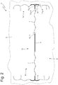
Figure 2 is a partial plan view of the cover panel ofFigure 1 illustrating the weakening; -
Figures 3-6 are enlarged scale views of respective details ofFigure 2 ; -
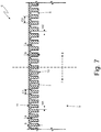
Figure 7 is a transverse sectional view of the cover panel ofFigure 1 at the weakening; -
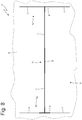
Figure 8 is a partial plan view of the cover panel ofFigure 1 illustrating a different embodiment of the weakening; -
Figure 9 is a plan view of the cover panel ofFigure 8 illustrating the position of a deployment channel of the underlying airbag; -
Figure 10 is a partial plan view of the cover panel ofFigure 1 illustrating a further embodiment of the weakening; and -
Figure 11 is a plan view of the cover panel ofFigure 10 illustrating the position of a deployment channel of the underlying airbag. - In
Figure 1 , reference numeral 1 indicates, as a whole, an automobile provided with acabin 2. - Some parts of the cabin 2 (in particular all parts of the dashboard 3) are covered by
corresponding cover panels 4 having externally a visible surface having a fine finish. For example, thecover panels 4 can be externally covered by a foam (cheapest solution), by fabrics (intermediate solution), or by leather (most expensive solution). - Arranged underneath at least one
cover panel 4 is acorresponding airbag 5 that is normally housed (when it has not been inflated, i.e. when it has not been activated yet) in its own housing. At theairbag 5, thecover panel 4 has a weakening 6 (illustrated inFigure 2 ) that delimits a lid that "pops" (i.e. opens) when the airbag inflates so as to allow the deployment of said airbag. - As illustrated in the accompanying figures, the
weakening 6 consists of a sequence of not-throughincisions 7 and 8 (better illustrated inFigure 7 ) which are separated from each other, are arranged along a weakeningline 9, are obtained from aninternal surface 10 of thecover panel 4, and terminate at a non-zero distance (illustrated inFigure 7 ) from anexternal surface 11 of thecover panel 4. When theincisions cover panel 4. - As better illustrated in
Figure 7 , all theincisions incisions incisions - Moreover, in some sections of the weakening
line 9 there areincisions 7 each having a width W1 (measured parallel to the cover panel 4) while in other sections of the weakeningline 9 there areincisions 8 each having a width W2 (measured parallel to the cover panel 4) greater than the width W1; i.e. theincisions - According to a preferred, but non-limiting, embodiment, the width W2 is between 1.4 and 1.6 times the width W1; in particular, the width W1 is between 0.15 and 0.25 times an overall thickness B of the
cover panel 4 while the width W2 is between 0.2 and 0.4 times the overall thickness B of thecover panel 4. - The
incisions 7 have a pitch C1 and theincisions 8 have a pitch C2 greater than the pitch C1; i.e. theincisions cover panel 4 while the pitch C1 is between 0.45 and 0.55 times the overall thickness B of thecover panel 4. - As illustrated in
Figure 2 , theweakening line 9 has an "H" shape having twoside portions 12 parallel to and opposite one another and anintermediate portion 13 that centrally connects the twoside portions 12 to one another; consequently, theweakening line 9 has two connection areas, in each of which theintermediate portion 13 connects to acorresponding side portion 12. Theincisions 8 are provided only in a central area (illustrated with a greater thickness inFigure 2 ) of theintermediate portion 13, and in the two connection areas (illustrated with a greater thickness inFigure 2 ) between theintermediate portion 13 and theside portions 12. In particular, in each connection area theincisions 8 are present both in theintermediate portion 13 and in theside portion 12 so that, in each connection area, theincisions 8 constitute a "T" shape (illustrated with a greater thickness inFigure 2 ). - According to a preferred, but non-limiting, embodiment, in the
intermediate portion 13 theweakening line 9 has a straight shape in correspondence with theincisions 8 and has a curved wave shape (in particular a sinusoid) in correspondence of theincisions 7. Moreover, eachside portion 12 has both straight and curved wave-shaped sections (in particular a sinusoid). In eachside portion 12 there are only two small straight-shaped sections arranged at the two ends, while eachside portion 12 has a curved wave shape, in particular a sinusoid, also at the connection area with theintermediate portion 13. - According to a preferred, but non-limiting, embodiment, at each
incision cover panel 4 has a residual thickness A between 0.15 and 0.2 times the overall thickness B of thecover panel 4. - The embodiment illustrated in
Figure 8 differs from the embodiment illustrated inFigure 2 by the absence of the curved wave shape in theweakening line 9 having an "H" shape; i.e., in the embodiment illustrated inFigure 8 , the weakening line 9 (having an "H" shape) is completely rectilinear everywhere (thus without curved wave-shaped sections). - As illustrated in
Figure 9 , the twoside portions 12 of the weakeningline 9 configured as an "H" are arranged further outwards with respect to the edge of adeployment channel 14 of theairbag 5; in particular, the twoside portions 12 of the weakeningline 9 configured as an "H" are arranged at a distance D (greater than 2 mm and preferably equal to 3 mm) from the edge of thedeployment channel 14 of theairbag 5. This way, it is possible to ensure a deployment of theairbag 5 with no obstacles in spite of (by compensating) all position tolerances of thecover panel 4 with respect to theairbag 5. Obviously, the same "tolerance" (i.e. a distance D greater than 2 mm between theside portions 12 of the weakeningline 9 from the edge of thedeployment channel 14 of the airbag 5) is preferably also provided in the embodiment illustrated inFigure 2 wherein theweakening line 9 has rectilinear sections with curved wave-shaped sections arranged between them. - The embodiment illustrated in
Figure 10 differs from the embodiment illustrated inFigures 2 and8 by the different configuration of the weakening line 9: in the embodiment illustrated inFigures 2 and8 , theweakening line 9 has an "H" shape constituted by twoside portions 12 connected to one another by anintermediate portion 13, while in the embodiment illustrated inFigure 10 theweakening line 9 has a "Y" shape (i.e. a "chalice" shape) constituted by abase portion 15, by anintermediate portion 16, and by two divergingportions 17 which originate at theintermediate portion 16 and diverge with respect to one another, thus forming a 90° angle between one another; consequently, the weakeningline 9 has two connection areas in which theintermediate portion 16 connects to thebase portion 15 and in which theintermediate portion 16 connects to the divergingportions 17. In particular, theintermediate portion 16 is perpendicular to thebase portion 15, connects to thebase portion 15 at a midpoint of thebase portion 15 and forms a 45° angle with eachdiverging portion 17. According to a different embodiment not illustrated, the angle between the two divergingportions 17 could be different from 90° (and, consequently, the angle formed between theintermediate portion 16 and each divergingportion 17 could be different from 45°). According to a different embodiment not illustrated, theweakening line 9 configured as a "Y" does not have thebase portion 15, i.e. is constituted by theintermediate portion 16 and by the two divergingportions 17 only; in this embodiment, there is only one connection area between theintermediate portion 16 and the two divergingportions 17. - As illustrated in
Figure 10 , theincisions 8 are only provided in the two connection areas (illustrated with a greater thickness inFigure 10 ) between theintermediate portion 16 and thebase portion 15 on one side and theintermediate portion 16 and the divergingportions 17 on the other side. In particular, in each connection area theincisions 8 are provided both in theintermediate portion 16 and in theportions incisions 8 constitute a "T" shape or a "Y" shape (illustrated with a greater thickness inFigure 10 ). - In the embodiment illustrated in
Figures 10 and11 , theweakening line 9 configured as a "Y" only has rectilinear sections; according to a different embodiment not illustrated, theweakening line 9 configured as a "Y" could have some rectilinear sections and some curved wave-shaped sections (as illustrated inFigure 2 ), i.e. could have rectilinear sections with curved wave-shaped sections arranged between them (as in the embodiment illustrated inFigure 2 ). - As illustrated in
Figure 11 , thebase portion 15 and the vertexes of the divergingportions 17 of theweakening line 9 configured as a "Y" are arranged further outwards with respect to the edge of thedeployment channel 14 of theairbag 5; in particular, thebase portion 15 and the vertexes of the divergingportions 17 of the weakeningline 9 configured as a "Y" are arranged at a distance D (greater than 2 mm and preferably equal to 3 mm) from the edge of thedeployment channel 14 of theairbag 5. This way, it is possible to ensure a deployment of theairbag 5 with no obstacles in spite of (by compensating) all tolerances relating to the positioning of thecover panel 4 with respect to theairbag 5. - Summarizing the foregoing, in some sections of the weakening
line 9 there are only "standard"incisions 7 each having the width W1, while in other sections of the weakeningline 9 there are only "augmented"incisions 8 each having the width W2 greater than the width W1; in particular, in each connection area, the corresponding portions 12-17 of theweakening line 9 consist of the "augmented"incisions 8 only while, next to each connection area, the corresponding portions 12-17 of theweakening line 9 consist of the "standard"incisions 7 only. In both configurations of the weakening line 9 (i.e. both in theweakening line 9 configured as an "H" and in theweakening line 9 configured as a "Y"), the "augmented" incisions are only present in each connection area and in a central area of theweakening line 9; in this regard, it is important to note that, in theweakening line 9 configured as a "Y", the central area of theweakening line 9 coincides with the connection area between thebase portion 15 and thediverging portions 17. - The
cover panel 4 having the weakening 6 can be made of any type of material such as, for example, a hard polyurethane foam. - The embodiments described herein can be combined with one another without departing from the scope of protection of the present invention.
- The
cover panel 4 described in the foregoing has numerous advantages. - First of all, the
cover panel 4 described in the foregoing allows an optimal opening of theunderlying airbag 5 and, simultaneously, does not show any trace of the weakening 6 (i.e. theweakening 6 is completely invisible for anyone inside thecabin 2 regardless of their point of view or the current illumination). - Moreover, the
weakening 6, while allowing an optimal opening of theunderlying airbag 5, ensures that the violent opening of theairbag 5 does not cause the detachment of parts of thecover panel 4 which could be thrust with violence against the occupants of the automobile 1. - Finally, the
cover panel 4 described in the foregoing is easy and inexpensive to manufacture as theweakening 6 can be made quickly by means of a laser cutting instrument (for example using the femtosecond technology) that is readily available on the market. -
- 1
- automobile
- 2
- cabin
- 3
- dashboard
- 4
- cover panel
- 5
- airbag
- 6
- weakening
- 7
- incisions
- 8
- incisions
- 9
- weakening line
- 10
- internal surface
- 11
- external surface
- 12
- side portions
- 13
- intermediate portion
- 14
- deployment channel
- 15
- base portion
- 16
- intermediate portion
- 17
- diverging portions
- A
- thickness
- B
- thickness
- C
- pitch
- W1
- width
- W2
- width
- D
- distance
Claims (17)
- A cover panel (4) for a cabin (2) of a vehicle (1) and provided with a weakening (6) for the opening of an underlying airbag (5); the weakening (6) consists of a sequence of not-through incisions (7, 8) which are separated from each other, are arranged along a weakening line (9), are obtained from an internal surface (10) of the cover panel (4), and terminate at a non-zero distance from an external surface (11) of the cover panel (4);
wherein in some sections of the weakening line (9) there are only first incisions (7) each having a first width (W1) while in other sections of the weakening line (9) there are only second incisions (8) each having a second width (W2) greater than the first width (W1); and
wherein the weakening line (9) comprises a plurality of portions (12-17) that connect to one another in at least one connection area;
the cover panel (4) is characterized in that, in each connection area, the corresponding portions (12-17) of the weakening line (9) consist of the second incisions (8) only while, next to each connection area, the corresponding portions (12-17) of the weakening line (9) consist of the first incisions (7) only. - The cover panel (4) according to claim 1, wherein:the weakening line (9) has an "H" shape comprising two side portions (12) parallel to each other and opposite one from the other and an intermediate portion (13) connecting centrally the two side portions (12); andthere are two connection areas in each of which the intermediate portion (13) connects to a corresponding side portion (12).
- The cover panel (4) according to claim 2, wherein a central area of the intermediate portion (13) also consists of the second incisions (8) only while, next to the central area, the intermediate portion (13) consists of the first incisions (7) only.
- The cover panel (4) according to claim 3, wherein the second incisions (8) are only present in the central area of the intermediate portion (13) and in the two connection areas between the intermediate portion (13) and the side portions (12).
- The cover panel (4) according to claim 2, 3 or 4, wherein the two side portions (12) of the weakening line (9) configured as an "H" are arranged at a distance (D) greater than 2 mm and preferably equal to 3 mm from an edge of a deployment channel (14) of the airbag (5).
- The cover panel (4) according to any one of claims 2 to 5, wherein in the intermediate portion (13) the weakening line (9) has a straight shape in correspondence with the second incisions (8) and has a curved wave shape, in particular sinusoidal shape, in correspondence of the first incisions (7).
- The cover panel (4) according to any one of claims 2 to 6, wherein each side portion (12) has both straight and curved wave-shaped sections, in particular sinusoidal shape.
- The cover panel (4) according to any one of claims 2 to 7, wherein each side portion (12) has a curved wave shape, in particular sinusoidal shape, at the connection area with the intermediate portion (13).
- The cover panel (4) according to claim 1, wherein:the weakening line (9) has a "Y" shape comprising an intermediate portion (16) and two diverging portions (17) that originate at the intermediate portion (16) and diverge with respect to one another; andthere is at least one connection area in which the intermediate portion (16) connects to the two diverging portions (17).
- The cover panel (4) according to claim 9, wherein:the weakening line (9) also comprises a base portion (15) ;the intermediate portion (16) is perpendicular to the base portion (15) and connects to the base portion (15) at a midpoint of the base portion (15); andthere are two connection areas in which the intermediate portion (16) connects to the two diverging portions (17) and in which the intermediate portion (16) connects to the base portion (15).
- The cover panel (4) according to claim 9 or 10, wherein the second incisions (8) are only provided in each connection area.
- The cover panel (4) according to claim 9, 10 or 11, wherein the base portion (15) and the vertexes of the diverging portions (17) of the weakening line (9) configured as a "Y" are arranged at a distance (D) greater than 2 mm and preferably equal to 3 mm from an edge of a deployment channel (14) of the airbag (5).
- The cover panel (4) according to any one of claims 1 to 12, wherein the second incisions (8) are only provided in each connection area and in a central area of the weakening line (9).
- The cover panel (4) according to any one of claims 1 to 13, wherein the weakening line (9) has rectilinear sections with curved wave-shaped, in particular sinusoidal, sections arranged between them.
- The cover panel (4) according to any one of claims 1 to 14, wherein:the second width (W2) is between 1.4 and 1.6 times the first width (W1);the first width (W1) is between 0.15 and 0.25 times an overall thickness (B) of the cover panel (4); andthe second width (W2) is between 0.2 and 0.4 times the overall thickness (B) of the cover panel (4).
- The cover panel (4) according to any one of claims 1 to 15, wherein the first incisions (7) have a first pitch (C1) and the second incisions (8) have a second pitch (C2) greater than the first pitch (C1), preferably between 1.3 and 1.4 times the first pitch (C1).
- The cover panel (4) according to any of claims 1 to 16, wherein the first incisions (7) and the second incisions (9) all have the same depth.
Applications Claiming Priority (1)
| Application Number | Priority Date | Filing Date | Title |
|---|---|---|---|
| IT102020000015523A IT202000015523A1 (en) | 2020-06-26 | 2020-06-26 | COVER PANEL FOR A VEHICLE COMPARTMENT AND PROVIDED WITH A WEAKENING FOR THE OPENING OF AN UNDERLYING AIRBAG |
Publications (2)
| Publication Number | Publication Date |
|---|---|
| EP3929038A1 true EP3929038A1 (en) | 2021-12-29 |
| EP3929038B1 EP3929038B1 (en) | 2023-07-26 |
Family
ID=72473811
Family Applications (1)
| Application Number | Title | Priority Date | Filing Date |
|---|---|---|---|
| EP21181670.7A Active EP3929038B1 (en) | 2020-06-26 | 2021-06-25 | Cover panel for a cabin of a vehicle and provided with a weakening for the opening of an underlying airbag |
Country Status (5)
| Country | Link |
|---|---|
| US (1) | US11505157B2 (en) |
| EP (1) | EP3929038B1 (en) |
| JP (1) | JP7751406B2 (en) |
| CN (1) | CN113928258B (en) |
| IT (1) | IT202000015523A1 (en) |
Families Citing this family (6)
| Publication number | Priority date | Publication date | Assignee | Title |
|---|---|---|---|---|
| JP7734418B2 (en) * | 2022-01-21 | 2025-09-05 | 株式会社ソフイア | gaming machines |
| JP7734417B2 (en) * | 2022-01-21 | 2025-09-05 | 株式会社ソフイア | gaming machines |
| JP7734419B2 (en) * | 2022-01-21 | 2025-09-05 | 株式会社ソフイア | gaming machines |
| CN119497688A (en) * | 2022-07-11 | 2025-02-21 | 延锋国际汽车技术有限公司 | Components for vehicle interior |
| US12304414B1 (en) * | 2024-03-28 | 2025-05-20 | Ford Global Technologies, Llc | Vehicle instrument panel and foldable airbag deployment door |
| DE102024120085A1 (en) * | 2024-07-15 | 2026-01-15 | Dr. Ing. H.C. F. Porsche Aktiengesellschaft | Vehicle instrument panel |
Citations (12)
| Publication number | Priority date | Publication date | Assignee | Title |
|---|---|---|---|---|
| EP0771695A1 (en) | 1995-10-31 | 1997-05-07 | Deutsche Fibrit Gesellschaft Ebers & Dr. Müller mbH | Interior trim panel |
| DE19636428A1 (en) | 1996-09-07 | 1998-03-12 | Jenoptik Jena Gmbh | Airbag cover |
| US6113131A (en) * | 1997-05-02 | 2000-09-05 | Kansei Corporation | Instrument panel |
| USRE36898E (en) * | 1988-12-26 | 2000-10-03 | Takata Corporation | Cover for a vehicle air bag |
| EP1213193A1 (en) | 2000-12-09 | 2002-06-12 | Eissmann GmbH | Covering for a dashboard, a steering wheel or the like |
| EP1520754A1 (en) * | 2003-09-30 | 2005-04-06 | Nihon Plast Co., Ltd. | Airbag cover and its production process |
| US20060033313A1 (en) * | 2004-08-16 | 2006-02-16 | Moriroku Kabushiki Kaisha | Vehicle airbag system |
| WO2006111212A1 (en) | 2005-04-20 | 2006-10-26 | Eissmann Automotive Deutschland Gmbh | Cover for an airbag and method for the production thereof |
| DE102006059212A1 (en) | 2006-12-13 | 2008-06-19 | Eissmann Automotive Deutschland Gmbh | Method for marking weakened leather used as a cover for an airbag comprises using a pressure-less process as a chemical and/or physical change to mark the leather on its rear side in the region of fibrous layers of the leather |
| US20110211927A1 (en) | 2008-10-30 | 2011-09-01 | Faurecia Interieur Industrie | Process for manufacturing an automobile interior trim part with an airbag cover and to the associated machine |
| WO2015154898A1 (en) | 2014-04-07 | 2015-10-15 | Eissmann Automotive Deutschland Gmbh | Cover for an airbag, comprising a decorative layer made of leather, and method for manufacturing same |
| DE102015111590B3 (en) | 2015-07-16 | 2016-11-24 | Eissmann Automotive Deutschland Gmbh | A method for producing a decorative composite with at least one local weakening and a weakened spacer knitted fabric |
Family Cites Families (29)
| Publication number | Priority date | Publication date | Assignee | Title |
|---|---|---|---|---|
| JP3225698B2 (en) * | 1993-07-15 | 2001-11-05 | 日産自動車株式会社 | Airbag device |
| DE19646548C2 (en) * | 1996-10-31 | 1998-08-27 | Sommer Allibert Lignotock Gmbh | Interior trim part for motor vehicles with airbag equipment |
| GB9714114D0 (en) * | 1997-07-03 | 1997-09-10 | Sanko Gosei Uk Ltd | Air bag |
| JP2001106010A (en) * | 1999-10-06 | 2001-04-17 | Toyota Central Res & Dev Lab Inc | Airbag module cover |
| DE10227118A1 (en) * | 2002-06-14 | 2004-01-15 | Jenoptik Automatisierungstechnik Gmbh | Method for introducing a line of weakness of low tear strength into an airbag cover and airbag cover produced therewith |
| JP2004331046A (en) * | 2003-04-15 | 2004-11-25 | Takata Corp | Cover component for airbag device, air bag device and interior member for vehicle |
| JP4401129B2 (en) * | 2003-09-04 | 2010-01-20 | タカタ株式会社 | Airbag cover, airbag module |
| JP4478826B2 (en) * | 2003-11-21 | 2010-06-09 | 株式会社イノアックコーポレーション | Skin material and molding method thereof |
| JP4368186B2 (en) * | 2003-12-03 | 2009-11-18 | 芦森工業株式会社 | Air grid |
| US7121578B2 (en) * | 2003-12-22 | 2006-10-17 | Lear Corporation | Trim panel having foam bridge supported hidden tear seam |
| JP2005219572A (en) * | 2004-02-04 | 2005-08-18 | Sanko Gosei Ltd | Air bag device for automobile |
| US20060186646A1 (en) * | 2005-02-18 | 2006-08-24 | Takata Restraint Systems, Inc. | Air bag module cover with lateral opening air bag door |
| JP4668669B2 (en) * | 2005-04-14 | 2011-04-13 | 日本プラスト株式会社 | Automotive interior panels |
| JP4831999B2 (en) * | 2005-05-31 | 2011-12-07 | 三光合成株式会社 | VEHICLE AIRBACK DEVICE AND AIRBACK COVER |
| JP4918820B2 (en) * | 2006-07-31 | 2012-04-18 | トヨタ車体株式会社 | Tearline break control method and airbag door tearline |
| DE102006054592B3 (en) * | 2006-11-20 | 2008-02-14 | Lisa Dräxlmaier GmbH | Automotive interior trim panel has laser cut perforations in the surface layer, upholstery layer and substrate layer |
| DE102007013108B3 (en) * | 2007-03-15 | 2008-08-07 | Jenoptik Automatisierungstechnik Gmbh | Method for producing an at least two-layer vehicle interior trim part with integrated airbag cover and vehicle interior trim part |
| FR2916175B1 (en) * | 2007-05-16 | 2009-11-27 | Faurecia Interieur Ind | CLOTHING ELEMENT OF THE INTERIOR OF A MOTOR VEHICLE. |
| JP5194662B2 (en) * | 2007-09-13 | 2013-05-08 | トヨタ車体株式会社 | Airbag door |
| EP2527208B1 (en) * | 2011-05-26 | 2013-10-23 | International Automotive Components Group GmbH | Airbag cover, in particular for airbags in a motor vehicle and method for producing same |
| JP2015020568A (en) * | 2013-07-18 | 2015-02-02 | 日本Iac株式会社 | Car interior parts |
| JP6239348B2 (en) * | 2013-11-15 | 2017-11-29 | 芦森工業株式会社 | Airbag device |
| JP2017114262A (en) * | 2015-12-24 | 2017-06-29 | 日本プラスト株式会社 | Cover body for air bag device |
| DE102016001647A1 (en) * | 2016-02-12 | 2016-09-15 | Daimler Ag | Method for producing a trim part for a vehicle and trim part |
| US9771044B1 (en) * | 2016-04-25 | 2017-09-26 | Ford Global Technologies, Llc | Leather trim panel skin hidden tear seam with disrupted fiber matrix |
| CN107791990A (en) * | 2016-08-29 | 2018-03-13 | 成都航天模塑股份有限公司 | A kind of dashboard airbag weakening structure |
| US10640837B2 (en) * | 2017-09-27 | 2020-05-05 | Faurecia Interior Systems, Inc. | Vehicle interior panel with laser-formed tear seam |
| US11420580B2 (en) * | 2018-08-06 | 2022-08-23 | Honda Motor Co., Ltd. | Instrument panel and method for manufacturing instrument panel |
| CN111391777B (en) * | 2020-04-23 | 2022-06-14 | 上海延锋金桥汽车饰件系统有限公司 | Skin for automotive upholstery |
-
2020
- 2020-06-26 IT IT102020000015523A patent/IT202000015523A1/en unknown
-
2021
- 2021-06-24 CN CN202110704377.5A patent/CN113928258B/en active Active
- 2021-06-24 US US17/357,114 patent/US11505157B2/en active Active
- 2021-06-25 JP JP2021105421A patent/JP7751406B2/en active Active
- 2021-06-25 EP EP21181670.7A patent/EP3929038B1/en active Active
Patent Citations (12)
| Publication number | Priority date | Publication date | Assignee | Title |
|---|---|---|---|---|
| USRE36898E (en) * | 1988-12-26 | 2000-10-03 | Takata Corporation | Cover for a vehicle air bag |
| EP0771695A1 (en) | 1995-10-31 | 1997-05-07 | Deutsche Fibrit Gesellschaft Ebers & Dr. Müller mbH | Interior trim panel |
| DE19636428A1 (en) | 1996-09-07 | 1998-03-12 | Jenoptik Jena Gmbh | Airbag cover |
| US6113131A (en) * | 1997-05-02 | 2000-09-05 | Kansei Corporation | Instrument panel |
| EP1213193A1 (en) | 2000-12-09 | 2002-06-12 | Eissmann GmbH | Covering for a dashboard, a steering wheel or the like |
| EP1520754A1 (en) * | 2003-09-30 | 2005-04-06 | Nihon Plast Co., Ltd. | Airbag cover and its production process |
| US20060033313A1 (en) * | 2004-08-16 | 2006-02-16 | Moriroku Kabushiki Kaisha | Vehicle airbag system |
| WO2006111212A1 (en) | 2005-04-20 | 2006-10-26 | Eissmann Automotive Deutschland Gmbh | Cover for an airbag and method for the production thereof |
| DE102006059212A1 (en) | 2006-12-13 | 2008-06-19 | Eissmann Automotive Deutschland Gmbh | Method for marking weakened leather used as a cover for an airbag comprises using a pressure-less process as a chemical and/or physical change to mark the leather on its rear side in the region of fibrous layers of the leather |
| US20110211927A1 (en) | 2008-10-30 | 2011-09-01 | Faurecia Interieur Industrie | Process for manufacturing an automobile interior trim part with an airbag cover and to the associated machine |
| WO2015154898A1 (en) | 2014-04-07 | 2015-10-15 | Eissmann Automotive Deutschland Gmbh | Cover for an airbag, comprising a decorative layer made of leather, and method for manufacturing same |
| DE102015111590B3 (en) | 2015-07-16 | 2016-11-24 | Eissmann Automotive Deutschland Gmbh | A method for producing a decorative composite with at least one local weakening and a weakened spacer knitted fabric |
Also Published As
| Publication number | Publication date |
|---|---|
| CN113928258B (en) | 2025-01-28 |
| JP2022008255A (en) | 2022-01-13 |
| EP3929038B1 (en) | 2023-07-26 |
| CN113928258A (en) | 2022-01-14 |
| US11505157B2 (en) | 2022-11-22 |
| IT202000015523A1 (en) | 2021-12-26 |
| US20210402944A1 (en) | 2021-12-30 |
| JP7751406B2 (en) | 2025-10-08 |
Similar Documents
| Publication | Publication Date | Title |
|---|---|---|
| US11505157B2 (en) | Cover panel for a cabin of a vehicle and provided with a weakening for the opening of an underlying airbag | |
| US8814207B2 (en) | Instrument panel integrally including an airbag door | |
| US8567814B2 (en) | Patterned weakening of airbag coverings | |
| EP2722238B1 (en) | Vehicle interior panel and vehicle airbag device | |
| JP2007512997A (en) | Instrument panel system with a hidden airbag door | |
| US20120223512A1 (en) | Angled tear seams for airbag covers | |
| US6921105B2 (en) | Integrally molded passenger airbag cover | |
| US9694780B1 (en) | Airbag cover with breakaway-resistant features | |
| US20050275197A1 (en) | Airbag cover and airbag system | |
| CN105270312A (en) | Interior panels having integrated airbag doors for motor vehicles and methods for making the same | |
| EP2460696A1 (en) | Improved tear seams for airbag covers | |
| US8844965B2 (en) | Airbag tear seam shapes | |
| US7384061B2 (en) | Trim panel and a method of manufacture | |
| US5286055A (en) | Modular cover for an air bag assembly | |
| US11820316B2 (en) | Airbag cushion with flexible diffusor- and tether arrangement and method for its production | |
| US12083984B2 (en) | Airbag assembly for a vehicle | |
| US11891011B1 (en) | Airbag tear seam | |
| US20220126764A1 (en) | Skin member | |
| JP2013047087A (en) | Airbag cover | |
| JP2006062422A (en) | Airbag door | |
| US11932193B1 (en) | Vehicle interior panel for use over a deployable airbag and method of manufacturing | |
| JP2007030841A (en) | Airbag door | |
| KR20020089062A (en) | An air bag cover of an automobile | |
| MXPA00007954A (en) | Integral airbag door and method of making |
Legal Events
| Date | Code | Title | Description |
|---|---|---|---|
| PUAI | Public reference made under article 153(3) epc to a published international application that has entered the european phase |
Free format text: ORIGINAL CODE: 0009012 |
|
| STAA | Information on the status of an ep patent application or granted ep patent |
Free format text: STATUS: THE APPLICATION HAS BEEN PUBLISHED |
|
| AK | Designated contracting states |
Kind code of ref document: A1 Designated state(s): AL AT BE BG CH CY CZ DE DK EE ES FI FR GB GR HR HU IE IS IT LI LT LU LV MC MK MT NL NO PL PT RO RS SE SI SK SM TR |
|
| B565 | Issuance of search results under rule 164(2) epc |
Effective date: 20210922 |
|
| STAA | Information on the status of an ep patent application or granted ep patent |
Free format text: STATUS: REQUEST FOR EXAMINATION WAS MADE |
|
| 17P | Request for examination filed |
Effective date: 20220620 |
|
| GRAP | Despatch of communication of intention to grant a patent |
Free format text: ORIGINAL CODE: EPIDOSNIGR1 |
|
| STAA | Information on the status of an ep patent application or granted ep patent |
Free format text: STATUS: GRANT OF PATENT IS INTENDED |
|
| INTG | Intention to grant announced |
Effective date: 20230125 |
|
| GRAS | Grant fee paid |
Free format text: ORIGINAL CODE: EPIDOSNIGR3 |
|
| GRAA | (expected) grant |
Free format text: ORIGINAL CODE: 0009210 |
|
| STAA | Information on the status of an ep patent application or granted ep patent |
Free format text: STATUS: THE PATENT HAS BEEN GRANTED |
|
| P01 | Opt-out of the competence of the unified patent court (upc) registered |
Effective date: 20230525 |
|
| AK | Designated contracting states |
Kind code of ref document: B1 Designated state(s): AL AT BE BG CH CY CZ DE DK EE ES FI FR GB GR HR HU IE IS IT LI LT LU LV MC MK MT NL NO PL PT RO RS SE SI SK SM TR |
|
| REG | Reference to a national code |
Ref country code: CH Ref legal event code: EP |
|
| REG | Reference to a national code |
Ref country code: DE Ref legal event code: R096 Ref document number: 602021003746 Country of ref document: DE |
|
| REG | Reference to a national code |
Ref country code: IE Ref legal event code: FG4D |
|
| REG | Reference to a national code |
Ref country code: LT Ref legal event code: MG9D |
|
| REG | Reference to a national code |
Ref country code: NL Ref legal event code: MP Effective date: 20230726 |
|
| REG | Reference to a national code |
Ref country code: AT Ref legal event code: MK05 Ref document number: 1591622 Country of ref document: AT Kind code of ref document: T Effective date: 20230726 |
|
| PG25 | Lapsed in a contracting state [announced via postgrant information from national office to epo] |
Ref country code: NL Free format text: LAPSE BECAUSE OF FAILURE TO SUBMIT A TRANSLATION OF THE DESCRIPTION OR TO PAY THE FEE WITHIN THE PRESCRIBED TIME-LIMIT Effective date: 20230726 |
|
| PG25 | Lapsed in a contracting state [announced via postgrant information from national office to epo] |
Ref country code: GR Free format text: LAPSE BECAUSE OF FAILURE TO SUBMIT A TRANSLATION OF THE DESCRIPTION OR TO PAY THE FEE WITHIN THE PRESCRIBED TIME-LIMIT Effective date: 20231027 |
|
| PG25 | Lapsed in a contracting state [announced via postgrant information from national office to epo] |
Ref country code: IS Free format text: LAPSE BECAUSE OF FAILURE TO SUBMIT A TRANSLATION OF THE DESCRIPTION OR TO PAY THE FEE WITHIN THE PRESCRIBED TIME-LIMIT Effective date: 20231126 |
|
| PG25 | Lapsed in a contracting state [announced via postgrant information from national office to epo] |
Ref country code: SE Free format text: LAPSE BECAUSE OF FAILURE TO SUBMIT A TRANSLATION OF THE DESCRIPTION OR TO PAY THE FEE WITHIN THE PRESCRIBED TIME-LIMIT Effective date: 20230726 Ref country code: RS Free format text: LAPSE BECAUSE OF FAILURE TO SUBMIT A TRANSLATION OF THE DESCRIPTION OR TO PAY THE FEE WITHIN THE PRESCRIBED TIME-LIMIT Effective date: 20230726 Ref country code: PT Free format text: LAPSE BECAUSE OF FAILURE TO SUBMIT A TRANSLATION OF THE DESCRIPTION OR TO PAY THE FEE WITHIN THE PRESCRIBED TIME-LIMIT Effective date: 20231127 Ref country code: NO Free format text: LAPSE BECAUSE OF FAILURE TO SUBMIT A TRANSLATION OF THE DESCRIPTION OR TO PAY THE FEE WITHIN THE PRESCRIBED TIME-LIMIT Effective date: 20231026 Ref country code: LV Free format text: LAPSE BECAUSE OF FAILURE TO SUBMIT A TRANSLATION OF THE DESCRIPTION OR TO PAY THE FEE WITHIN THE PRESCRIBED TIME-LIMIT Effective date: 20230726 Ref country code: LT Free format text: LAPSE BECAUSE OF FAILURE TO SUBMIT A TRANSLATION OF THE DESCRIPTION OR TO PAY THE FEE WITHIN THE PRESCRIBED TIME-LIMIT Effective date: 20230726 Ref country code: IS Free format text: LAPSE BECAUSE OF FAILURE TO SUBMIT A TRANSLATION OF THE DESCRIPTION OR TO PAY THE FEE WITHIN THE PRESCRIBED TIME-LIMIT Effective date: 20231126 Ref country code: HR Free format text: LAPSE BECAUSE OF FAILURE TO SUBMIT A TRANSLATION OF THE DESCRIPTION OR TO PAY THE FEE WITHIN THE PRESCRIBED TIME-LIMIT Effective date: 20230726 Ref country code: GR Free format text: LAPSE BECAUSE OF FAILURE TO SUBMIT A TRANSLATION OF THE DESCRIPTION OR TO PAY THE FEE WITHIN THE PRESCRIBED TIME-LIMIT Effective date: 20231027 Ref country code: FI Free format text: LAPSE BECAUSE OF FAILURE TO SUBMIT A TRANSLATION OF THE DESCRIPTION OR TO PAY THE FEE WITHIN THE PRESCRIBED TIME-LIMIT Effective date: 20230726 Ref country code: AT Free format text: LAPSE BECAUSE OF FAILURE TO SUBMIT A TRANSLATION OF THE DESCRIPTION OR TO PAY THE FEE WITHIN THE PRESCRIBED TIME-LIMIT Effective date: 20230726 |
|
| PG25 | Lapsed in a contracting state [announced via postgrant information from national office to epo] |
Ref country code: PL Free format text: LAPSE BECAUSE OF FAILURE TO SUBMIT A TRANSLATION OF THE DESCRIPTION OR TO PAY THE FEE WITHIN THE PRESCRIBED TIME-LIMIT Effective date: 20230726 |
|
| PG25 | Lapsed in a contracting state [announced via postgrant information from national office to epo] |
Ref country code: ES Free format text: LAPSE BECAUSE OF FAILURE TO SUBMIT A TRANSLATION OF THE DESCRIPTION OR TO PAY THE FEE WITHIN THE PRESCRIBED TIME-LIMIT Effective date: 20230726 |
|
| REG | Reference to a national code |
Ref country code: DE Ref legal event code: R097 Ref document number: 602021003746 Country of ref document: DE |
|
| PG25 | Lapsed in a contracting state [announced via postgrant information from national office to epo] |
Ref country code: SM Free format text: LAPSE BECAUSE OF FAILURE TO SUBMIT A TRANSLATION OF THE DESCRIPTION OR TO PAY THE FEE WITHIN THE PRESCRIBED TIME-LIMIT Effective date: 20230726 Ref country code: RO Free format text: LAPSE BECAUSE OF FAILURE TO SUBMIT A TRANSLATION OF THE DESCRIPTION OR TO PAY THE FEE WITHIN THE PRESCRIBED TIME-LIMIT Effective date: 20230726 Ref country code: ES Free format text: LAPSE BECAUSE OF FAILURE TO SUBMIT A TRANSLATION OF THE DESCRIPTION OR TO PAY THE FEE WITHIN THE PRESCRIBED TIME-LIMIT Effective date: 20230726 Ref country code: EE Free format text: LAPSE BECAUSE OF FAILURE TO SUBMIT A TRANSLATION OF THE DESCRIPTION OR TO PAY THE FEE WITHIN THE PRESCRIBED TIME-LIMIT Effective date: 20230726 Ref country code: DK Free format text: LAPSE BECAUSE OF FAILURE TO SUBMIT A TRANSLATION OF THE DESCRIPTION OR TO PAY THE FEE WITHIN THE PRESCRIBED TIME-LIMIT Effective date: 20230726 Ref country code: CZ Free format text: LAPSE BECAUSE OF FAILURE TO SUBMIT A TRANSLATION OF THE DESCRIPTION OR TO PAY THE FEE WITHIN THE PRESCRIBED TIME-LIMIT Effective date: 20230726 Ref country code: SK Free format text: LAPSE BECAUSE OF FAILURE TO SUBMIT A TRANSLATION OF THE DESCRIPTION OR TO PAY THE FEE WITHIN THE PRESCRIBED TIME-LIMIT Effective date: 20230726 |
|
| PLBE | No opposition filed within time limit |
Free format text: ORIGINAL CODE: 0009261 |
|
| STAA | Information on the status of an ep patent application or granted ep patent |
Free format text: STATUS: NO OPPOSITION FILED WITHIN TIME LIMIT |
|
| 26N | No opposition filed |
Effective date: 20240429 |
|
| PG25 | Lapsed in a contracting state [announced via postgrant information from national office to epo] |
Ref country code: SI Free format text: LAPSE BECAUSE OF FAILURE TO SUBMIT A TRANSLATION OF THE DESCRIPTION OR TO PAY THE FEE WITHIN THE PRESCRIBED TIME-LIMIT Effective date: 20230726 |
|
| PG25 | Lapsed in a contracting state [announced via postgrant information from national office to epo] |
Ref country code: BG Free format text: LAPSE BECAUSE OF FAILURE TO SUBMIT A TRANSLATION OF THE DESCRIPTION OR TO PAY THE FEE WITHIN THE PRESCRIBED TIME-LIMIT Effective date: 20230726 |
|
| PG25 | Lapsed in a contracting state [announced via postgrant information from national office to epo] |
Ref country code: BG Free format text: LAPSE BECAUSE OF FAILURE TO SUBMIT A TRANSLATION OF THE DESCRIPTION OR TO PAY THE FEE WITHIN THE PRESCRIBED TIME-LIMIT Effective date: 20230726 |
|
| PG25 | Lapsed in a contracting state [announced via postgrant information from national office to epo] |
Ref country code: MC Free format text: LAPSE BECAUSE OF FAILURE TO SUBMIT A TRANSLATION OF THE DESCRIPTION OR TO PAY THE FEE WITHIN THE PRESCRIBED TIME-LIMIT Effective date: 20230726 |
|
| REG | Reference to a national code |
Ref country code: CH Ref legal event code: PL |
|
| PG25 | Lapsed in a contracting state [announced via postgrant information from national office to epo] |
Ref country code: LU Free format text: LAPSE BECAUSE OF NON-PAYMENT OF DUE FEES Effective date: 20240625 |
|
| PG25 | Lapsed in a contracting state [announced via postgrant information from national office to epo] |
Ref country code: IE Free format text: LAPSE BECAUSE OF NON-PAYMENT OF DUE FEES Effective date: 20240625 |
|
| PG25 | Lapsed in a contracting state [announced via postgrant information from national office to epo] |
Ref country code: BE Free format text: LAPSE BECAUSE OF NON-PAYMENT OF DUE FEES Effective date: 20240630 Ref country code: CH Free format text: LAPSE BECAUSE OF NON-PAYMENT OF DUE FEES Effective date: 20240630 |
|
| REG | Reference to a national code |
Ref country code: BE Ref legal event code: MM Effective date: 20240630 |
|
| PGFP | Annual fee paid to national office [announced via postgrant information from national office to epo] |
Ref country code: DE Payment date: 20250626 Year of fee payment: 5 |
|
| PGFP | Annual fee paid to national office [announced via postgrant information from national office to epo] |
Ref country code: GB Payment date: 20250617 Year of fee payment: 5 |
|
| PGFP | Annual fee paid to national office [announced via postgrant information from national office to epo] |
Ref country code: FR Payment date: 20250624 Year of fee payment: 5 |
|
| PGFP | Annual fee paid to national office [announced via postgrant information from national office to epo] |
Ref country code: IT Payment date: 20250611 Year of fee payment: 5 |
|
| PG25 | Lapsed in a contracting state [announced via postgrant information from national office to epo] |
Ref country code: CY Free format text: LAPSE BECAUSE OF FAILURE TO SUBMIT A TRANSLATION OF THE DESCRIPTION OR TO PAY THE FEE WITHIN THE PRESCRIBED TIME-LIMIT; INVALID AB INITIO Effective date: 20210625 |
|
| PG25 | Lapsed in a contracting state [announced via postgrant information from national office to epo] |
Ref country code: HU Free format text: LAPSE BECAUSE OF FAILURE TO SUBMIT A TRANSLATION OF THE DESCRIPTION OR TO PAY THE FEE WITHIN THE PRESCRIBED TIME-LIMIT; INVALID AB INITIO Effective date: 20210625 |