JP2017114262A - Cover body for air bag device - Google Patents

Cover body for air bag device Download PDF

Info

Publication number
JP2017114262A
JP2017114262A JP2015251325A JP2015251325A JP2017114262A JP 2017114262 A JP2017114262 A JP 2017114262A JP 2015251325 A JP2015251325 A JP 2015251325A JP 2015251325 A JP2015251325 A JP 2015251325A JP 2017114262 A JP2017114262 A JP 2017114262A
Authority
JP
Japan
Prior art keywords
cover body
skin
airbag
epidermis
tear line
Prior art date
Legal status (The legal status is an assumption and is not a legal conclusion. Google has not performed a legal analysis and makes no representation as to the accuracy of the status listed.)
Pending
Application number
JP2015251325A
Other languages
Japanese (ja)
Inventor
克弥 村松
Katsuya Muramatsu
克弥 村松
恭平 井出
Kyohei Ide
恭平 井出
Current Assignee (The listed assignees may be inaccurate. Google has not performed a legal analysis and makes no representation or warranty as to the accuracy of the list.)
Nihon Plast Co Ltd
Original Assignee
Nihon Plast Co Ltd
Priority date (The priority date is an assumption and is not a legal conclusion. Google has not performed a legal analysis and makes no representation as to the accuracy of the date listed.)
Filing date
Publication date
Application filed by Nihon Plast Co Ltd filed Critical Nihon Plast Co Ltd
Priority to JP2015251325A priority Critical patent/JP2017114262A/en
Publication of JP2017114262A publication Critical patent/JP2017114262A/en
Pending legal-status Critical Current

Links

Images

Abstract

PROBLEM TO BE SOLVED: To provide a cover body for an air bag device, which is capable of preventing deformation of a cover main body and peeling of a skin body from the cover main body caused by the contraction stress of the skin body.SOLUTION: A thin part 64 that absorbs contraction stress is provided at a position opposed to an extension plate part provided to extend to the outer edge of the front plate part of a cover main body 26. A skin part 27 extends at the position of the thin part 64 by contraction stress generated toward the center of the skin body 27 by heating, and thus the contraction stress can be effectively absorbed and softened. Deformation of the cover main body 26 and peeling of the skin body 27 from the cover main body 26 caused by the contraction stress of the skin body 27 can be prevented.SELECTED DRAWING: Figure 1

Description

本発明は、カバー本体の意匠面の少なくとも一部を覆って配置された表皮体を備えるエアバッグ装置のカバー体に関する。   The present invention relates to a cover body of an airbag device including an outer skin body that is disposed so as to cover at least a part of a design surface of a cover body.

従来、自動車などの車両のハンドルの固定部に備えられるエアバッグ装置が用いられている。このエアバッグ装置は、袋状のエアバッグと、このエアバッグにガスを供給するインフレータと、エアバッグを非展開時に覆って収納するカバー体とを備えている。そして、車両が例えば衝突などにより衝撃を受けた際に、インフレータからエアバッグへとガスが供給されることでエアバッグが膨張し、このエアバッグの膨張によりカバー体が予め設けられた破断線すなわちテアラインに沿って破断して複数の扉部が形成され、これら扉部がそれぞれヒンジ部を中心として展開することにより、エアバッグが乗員側に展開して、乗員を拘束して保護するように構成されている。   2. Description of the Related Art Conventionally, an airbag device provided in a fixed part of a handle of a vehicle such as an automobile has been used. The airbag device includes a bag-shaped airbag, an inflator that supplies gas to the airbag, and a cover body that covers and stores the airbag when not deployed. When the vehicle receives an impact due to, for example, a collision, the air bag is inflated by supplying gas from the inflator to the air bag. A plurality of door portions are formed by breaking along the tear line, and the door portions are deployed around the hinge portion, so that the airbag is deployed to the occupant side to restrain and protect the occupant. Has been.

近年、エアバッグカバー本体の表面に皮革などの表皮体を貼ることにより高級感を演出し商品性を高めるものが知られている。このような表皮体は、エアバッグカバー本体に設けられたテアラインに対応する位置に凹部が形成され、この凹部の形成部分を薄肉部としている。このため、エアバッグカバー本体のテアラインと表皮体の薄肉部とを重ね合わせて配置することで、エアバッグ展開時に表皮体が障害となることなくエアバッグカバーを開裂させることができるように構成されている(例えば、特許文献1及び2参照。)。   2. Description of the Related Art In recent years, there has been known a technique for producing a high-class feeling and improving merchantability by applying a skin body such as leather to the surface of an airbag cover body. In such an epidermis, a recess is formed at a position corresponding to a tear line provided in the airbag cover body, and a portion where the recess is formed is a thin-walled portion. For this reason, by arranging the tear line of the airbag cover main body and the thin portion of the epidermis so as to overlap each other, the airbag cover can be cleaved without causing the epidermis to become an obstacle when the airbag is deployed. (For example, refer to Patent Documents 1 and 2.)

特開平9−183373号公報 (第3頁、図1−4)JP 9-183373 A (page 3, Fig. 1-4) 特許第4093086号公報 (第4−7頁、図4)Japanese Patent No. 4093086 (page 4-7, FIG. 4)

しかしながら、エアバッグカバーをエアバッグカバー本体と表皮体との2層構造とした場合、例えば夏の炎天下などに自動車を駐車したときなどに、加熱された表皮体が収縮する力と、合成樹脂製のエアバッグカバー本体の熱膨張とによって、エアバッグカバーが変形するおそれがあるので、このような変形を防止するために、エアバッグカバー本体の剛性を高める必要がある。その場合、例えばガラス入りナイロンなどの高価な材料を用いなければならず、結果として製造コストを低減することが容易でない。   However, when the airbag cover has a two-layer structure of the airbag cover body and the skin body, for example, when a car is parked under a hot summer sun, the heated skin body contracts and the synthetic resin is used. Since the airbag cover may be deformed by the thermal expansion of the airbag cover body, it is necessary to increase the rigidity of the airbag cover body in order to prevent such deformation. In that case, for example, expensive materials such as glass-filled nylon must be used, and as a result, it is not easy to reduce the manufacturing cost.

本発明は、このような点に鑑みなされたもので、表皮体の収縮応力に起因するカバー本体の変形及び表皮体のカバー本体からの剥がれを防止できるエアバッグ装置のカバー体を提供することを目的とする。   The present invention has been made in view of the above points, and provides a cover body of an airbag device capable of preventing deformation of the cover body and peeling of the skin body from the cover body due to the contraction stress of the skin body. Objective.

請求項1記載のエアバッグ装置のカバー体は、カバー本体と、このカバー本体の意匠面の少なくとも一部を覆って配置された表皮体とを具備し、前記カバー本体は、収納されたエアバッグを覆う本体部と、この本体部の外縁部に延設され、この本体部とともに前記意匠面の少なくとも一部を構成する延設部とを備え、前記表皮体は、前記延設部に対向する位置に設けられ、収縮応力を吸収する収縮応力吸収部を備えたものである。   The cover body of the airbag device according to claim 1 includes a cover body and a skin body disposed so as to cover at least a part of a design surface of the cover body, and the cover body includes a stored airbag. A body portion that covers the outer edge portion of the body portion, and an extension portion that forms at least a part of the design surface together with the body portion, and the skin body faces the extension portion. It is provided with a contraction stress absorbing portion that is provided at a position and absorbs contraction stress.

請求項2記載のエアバッグ装置のカバー体は、請求項1記載のエアバッグ装置のカバー体において、カバー本体は、本体部のエアバッグに対向する側に設けられ、前記エアバッグの膨張展開時に開裂して複数の扉部を形成するテアラインを備え、表皮体は、前記テアラインに沿って破断可能な破断予定部を備え、収縮応力吸収部は、前記破断予定部に対して離間された位置に設けられたものである。   The cover body of the airbag device according to claim 2 is the cover body of the airbag device according to claim 1, wherein the cover body is provided on a side of the body portion facing the airbag, and when the airbag is inflated and deployed. The tear body is provided with a tear line that can be cleaved to form a plurality of door portions, the epidermis includes a planned breakable portion that can be broken along the tear line, and the shrinkage stress absorbing portion is spaced from the planned break portion. It is provided.

請求項3記載のエアバッグ装置のカバー体は、請求項1または2記載のエアバッグ装置のカバー体において、収縮応力吸収部は、延設部の輪郭に対して平行な方向と交差する方向とのいずれかの方向に沿って設けられているものである。   The cover body of the airbag device according to claim 3 is the cover body of the airbag device according to claim 1 or 2, wherein the shrinkage stress absorbing portion intersects the direction parallel to the contour of the extending portion. It is provided along either direction.

請求項4記載のエアバッグ装置のカバー体は、請求項1ないし3いずれか一記載のエアバッグ装置のカバー体において、収縮応力吸収部は、薄肉部であるものである。   The cover body of the airbag device according to claim 4 is the cover body of the airbag device according to any one of claims 1 to 3, wherein the shrinkage stress absorbing portion is a thin portion.

請求項5記載のエアバッグ装置のカバー体は、請求項1ないし4いずれか一記載のエアバッグ装置のカバー体において、表皮体は、天然皮革により構成されているものである。   The cover body of the airbag device according to claim 5 is the cover body of the airbag device according to any one of claims 1 to 4, wherein the skin body is made of natural leather.

請求項1記載のエアバッグ装置のカバー体によれば、表皮体にて、カバー本体の延設部に対向する位置に収縮応力を吸収する収縮応力吸収部を設けたので、加熱などによる表皮体の中央部に向かう収縮応力を収縮応力吸収部により効果的に吸収でき、表皮体の収縮応力に起因するカバー本体の変形及び表皮体のカバー本体からの剥がれを防止できる。   According to the cover body of the airbag device according to claim 1, the skin body is provided with the shrinkage stress absorbing portion that absorbs the shrinkage stress at a position facing the extending portion of the cover body. The contraction stress toward the center of the cover body can be effectively absorbed by the contraction stress absorbing section, and deformation of the cover body and peeling of the skin body from the cover body due to the contraction stress of the skin body can be prevented.

請求項2記載のエアバッグ装置のカバー体によれば、収縮応力吸収部を、カバー本体に設けたテアラインに沿って破断可能な破断予定部に対して離間して設けたので、エアバッグの展開時のカバー本体のテアラインからの破断及び表皮体の破断予定部からの破断を収縮応力吸収部により妨げることがない。   According to the cover body of the airbag device according to claim 2, since the shrinkage stress absorbing portion is provided apart from the planned breakable portion along the tear line provided in the cover body, the airbag is expanded. The breakage from the tear line of the cover body at the time and the breakage from the planned breakage part of the skin body are not prevented by the shrinkage stress absorbing part.

請求項3記載のエアバッグ装置のカバー体によれば、請求項1または2記載のエアバッグ装置のカバー体の効果に加えて、収縮応力吸収部を、延設部の輪郭に対して平行な方向と交差する方向とのいずれかの方向に沿って形成したので、収縮応力吸収部が表皮体の収縮方向に対向して配置され、表皮体に生じる収縮応力を最も効果的に吸収できる位置となるため、この収縮応力に起因するカバー本体の変形及び表皮体のカバー本体からの剥がれを、より効果的に防止できる。   According to the cover body of the airbag device according to claim 3, in addition to the effect of the cover body of the airbag device according to claim 1 or 2, the shrinkage stress absorbing portion is parallel to the contour of the extending portion. Since the contraction stress absorbing portion is disposed opposite to the contraction direction of the epidermis, and the position that can absorb the contraction stress generated in the epidermis most effectively. Therefore, the deformation of the cover body and the peeling of the skin body from the cover body due to the shrinkage stress can be more effectively prevented.

請求項4記載のエアバッグ装置のカバー体によれば、請求項1ないし3いずれか一記載のエアバッグ装置のカバー体の効果に加えて、収縮応力吸収部を薄肉部としたので、意匠面の外観性能を損なうことがないとともに、破断予定部と同時に加工でき、製造コストの低減が図れる。   According to the cover body of the airbag device according to claim 4, in addition to the effect of the cover body of the airbag device according to any one of claims 1 to 3, the shrinkage stress absorbing portion is a thin wall portion. The appearance performance is not impaired, and it can be processed simultaneously with the portion to be broken, so that the manufacturing cost can be reduced.

請求項5記載のエアバッグ装置のカバー体によれば、請求項1ないし4いずれか一記載のエアバッグ装置のカバー体の効果に加えて、皮革の中でも、天然皮革が熱による収縮応力が最も大きい天然皮革を表皮体として用いた、高級感のあるカバー体としつつ、収縮応力吸収部により、表皮体の収縮応力に起因するカバー本体の変形及び表皮体のカバー本体からの剥がれを確実に防止できる。   According to the cover body of the airbag device according to claim 5, in addition to the effect of the cover body of the airbag device according to any one of claims 1 to 4, among leather, natural leather has the most contraction stress due to heat. Using a large natural leather as the skin, the cover body has a high-class feel, and the shrinkage stress absorbing part reliably prevents deformation of the cover body and peeling of the skin body from the cover body due to the shrinkage stress of the skin body. it can.

本発明の第1の実施の形態のエアバッグ装置のカバー体を示す上面図である。It is a top view which shows the cover body of the airbag apparatus of the 1st Embodiment of this invention. 同上エアバッグ装置の正面図である。It is a front view of an airbag apparatus same as the above. 同上エアバッグ装置のエアバッグの展開動作時の挙動を模式的に示す断面図である。It is sectional drawing which shows typically the behavior at the time of deployment operation | movement of the airbag of an airbag apparatus same as the above. (a)は同上カバー体のカバー本体を示す正面図、(b)は同上カバー体の表皮体を示す正面図である。(A) is a front view which shows the cover main body of a cover body same as the above, (b) is a front view which shows the skin body of a cover body same as the above. 同上エアバッグ装置を備えたステアリングホイールを示す斜視図である。It is a perspective view which shows the steering wheel provided with the airbag apparatus same as the above. 本発明の第2の実施の形態のエアバッグ装置のカバー体を示す上面図である。It is a top view which shows the cover body of the airbag apparatus of the 2nd Embodiment of this invention. 本発明の第3の実施の形態のエアバッグ装置のカバー体を示す上面図である。It is a top view which shows the cover body of the airbag apparatus of the 3rd Embodiment of this invention.

以下、本発明の第1の実施の形態の構成を、図面を参照して説明する。   The configuration of the first embodiment of the present invention will be described below with reference to the drawings.

図5において、10は車両である自動車のハンドルとしてのステアリングホイールで、このステアリングホイール10は、ハンドル本体としてのステアリングホイール本体11と、このステアリングホイール本体11の乗員側に装着されるエアバッグ装置12とを備えている。なお、ステアリングホイール10は、通常傾斜した状態で車両に備えられるステアリングシャフトに装着されるものであるが、以下、車両の直進状態を基準とし、ステアリングシャフト側を背面側、乗員側を正面側とし、フロントガラスに向かう方向(矢印A方向)を上側として説明する。   In FIG. 5, reference numeral 10 denotes a steering wheel as a steering wheel of an automobile, which is a vehicle. The steering wheel 10 includes a steering wheel main body 11 as a steering wheel main body, and an airbag device 12 mounted on the passenger side of the steering wheel main body 11. And. The steering wheel 10 is normally mounted on a steering shaft provided in the vehicle in a tilted state. Hereinafter, the steering shaft side is defined as the rear side and the occupant side is defined as the front side, based on the straight traveling state of the vehicle. The direction toward the windshield (arrow A direction) will be described as the upper side.

そして、ステアリングホイール本体11は、円環状をなす把持部であるグリップ部であるリム部14と、このリム部14の内側に位置するボス部15と、これらリム部14とボス部15とを連結する複数の、本実施の形態では3本のスポーク部16とから構成されている。そして、本実施の形態では、スポーク部16は、直進状態で、ボス部15の上部両側と下部とに配置されている。   The steering wheel main body 11 is connected to the rim portion 14 which is a grip portion which is an annular grip portion, the boss portion 15 located inside the rim portion 14, and the rim portion 14 and the boss portion 15. A plurality of spoke portions 16 are formed in the present embodiment. And in this Embodiment, the spoke part 16 is arrange | positioned in the upper part both sides and the lower part of the boss | hub part 15 in the rectilinear state.

また、図示しないが、ボス部15の背面部には、ステアリングシャフトに嵌着される略円筒状のボスが設けられているとともに、このボスに芯体を構成するボスプレートがマグネシウム合金などをダイカストで鋳ぐるむなどして一体的に固着されている。そして、このボスプレートから、スポーク部16の芯金が一体に延設され、あるいは溶接などして固着されている。さらに、このスポーク部16の芯金に、リム部14の芯金が溶接などして固着されている。また、これらリム部14の芯金の外周部と、スポーク部16の芯金のリム部14側の部分の外周部とには、表皮部が形成され、さらに、この表皮部の外周の全部あるいは一部が、天然あるいは人工の皮革などの表皮により覆われている。   Although not shown, a substantially cylindrical boss that is fitted to the steering shaft is provided on the back surface of the boss portion 15, and a boss plate that constitutes a core body is die-casted with magnesium alloy or the like. It is fixed together by casting. From the boss plate, the core metal of the spoke part 16 is integrally extended or fixed by welding or the like. Further, the core metal of the rim part 14 is fixed to the core metal of the spoke part 16 by welding or the like. Further, a skin portion is formed on the outer peripheral portion of the core metal of the rim portion 14 and the outer peripheral portion of the spoke portion 16 on the rim portion 14 side of the core metal, and further, all or the outer periphery of the skin portion is formed. Part of it is covered with a skin such as natural or artificial leather.

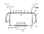
一方、エアバッグ装置12は、エアバッグモジュールとも呼ばれ、ステアリングホイール本体11のボス部15の正面側を覆うように配置されるもので、図3に示すように、合成樹脂、あるいは金属板などからなる被取付部材としてのベースプレート21、袋状のエアバッグ22、ガスを噴射するインフレータ23などを備えるとともに、樹脂製のカバー体24を備えている。そして、ベースプレート21は、ホーンプレートあるいはブラケット部などを介してステアリングホイール本体11(図5)に取り付けられ、このベースプレート21に、エアバッグ22、インフレータ23、及びカバー体24が取り付けられ、小さく折り畳まれたエアバッグ22がカバー体24により覆われている。   On the other hand, the airbag device 12 is also referred to as an airbag module, and is disposed so as to cover the front side of the boss portion 15 of the steering wheel main body 11. As shown in FIG. 3, a synthetic resin, a metal plate, or the like is used. A base plate 21 as a member to be attached, a bag-like airbag 22, an inflator 23 for injecting gas, and the like, and a resin cover body 24 are provided. The base plate 21 is attached to the steering wheel main body 11 (FIG. 5) via a horn plate or a bracket portion, and the airbag 22, the inflator 23, and the cover body 24 are attached to the base plate 21 and folded small. The airbag 22 is covered with a cover body 24.

そして、カバー体24は、ケース体、パッド、あるいはモジュールカバーなどとも呼ばれるもので、例えば合成樹脂などの部材により一体に形成されたカバー本体26と、このカバー本体26を一体に覆う表皮体27とを備えている。   The cover body 24 is also referred to as a case body, a pad, or a module cover. For example, a cover body 26 formed integrally with a member such as a synthetic resin, and a skin body 27 that integrally covers the cover body 26 It has.

カバー本体26は、ボス部15及びスポーク部16(図5)の一部を覆う対向部としての表板部31と、この表板部31の背面(裏面)から正面視略角筒状などの筒状に突設された取付壁部としての周壁である周板部32とを備えている。そして、カバー体24の表板部31と周板部32とに囲まれた部分が、折り畳んだエアバッグ22を収納するエアバッグ収納部となっている。このエアバッグ収納部の正面側に臨む部分には、装飾部材としてのエンブレム33(図2)が備えられていてもよい。   The cover body 26 includes a front plate portion 31 as a facing portion that covers a part of the boss portion 15 and the spoke portion 16 (FIG. 5), and a substantially rectangular tube shape in front view from the back surface (back surface) of the front plate portion 31. And a peripheral plate portion 32 that is a peripheral wall as a mounting wall portion protruding in a cylindrical shape. A portion of the cover body 24 surrounded by the front plate portion 31 and the peripheral plate portion 32 is an airbag storage portion that stores the folded airbag 22. An emblem 33 (FIG. 2) as a decorative member may be provided in a portion facing the front side of the airbag storage portion.

表板部31は、意匠上種々の形状を採り得るものであるが、本実施の形態では、表板部31は、ほぼボス部15(図5)の形状に沿って、正面視で周板部32よりも若干大きく形成された本体部としての正面板部35と、この正面板部35の外縁部である上端部から延設されこの正面板部35の上端部から背面側(反乗員側)に向かって延びる延設部としての延出板部36とを一体に備えている。また、この表板部31の背面側、すなわち反乗員側には、破断部としてのテアライン37が設けられている。そして、この表板部31は、エアバッグ装置12の意匠面を構成している。   Although the front plate portion 31 can take various shapes in design, in the present embodiment, the front plate portion 31 is a circumferential plate in a front view substantially along the shape of the boss portion 15 (FIG. 5). A front plate portion 35 as a main body formed slightly larger than the portion 32 and an upper end portion which is an outer edge portion of the front plate portion 35, and is extended from the upper end portion of the front plate portion 35 to the rear side (anti-occupant side). ) And an extending plate portion 36 as an extending portion extending in the direction. Further, a tear line 37 as a fracture portion is provided on the back side of the front plate portion 31, that is, on the side opposite to the passenger. The front plate portion 31 constitutes the design surface of the airbag device 12.

正面板部35は、エアバッグ22の突出方向側である後側を覆うもので、図4(a)に示すように、例えば正面から見て上側から下側へと徐々に左右方向に幅狭となる五角形状などに形成されている。この正面板部35には、エンブレム33(図2)を取り付けるための孔部38が開口されていてもよい。   The front plate portion 35 covers the rear side that is the protruding direction side of the airbag 22, and as shown in FIG. 4A, for example, the width gradually decreases from the upper side to the lower side when viewed from the front side. It is formed in a pentagon shape. The front plate portion 35 may be provided with a hole 38 for attaching the emblem 33 (FIG. 2).

延出板部36は、図1に示すように、正面板部35の上部に連続し、例えば左右両側から中央部に向かって徐々に前方に突出するように形成され、先端部である後縁部が円弧状に湾曲されている。   As shown in FIG. 1, the extension plate portion 36 is continuous with the upper portion of the front plate portion 35, and is formed so as to gradually protrude forward from the left and right sides toward the center portion. The part is curved in an arc shape.

図3に示す周板部32は、ベースプレート21に対してカバー体24を取り付ける部分である。この周板部32は、正面板部35の背面側からエアバッグ22の突出方向と反対方向に向かって筒状(枠状)に突設されている。   The peripheral plate portion 32 shown in FIG. 3 is a portion for attaching the cover body 24 to the base plate 21. The peripheral plate portion 32 protrudes in a cylindrical shape (frame shape) from the back side of the front plate portion 35 toward the direction opposite to the protruding direction of the airbag 22.

また、図2に示すエンブレム33は、オーナメントなどとも呼ばれるもので、硬質または軟質の合成樹脂により任意の形状に成形され適宜塗装やメッキなどの処理が施されており、表板部31の正面板部35に一体的に固定されている。なお、このエンブレム33は必須の構成ではない。   The emblem 33 shown in FIG. 2 is also called an ornament or the like, and is molded into an arbitrary shape with a hard or soft synthetic resin and appropriately subjected to a treatment such as painting or plating. It is fixed integrally to the part 35. The emblem 33 is not an essential component.

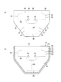
図4(a)に示すテアライン37は、テア、テア溝、開裂予定溝、扉予定線部などとも呼び得る薄肉部で、表板部31の正面板部35の背面(裏面)側を溝状に凹設し、表板部31の他の部分より脆弱で、破断可能及び変形容易な弱部として形成されている。そして、表板部31において、このテアライン37により外縁部が区画された部分が例えば複数の、本実施の形態では3つの扉予定部41となっているとともに、このテアライン37の外方、すなわち扉予定部41の周辺が非展開部である外郭部42となっている。また、このテアライン37は、設定したい扉予定部41の形状及び枚数に応じて任意に設定できるが、例えば本実施の形態では、正面板部35の両側の外縁部に沿う側部テアライン部45,45と、エンブレム33の下部に沿って側部テアライン部45,45間に連続する連結テアライン部46と、この連結テアライン部46の左右方向の略中央部であるエンブレム33の下方の位置から下方へと直線状に延出する延出テアライン部47と、この延出テアライン部47の下端部に連続して左右方向に延びる下部テアライン部48とを備えている。   The tear line 37 shown in FIG. 4 (a) is a thin-walled portion that can be called a tear, a tear groove, a planned cleavage groove, a planned door line portion, or the like, and the back surface (back surface) side of the front plate portion 35 of the front plate portion 31 is grooved. Is formed as a weak part that is more fragile than other parts of the front plate part 31 and that can be broken and easily deformed. In the front plate portion 31, the portion of which the outer edge portion is partitioned by the tear line 37 is, for example, a plurality of door planned portions 41 in the present embodiment, and the outside of the tear line 37, that is, the door A periphery of the planned portion 41 is an outer portion 42 that is a non-deployed portion. Further, the tear line 37 can be arbitrarily set according to the shape and number of the planned door portion 41 to be set.For example, in the present embodiment, the side tear line portions 45 along the outer edge portions on both sides of the front plate portion 35, 45, a connecting tear line portion 46 continuous between the side tear line portions 45, 45 along the lower portion of the emblem 33, and a position below the emblem 33, which is a substantially central portion in the left-right direction of the connecting tear line portion 46, downward. An extended tear line portion 47 extending linearly and a lower tear line portion 48 extending in the left-right direction continuously to the lower end portion of the extended tear line portion 47 are provided.

各扉予定部41は、通常時に折り畳んで収納されたエアバッグ22(図3)の膨出側を覆い、エアバッグ22(図3)の膨出時にはテアライン37から破断されて表板部31に扉部51(図3)を構成する部分である。各扉予定部41(扉部51(図3))は、エアバッグ22(図3)を所望の展開特性で展開させることができれば任意の形状とすることができるが、本実施の形態では、それぞれテアライン37により区画されて表板部31の上部に1つ、下部の左右両側に1つずつ、それぞれ形成されている。   Each door planned portion 41 covers the bulging side of the airbag 22 (FIG. 3) that is folded and stored in a normal state. When the airbag 22 (FIG. 3) bulges, it is broken from the tear line 37 to form the front plate portion 31. It is a part which comprises the door part 51 (FIG. 3). Each door planned portion 41 (door portion 51 (FIG. 3)) can be formed in any shape as long as the airbag 22 (FIG. 3) can be deployed with desired deployment characteristics. Each is partitioned by a tear line 37 and formed on the upper portion of the front plate portion 31 and on the left and right sides of the lower portion.

そして、側部テアライン部45,45の上端部間、及び、側部テアライン部45,45の下端部と下部テアライン部48の両端部との間が、それぞれ扉部51(図3)が正面側に展開する際の回動軸となるヒンジ部53,54,55となっている。すなわち、表板部31の外周部のテアライン37が形成されていない部分が、展開した扉部51(図3)を、非展開部である周板部32及び外郭部42に連接するようになっている。   And the door part 51 (FIG. 3) is a front side between the upper end part of the side part tear line part 45 and 45, and between the lower end part of the side part tear line part 45 and 45, and the both ends of the lower tear line part 48, respectively. Hinges 53, 54, and 55, which serve as pivot shafts when they are deployed in the same manner. That is, the portion of the outer peripheral portion of the front plate portion 31 where the tear line 37 is not formed connects the developed door portion 51 (FIG. 3) to the peripheral plate portion 32 and the outer portion 42 which are non-deployed portions. ing.

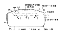
一方、図1に示す表皮体27は、カバー本体26の表面側を覆って外観や触感を向上するもので、天然皮革(本革)、人工皮革、あるいは軟質の樹脂などによりシート状に形成されている。本実施の形態では、表皮体27は、天然皮革により形成されている。また、この表皮体27は、カバー本体26の正面板部35の少なくとも一部、本実施の形態では全体を覆う表皮体本体部である表皮体正面部61と、カバー本体26の延出板部36の少なくとも一部、本実施の形態では全体を覆う表皮体延設部としての表皮体延出部62とを備えている。さらに、この表皮体27には、図2に示すように、表皮体正面部61の背面側、すなわち正面板部35に対向する前側に、テアライン37に沿って破断可能な破断予定部63が設けられている。また、この表皮体27には、図1に示すように、表皮体延出部62の背面側、すなわち延出板部36に対向する下側に、表皮体27の収縮応力を吸収する収縮応力吸収部としての薄肉部64が設けられている。この薄肉部64は、例えば表皮体27の厚みに対して半分以下の残厚で、所定幅となるようにレーザ加工などにより形成されている。そして、この表皮体27は、本実施の形態において、例えば一の表皮27aと他の表皮27bとに分割されている。これら一及び他の表皮27a,27bは、同じ材質のものでもよいし、互いに異なる材質のものでもよい。   On the other hand, the skin body 27 shown in FIG. 1 covers the surface side of the cover body 26 to improve the appearance and feel, and is formed into a sheet shape from natural leather (genuine leather), artificial leather, or soft resin. ing. In the present embodiment, the epidermis body 27 is formed of natural leather. Further, the skin body 27 includes at least a part of the front plate portion 35 of the cover body 26, and in this embodiment, the skin body front portion 61 which is the skin body portion covering the whole, and the extending plate portion of the cover body 26 In the present embodiment, at least a part of 36 is provided with an epidermis extending part 62 as an epidermis extending part covering the whole. Further, as shown in FIG. 2, the skin body 27 is provided with a planned fracture portion 63 that can be broken along the tear line 37 on the back side of the skin body front portion 61, that is, on the front side facing the front plate portion 35. It has been. Further, as shown in FIG. 1, the epidermis 27 has a contraction stress that absorbs the contraction stress of the epidermis 27 on the back side of the epidermis extension part 62, that is, on the lower side facing the extension plate part 36. A thin portion 64 as an absorbing portion is provided. The thin portion 64 is formed by laser processing or the like so as to have a predetermined width with a remaining thickness of less than half of the thickness of the epidermis 27, for example. In this embodiment, the epidermis 27 is divided into, for example, one epidermis 27a and another epidermis 27b. These one and other skins 27a and 27b may be made of the same material or different materials.

図2に示す表皮体正面部61は、カバー本体26の正面板部35と略同形状、すなわち例えば正面から見て上側から下側へと徐々に左右方向に幅狭となる五角形状などに形成されている。この表皮体正面部61には、エンブレム33を取り付けるための表皮体孔部65(図4(b))がカバー本体26の孔部38(図4(a))に対応する位置に設けられていてもよい。   The skin body front part 61 shown in FIG. 2 is formed in substantially the same shape as the front plate part 35 of the cover body 26, that is, for example, a pentagonal shape gradually narrowing in the left-right direction from the upper side to the lower side when viewed from the front. Has been. In the front surface portion 61 of the skin body, a skin body hole portion 65 (FIG. 4B) for attaching the emblem 33 is provided at a position corresponding to the hole portion 38 (FIG. 4A) of the cover body 26. May be.

図1に示す表皮体延出部62は、カバー本体26の延出板部36と略同形状、すなわち例えば左右両側から中央部に向かって徐々に前方に突出するように形成され、先端部である後縁部が円弧状に湾曲されている。   The skin extension portion 62 shown in FIG. 1 has substantially the same shape as the extension plate portion 36 of the cover body 26, that is, for example, is formed so as to gradually protrude forward from the left and right sides toward the center portion. A certain rear edge is curved in an arc shape.

図2に示す破断予定部63は、例えば表皮体27の厚みに対して半分以下の残厚となるように形成された凹部(薄肉部)であり、表皮体27の表皮体正面部61の他の部分より脆弱で、破断可能及び変形容易な弱部として形成されている。この破断予定部63は、例えばテアライン37(図4(a))と略等しい形状に形成されている。したがって、この破断予定部63は、例えば本実施の形態では、表皮体正面部61の外周部から延出板部36に亘って両側部に形成された両側の側部破断予定部66,66と、エンブレム33の下部に沿って側部破断予定部66,66間に連続する連結破断予定部67と、この連結破断予定部67の左右方向の略中央部であるエンブレム33の下方の位置から下方へと直線状に延出する延出破断予定部68と、この延出破断予定部68の下端部に連続して左右方向に延びる下部破断予定部69とを備えている。そして、これら側部破断予定部66,66が側部テアライン部45,45の前方に位置し、連結破断予定部67が連結テアライン部46の前方に位置し、延出破断予定部68が延出テアライン部47の前方に位置し、下部破断予定部69が下部テアライン部48の前方に位置する。   2 is a concave portion (thin wall portion) formed so as to have a remaining thickness that is less than half of the thickness of the epidermis 27, and other than the epidermis front portion 61 of the epidermis 27. It is formed as a weak part that is more fragile than the part and can be broken and easily deformed. The planned fracture portion 63 is formed in a shape substantially equal to the tear line 37 (FIG. 4A), for example. Therefore, for example, in the present embodiment, the planned fracture portion 63 includes both side fracture planned portions 66, 66 formed on both sides from the outer peripheral portion of the skin body front portion 61 to the extending plate portion 36. The connection breakage planned portion 67 that continues between the side breakage planned portions 66, 66 along the lower part of the emblem 33, and the position below the emblem 33 that is a substantially central portion in the left-right direction of the connection breakage planned portion 67. An extended fracture planned portion 68 that extends linearly to the left and a lower fracture planned portion 69 that extends in the left-right direction continuously to the lower end of the extended fracture planned portion 68 are provided. These side portion planned break portions 66 and 66 are located in front of the side tear line portions 45 and 45, the connection break planned portion 67 is located in front of the connection tear line portion 46, and the extended break planned portion 68 extends. The lower fracture scheduled portion 69 is located in front of the lower tear line portion 48 and is located in front of the tear line portion 47.

図1に示す薄肉部64は、例えば表皮体27の厚みに対して半分以下の残厚となるように形成された、細長い線状の凹部である。この薄肉部64は、図2に示す破断予定部63(テアライン37)と異なる位置、すなわち破断予定部63(テアライン37)に対して離間された位置に配置されている。また、図1に戻って、この薄肉部64は、左右方向、すなわち表皮体延出部62から表皮体正面部61に向かう方向(前後方向)に対して交差(直交)する方向に沿って断続的(破線状)に形成されている。さらに、この薄肉部64は、前後方向、すなわち表皮体延出部62から表皮体正面部61に向かう方向に複数列配置されている。本実施の形態では、この薄肉部64は、3列配置されており、最前列、すなわち表皮体正面部61に対して最も遠い第1列64aが、表皮体延出部62(延出板部36)の後縁部に沿って略円弧状に断続的に配置され、この第1列64aの前方(表皮体正面部61寄り)に離間されて位置する第2列64bが、左右方向に沿って直線状に断続的に配置され、この第2列64bの前方(表皮体正面部61寄り)に離間されて位置する最後列、すなわち表皮体正面部61に対して最も近い第3列64cが、左右方向に沿って直線状に、すなわち第2列64bと略平行に断続的に配置されている。したがって、この薄肉部64は、表皮体延出部62(延出板部36)の輪郭に対して平行な方向または交差する方向に沿って形成されている。また、薄肉部64は、互いに隣り合う列同士、すなわち第1列64aと第2列64b、及び、第2列64bと第3列64cが、それぞれ左右に互い違いにずれるように配置されている。そして、この薄肉部64は、全体として、表皮体延出部62の前後方向の中央部よりも前側寄り、すなわち表皮体正面部61から離間された領域に配置されている。   The thin-walled portion 64 shown in FIG. 1 is an elongated linear concave portion that is formed so as to have a remaining thickness that is less than half of the thickness of the epidermis 27, for example. The thin-walled portion 64 is disposed at a position different from the planned fracture portion 63 (the tear line 37) shown in FIG. 2, that is, a position separated from the planned fracture portion 63 (the tear line 37). Returning to FIG. 1, the thin-walled portion 64 is intermittent along the direction intersecting (orthogonal) with respect to the left-right direction, that is, the direction (front-rear direction) from the epidermis extending portion 62 toward the epidermis front portion 61. It is formed like a broken line. Further, the thin-walled portions 64 are arranged in a plurality of rows in the front-rear direction, that is, in the direction from the epidermis extending portion 62 to the epidermis front portion 61. In the present embodiment, the thin portions 64 are arranged in three rows, and the front row, that is, the first row 64a farthest from the skin front portion 61 is the skin extension portion 62 (extension plate portion). 36) A second row 64b that is intermittently arranged in a substantially arc shape along the rear edge of the first row 64a and is separated from the front of the first row 64a (closer to the frontal body front portion 61) extends along the left-right direction. The third row 64c that is intermittently arranged in a straight line and is spaced apart in front of the second row 64b (near the skin front portion 61), that is, the third row 64c closest to the skin front portion 61 is These are arranged intermittently in a straight line along the left-right direction, that is, substantially in parallel with the second row 64b. Therefore, the thin portion 64 is formed along a direction parallel to or intersecting with the contour of the epidermis extending portion 62 (extending plate portion 36). Further, the thin portion 64 is arranged so that the columns adjacent to each other, that is, the first column 64a and the second column 64b, and the second column 64b and the third column 64c are alternately shifted to the left and right. The thin-walled portion 64 as a whole is disposed closer to the front side than the central portion in the front-rear direction of the epidermis extending portion 62, that is, in a region separated from the epidermis front portion 61.

また、一の表皮27aは、表板部31の主意匠を構成するもので、図2に示すように、例えば左右両側から下方に向かって徐々に幅狭となる五角形状に形成されている。この一の表皮27aは、表皮体正面部61及び表皮体延出部62の大部分(中央部)を構成するものであり、表板部31において、正面板部35及び延出板部36(図1)の中央部の所定幅の表面を覆っている。したがって、この一の表皮27aは、テアライン37(側部テアライン部45,45、連結テアライン部46、延出テアライン部47及び下部テアライン部48)をそれぞれ覆っている。また、一の表皮27aの外縁部は、他の表皮27bに対して重ねられて接合される重ね部71となっている。この重ね部71は、一の表皮27aの背面側に折り返されて巻き込まれた巻き込み部であり、他の表皮27bに対して、ステッチ部72により縫製されて接合されている。このステッチ部72は、一の表皮27aの上部、両側部及び下部に亘って設けられ、両側部が上下方向に沿い、表皮体27の表皮体正面部61と表皮体延出部62とに亘って連続している。さらに、一の表皮27aの背面側に、破断予定部63及び薄肉部64(図1)が位置している。   Further, one skin 27a constitutes the main design of the surface plate portion 31, and as shown in FIG. 2, for example, it is formed in a pentagonal shape that gradually becomes narrower from the left and right sides downward. This one skin 27a constitutes most (central part) of the skin body front part 61 and the skin body extension part 62. In the surface board part 31, the front panel part 35 and the extension board part 36 ( It covers the surface of a predetermined width at the center of FIG. Accordingly, the one skin 27a covers the tear lines 37 (side tear line portions 45, 45, connecting tear line portions 46, extended tear line portions 47, and lower tear line portions 48). The outer edge portion of one skin 27a is an overlapping portion 71 that is overlapped and joined to the other skin 27b. The overlapping portion 71 is a winding portion that is folded and wound around the back side of one skin 27a, and is stitched and joined to the other skin 27b by a stitch portion 72. This stitch portion 72 is provided over the upper portion, both side portions, and the lower portion of one skin 27a, and both side portions extend in the vertical direction, and spans the epidermis front portion 61 and the epidermis extending portion 62 of the epidermis 27. Are continuous. Furthermore, the fracture | rupture planned part 63 and the thin part 64 (FIG. 1) are located in the back side of the one skin 27a.

他の表皮27bは、一の表皮27aの両側部及び下部を囲んで形成されている。他の表皮27bは、表板部31において、正面板部35の両側部ないし下部と、延出板部36(図1)の両側部との表面を覆っている。このため、他の表皮27bは、テアライン37の外方に位置している。   The other skin 27b is formed so as to surround both sides and the lower part of one skin 27a. The other skin 27b covers the surface of the front plate portion 31 on both sides or the lower portion of the front plate portion 35 and both sides of the extended plate portion 36 (FIG. 1). For this reason, the other epidermis 27b is located outside the tear line 37.

そして、カバー体24の製造の際には、図3に示す表板部31及び周板部32を備えるカバー本体26を予め合成樹脂により射出成形する。このとき、図1に示す表皮体27(一及び他の表皮27a,27b)は、カバー本体26に対して一体的にインサート成形してもよいし、別途成形したカバー本体26に後工程で貼り付けてもよい。そして、表皮体27(一及び他の表皮27a,27b)により表板部31を覆ったカバー体24に対して、別途成形したエンブレム33(図2)を取り付ける。   When the cover body 24 is manufactured, the cover body 26 including the front plate portion 31 and the peripheral plate portion 32 shown in FIG. 3 is injection-molded with a synthetic resin in advance. At this time, the skin 27 (one and other skins 27a and 27b) shown in FIG. 1 may be insert-molded integrally with the cover body 26, or may be pasted on the separately formed cover body 26 in a later step. May be attached. Then, a separately molded emblem 33 (FIG. 2) is attached to the cover body 24 that covers the surface plate portion 31 with the skin body 27 (one and other skins 27a and 27b).

このカバー体24を備えたエアバッグ装置12をステアリングホイール10(図5)に備えた自動車が衝突などすると、制御装置が図3に示すインフレータ23を作動させ、エアバッグ22にガスを供給する。すると、エアバッグ22が急速に膨張展開し、この膨張展開する圧力が各扉予定部41を押し上げ、テアライン37にエアバッグ22の膨張圧力が作用して、このテアライン37に沿ってカバー体24の表板部31が破断予定部63から開裂する表皮体27と一体的に破断し、扉部51を形成する。そして、形成された扉部51は、ヒンジ部53,54,55(図4(a))を軸として回動してエアバッグ22を膨出させる開口である突出口74を形成し、この突出口74からエアバッグ22が乗員の前方に展開し、乗員を保護する。   When an automobile equipped with the airbag device 12 having the cover body 24 on the steering wheel 10 (FIG. 5) collides, the control device activates the inflator 23 shown in FIG. 3 to supply gas to the airbag 22. Then, the airbag 22 is rapidly inflated and deployed, and the pressure for inflating and deploying pushes up each door planned portion 41, and the inflation pressure of the airbag 22 acts on the tear line 37, and the cover body 24 moves along the tear line 37. The front plate portion 31 is integrally broken with the skin body 27 that is torn from the planned fracture portion 63 to form a door portion 51. The formed door 51 forms a projecting opening 74 that is an opening that rotates around the hinges 53, 54, and 55 (FIG. 4A) to inflate the airbag 22. The airbag 22 is deployed in front of the occupant from the mouth 74 to protect the occupant.

ここで、例えば夏の炎天下などに自動車を駐車したときなどには、エアバッグ装置12のカバー体24が加熱され、カバー本体26の意匠面に貼り付けられた表皮体27が熱によって縮むように、表皮体27の中央部、すなわち図2に示す表皮体正面部61の中央部(エンブレム33)に向かって(矢印D方向に向かって)応力が発生する。換言すれば、図1に示すように、カバー本体26の延出板部36を覆う表皮体27の表皮体延出部62は、表皮体正面部61に引き寄せられるように前方かつ左右方向の中央部に向かって(矢印D方向に向かって)応力が発生する。   Here, for example, when a car is parked, for example, under a hot summer sun, the cover body 24 of the airbag device 12 is heated, and the epidermis body 27 attached to the design surface of the cover body 26 is shrunk by heat. Stress is generated toward the center portion of the skin body 27, that is, the center portion (emblem 33) of the skin body front portion 61 shown in FIG. 2 (in the direction of arrow D). In other words, as shown in FIG. 1, the epidermis extending portion 62 of the epidermis 27 covering the extending plate portion 36 of the cover body 26 is centered in the front and left and right directions so as to be drawn toward the epidermis front portion 61. Stress is generated toward the part (in the direction of arrow D).

そこで、本実施の形態では、表皮体27にて、カバー本体26の延出板部36に対向する位置である表皮体延出部62に、収縮応力を吸収する薄肉部64を設けたので、加熱などによる上記の表皮体27の中央部に向かう収縮応力により薄肉部64によって表皮体27(表皮体延出部62)が延び、収縮応力を効果的に吸収して緩和できる。したがって、高温下となる車室内にエアバッグ装置12のカバー体24が置かれても、この収縮応力に起因するカバー本体26の商品性を損なうような変形及び表皮体27の端末部などのカバー本体26からの剥がれを防止できる。   Therefore, in the present embodiment, in the skin body 27, the thin body portion 64 that absorbs the contraction stress is provided in the skin body extension portion 62 that is a position facing the extension plate portion 36 of the cover body 26. The skin 27 (skin extension 62) is extended by the thin-walled portion 64 due to the shrinkage stress toward the center of the skin 27 due to heating or the like, and the contraction stress can be effectively absorbed and relaxed. Therefore, even if the cover body 24 of the airbag device 12 is placed in a vehicle compartment that is at a high temperature, the cover body 26 is deformed so as to impair the merchantability of the cover body 26 due to the contraction stress, and the cover of the terminal portion of the skin body 27, etc. The peeling from the main body 26 can be prevented.

また、薄肉部64を、カバー本体26に設けたテアライン37に沿って破断可能な破断予定部63に対して離間して設けたので、エアバッグ22の展開時のカバー本体26のテアライン37からの破断及び表皮体27の破断予定部63からの破断を薄肉部64により妨げることがない。   Further, since the thin-walled portion 64 is provided apart from the breakable portion 63 that can be broken along the tear line 37 provided in the cover body 26, the thin-walled portion 64 from the tear line 37 of the cover body 26 when the airbag 22 is deployed. The thin portion 64 does not prevent the breakage and the breakage of the epidermis 27 from the planned breakage portion 63.

さらに、薄肉部64を、延出板部36の輪郭に対して平行な方向と交差する方向とのいずれかの方向に沿って形成したので、薄肉部64が表皮体27の収縮方向(矢印D方向)に対向して配置され、表皮体27に生じる収縮応力を最も効果的に吸収できる位置となるため、この収縮応力に起因するカバー本体26の商品性を損なうような変形及び表皮体27の端末部などのカバー本体26からの剥がれを、より効果的に防止できる。   Furthermore, since the thin wall portion 64 is formed along one of the direction parallel to the direction parallel to the contour of the extending plate portion 36 and the direction intersecting the thin plate portion 64, the thin wall portion 64 is contracted in the direction of contraction of the epidermis 27 (arrow D). And the position where the contraction stress generated in the epidermis 27 can be absorbed most effectively. Peeling from the cover body 26 such as the terminal portion can be more effectively prevented.

また、薄肉部64は、意匠面の外観性能を損なうことがないとともに、破断予定部63と同時に加工できるので、製造コストの低減が図れる。   In addition, the thin-walled portion 64 does not impair the appearance performance of the design surface and can be processed simultaneously with the planned fracture portion 63, so that the manufacturing cost can be reduced.

特に、皮革の中でも、天然皮革が熱による収縮応力が最も大きいとされるが、上記の薄肉部64により、表皮体27として天然皮革を用いた、高級感のあるカバー体24としつつ、表皮体27の収縮応力に起因するカバー本体26の変形及び表皮体27の端末部などのカバー本体26からの剥がれを確実に防止できる。   In particular, among leather, natural leather is said to have the largest shrinkage stress due to heat, but with the thin-walled portion 64 described above, the skin body is made of natural leather as the skin body 27, making it a high-quality cover body 24. It is possible to reliably prevent the deformation of the cover main body 26 due to the contraction stress 27 and the peeling of the end portion of the skin body 27 from the cover main body 26.

なお、上記の第1の実施の形態の薄肉部64としては、例えば図6に示す第2の実施の形態のように、左右方向に連続し前後方向に交互に湾曲する波状の複数列に形成してもよいし、図7に示す第3の実施の形態のように、左右方向に連続し前後方向に交互にジグザグ状(三角波状)に折れ曲がる折れ線状の複数列に形成してもよい。   The thin portion 64 of the first embodiment is formed in a plurality of wavy rows that are continuous in the left-right direction and alternately curved in the front-rear direction, for example, as in the second embodiment shown in FIG. Alternatively, as in the third embodiment shown in FIG. 7, it may be formed in a plurality of lines of polygonal lines that are continuous in the left-right direction and are alternately bent in a zigzag shape (triangular wave shape) in the front-rear direction.

また、上記各実施の形態において、収縮応力吸収部として薄肉部64を例示したが、これに限定されるものではない。例えば、表皮体27の表皮体延出部62の背面側に、この表皮体27の厚みに対して半分以下の残厚となるように設定した複数列の加工刃や格子状の加工刃を備えた治具に対して表皮体延出部62を押圧する押圧加工により例えば采の目状の切込みを入れてもよいし、皮革産業のなめしに使用されるなめし剤やミンクオイルなどを表皮体延出部62の背面側の所定位置に塗布し、化学的に収縮応力吸収部を形成してもよい。   In each of the above embodiments, the thin portion 64 is exemplified as the contraction stress absorbing portion, but the present invention is not limited to this. For example, on the back side of the epidermis extending portion 62 of the epidermis 27, a plurality of rows of processing blades and grid-like processing blades set so that the remaining thickness is less than half the thickness of the epidermis 27 For example, an eye cut may be made by pressing the epidermis extending portion 62 against a jig, or a tanning agent or mink oil used for tanning in the leather industry may be applied. It may be applied to a predetermined position on the back side of the protruding portion 62 to chemically form a contraction stress absorbing portion.

また、上記各実施の形態において、カバー体24は、運転席用のエアバッグ装置だけでなく、例えばインストルメントパネル部に設置されて助手席の乗員の前方にエアバッグを展開する助手席用のエアバッグ装置、あるいは助手席の乗員に対向する縦壁面部と乗員の下肢部との間にエアバッグを展開するニーエアバッグ装置などにも適用できる。   Further, in each of the above embodiments, the cover body 24 is not only used for the driver's seat airbag device, but also installed for example in the instrument panel section and used for the passenger seat that deploys the airbag in front of the passenger in the passenger seat. The present invention can also be applied to an airbag device or a knee airbag device that deploys an airbag between a vertical wall surface portion facing a passenger in a passenger seat and a lower limb portion of the passenger.

本発明は、例えば運転席用のエアバッグ装置のカバー体として好適に用いることができる。   The present invention can be suitably used as a cover body of an airbag device for a driver's seat, for example.

12 エアバッグ装置
22 エアバッグ
24 カバー体
26 カバー本体
27 表皮体
35 本体部としての正面板部
36 延設部としての延出板部
37 テアライン
51 扉部
63 破断予定部
64 収縮応力吸収部としての薄肉部
12 Airbag device
22 airbag
24 Cover body
26 Cover body
27 epidermis
35 Front plate as main unit
36 Extension plate as extension
37 Tearline
51 Door
63 Planned break
64 Thin part as shrinkage stress absorbing part

Claims (5)

カバー本体と、
このカバー本体の意匠面の少なくとも一部を覆って配置された表皮体とを具備し、
前記カバー本体は、
収納されたエアバッグを覆う本体部と、
この本体部の外縁部に延設され、この本体部とともに前記意匠面の少なくとも一部を構成する延設部とを備え、
前記表皮体は、前記延設部に対向する位置に設けられ、収縮応力を吸収する収縮応力吸収部を備えた
ことを特徴とするエアバッグ装置のカバー体。
A cover body;
The cover body arranged to cover at least a part of the design surface of the cover body,
The cover body is
A main body that covers the stored airbag;
Extending to the outer edge portion of the main body portion, and including an extending portion constituting at least part of the design surface together with the main body portion,
The cover body of the airbag device, wherein the skin body includes a contraction stress absorbing portion that is provided at a position facing the extension portion and absorbs contraction stress.
カバー本体は、本体部のエアバッグに対向する側に設けられ、前記エアバッグの膨張展開時に開裂して複数の扉部を形成するテアラインを備え、
表皮体は、前記テアラインに沿って破断可能な破断予定部を備え、
収縮応力吸収部は、前記破断予定部に対して離間された位置に設けられた
ことを特徴とする請求項1記載のエアバッグ装置のカバー体。
The cover body is provided on the side of the body portion facing the airbag, and includes a tear line that is cleaved when the airbag is inflated and deployed to form a plurality of door portions,
The epidermis has a breakable portion that can break along the tear line,
The cover body of an airbag device according to claim 1, wherein the shrinkage stress absorbing portion is provided at a position spaced apart from the planned breaking portion.
収縮応力吸収部は、延設部の輪郭に対して平行な方向と交差する方向とのいずれかの方向に沿って設けられている
ことを特徴とする請求項1または2記載のエアバッグ装置のカバー体。
3. The airbag device according to claim 1, wherein the shrinkage stress absorbing portion is provided along one of a direction parallel to and a direction crossing the outline of the extending portion. Cover body.
収縮応力吸収部は、薄肉部である
ことを特徴とする請求項1ないし3いずれか一記載のエアバッグ装置のカバー体。
The cover body of an airbag device according to any one of claims 1 to 3, wherein the shrinkage stress absorbing portion is a thin portion.
表皮体は、天然皮革により構成されている
ことを特徴とする請求項1ないし4いずれか一記載のエアバッグ装置のカバー体。
The cover body of the airbag device according to any one of claims 1 to 4, wherein the skin body is made of natural leather.
JP2015251325A 2015-12-24 2015-12-24 Cover body for air bag device Pending JP2017114262A (en)

Priority Applications (1)

Application Number Priority Date Filing Date Title
JP2015251325A JP2017114262A (en) 2015-12-24 2015-12-24 Cover body for air bag device

Applications Claiming Priority (1)

Application Number Priority Date Filing Date Title
JP2015251325A JP2017114262A (en) 2015-12-24 2015-12-24 Cover body for air bag device

Publications (1)

Publication Number Publication Date
JP2017114262A true JP2017114262A (en) 2017-06-29

Family

ID=59233298

Family Applications (1)

Application Number Title Priority Date Filing Date
JP2015251325A Pending JP2017114262A (en) 2015-12-24 2015-12-24 Cover body for air bag device

Country Status (1)

Country Link
JP (1) JP2017114262A (en)

Cited By (1)

* Cited by examiner, † Cited by third party
Publication number Priority date Publication date Assignee Title
DE112018001877T5 (en) 2017-04-07 2019-12-19 Semiconductor Energy Laboratory Co., Ltd. Light emitting element, display device, electronic device and lighting device

Cited By (1)

* Cited by examiner, † Cited by third party
Publication number Priority date Publication date Assignee Title
DE112018001877T5 (en) 2017-04-07 2019-12-19 Semiconductor Energy Laboratory Co., Ltd. Light emitting element, display device, electronic device and lighting device

Similar Documents

Publication Publication Date Title
JP6026249B2 (en) Cover body of airbag device
US7631892B2 (en) Airbag, airbag folding method, and airbag device
JP4005023B2 (en) Interior paneling parts for automobiles
JP6727099B2 (en) Cover body of airbag device
KR0121320B1 (en) Module cover of air bag
JP2006001326A (en) Airbag cover and airbag device
JP5506630B2 (en) Cover body of airbag device
JP2007076393A (en) Vehicular interior device provided with airbag door part
JP6628408B2 (en) Cover body of airbag device
US20090236831A1 (en) Airbag cover and airbag device
JP2017114262A (en) Cover body for air bag device
JP5014173B2 (en) Cover body of airbag device and airbag device
JP2538159B2 (en) Airbag cover body
JP2004155212A (en) Interior member for vehicle having air bag door section
JP3304693B2 (en) Manufacturing method of airbag cover
JP5080216B2 (en) Steering device, steering wheel
JP2005289250A (en) Interior trim component for automobile
KR20060092659A (en) Structure of airbag door for passanger of a car
US20120074675A1 (en) Cover for airbag apparatus
JP6706966B2 (en) Cover body of airbag device
JP2013123974A (en) Module cover and airbag device
JP2000238602A (en) Manufacture of lid for air bag device
JP3909766B2 (en) Airbag device
JPH05170044A (en) Air bag cover body
JPH11105657A (en) Air bag device-integrated steering wheel