EP3928089B1 - Verfahren und system zur überwachung einer glukosekonzentration unter verwendung von harmonischen beziehungen - Google Patents
Verfahren und system zur überwachung einer glukosekonzentration unter verwendung von harmonischen beziehungen Download PDFInfo
- Publication number
- EP3928089B1 EP3928089B1 EP20707381.8A EP20707381A EP3928089B1 EP 3928089 B1 EP3928089 B1 EP 3928089B1 EP 20707381 A EP20707381 A EP 20707381A EP 3928089 B1 EP3928089 B1 EP 3928089B1
- Authority
- EP
- European Patent Office
- Prior art keywords
- harmonic
- analyte
- circuit
- containing fluid
- signal
- Prior art date
- Legal status (The legal status is an assumption and is not a legal conclusion. Google has not performed a legal analysis and makes no representation as to the accuracy of the status listed.)
- Active
Links
Images



Classifications
-
- G—PHYSICS
- G01—MEASURING; TESTING
- G01N—INVESTIGATING OR ANALYSING MATERIALS BY DETERMINING THEIR CHEMICAL OR PHYSICAL PROPERTIES
- G01N27/00—Investigating or analysing materials by the use of electric, electrochemical, or magnetic means
- G01N27/26—Investigating or analysing materials by the use of electric, electrochemical, or magnetic means by investigating electrochemical variables; by using electrolysis or electrophoresis
- G01N27/28—Electrolytic cell components
- G01N27/30—Electrodes, e.g. test electrodes; Half-cells
- G01N27/327—Biochemical electrodes, e.g. electrical or mechanical details for in vitro measurements
- G01N27/3271—Amperometric enzyme electrodes for analytes in body fluids, e.g. glucose in blood
- G01N27/3273—Devices therefor, e.g. test element readers, circuitry
-
- A—HUMAN NECESSITIES
- A61—MEDICAL OR VETERINARY SCIENCE; HYGIENE
- A61B—DIAGNOSIS; SURGERY; IDENTIFICATION
- A61B5/00—Measuring for diagnostic purposes; Identification of persons
- A61B5/0002—Remote monitoring of patients using telemetry, e.g. transmission of vital signals via a communication network
- A61B5/0015—Remote monitoring of patients using telemetry, e.g. transmission of vital signals via a communication network characterised by features of the telemetry system
- A61B5/002—Monitoring the patient using a local or closed circuit, e.g. in a room or building
-
- A—HUMAN NECESSITIES
- A61—MEDICAL OR VETERINARY SCIENCE; HYGIENE
- A61B—DIAGNOSIS; SURGERY; IDENTIFICATION
- A61B5/00—Measuring for diagnostic purposes; Identification of persons
- A61B5/05—Detecting, measuring or recording for diagnosis by means of electric currents or magnetic fields; Measuring using microwaves or radio waves
- A61B5/053—Measuring electrical impedance or conductance of a portion of the body
- A61B5/0537—Measuring body composition by impedance, e.g. tissue hydration or fat content
-
- A—HUMAN NECESSITIES
- A61—MEDICAL OR VETERINARY SCIENCE; HYGIENE
- A61B—DIAGNOSIS; SURGERY; IDENTIFICATION
- A61B5/00—Measuring for diagnostic purposes; Identification of persons
- A61B5/145—Measuring characteristics of blood in vivo, e.g. gas concentration or pH-value ; Measuring characteristics of body fluids or tissues, e.g. interstitial fluid or cerebral tissue
- A61B5/14507—Measuring characteristics of blood in vivo, e.g. gas concentration or pH-value ; Measuring characteristics of body fluids or tissues, e.g. interstitial fluid or cerebral tissue specially adapted for measuring characteristics of body fluids other than blood
- A61B5/1451—Measuring characteristics of blood in vivo, e.g. gas concentration or pH-value ; Measuring characteristics of body fluids or tissues, e.g. interstitial fluid or cerebral tissue specially adapted for measuring characteristics of body fluids other than blood for interstitial fluid
-
- A—HUMAN NECESSITIES
- A61—MEDICAL OR VETERINARY SCIENCE; HYGIENE
- A61B—DIAGNOSIS; SURGERY; IDENTIFICATION
- A61B5/00—Measuring for diagnostic purposes; Identification of persons
- A61B5/145—Measuring characteristics of blood in vivo, e.g. gas concentration or pH-value ; Measuring characteristics of body fluids or tissues, e.g. interstitial fluid or cerebral tissue
- A61B5/14532—Measuring characteristics of blood in vivo, e.g. gas concentration or pH-value ; Measuring characteristics of body fluids or tissues, e.g. interstitial fluid or cerebral tissue for measuring glucose, e.g. by tissue impedance measurement
-
- A—HUMAN NECESSITIES
- A61—MEDICAL OR VETERINARY SCIENCE; HYGIENE
- A61B—DIAGNOSIS; SURGERY; IDENTIFICATION
- A61B5/00—Measuring for diagnostic purposes; Identification of persons
- A61B5/145—Measuring characteristics of blood in vivo, e.g. gas concentration or pH-value ; Measuring characteristics of body fluids or tissues, e.g. interstitial fluid or cerebral tissue
- A61B5/1468—Measuring characteristics of blood in vivo, e.g. gas concentration or pH-value ; Measuring characteristics of body fluids or tissues, e.g. interstitial fluid or cerebral tissue using chemical or electrochemical methods, e.g. by polarographic means
- A61B5/1473—Measuring characteristics of blood in vivo, e.g. gas concentration or pH-value ; Measuring characteristics of body fluids or tissues, e.g. interstitial fluid or cerebral tissue using chemical or electrochemical methods, e.g. by polarographic means invasive, e.g. introduced into the body by a catheter
-
- A—HUMAN NECESSITIES
- A61—MEDICAL OR VETERINARY SCIENCE; HYGIENE
- A61B—DIAGNOSIS; SURGERY; IDENTIFICATION
- A61B5/00—Measuring for diagnostic purposes; Identification of persons
- A61B5/145—Measuring characteristics of blood in vivo, e.g. gas concentration or pH-value ; Measuring characteristics of body fluids or tissues, e.g. interstitial fluid or cerebral tissue
- A61B5/1468—Measuring characteristics of blood in vivo, e.g. gas concentration or pH-value ; Measuring characteristics of body fluids or tissues, e.g. interstitial fluid or cerebral tissue using chemical or electrochemical methods, e.g. by polarographic means
- A61B5/1477—Measuring characteristics of blood in vivo, e.g. gas concentration or pH-value ; Measuring characteristics of body fluids or tissues, e.g. interstitial fluid or cerebral tissue using chemical or electrochemical methods, e.g. by polarographic means non-invasive
-
- A—HUMAN NECESSITIES
- A61—MEDICAL OR VETERINARY SCIENCE; HYGIENE
- A61B—DIAGNOSIS; SURGERY; IDENTIFICATION
- A61B5/00—Measuring for diagnostic purposes; Identification of persons
- A61B5/68—Arrangements of detecting, measuring or recording means, e.g. sensors, in relation to patient
- A61B5/6846—Arrangements of detecting, measuring or recording means, e.g. sensors, in relation to patient specially adapted to be brought in contact with an internal body part, i.e. invasive
- A61B5/6847—Arrangements of detecting, measuring or recording means, e.g. sensors, in relation to patient specially adapted to be brought in contact with an internal body part, i.e. invasive mounted on an invasive device
-
- A—HUMAN NECESSITIES
- A61—MEDICAL OR VETERINARY SCIENCE; HYGIENE
- A61B—DIAGNOSIS; SURGERY; IDENTIFICATION
- A61B5/00—Measuring for diagnostic purposes; Identification of persons
- A61B5/72—Signal processing specially adapted for physiological signals or for diagnostic purposes
- A61B5/7203—Signal processing specially adapted for physiological signals or for diagnostic purposes for noise prevention, reduction or removal
- A61B5/7207—Signal processing specially adapted for physiological signals or for diagnostic purposes for noise prevention, reduction or removal of noise induced by motion artifacts
-
- A—HUMAN NECESSITIES
- A61—MEDICAL OR VETERINARY SCIENCE; HYGIENE
- A61B—DIAGNOSIS; SURGERY; IDENTIFICATION
- A61B5/00—Measuring for diagnostic purposes; Identification of persons
- A61B5/72—Signal processing specially adapted for physiological signals or for diagnostic purposes
- A61B5/7225—Details of analogue processing, e.g. isolation amplifier, gain or sensitivity adjustment, filtering, baseline or drift compensation
-
- A—HUMAN NECESSITIES
- A61—MEDICAL OR VETERINARY SCIENCE; HYGIENE
- A61B—DIAGNOSIS; SURGERY; IDENTIFICATION
- A61B5/00—Measuring for diagnostic purposes; Identification of persons
- A61B5/72—Signal processing specially adapted for physiological signals or for diagnostic purposes
- A61B5/7235—Details of waveform analysis
- A61B5/7253—Details of waveform analysis characterised by using transforms
- A61B5/7257—Details of waveform analysis characterised by using transforms using Fourier transforms
-
- A—HUMAN NECESSITIES
- A61—MEDICAL OR VETERINARY SCIENCE; HYGIENE
- A61B—DIAGNOSIS; SURGERY; IDENTIFICATION
- A61B5/00—Measuring for diagnostic purposes; Identification of persons
- A61B5/74—Details of notification to user or communication with user or patient; User input means
- A61B5/742—Details of notification to user or communication with user or patient; User input means using visual displays
-
- G—PHYSICS
- G01—MEASURING; TESTING
- G01N—INVESTIGATING OR ANALYSING MATERIALS BY DETERMINING THEIR CHEMICAL OR PHYSICAL PROPERTIES
- G01N27/00—Investigating or analysing materials by the use of electric, electrochemical, or magnetic means
- G01N27/26—Investigating or analysing materials by the use of electric, electrochemical, or magnetic means by investigating electrochemical variables; by using electrolysis or electrophoresis
- G01N27/28—Electrolytic cell components
- G01N27/30—Electrodes, e.g. test electrodes; Half-cells
- G01N27/327—Biochemical electrodes, e.g. electrical or mechanical details for in vitro measurements
- G01N27/3271—Amperometric enzyme electrodes for analytes in body fluids, e.g. glucose in blood
- G01N27/3274—Corrective measures, e.g. error detection, compensation for temperature or hematocrit, calibration
-
- G—PHYSICS
- G01—MEASURING; TESTING
- G01N—INVESTIGATING OR ANALYSING MATERIALS BY DETERMINING THEIR CHEMICAL OR PHYSICAL PROPERTIES
- G01N31/00—Investigating or analysing non-biological materials by the use of the chemical methods specified in the subgroup; Apparatus specially adapted for such methods
- G01N31/005—Investigating or analysing non-biological materials by the use of the chemical methods specified in the subgroup; Apparatus specially adapted for such methods investigating the presence of an element by oxidation
-
- G—PHYSICS
- G01—MEASURING; TESTING
- G01N—INVESTIGATING OR ANALYSING MATERIALS BY DETERMINING THEIR CHEMICAL OR PHYSICAL PROPERTIES
- G01N33/00—Investigating or analysing materials by specific methods not covered by groups G01N1/00 - G01N31/00
- G01N33/48—Biological material, e.g. blood, urine; Haemocytometers
- G01N33/50—Chemical analysis of biological material, e.g. blood, urine; Testing involving biospecific ligand binding methods; Immunological testing
- G01N33/66—Chemical analysis of biological material, e.g. blood, urine; Testing involving biospecific ligand binding methods; Immunological testing involving blood sugars, e.g. galactose
-
- G—PHYSICS
- G06—COMPUTING OR CALCULATING; COUNTING
- G06F—ELECTRIC DIGITAL DATA PROCESSING
- G06F1/00—Details not covered by groups G06F3/00 - G06F13/00 and G06F21/00
- G06F1/16—Constructional details or arrangements
- G06F1/1613—Constructional details or arrangements for portable computers
- G06F1/163—Wearable computers, e.g. on a belt
-
- G—PHYSICS
- G06—COMPUTING OR CALCULATING; COUNTING
- G06F—ELECTRIC DIGITAL DATA PROCESSING
- G06F17/00—Digital computing or data processing equipment or methods, specially adapted for specific functions
- G06F17/10—Complex mathematical operations
- G06F17/14—Fourier, Walsh or analogous domain transformations, e.g. Laplace, Hilbert, Karhunen-Loeve, transforms
- G06F17/141—Discrete Fourier transforms
- G06F17/142—Fast Fourier transforms, e.g. using a Cooley-Tukey type algorithm
-
- H—ELECTRICITY
- H04—ELECTRIC COMMUNICATION TECHNIQUE
- H04Q—SELECTING
- H04Q9/00—Arrangements in telecontrol or telemetry systems for selectively calling a substation from a main station, in which substation desired apparatus is selected for applying a control signal thereto or for obtaining measured values therefrom
-
- A—HUMAN NECESSITIES
- A61—MEDICAL OR VETERINARY SCIENCE; HYGIENE
- A61B—DIAGNOSIS; SURGERY; IDENTIFICATION
- A61B5/00—Measuring for diagnostic purposes; Identification of persons
- A61B5/05—Detecting, measuring or recording for diagnosis by means of electric currents or magnetic fields; Measuring using microwaves or radio waves
- A61B5/053—Measuring electrical impedance or conductance of a portion of the body
- A61B5/0538—Measuring electrical impedance or conductance of a portion of the body invasively, e.g. using a catheter
-
- A—HUMAN NECESSITIES
- A61—MEDICAL OR VETERINARY SCIENCE; HYGIENE
- A61B—DIAGNOSIS; SURGERY; IDENTIFICATION
- A61B5/00—Measuring for diagnostic purposes; Identification of persons
- A61B5/145—Measuring characteristics of blood in vivo, e.g. gas concentration or pH-value ; Measuring characteristics of body fluids or tissues, e.g. interstitial fluid or cerebral tissue
- A61B5/14503—Measuring characteristics of blood in vivo, e.g. gas concentration or pH-value ; Measuring characteristics of body fluids or tissues, e.g. interstitial fluid or cerebral tissue invasive, e.g. introduced into the body by a catheter or needle or using implanted sensors
-
- A—HUMAN NECESSITIES
- A61—MEDICAL OR VETERINARY SCIENCE; HYGIENE
- A61B—DIAGNOSIS; SURGERY; IDENTIFICATION
- A61B5/00—Measuring for diagnostic purposes; Identification of persons
- A61B5/145—Measuring characteristics of blood in vivo, e.g. gas concentration or pH-value ; Measuring characteristics of body fluids or tissues, e.g. interstitial fluid or cerebral tissue
- A61B5/14546—Measuring characteristics of blood in vivo, e.g. gas concentration or pH-value ; Measuring characteristics of body fluids or tissues, e.g. interstitial fluid or cerebral tissue for measuring analytes not otherwise provided for, e.g. ions, cytochromes
-
- H—ELECTRICITY
- H04—ELECTRIC COMMUNICATION TECHNIQUE
- H04Q—SELECTING
- H04Q2209/00—Arrangements in telecontrol or telemetry systems
- H04Q2209/40—Arrangements in telecontrol or telemetry systems using a wireless architecture
-
- H—ELECTRICITY
- H04—ELECTRIC COMMUNICATION TECHNIQUE
- H04Q—SELECTING
- H04Q2209/00—Arrangements in telecontrol or telemetry systems
- H04Q2209/40—Arrangements in telecontrol or telemetry systems using a wireless architecture
- H04Q2209/43—Arrangements in telecontrol or telemetry systems using a wireless architecture using wireless personal area networks [WPAN], e.g. 802.15, 802.15.1, 802.15.4, Bluetooth® or Zigbee®
-
- H—ELECTRICITY
- H04—ELECTRIC COMMUNICATION TECHNIQUE
- H04Q—SELECTING
- H04Q2209/00—Arrangements in telecontrol or telemetry systems
- H04Q2209/80—Arrangements in the sub-station, i.e. sensing device
- H04Q2209/82—Arrangements in the sub-station, i.e. sensing device where the sensing device takes the initiative of sending data
- H04Q2209/823—Arrangements in the sub-station, i.e. sensing device where the sensing device takes the initiative of sending data where the data is sent when the measured values exceed a threshold, e.g. sending an alarm
-
- H—ELECTRICITY
- H04—ELECTRIC COMMUNICATION TECHNIQUE
- H04Q—SELECTING
- H04Q2209/00—Arrangements in telecontrol or telemetry systems
- H04Q2209/80—Arrangements in the sub-station, i.e. sensing device
- H04Q2209/86—Performing a diagnostic of the sensing device
Definitions
- the present application relates generally to determining analyte concentration in an analyte-containing fluid.
- BGM blood glucose monitoring
- CGM continuous glucose monitoring
- CGM products provide frequent measurements of a person's glucose levels without the need for each such measurement to be accompanied by the drawing of blood, such as by finger sticks. These existing CGM products may still require occasional finger sticks and the use of a BGM system for the purpose of calibrating the CGM system.
- CGM products may include a sensor portion that is inserted so as to be located under the skin, and a non-implanted processing portion that is adhered to the outer surface of the skin, for example the abdomen, or the back of the upper arm.
- CGM systems measure the glucose concentration in interstitial fluid.
- a method of electronically probing an oxidation-reduction reaction in an analyte-containing fluid according to claim 1 is provided.
- a method of producing a set of predetermined harmonic relationship information that is correlated to corresponding values of an analyte concentration in an analyte-containing fluid may include providing a plurality of analyte-containing fluid samples, wherein each one of the plurality of analyte-containing fluid samples has a known analyte concentration; and for each one of the plurality of analyte-containing fluid samples applying, by a first circuit, a periodic excitation signal to the analyte-containing fluid sample, wherein the periodic excitation signal has a fundamental frequency; generating, by a second circuit while the first circuit is applying the periodic excitation signal, a current measurement signal, wherein the current measurement signal has a magnitude indicative of a current produced by an oxidation-reduction reaction in the analyte-containing fluid while the first circuit is applying the periodic excitation signal, the magnitude dependent, at least in part, on the analyte concentration in the analyte-
- CAM continuous analyte monitoring
- a continuous glucose monitoring (CGM) system may include a CGM sensor configured for insertion into a region of interstitial fluid in a user; first electronic circuitry configured to couple to the CGM sensor and configured to be removably attached to an external surface of the user, wherein the first electronic circuitry includes a periodic excitation signal generator configured to couple to the CGM sensor, a current sensor configured to couple to the CGM sensor, and a sampling circuit configured to couple to the current sensor, the sampling circuit configured to output sampled time-domain data; and second electronic circuitry coupled to the first electronic circuitry, wherein the second electronic circuitry is configured to extract a predetermined number of harmonics from the sampled time-domain data, generate a set of harmonic relationships based on the extracted harmonics, and determine a glucose level based on the set of harmonic relationships.
- CGM continuous glucose monitoring
- a method of continuous glucose monitoring may include generating, by a periodic excitation signal generator, a periodic excitation signal having an amplitude and a fundamental frequency; applying the periodic excitation signal to an electrode of a CGM sensor; sensing, by a current sensor circuit, a current through the CGM sensor to produce a measured current signal; sampling, by a sampling circuit, the measured current signal at a sampling rate, for a period of time, at a bit resolution, to produce a set of time-domain sample data; transforming the set of time-domain sample data to a set of frequency-domain data, wherein the set of frequency-domain data includes at least a strength of each one of a predetermined number of harmonics of the fundamental frequency; generating a set of harmonic relationships based on a strength of each of the predetermined number of harmonics; and determining a glucose level based on the set of harmonic relationships.
- an analyte monitoring system includes a first circuit configured to apply a periodic excitation signal to an analyte-containing fluid; a second circuit configured to generate a current measurement signal, the current measurement signal having a magnitude indicative of a current in the analyte-containing fluid, the magnitude dependent, at least in part, on an analyte concentration in the analyte-containing fluid; a third circuit configured to sample the current measurement signal, and further configured to produce digitized time-domain sample data; and a processor coupled to a memory, the memory having a harmonic relationship database stored therein, and further having instructions stored therein that, when executed by the processor, cause the processor to (a) extract a plurality of harmonic signals from the digitized time-domain sample data; (b) calculate a set of harmonic relationships based on at least a portion of the plurality of harmonic signals; and (c) determine, based on the calculated set of harmonic relationships, a magnitude of the analyte concentration in the an
- an analyte monitoring system includes (1) a first circuit configured to apply a periodic excitation signal to an analyte-containing fluid, the periodic excitation signal having a fundamental frequency selected based at least in part on an approximate analyte concentration within the analyte-containing fluid; (2) a second circuit configured to generate a current measurement signal, the current measurement signal having a magnitude indicative of a current in the analyte-containing fluid, the magnitude dependent, at least in part, on the analyte concentration in the analyte-containing fluid; (3) a third circuit configured to sample the current measurement signal, and further configured to produce digitized time-domain sample data; and (4) a processor coupled to a memory, the memory having a harmonic relationship database stored therein, and further having instructions stored therein that, when executed by the processor, cause the processor to (a) extract a plurality of harmonic signals from the digitized time-domain sample data; (b) calculate a set of harmonic relationships based on at
- a method of electronically probing an oxidation-reduction reaction in an analyte-containing fluid includes (a) determining an approximate analyte concentration in an analyte-containing fluid; (b) determining a frequency of a periodic excitation signal to apply to the analyte-containing fluid based at least in part on the determined approximate analyte concentration; (c) applying, by a first circuit, the periodic excitation signal to the analyte-containing fluid; (d) generating, by a second circuit while the first circuit is applying the periodic excitation signal, a current measurement signal, wherein the current measurement signal has a magnitude indicative of a current produced by an oxidation-reduction reaction in the analyte-containing fluid, the magnitude dependent, at least in part, on analyte concentration in the analyte-containing fluid; (e) sampling, by a third circuit, the current measurement signal; (f) providing, by the third circuit, digitized time
- an analyte monitoring system includes (1) a first circuit configured to apply a periodic excitation signal to an analyte-containing fluid, the periodic excitation signal having a fundamental frequency selected based at least in part on an approximate analyte concentration within the analyte-containing fluid; (2) a second circuit configured to generate a current measurement signal, the current measurement signal having a magnitude indicative of a current in the analyte-containing fluid, the magnitude dependent, at least in part, on the analyte concentration in the analyte-containing fluid; (3) a third circuit configured to sample the current measurement signal, and further configured to produce digitized time-domain sample data; and (4) a processor coupled to a memory, the memory having instructions stored therein that, when executed by the processor, cause the processor to (a) extract a plurality of harmonic signals from the digitized time-domain sample data; (b) calculate a set of harmonic relationships based on at least a portion of the plurality of harmonic signals;
- CGM systems provide a number of benefits for people, such as, but not limited to, reducing the number of finger sticks, and detecting rapid changes in glucose levels.
- one of the technical challenges of implementing a CGM system is that making glucose measurements on interstitial fluid rather than directly on a person's blood may result in a lower signal-to-noise ratio (SNR).
- SNR signal-to-noise ratio
- a low signal-to-noise ratio may make processing of the signals obtained from a patient's interstitial fluid difficult.
- a low-frequency periodic excitation signal may be injected into a glucose-containing fluid (e.g., driving the glucose oxidation/reduction (redox) reaction in the fluid) and produce non-linear signal distortions in a corresponding measurement of a current in the fluid.
- Harmonics may be extracted from the complex waveform produced by the non-linear signal distortions, and may be used to generate a set of harmonic relationships, such as a set of harmonic ratios or other relationships between harmonics, correlated to the glucose concentration in the fluid. For different glucose concentrations, the set of harmonic relationships has a corresponding unique set of values.
- the set of harmonic relationships may act as a vector in a glucose concentration space, where the vector coordinates (i.e., the evaluated set of harmonic relationships) point to, or define, a glucose concentration. More generally, sets of harmonic relationships may be generated for other analyte-containing fluids and employed to define analyte concentrations within such fluids.
- a fluid to be analyzed may contain glucose and at least one interferent, which can mimic glucose in an electrochemical measurement.
- glucose concentration may affect a set of harmonic relationships different than interferent concentration.
- harmonic relationships may be used to determine glucose concentration as well as interferent concentration, and/or to determine glucose concentration while correcting for the presence of the interferent.
- a sensor In order to perform continuous glucose monitoring with a CGM system, a sensor is inserted into a patient.
- the inserted sensor provides electrodes disposed within a patient's interstitial fluid.
- Electrical circuitry may be coupled to the sensor.
- the electrical circuitry, or a housing or other packaging that contains the electrical circuitry may be adhered to the patient's skin, and remain adhered for a period of days or longer.
- the sensor and the electrical circuitry, together, are configured as a wearable portion of the CGM system. Such a wearable portion may have additional electrical circuitry to implement additional features and functions.
- the electrical circuitry may be used for processing electrical signals obtained by the sensor from the interstitial fluid. These signals are dependent upon a person's glucose level. These signals may be obtained automatically, for example, multiple times throughout the day.
- the electrical circuitry of the wearable portion may further be configured to store, display and/or communicate information regarding the patient's glucose levels.
- a BGM system determines the glucose level in a sample of a person's blood contemporaneously with a blood draw by, for example, a finger stick.
- Much effort has gone into accelerating the BGM measurement to obtain a single glucose measurement as quickly as possible for a person.
- the present state of the art for determining blood glucose level by a BGM system is less than five seconds.
- CGM systems there may be little benefit to measuring glucose in the interstitial fluid in significantly faster time scales than the intrinsic time lag between glucose in arterial blood versus glucose in interstitial fluid, which is about five minutes. Therefore, a meaningful time constraint for determining glucose level by CGM systems is on the order of one minute.
- embodiments provided herein may compensate for the relatively lower SNR in interstitial fluid compared to arterial blood (e.g., through use of a frequency-domain algorithm, which may provide a scalable SNR by the addition of more excitation cycles).
- Continuous monitoring systems for other type of analytes, interferents or other substances, such as maltose, galactose, hematocrit, medications such as acetaminophen, or the like, may be similarly employed in accordance with embodiments described herein.
- FIG. 1A illustrates a high-level block diagram of an example CGM system 100 in accordance with embodiments provided herein.
- CGM system 100 includes a first circuit 102 that is configured to couple to a CGM sensor 104.
- First circuit 102 is configured to apply a periodic excitation signal, such as a periodic voltage signal, to an analyte-containing fluid through CGM sensor 104.
- the analyte-containing fluid may be human interstitial fluid, and the periodic voltage signal is applied to an electrode 105 of CGM sensor 104.
- the CGM sensor 104 may include two electrodes and the periodic voltage signal may be applied across the pair of electrodes. In such cases, current may be measured through the CGM sensor 104.
- the CGM sensor 104 may include three electrodes such as a working electrode, a counter electrode and a reference electrode. In such cases, the periodic voltage signal may be applied between the counter electrode and the reference electrode, and current may be measured through the working electrode, for example.
- the CGM sensor 104 includes chemicals which react with a glucose-containing solution in a reduction-oxidation reaction, which affects the concentration of charge carriers and the time-dependent impedance of the CGM sensor 104.
- first circuit 102 may be configured to include a potentiostat, an output terminal of which forms an output terminal of first circuit 102.
- the periodic voltage signal generated by first circuit 102 is a time-varying signal that may be, for example, but not limited to, sinusoidal, square, sawtooth, triangular or the like with or without a DC offset.
- the periodic signal may be stabilized before being applied to the analyte containing fluid (e.g., to avoid introducing harmonics not produced by the redox reaction).
- the periodic voltage signal has a fundamental frequency on the order of the chemical reaction dynamics of the sensor, for example much less than 1 kHz but greater than 0.01 Hz
- a stabilization process or waiting period may be reduced or eliminated because generation of such low frequency periodic signals may be made very "clean" from the start.
- the periodic voltage signal generated by first circuit 102 may include a DC offset voltage.
- the periodic voltage signal may have a fixed or slowly varying frequency. In other embodiments, the periodic voltage signal may have a frequency that changes between different discrete frequencies (e.g., being maintained at each frequency for multiple periods of the periodic voltage signal, such as 10 or more, for example).
- Example excitation frequencies for the periodic voltage signal range from about 0.1 Hz to 10 Hz, and in some embodiments about 0.5 to 2 Hz, although other values may be used.
- Example peak voltages range from about 0.5 to 500 milliVolts, and in some embodiments up to about 1 Volt, although larger or smaller values may be used (e.g., with or without a DC offset).
- a current through CGM sensor 104 in the analyte-containing fluid responsive to the periodic voltage signal is non-linear and may be conveyed from CGM sensor 104 to a second circuit 106.
- Second circuit 106 may be configured to generate a current measurement signal that has a magnitude indicative of the magnitude of the current conveyed from CGM sensor 104.
- second circuit 106 may include a resistor having a known nominal value and a known nominal precision (e.g., 0.1% to 5%, or even smaller than 0.1%, in some embodiments), through which the current conveyed from CGM sensor 104 is passed.
- a voltage developed across the resistor of second circuit 106 represents the magnitude of the current, and may be referred to as the current measurement signal.
- the non-linear components of the current measurement signal depend on analyte (e.g., glucose and/or other analyte) concentration within the analyte-containing fluid being analyzed.
- analyte e.g., glucose and/or other analyte
- the non-linear characteristics of the current measurement signal may be quantified by extracting higher order harmonics of the fundamental frequency of the applied periodic signal.
- a "strength" of each harmonic of the fundamental frequency such as amplitude, power, etc.
- may be extracted for integer multiples of the fundamental frequency f (such as harmonic n*f where n 2, 3, 4, 5, 6, 7, 8, 9, 10, or more).
- the entire spectrum or a portion of frequencies of the non-linear current measurement signal may be employed, as may specific frequencies (e.g., using Fourier, fast Fourier, discrete Fourier, Goertzel or other transforms).
- a third circuit 108 is coupled to second circuit 106, and is configured to sample the current measurement signal, and may produce digitized time-domain sample data that is representative of the current measurement signal.
- third circuit 108 may be any suitable, well-known A/D converter circuit configured to receive the current measurement signal, which is an analog signal, and convert it to a digital signal having a desired number of bits as an output.
- the number of bits output by third circuit 108 may be sixteen in some embodiments, but more or fewer bits may be used in other embodiments.
- third circuit 108 may sample the current measurement signal at a sampling rate in the range of about 10 samples per second to 1000 samples per second. Faster or slower sampling rates may be used. For example, sampling rates such as about 10 kHz to 100 kHz may be used and down-sampled to further reduce signal-to-noise ratio.
- Third circuit 108 may sample the current measurement signal at the sampling rate for a period of time referred to as the sampling window.
- the sampling window may be between about 10 seconds and 300 seconds. Longer or shorter sampling windows may be used.
- a processor 110 is coupled to third circuit 108, and is further coupled to a memory 112.
- processor 110 and third circuit 108 are configured to directly communicate with each other via a wired pathway.
- the wired pathway between processor 110 and third circuit 108 is a serial path in which one bit of digital data is transferred at a time.
- the wired pathway between processor 110 and third circuit 108 is a parallel path in which two or more bits of digital data are transferred at a time.
- the coupling of processor 110 and third circuit 108 may be by way of memory 112. In this arrangement, third circuit 108 writes digital data to memory 112, and processor 110 reads the digital data from memory 112.
- Memory 112 has stored therein a harmonic relationship database 114 (described in detail below). Memory 112 also has stored therein a plurality of instructions.
- processor 110 may be a computational resource such as but not limited to a microprocessor, a microcontroller, an embedded microcontroller, a digital signal processor (DSP), a field programmable gate array (FPGA) configured to perform as a microcontroller, or the like.
- DSP digital signal processor
- FPGA field programmable gate array
- the plurality of instructions stored in memory 112 may include instructions that, when executed by the processor 110, cause the processor 110 to (a) extract a plurality of harmonic signals from the digitized time-domain sample data generated by third circuit 108; (b) calculate or otherwise determine a set of harmonic relationships based on at least a portion of the plurality of harmonic signals; (c) access the harmonic relationship database 114; and (d) determine, based on the harmonic relationship database 114 and the determined set of harmonic relationships, a magnitude of the analyte concentration in the analyte-containing fluid sensed by CGM sensor 104.
- Memory 112 may be any suitable type of memory, such as but not limited to, one or more of a volatile memory and/or a non-volatile memory.
- memory 112 may include a combination of different types of memory such as volatile memory and non-volatile memory.
- Volatile memory may include, but is not limited to a static random access memory (SRAM), or a dynamic random access memory (DRAM).
- Non-volatile memory may include, but is not limited to, an electrically programmable read-only memory (EPROM), an electrically erasable programmable read-only memory (EEPROM), a flash memory (e.g., a type of EEPROM in either of the NOR or NAND configurations, and/or in either the stacked or planar arrangements, and/or in either the single-level cell (SLC), multi-level cell (MLC), or combination SLC/MLC arrangements), a resistive memory, a filamentary memory, a metal oxide memory, a phase change memory (such as a chalcogenide memory), or a magnetic memory.
- Memory 112 may be packaged as a single chip or as multiple chips, for example. In some embodiments, memory 112 may be embedded, with one or more other circuits, in an integrated circuit, such as, for example, an application specific integrated circuit (ASIC).
- ASIC application specific integrated circuit
- memory 112 may have a plurality of instructions stored therein that, when executed by processor 110, cause processor 110 to perform various actions specified by one or more of the stored plurality of instructions.
- Memory 112 may further have portions reserved for one or more "scratchpad" storage regions that may be used for read or write operations by processor 110 responsive to execution of one or more instructions of the plurality of instructions.
- first circuit 102, CGM sensor 104, second circuit 106, third circuit 108, processor 110, and memory 112 including harmonic relationship database 114 may be disposed within a wearable sensor portion 116 of CGM system 100.
- wearable sensor portion 116 may include a display 117 for displaying information such as glucose concentration information (e.g., without use of external equipment).
- Display 117 may be any suitable type of human-perceivable display, such as but not limited to, a liquid crystal display (LCD), a light-emitting diode (LED) display, or an organic light emitting diode (OLED) display.
- LCD liquid crystal display
- LED light-emitting diode
- OLED organic light emitting diode
- CGM system 100 further includes a portable user device portion 118.
- a processor 120 and a display 122 may be disposed within portable user device portion 118.
- Display 122 may be coupled to processor 120.
- Processor 120 may control the text or images shown by display 122.
- Wearable sensor portion 116, and portable user device portion 118 may be communicatively coupled.
- the communicative coupling of wearable sensor portion 116, and portable user device portion 118 may be by way of wireless communication.
- Such wireless communication may be by any suitable means including but not limited to standards-based communications protocols such as the Bluetooth ® communications protocol.
- wireless communication between wearable sensor portion 116, and portable user device portion 118 may alternatively be by way of near-field communication (NFC), radio frequency (RF) communication, infra-red (IR) communication, or optical communication.
- NFC near-field communication
- RF radio frequency
- IR infra-red
- wearable sensor portion 116 and portable user device portion 118 may be connected by one or more wires.
- Display 122 may be any suitable type of human-perceivable display, such as but not limited to, a liquid crystal display (LCD), a light-emitting diode (LED) display, or an organic light emitting diode (OLED) display.
- LCD liquid crystal display
- LED light-emitting diode
- OLED organic light emitting diode
- the wearable sensor portion 116 includes the first circuit 102 coupled to the CGM sensor 104, and the second circuit 106 coupled to the CGM sensor 104.
- the portable user device portion 118 of CGM system 150 includes the third circuit 108 coupled to processor 120, and the display 122 coupled to processor 120.
- Processor 120 is further coupled to memory 112 that has the harmonic relationship database 114 stored therein.
- processor 120 in CGM system 150 may also perform the previously-described functions performed by processor 110 of CGM system 100 of FIG. 1A , for example.
- Wearable sensor portion 116 of CGM system 150 may be smaller and lighter, and therefore less invasive, than wearable sensor portion 116 of CGM system 100 of FIG. 1A because third circuit 108, processor 110, memory 112, etc., are not included therein.
- the wearable sensor portion 116 includes the first circuit 102 coupled to the CGM sensor 104, the second circuit 106 coupled to the CGM sensor 104, and the third circuit 108 coupled to the second circuit 106.
- the portable user device portion 118 of CGM system 170 includes the processor 120, and the display 122 coupled to processor 120.
- Processor 120 is further coupled to memory 112 that has the harmonic relationship database 114 stored therein.
- Wearable sensor portion 116 of CGM system 170 may be smaller and lighter, and therefore less invasive, than wearable sensor portion 116 of CGM system 100 of FIG. 1A because processor 110, memory 112, etc., are not included therein.
- an example CGM system 200 includes a wearable portion 202 (shown within a dashed line box) and a portable user device portion 204 (shown within a dashed line box).
- Wearable portion 202 includes a periodic signal generator 206 that is coupled to electrodes 207 of a CGM sensor 208, one of which may be working electrode 209, for example.
- the electrodes 207 of CGM sensor 208 are shown to be in an analyte-containing fluid 210.
- the analyte-containing fluid is human interstitial fluid, and the analyte is glucose.
- the electrodes 207 of CGM sensor 208 are further coupled to current measuring circuit 212. (Signal generator 206 and current measuring circuit 212 may be similar to first circuit 102 and second circuit 106, respectively, of FIGS. 1A, 1B and 1C .)
- Current measuring circuit 212 receives a current from electrodes 207 that is generated by an oxidation-reduction reaction in the analyte-containing fluid 210, and that current is responsive to the voltage applied to the electrodes 207 by signal generator 206.
- Current measuring circuit 212 generates a current measurement signal, the magnitude of which is responsive to the voltage applied to the electrodes 207 by signal generator 206.
- Current measuring circuit 212 is coupled to a sampling circuit 214.
- Sampling circuit 214 is configured to receive as an input, the current measurement signal generated by current measuring circuit 212.
- Sampling circuit 214 may be configured to sample the current measurement signal, and may produce digitized time-domain sample data that is representative of the current measurement signal.
- sampling circuit 214 may be an A/D converter with any suitable bit resolution.
- sampling circuit 214 may have a bit resolution of sixteen bits. More or fewer bits may be used.
- Sampling circuit 214 may sample the current measurement signal at a sampling rate in the range of about 10 samples per second to 1000 samples per second, for example. Faster or slower sampling rates may be used.
- sampling rates such as about 10 kHz to 100 kHz may be used and down-sampled to further reduce signal-to-noise ratio.
- sampling circuit 214 may sample the current measurement signal at the sampling rate for a period of time referred to as the sampling window.
- the sampling window may be between about 10 seconds and 300 seconds. Other sampling rates and/or sampling windows may be used.
- sampling circuit 214 is coupled to a memory 216.
- sampling circuit 214 may be configured to write the digitized time-domain sample data that is representative of the current measurement signal into memory 216.
- Memory 216 may be any suitable type of memory, such as but not limited to, a volatile memory or a non-volatile memory, as described previously with reference to FIGS. 1A, 1B and 1C .
- memory 216 may include a combination of different types of memory such as volatile memory and non-volatile memory.
- Memory 216 may have a plurality of instructions stored therein. Memory 216 of wearable portion 202 is further coupled to transceiver 218, which is coupled to antenna 220. Memory 216 is still further coupled to a microcontroller 222. The plurality of instructions stored in memory 216, when executed by microcontroller 222, cause microcontroller 222 to perform various actions specified by one or more of the stored plurality of instructions. In some embodiments, memory 216 may have a harmonic relationship database (HRD) 223 stored therein.
- HRD harmonic relationship database
- microcontroller 222 may be a standalone microcontroller, an embedded microcontroller, a digital signal processor (DSP), a field programmable gate array (FPGA) configured to perform as a microcontroller, or the like.
- DSP digital signal processor
- FPGA field programmable gate array
- transceiver 218 may be a radio transmitter/receiver that is configured to read information from memory 216 and transmit that data to portable user device portion 204 by way of transceiver 224 and its antenna 226.
- transceiver 224 may write the information it receives from transceiver 218 into a memory 228, which is disposed in portable user device portion 204.
- one or more other electrical components may facilitate the transfer of data between sampling circuit 214 and memory 216.
- wireless communication between transceivers 218, 224 may be by way of Bluetooth ® communication, near-field communication (NFC), radio frequency (RF) communication, infra-red (IR) communication, optical communication or the like.
- wearable sensor portion 202 and portable user device portion 204 may be connected by one or more wires.
- Memory 228 may be further coupled to a microprocessor 230.
- Memory 228 may be any suitable type of memory, such as but not limited to, a volatile memory and/or a non-volatile memory, as described previously with reference to FIGS. 1A, 1B and 1C .
- Microprocessor 230 may be further coupled to a display 232.
- Display 232 may be any suitable display.
- display 232 may be a human-perceivable display, such as but not limited to, an LCD, or an LED or OLED display.
- wearable sensor portion 202 may include a display 233, similar to display 117 of FIG. 1A , for example, for displaying information such as glucose concentration information (e.g., without use of external equipment).
- the display 233 may be any suitable type of human-perceivable display, such as but not limited to, an LCD, or an LED or OLED display.
- data from sampling circuit 214 may not be written directly to memory 216, but may be read from sampling circuit 214 by microcontroller 222, and then written to memory 216 (or to portable user device portion 204) by microcontroller 222.
- This data pathway is illustrated by the dashed arrows 234a, 234b in FIG. 2 .
- FIGS. 1A, 1B , 1C and 2 each illustrate a two-piece CGM system having a wearable portion and a portable user device portion.
- FIG. 3 illustrates an example one-piece CGM system 300 that includes the functionality of the previously described wearable portions and portable user portions.
- example one-piece CGM system 300 is configured to apply a periodic excitation voltage to an analyte-containing fluid, generate a current measurement signal representative of the resulting current, extract harmonics based on the current measurement signal, generate a set of harmonic relationships from the extracted harmonics, and/or, based at least in part on the generated set of harmonic relationships, determine the magnitude of an analyte concentration in the analyte-containing fluid.
- the one-piece CGM system 300 may be further configured to wirelessly transmit the determined analyte concentration to one or more receivers that are physically separate from CGM system 300.
- example CGM system 300 (shown within the dashed line box) includes a periodic signal generator 206 coupled to the electrodes 207 of CGM sensor 208.
- FIG. 3 shows the electrodes 207 of CGM sensor 208 disposed in analyte-containing fluid 210.
- a current measuring circuit 212 is coupled to electrodes 207 of CGM sensor 208 and further coupled to sampling circuit 214, which is coupled to memory 302.
- a transceiver 304 and its corresponding antenna 306 may also be included in CGM system 300.
- Transceiver 304 is coupled to memory 302.
- Memory 302 is further coupled to a microprocessor 308. Memory 302 may be similar to memory 216 and/or 228 of FIG.
- CGM system 300 may include a display 310 for displaying analyte and/or other information (e.g., analyte concentration).
- display 310 may be an LCD, or an LED or OLED display, or another suitable display.
- FIGS. 4 and 5 illustrate data structures for mapping a set of harmonic relationships to corresponding analyte concentration values in accordance with embodiments provided herein.
- FIG. 4 shows the relationship between harmonic ratios and the analyte concentrations at a high-level of abstraction.
- FIG. 5 shows the relationship between harmonic ratios and the analyte concentrations with additional detail. While FIGS.
- harmonic relationships may be used including, for example, multiplication, addition or subtraction of the characteristics (e.g., strengths) of two or more harmonics, trigonometric, logarithmic, exponential, or polynomial functions based on the characteristics (e.g., strengths) of two or more harmonics, combinations of the above, or the like.
- FIG. 4 illustrates a simplified high-level block diagram of an example data structure 400 useful for determining an analyte concentration of an analyte-containing fluid based at least in part on one or more harmonic ratios.
- harmonic relationship database 114 and/or 223 may include one or more data structures similar to database structure 400. As described below with reference to FIG. 5 , in general, several harmonic ratios may be used to determine analyte concentration.
- Data structure 400 may be, for example, a table (e.g., a lookup table) having a predetermined number of rows and columns.
- a table e.g., a lookup table
- each row contains a first entry that contains a range specification for each one of a set of at least one harmonic ratios.
- X represents a set of harmonic ratios that can be associated with a particular analyte concentration, or with a range of analyte concentrations.
- X in row 402 is characterized as being between 0 inclusive and 1 inclusive, which is associated with an analyte concentration of 1.
- X in row 404 is characterized as being between 1 and 2 inclusive, which is associated with an analyte concentration of 2.
- X in row 406 is characterized as being between 2 and 3 inclusive, which is associated with an analyte concentration of 3.
- X in row 408 is characterized as being between 3 and 4 inclusive, which is associated with an analyte concentration of 4.
- X in row 410 is characterized as being between 4 and 5 inclusive, which is associated with an analyte concentration of 5.
- X in row 412 is characterized as being greater than 5, which is associated with an analyte concentration of 6.
- FIG. 5 illustrates a high-level block diagram of an example harmonic relationship database 500 useful for determining an analyte concentration of an analyte-containing fluid based at least in part on harmonic ratios.
- Example analytes include glucose, maltose, galactose, hematocrit, medications such as acetaminophen, or the like.
- the harmonic relationship database 114 and/or 223 of FIGS. 1A-3 may be similarly configured.
- a periodic excitation such as an AC excitation signal
- an analyte-containing fluid produces a time-domain current signal that is characteristic of the concentration of an analyte in the analyte-containing fluid.
- Harmonics of the excitation signal's fundamental frequency are extracted from the time-domain current signal.
- a harmonic relationship between multiple harmonics is determined, such as a set of ratios of the strengths of various pairs of the extracted harmonics, referred to herein as harmonic ratios.
- Harmonic ratios or other harmonic relationships like the time-domain current signal, are characteristic of the analyte concentration.
- a harmonic ratio is a quotient of a strength of a first harmonic divided by a strength of a second harmonic.
- Strength may include, for example, amplitude, power, or the like.
- a harmonic ratio may be generated from any pair of harmonic strength values extracted from the time-domain sample data.
- analyte concentrations is represented by a corresponding set of harmonic ratios.
- n an (integer) order of the harmonic.
- different attributes can be formed, which may be optimized to correlate to the concentration of glucose, glucose interferents and/or the sensor temperature.
- Example attributes may include: (1) harmonic strengths; (2) the ratio of harmonic strength to the fundamental frequency strength (e.g., to normalize out the hardware calibration of the current sensing electronics); (3) the ratio of two or more harmonic strengths, which may reduce the calibration factor in the current sensing electronics; and/or (4) any other functional relationships containing two or more harmonic strengths.
- harmonics and their derived attributes may be used with a wide range of machine learning algorithms, including but not limited to multivariate regression, neural networks, Newton-Raphson methods or conjugate gradient optimization for analyzing analyte concentrations or other properties.
- example harmonic relationship database 500 includes n sets of harmonic ratios, and each set of harmonic ratios has a link, or a pointer, to a corresponding analyte concentration.
- Each set of harmonic ratios is an n-tuple, and can be thought of as a vector in an analyte-concentration space.
- the n vectors are each m-dimensional, with the value in each of the m dimensions set by the value of a ratio of a pair of harmonic strengths. In general, any number of harmonic ratios may be used.
- n vectors are illustrated here as first, second, third, and nth vectors, 502, 506, 510, and 514 respectively.
- Each vector 502, 506, 510, and 514 includes m harmonic ratios, and a link, or pointer, 503, 507, 511, and 515 respectively, to a corresponding analyte concentration value 504, 508, 512, and 516.
- the harmonic ratios h a1b1 , h a2b2 , h a3b3 ...h ambm may be compared to each harmonic ratio set in harmonic relationship database 500.
- harmonic ratios h a1b1 , h a2b2 , h a3b3 ...h ambm match harmonic ratios h a1b1 -1, h a2b2 -1, h a3b3 -1...h ambm -1 for the analyte-containing sample, one may determine that the sample has an analyte concentration value of Conc.-1.
- harmonic ratios h a1b1 , h a2b2 , h a3b3 ...h ambm match harmonic ratios h a1b1 -2, h a2b2 -2, h a3b3 -2...h ambm -2 for the analyte-containing sample
- the sample has an analyte concentration value of Conc.-2, and the like.
- the number m of harmonic ratios per vector n may be any suitable value (e.g., 2, 3, 4, 5, 10, 15, etc., up to the size of the complete set of harmonic ratios). Any number of vectors n may be used.
- harmonic ratios and/or other harmonic relationships may be correlated with glucose concentrations using numerical fits such as multivariate polynomials, multi-dimensional interpolation, such as using cubic splines, between experimentally measured datasets, or the like.
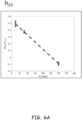
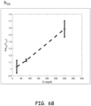
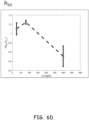
- FIGS. 6A-D illustrate semi-log plots of a ratio of the strength of various harmonics of a fundamental frequency of a periodic voltage signal applied to a glucose-containing fluid at three different concentrations in accordance with an example embodiment of the disclosure.
- various illustrative harmonic ratio curves are shown, respectively, for the ratio of the strength of a second harmonic to a strength of a third harmonic h 23 , the ratio of the strength of the third harmonic to a strength of a fifth harmonic h 35 , the ratio of the strength of a fourth harmonic to the strength of the fifth harmonic h 45 , and the ratio of the strength of the second harmonic to the strength of the fourth harmonic h 24 for different glucose concentrations in a sample (e.g., 50, 100 and 300 milligrams per deciliter (mg/dl)).
- glucose concentrations in a sample e.g., 50, 100 and 300 milligrams per deciliter (mg/dl)
- the strengths for the harmonics are determined by extracting the harmonics from the digitized time-domain current measurement signal (e.g., from third circuit 108 in FIGS. 1A, 1B or 1C , or from sampling circuit 214 in FIGS. 2 or 3 ), and identifying the strength (e.g., amplitude, power, etc.) of these spectral components of the digitized time-domain current measurement signals.
- a Fourier transform, a Discrete Fourier Transform, a Fast Fourier Transform, a Goertzel Transform, etc. may be used to extract spectral components.
- FIGS. 6A-D indicate that for any particular glucose concentration, there is a unique set of harmonic ratio values. Thus, a given set of harmonic ratio values maps to a unique corresponding glucose concentration.
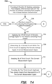
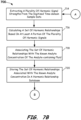
- FIGS. 7A-7B illustrate a flow diagram of a method 700 of generating a harmonic relationship database for a continuous analyte monitoring system in accordance with an example embodiment of the disclosure.
- example method 700 provides a method of producing a set of predetermined harmonic relationship information that is correlated to corresponding values of an analyte concentration in an analyte-containing fluid.
- a harmonic relationship database may be produced that may be used, for example, in CGM products in accordance with the present disclosure to determine glucose levels in human interstitial fluids.
- Method 700 may include providing 702 a plurality of analyte-containing fluid samples, wherein each one of the plurality of analyte-containing fluid samples has a known analyte concentration.
- the fluid samples contain known concentrations of glucose.
- a harmonic relationship database for a different analyte may be produced by using fluid samples containing known concentrations of that analyte. Because method 700 may be used to produce a set of harmonic relationship information for each of the plurality of analyte-containing fluid samples, a decision operation 704 is performed to determine whether all of the analyte-containing fluid samples have been processed. If all the fluid samples have been processed, then method 700 ends.
- method 700 further includes, for each one of the remaining plurality of analyte-containing fluid samples, applying 706, by a first circuit such as first circuit 102 of FIGS. 1A, 1B or 1C or signal generator 206 of FIGS. 2 or 3 , a periodic excitation (e.g., voltage) signal (having a fundamental frequency) to the analyte-containing fluid sample.
- a periodic excitation e.g., voltage
- Method 700 also includes generating 708, by a second circuit while the first circuit is applying the periodic voltage signal, a current measurement signal, where the current measurement signal has a magnitude indicative of a current produced by an oxidation-reduction reaction in the analyte-containing fluid sample while the first circuit is applying the periodic voltage signal, the magnitude of the current measurement signal being dependent, at least in part, on the analyte concentration in the analyte-containing fluid sample.
- the second circuit may be, for example, second circuit 106 of FIGS. 1A, 1B or 1C or current measuring circuit 212 of FIGS. 2 or 3 .
- Method 700 further includes sampling 710 the current measurement signal, by a third circuit, and providing 712 by the third circuit, digitized time-domain sample data representative of the current measurement signal.
- the third circuit may be, for example, third circuit 108 of FIGS. 1A, 1B or 1C or sampling circuit 214 of FIGS. 2 or 3 .
- the current measurement signal is a complex time-varying signal that may be represented by the summation of a series of signals each having its own frequency, amplitude, and phase characteristics, e.g., using Fourier transforms from the time-domain to the frequency-domain.
- the spectral content of a complex time-varying signal can be extracted, for example, by transforming a time-domain signal to a frequency-domain signal, and identifying the frequencies of the spectral peaks. Any suitable transform may be used such as a Fourier transform, a Discrete Fourier Transform, a Fast Fourier Transform, a Goertzel Transform, etc.
- Harmonic signals are signals having a frequency that is an integer multiple of a fundamental frequency, which in this example is the frequency of the periodic voltage signal applied to the analyte-containing fluid samples.
- method 700 continues by extracting 714, a plurality of harmonic signal strengths from the digitized time-domain sample data, and calculating 716 a set of harmonic relationships, such as harmonic ratios, based on at least a portion of the plurality of harmonic signals.
- Each extracted harmonic signal component has a value representative of the strength, e.g., amplitude, power, etc., of its corresponding harmonic frequency.
- the harmonic relationship determined may be a harmonic ratio that is the quotient of the strengths of at least two harmonic signals (e.g., the ratio of the strengths of at least two harmonic signals).
- a harmonic ratio may be the ratio of the strength of the third harmonic of the fundamental frequency and the fifth harmonic of the fundamental frequency.
- other functional relationships between harmonic signals and/or harmonic signal strengths may be used in addition to or in place of harmonic ratios.
- a plurality of harmonic relationships such as ratios of the strengths of a plurality of harmonics, may be used to identify concentrations of at least one analyte in an analyte-containing fluid.
- processors and/or microcontrollers 110, 120, 222, 230 and/or 308 of FIGS. 1A-3 may perform and/or otherwise assist in harmonic extraction and/or harmonic relationship calculations, using, for example, one or more time-domain to frequency-domain transforms (e.g., forming digitized frequency-domain data).
- Method 700 continues by associating 718 the set of harmonic relationships with the known analyte concentration of the analyte-containing fluid, and storing 720 the set of harmonic relationships associated with the known analyte concentration in a harmonic relationship database.
- a harmonic relationship database similar to harmonic relationship database 500 of FIG. 5 may be developed.
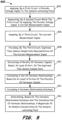
- FIG. 8 illustrates a flow diagram of a method 800 of determining an analyte concentration in accordance with an example embodiment of the disclosure.
- example method 800 provides for electronically probing an oxidation-reduction reaction in an analyte-containing fluid to determine a concentration of at least one analyte in the fluid.
- Method 800 includes applying 802, by a first circuit such as first circuit 102 of FIGS. 1A, 1B or 1C or signal generator 206 of FIGS.
- a periodic excitation (e.g., voltage) signal (having a fundamental frequency) to the analyte-containing fluid
- generating 804 by a second circuit while the first circuit is applying the periodic voltage signal, a current measurement signal, having a magnitude indicative of a current produced by an oxidation-reduction reaction in the analyte-containing fluid, the magnitude dependent, at least in part, on an analyte concentration in the analyte-containing fluid.
- the second circuit may be, for example, second circuit 106 of FIGS. 1A, 1B or 1C or current measuring circuit 212 of FIGS. 2 or 3 .
- Method 800 further includes sampling 806 the current measurement signal, by a third circuit, and providing 808, by the third circuit, digitized time-domain sample data representative of the current measurement signal.
- the sampling circuit may be an A/D converter having a suitable bit resolution.
- the third circuit may be, for example, third circuit 108 of FIGS. 1A, 1B or 1C or sampling circuit 214 of FIGS. 2 or 3 .
- method 800 continues by extracting 810 a plurality of harmonic signals based, at least in part, on the digitized time-domain sample data, wherein the harmonic signals are harmonics of the fundamental frequency, and each harmonic signal has a corresponding strength.
- Method 800 continues by calculating 812 a set of harmonic relationships of at least two harmonic strengths, such as harmonic ratios, based on at least a portion of the plurality of harmonic signals that have been extracted, and accessing 814 a harmonic relationship database, wherein the harmonic relationship database includes a plurality of sets of harmonic relationships (see, for example, FIG. 5 ), each set of harmonic relationships associated with a corresponding analyte concentration.
- Method 800 further includes determining 816, based on the harmonic relationship database and the calculated set of harmonic relationships, an analyte concentration in the analyte-containing fluid.
- determining the analyte concentration includes comparing the calculated set of harmonic relationships to one or more vectors in the harmonic relationship database (e.g., harmonic relationship database 500 of FIG. 5 ), and when a match is found between the calculated set of harmonic relationships and a vector in the harmonic relationship database, following the link, or pointer, associated with the matching vector to an associated analyte concentration value.
- processors and/or microcontrollers 110, 120, 222, 230 and/or 308 of FIGS. 1A-3 may perform and/or otherwise assist in harmonic extraction, harmonic relationship calculations, and/or determining the analyte concentration by comparing the calculated set of harmonic relationships to one or more vectors in a harmonic relationship database.
- harmonic ratios and/or other harmonic relationships may be correlated with analyte concentrations using numerical fits such as multivariate polynomials, multi-dimensional interpolation, such as using cubic splines, between experimentally measured datasets, or the like.
- harmonics and their derived attributes e.g., amplitude, power, etc.
- machine learning algorithms including but not limited to multivariate regression, neural networks, Newton-Raphson methods or conjugate gradient optimization for analyzing analyte concentrations or other properties.
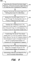
- FIG. 9 illustrates a flow diagram of a method 900 of continuous glucose monitoring in accordance with an example embodiment of the disclosure.
- method 900 provides generating 902, by a periodic excitation signal (e.g., an AC excitation signal, a periodic voltage signal, etc.) generator, a periodic signal having an amplitude and a fundamental frequency, and applying 904 the excitation signal to an electrode of the CGM sensor.
- a periodic excitation signal e.g., an AC excitation signal, a periodic voltage signal, etc.
- Method 900 continues by sensing 906, with a current sensor circuit, a current through the CGM sensor to produce a measured current signal.
- the measured current signal is dependent, at least in part, on the excitation signal, and at least in part on the glucose concentration in the person's interstitial fluid.
- Method 900 continues by sampling 908, with a sampling circuit, the measured current signal at a sampling rate, for a period of time, and at a bit resolution, to produce a set of time-domain sample data.
- the sampling rate is greater than the fundamental frequency of the excitation signal, for example, but not limited to, fifty times greater, one hundred times greater, or even two hundred times greater, or even four hundred times greater.
- Method 900 continues by transforming 910 the set of time-domain sample data to a set of frequency-domain data, wherein the set of frequency-domain data includes a strength of each one of a predetermined number of harmonics of the fundamental frequency.
- Method 900 further includes generating 912 a set of harmonic relationships based on a strength of each of the predetermined number of harmonics.
- Method 900 further includes determining 914 a glucose level (e.g., concentration) based on the set of harmonic relationships.
- the set of harmonic relationships may map to a concentration of glucose within a harmonic relationship database.
- Method 900 may be performed, for example, by one or more of CGM systems 100, 150, 170, 200 or 300.
- the frequency of the periodic excitation signal applied to an analyte-containing fluid may be selected based, at least in part, on an approximate concentration of analyte in the analyte-containing fluid.
- an approximate analyte concentration may be an expected analyte concentration (e.g., based on typical observed analyte concentrations for a patient, previous concentrations levels measured for the patient, time of day, when and/or what a patient last ate, etc.).
- a simple DC or other analyte concentration measurement may be performed to determine an approximate analyte concentration.
- the fundamental frequency of the periodic excitation signal may be determined. For example, for glucose, if the approximate analyte (e.g., glucose) concentration indicates an intermediate glucose concentration is present in a fluid to be analyzed, a frequency of about 0.5 to 1.5 Hz may be used for the periodic excitation signal. As another example, if the approximate analyte (e.g., glucose) concentration indicates a low glucose concentration is present in a fluid to be analyzed, a frequency of about 4.5 to 5.5 Hz may be used for the periodic excitation signal. Other frequencies may be used for these and/or other analyte concentrations. In some embodiments, basing selection of the frequency of the periodic excitation signal at least in part on an approximate analyte concentration may provide a more-accurate frequency domain based determination of analyte concentration.
- the approximate analyte concentration e.g., glucose
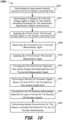
- FIG. 10 illustrates a flow diagram of a method 1000 of analyte-concentration monitoring in accordance with an example embodiment of the disclosure.
- method 1000 to determine an analyte concentration in an analyte-containing fluid, method 1000 provides determining 1002 an approximate analyte concentration for the analyte-containing fluid. As described above, this may include employing an expected analyte concentration, employing a simple DC analyte concentration measurement, or the like, to obtain an estimated or approximate analyte concentration level.
- Method 1000 then includes determining 1004 a frequency of a periodic excitation (e.g., voltage) signal to apply to the analyte-containing fluid based on the approximate analyte concentration.
- a periodic excitation e.g., voltage
- Method 1000 then includes applying 1006 the periodic signal to the analyte-containing fluid and generating 1008 a current measurement signal.
- the measured current signal is dependent, at least in part on the excitation signal, and at least in part on the analyte concentration in the analyte-containing fluid.
- Method 1000 continues by sampling 1010 the measured current signal to produce 1012 a set of time-domain sample data.
- the sampling rate is greater than the fundamental frequency of the excitation signal, for example, but not limited to, fifty times greater, one hundred times greater, or even two hundred times greater, or even four hundred times greater.
- Method 1000 continues by extracting 1014 a plurality of harmonic signals based, at least in part, on the digitized time-domain sample data and calculating 1016 a set of harmonic relationships based on at least a portion of the plurality of harmonic signals. For example, harmonic ratios and/or other combinations of two or more harmonic strengths may be employed to form a set of harmonic relationships. Method 1000 then includes determining 1018 analyte concentration for the analyte-containing fluid based on the set of harmonic relationships. In some embodiments, a harmonic relationship database, multivariate polynomials, multi-dimensional interpolation, such as using cubic splines, or the like may be used to determine analyte concentration. Method 1000 may be performed, for example, by one or more of the monitoring systems 100, 150, 170, 200 or 300, for example.
- the methods and systems described herein may be employed to determine concentration of analytes other than glucose, such as maltose, galactose, hematocrit, etc., interferents of such analytes, concentration of medications such as acetaminophen, or the like.
- Ratios or other relationships of at least two harmonic strengths as algorithm attributes may have less dependence on calibration compared to utilizing absolute current measurements.
- the advantage of an algorithm with a basis function set built upon the relationships of harmonics is that many harmonics (typically in the range of 10-20, or more) can be extracted, and the ratios or other functional relations among all these harmonics may represent hundreds of independent concurrent measurements.
- the harmonics may be extracted from any time range which is an integer multiple of the fundamental period of the excitation pulse.
- harmonics-based algorithm is scalable, allowing optimized deployment on different CPU platforms, ranging from efficient Goertzel transforms on small microcontrollers to full-scale, real-time Fourier analysis for higher-performance processors.
- the non-linear components in the current response are dependent on the glucose concentration in a repeatable manner.
- harmonic strength h n The Fourier transform S k from equation [2], extracted at the harmonic frequencies f n from equation [3] may be referred to as harmonic strength h n .
- different attributes may be formed, which are optimized to be correlated to the concentration of glucose, glucose interferents and/or the sensor temperature, where the correlation may be described through the most straightforward functional relationship.
- the advantage of this approach is to substantially normalize out the hardware calibration of the current sensing electronics. For example, if any DC offset is removed (e.g., if the extraction of the harmonics is set up as a well-conditioned digital filter), no absolute calibration of the current sensing electronics may be necessary.
- the harmonics ratios yield a number of N(N-1)/2 different attributes, which may be included in correlation functions with the glucose, temperature or glucose interferents, where N is the maximum number of measureable harmonics.
- N the maximum number of measureable harmonics.
- 105 different attributes may be used to build more complex functions, such as index functions, from the simple harmonics ratios alone.
- Embodiments disclosed herein may provide continuous measurements of the concentration of reagents in aqueous solutions by monitoring the ratios of harmonics in the current through the working electrode of a sensor. Continuous monitoring of numerous current harmonics permits self-calibration of signals in a CGM (e.g., without the need for DC current measurements and frequent calibrations).
- the attributes extracted using harmonics may eliminate the absolute current scale, decreasing the demands on (and cost of) sensor electronics and calibration. Attributes are independent of acquisition and can be readily analysed with any suitable algorithm.
- the above described embodiments may be implemented as a continuous algorithm, such as, for example, through a digital filter. Any operation on a continuous data stream can be described as a filter, such as a finite impulse response (FIR) filter, an infinite impulse response (IIR) filter or a recursive response (RR) filter.
- FIR finite impulse response
- IIR infinite impulse response
- RR recursive response
- the exact implementation may depend on the processing environment the algorithm will be deployed on, as well as the number of harmonics to be extracted.
- a batch algorithm such as the Fast Fourier Transform (FFT) may be used, which may be applied on a window ("timebins" in equations [4] and [5]), but with the periodicity of application far longer than the sampling time (e.g., determined by the expected rate of change of, in this case, the underlying chemistry).
- FFT Fast Fourier Transform
- an FFT may be applied every 1-5 minutes, on data windows covering less (possibly much less, such as a few seconds for severe CPU constraints) than 1-5 minutes.
- the Goertzel transform may be employed.
- Embodiments described herein may provide a more efficient method to perform measurements of glucose and possibly other analyte concentrations in a continuous acquisition and signal processing mode, yielding time-domain measurements which are delayed from ground truth in the interstitial fluid by a time interval which is small compared to the delay between arterial blood and interstitial fluid.
- the algorithm is compatible with any implementation of predictive modeling of hypo/hyperglycemic events (e.g., linear regression, auto-regressive predictive modeling, Kalman filtering or artificial neural networks).
- predictive modeling may be employed to generate one or more prediction equations that employ one or more sets of harmonic relationships, such as harmonic ratios, to determine analyte concentration during continuous analyte sensing (e.g., in place of or in addition to the use of a harmonic relationship database).
- harmonic relationships such as harmonic ratios
- multivariate regression may be employed with known analyte concentration as the regression target and a large number of harmonic relationships, such as harmonic ratios and/or other terms and/or cross terms, as the input parameters providing information gathered from the non-linear current response to a periodic excitation signal.
- one or more of such prediction equations may be stored in a memory of a continuous analyte sensing device and used to compute analyte values through use of harmonic relationships during continuous analyte sensing.
- one or more prediction equations may be stored in memory 112, 228 and/or 302 of CGM systems 100, 150, 170, 200 or 300.
- ratios of harmonics may eliminate the need for an "absolute" sensor calibration, relaxing the bit resolution of the analog-to-digital converter stage and reducing component cost and possibly complexity of the analog front end.
- the algorithm is very scalable, allowing optimized deployment on different CPU platforms, ranging from efficient Goertzel transforms on small microcontrollers to full-scale, real-time Fourier analysis for higher-performance processors.
- phase angle and/or power spectral density data may be generated from the digitized frequency-domain data and used for harmonic strength information.
- the non-wearable portion of an analyte monitoring system may include a mobile telephone, such as a smartphone, a smartwatch, or the like.
- various electronic components and circuits are configured to couple to a power supply, such as but not limited to, a battery.
- a battery may include a supercapacitor.
- one or more energy harvesting circuits such as the class of ubiquitous energy harvesting circuits well known for their use in RFID tags, may be used to charge a capacitor or a supercapacitor, which in turn acts as battery.
- the well-known class of energy harvesting circuits are configured to convert energy from an RF energization field into a regulated DC voltage.
- a charging current for a capacitor or supercapacitor may be supplied by a thermoelectric generator. The temperature gradient required to produce a voltage by the thermoelectric generator may be obtained from the difference between the skin of the user at that point of CGM attachment, and a distal end of the CGM disposed away from the point of attachment, for example.
- amperometry refers to the detection of ions in a solution, where that detection is based, at least in part, on sensing an electric current, or sensing changes in the electric current.
- a “processor” means any one or more microprocessors, one or more Central Processing Units (CPUs), one or more Graphics Processing Units (GPUs), one or more computing devices, one or more microcontrollers, one or more digital signal processors (DSPs), one or more embedded processors such as an embedded processor in a System on Chip (SoC), one or more field programmable gate arrays (FPGAs), like devices, or various combinations of the foregoing.
- CPUs Central Processing Units
- GPUs Graphics Processing Units
- DSPs digital signal processors
- SoC System on Chip
- FPGAs field programmable gate arrays
- Non-volatile media may include, for example, optical disks, magnetic disks, and other persistent memory.
- Volatile media may include, but are not limited to, static random access memory (SRAM), and dynamic random access memory (DRAM).
- Types of transmission media may include, for example, coaxial cables, electrically conductive wires, traces, or lines, including the wires, traces, or lines, that comprise a system bus coupled to the processor, and optical fibers.
- Computer-readable media may include, for example, a floppy disk, a flexible disk, a hard disk, a magnetic tape, any other magnetic medium, a CD-ROM, a Digital Video Disc (DVD), any other optical medium, punch cards, paper tape, any other physical medium with patterns of holes, a read-only memory (ROM), a random access memory (RAM), a programmable read-only memory (PROM), an electrically programmable read-only memory (EPROM), an electrically erasable programmable read-only memory (EEPROM), a flash memory (a type of EEPROM), a resistive memory, a filamentary memory, a metal oxide memory, a phase change memory, a spin transfer memory, a USB memory stick, any other memory chip or cartridge, or any other medium from which a computer, or processor, can access the data or instructions stored therein.
- the terms "computer-readable memory” and/or “tangible media” specifically exclude signals, waves, and wave forms or other intangible or transitory
- nominal refers to a desired, or target, value of a characteristic, measurement, or other parameter for a component, product, signal, or process, together with a range of values above or below the desired value.
- the range of values is typically due to slight variations in manufacturing processes, or tolerances.
- a or B is meant to include A alone, B alone, and A and B together. In the case where A alone, B alone, and not A and B together, is meant to be expressed, this will be explicitly stated. At least one of A and B is meant to include A alone, B alone and A and B.
- An enumerated list of items does not imply that any or all of the items are mutually exclusive, unless expressly specified otherwise.
- an enumerated list of items does not imply that any or all of the items are comprehensive of any category, unless expressly specified otherwise.
- the enumerated list "a computer, a laptop, a smartphone,” does not imply that any or all of the three items of that list are mutually exclusive and does not imply that any or all of the three items of that list are comprehensive of any category.
- first, second, etc. may be used herein to describe various elements, components, regions, parts or sections, these elements, components, regions, parts or sections, should not be limited by these terms. The terms may be used to distinguish one element, component, region, part or section, from another element, component, region, part or section. For example, a first element, component, region, part or section discussed above could be termed a second element, component, region, part or section without departing from the teachings of the present disclosure.
- First, second or third circuits may be subcomponents of one or more other circuits.
Landscapes
- Health & Medical Sciences (AREA)
- Life Sciences & Earth Sciences (AREA)
- Engineering & Computer Science (AREA)
- Physics & Mathematics (AREA)
- Molecular Biology (AREA)
- General Health & Medical Sciences (AREA)
- Pathology (AREA)
- Biomedical Technology (AREA)
- Surgery (AREA)
- Medical Informatics (AREA)
- Biophysics (AREA)
- Animal Behavior & Ethology (AREA)
- Public Health (AREA)
- Veterinary Medicine (AREA)
- Heart & Thoracic Surgery (AREA)
- General Physics & Mathematics (AREA)
- Chemical & Material Sciences (AREA)
- Mathematical Physics (AREA)
- Signal Processing (AREA)
- Hematology (AREA)
- Optics & Photonics (AREA)
- Immunology (AREA)
- Psychiatry (AREA)
- Physiology (AREA)
- Computer Vision & Pattern Recognition (AREA)
- Artificial Intelligence (AREA)
- Theoretical Computer Science (AREA)
- Analytical Chemistry (AREA)
- Chemical Kinetics & Catalysis (AREA)
- Biochemistry (AREA)
- Computer Networks & Wireless Communication (AREA)
- General Engineering & Computer Science (AREA)
- General Chemical & Material Sciences (AREA)
- Computer Hardware Design (AREA)
- Mathematical Analysis (AREA)
- Data Mining & Analysis (AREA)
- Urology & Nephrology (AREA)
- Pure & Applied Mathematics (AREA)
- Mathematical Optimization (AREA)
- Computational Mathematics (AREA)
Claims (14)
- Ein Verfahren (800) zum elektronischen Untersuchen einer Oxidations-Reduktions-Reaktion in einem einen Analyten enthaltenden Fluid, umfassend:Anlegen (802), durch eine erste Schaltung, eines periodischen Spannungsanregungssignals an eine erste Elektrode eines CGM-Sensors, der in dem einen Analyten enthaltenden Fluid angeordnet ist, wobei das periodische Spannungsanregungssignal eine Grundfrequenz aufweist;Erzeugen (804), durch eine zweite Schaltung, eines Strommesssignals mit einer Größe eines von dem CGM-Sensor gelieferten Stroms während die erste Schaltung das periodische Spannungsanregungssignal anlegt, wobei der Strom durch eine Oxidations-Reduktions-Reaktion in der einen Analyten enthaltenden Fluid erzeugt wird und wobei die Größe des Strommesssignals zumindest teilweise von einer Glukosekonzentration in der einen Analyten enthaltenden Fluid abhängig ist;Abtasten (806), durch eine dritte Schaltung, die mit der zweiten Schaltung verbunden ist, des Strommesssignals;Bereitstellen (808), durch die dritte Schaltung, von digitalisierten Zeitbereichs-Abtastdaten, die für das Strommesssignal repräsentativ sind;Extrahieren (810) einer Mehrzahl von Oberschwingungssignalen zumindest teilweise auf der Grundlage der digitalisierten Zeitbereichs-Abtastdaten, wobei die Oberschwingungssignale Oberschwingungen der Grundfrequenz sind und jedes Oberschwingungssignal eine entsprechende Stärke aufweist, wobei das Extrahieren ein Transformieren der digitalisierten Zeitbereichs-Abtastdaten in digitalisierte Frequenzbereichsdaten umfasst;Berechnen (812) eines Satzes von harmonischen Verhältnissen auf der Grundlage von mindestens einem Teil der Mehrzahl von harmonischen Signalen;Zugreifen (814) auf eine harmonische Beziehungsdatenbank, wobei die harmonische Beziehungsdatenbank eine Mehrzahl von Vektoren umfasst, wobei jeder Vektor einen Satz von harmonischen Verhältnissen umfasst und wobei jeder Vektor mit einer entsprechenden Glukosekonzentration assoziiert ist; undBestimmen (816) der Glukosekonzentration in dem einen Analyten enthaltenden Fluid als der Glukosekonzentrationswert, der mit einem Vektor in der harmonischen Beziehungsdatenbank assoziiert ist, der mit dem berechneten Satz von harmonischen Verhältnissen übereinstimmt.
- Das Verfahren nach Anspruch 1, ferner umfassend:
Erzeugen von Leistungsspektraldichte-Daten aus den digitalisierten Frequenzbereichsdaten. - Das Verfahren nach Anspruch 1, wobei das Zugreifen auf die die harmonische Beziehungsdatenbank umfasst:
Zugreifen auf eine Nachschlagetabelle. - Das Verfahren nach Anspruch 1, ferner umfassend ein drahtloses Übertragen der digitalisierten Zeitbereichsabtastdaten, die für das Strommesssignal repräsentativ sind, von einem tragbaren Gerät zur kontinuierlichen Glukoseüberwachung an ein Smartphone.
- Das Verfahren nach Anspruch 1, wobei das Abtasten des Strommesssignals ein Abtasten mit einer ersten Abtastrate in einem Bereich von 10 Abtastungen pro Sekunde bis 1000 Abtastungen pro Sekunde für eine erste Zeitspanne umfasst.
- Das Verfahren nach Anspruch 5, wobei die erste Zeitspanne in einem Bereich von 10 Sekunden bis 300 Sekunden liegt.
- Das Verfahren nach Anspruch 1, wobei die Grundfrequenz des periodischen Spannungsanregungssignals in einem Bereich von 0,1 Hz bis 10 Hz liegt und/oder das periodische Anregungssignal eine Amplitude in einem Bereich von 150 Millivolt bis 500 Millivolt aufweist.
- Verfahren nach Anspruch 1, wobei das Bestimmen der Größe der Glukosekonzentration in dem einen Analyten enthaltenden Fluid durch einen tragbaren Teil eines Analytüberwachungssystems durchgeführt wird.
- Das Verfahren nach Anspruch 8, ferner umfassend Anzeigen der Glukosekonzentration auf einem Display des tragbaren Teils.
- Das Verfahren nach Anspruch 1, ferner umfassend Verwenden der berechneten harmonischen Verhältnisse zum Unterscheiden der Glukose von mindestens einem Störfaktor.
- Ein kontinuierliches Analyt Überwachung (CAM) System (100, 150, 170), umfassend:
einen CGM-Sensor (104):eine erste Schaltung (102) eingerichtet zum Anlegen eines periodischen Spannungsanregungssignals an eine erste Elektrode des CGM-Sensors, der sich in einem einen Analyten enthaltenden Fluid;eine zweite Schaltung (106) eingerichtet zum Erzeugen eines Strommesssignals, das eine Größe eines von dem CGM-Sensor übertragenen Stroms aufweist, wobei der Strom durch eine Oxidations-Reduktions-Reaktion in dem einen Analyten enthaltenden Fluid erzeugt wird, und wobei die Größe des Strommesssignals zumindest teilweise von einer Glukosekonzentration in dem einen Analyten enthaltenden Fluid abhängt;eine dritte Schaltung (108), die mit der zweiten Schaltung gekoppelt und eingerichtet ist zum Abtasten des Strommesssignals, und die ferner eingerichtet ist zum Erzeugen von digitalisierten Zeitbereichs-Abtastdaten; undeinen Prozessor (110, 120), der mit einem Speicher (112) gekoppelt ist, wobei in dem Speicher eine harmonische Beziehungsdatenbank (114, 400, 500) gespeichert ist, und wobei ferner darin Anweisungen gespeichert sind, die, wenn sie von dem Prozessor ausgeführt werden, den Prozessor veranlassen, Folgendes zu tunExtrahieren einer Mehrzahl von Oberschwingungssignalen aus den digitalisierten Zeitbereichs-Abtastdaten, was das Transformieren der digitalisierten Zeitbereichs-Abtastdaten in Frequenzbereichsdaten umfasst;Berechnen eines Satzes von Oberschwingungsverhältnissen auf der Grundlage von mindestens einem Teil der mehreren Oberschwingungssignale;Zugreifen auf die harmonische Beziehungsdatenbank, wobei die harmonische Beziehungsdatenbank eine Mehrzahl von Vektoren umfasst, wobei jeder Vektor einen Satz von harmonischen Verhältnissen umfasst und wobei jeder Vektor mit einer entsprechenden Glukosekonzentration assoziiert ist; undBestimmen der Glukosekonzentration in dem einen Analyten enthaltenen Fluid als den Glukosekonzentrationswert, der mit einem Vektor in der harmonische Beziehungsdatenbank assoziiert ist, der mit dem berechneten Satz harmonischer Verhältnisse übereinstimmt. - CAM-System nach Anspruch 11, wobei der erste Schaltkreis, der zweite Schaltkreis und der dritte Schaltkreis in einer tragbaren Vorrichtung (116) angeordnet sind.
- CAM-System nach Anspruch 12, wobei der Prozessor und der Speicher in der tragbaren Vorrichtung angeordnet sind.
- CAM-System nach Anspruch 11, wobei die Anweisungen, wenn sie von dem Prozessor ausgeführt werden, den Prozessor zudem veranlassen, einen drahtlosen Sender (218, 304) anzuweisen, die Glukosekonzentration zu übertragen.
Applications Claiming Priority (2)
| Application Number | Priority Date | Filing Date | Title |
|---|---|---|---|
| US201962809039P | 2019-02-22 | 2019-02-22 | |
| PCT/EP2020/054459 WO2020169719A1 (en) | 2019-02-22 | 2020-02-20 | Methods and apparatus for analyte concentration monitoring using harmonic relationships |
Publications (2)
| Publication Number | Publication Date |
|---|---|
| EP3928089A1 EP3928089A1 (de) | 2021-12-29 |
| EP3928089B1 true EP3928089B1 (de) | 2025-05-14 |
Family
ID=69714012
Family Applications (1)
| Application Number | Title | Priority Date | Filing Date |
|---|---|---|---|
| EP20707381.8A Active EP3928089B1 (de) | 2019-02-22 | 2020-02-20 | Verfahren und system zur überwachung einer glukosekonzentration unter verwendung von harmonischen beziehungen |
Country Status (5)
| Country | Link |
|---|---|
| US (2) | US11445944B2 (de) |
| EP (1) | EP3928089B1 (de) |
| JP (1) | JP7813139B2 (de) |
| CN (1) | CN113646625A (de) |
| WO (1) | WO2020169719A1 (de) |
Families Citing this family (4)
| Publication number | Priority date | Publication date | Assignee | Title |
|---|---|---|---|---|
| JP7494194B2 (ja) | 2019-02-05 | 2024-06-03 | アセンシア・ディアベティス・ケア・ホールディングス・アーゲー | 連続的分析物感知および自動較正のセンサ動作を精査するための装置および方法 |
| EP3928089B1 (de) | 2019-02-22 | 2025-05-14 | Ascensia Diabetes Care Holdings AG | Verfahren und system zur überwachung einer glukosekonzentration unter verwendung von harmonischen beziehungen |
| US11963763B2 (en) | 2019-09-10 | 2024-04-23 | Ascensia Diabetes Care Holdings Ag | Methods and apparatus information gathering, error detection and analyte concentration determination during continuous analyte sensing |
| CN117129442A (zh) * | 2023-08-09 | 2023-11-28 | 北京辰安科技股份有限公司 | 激光气体传感器的谐波信号处理方法及系统 |
Family Cites Families (34)
| Publication number | Priority date | Publication date | Assignee | Title |
|---|---|---|---|---|
| US5792668A (en) * | 1993-08-06 | 1998-08-11 | Solid State Farms, Inc. | Radio frequency spectral analysis for in-vitro or in-vivo environments |
| US5958215A (en) * | 1995-09-18 | 1999-09-28 | The Regents Of The University Of Califronia | Detection of purine and pyrimidine nucleotides and underivatized nucleic acids by sinusoidal voltammetry |
| WO2001021827A1 (en) | 1999-09-20 | 2001-03-29 | Roche Diagnostics Corporation | Small volume biosensor for continuous analyte monitoring |
| WO2001088534A2 (en) | 2000-05-16 | 2001-11-22 | Cygnus, Inc. | Methods for improving performance and reliability of biosensors |
| US20030104386A1 (en) * | 2001-08-31 | 2003-06-05 | The Regents Of The University Of California | Methods for the specific detection of redox-active tags and the use thereof for capillary gel electrophoresis and DNA sequencing |
| CN1615434A (zh) * | 2002-01-15 | 2005-05-11 | 埃葛梅崔克斯股份有限公司 | 适用于处理电化学信号的方法和装置 |
| CA2480550C (en) | 2002-03-22 | 2011-07-12 | Cygnus, Inc. | Improving performance of an analyte monitoring device |
| US20070264721A1 (en) * | 2003-10-17 | 2007-11-15 | Buck Harvey B | System and method for analyte measurement using a nonlinear sample response |
| US7299082B2 (en) | 2003-10-31 | 2007-11-20 | Abbott Diabetes Care, Inc. | Method of calibrating an analyte-measurement device, and associated methods, devices and systems |
| EP2316331B1 (de) | 2003-12-09 | 2016-06-29 | Dexcom, Inc. | Signalverarbeitung in einem durchgehenden Analytsensor |
| US8057401B2 (en) | 2005-02-24 | 2011-11-15 | Erich Wolf | System for transcutaneous monitoring of intracranial pressure |
| US20060094944A1 (en) | 2004-10-28 | 2006-05-04 | Sontra Medical Corporation | System and method for analyte sampling and analysis with error correction |
| EP3483599A1 (de) | 2005-07-20 | 2019-05-15 | Ascensia Diabetes Care Holdings AG | Verfahren zur messung der konzentration eines analyten in lösung und zum kalibrieren der messung sowie tragbare geräte dafür |
| US20080077015A1 (en) * | 2006-05-17 | 2008-03-27 | Olga Boric-Lubecke | Determining presence and/or physiological motion of one or more subjects with multiple receiver Doppler radar systems |
| US8126554B2 (en) | 2006-05-17 | 2012-02-28 | Cardiac Pacemakers, Inc. | Implantable medical device with chemical sensor and related methods |
| US20070299617A1 (en) | 2006-06-27 | 2007-12-27 | Willis John P | Biofouling self-compensating biosensor |
| RU2509304C2 (ru) | 2008-12-08 | 2014-03-10 | БАЙЕР ХЕЛТКЭА ЭлЭлСи | Биосенсорная система с корректировкой сигнала |
| WO2010121229A1 (en) | 2009-04-16 | 2010-10-21 | Abbott Diabetes Care Inc. | Analyte sensor calibration management |
| US20110168575A1 (en) * | 2010-01-08 | 2011-07-14 | Roche Diaagnostics Operations, Inc. | Sample characterization based on ac measurement methods |
| KR102068949B1 (ko) | 2010-06-07 | 2020-01-21 | 바이엘 헬쓰케어 엘엘씨 | 2차 출력 신호를 포함하는 기울기-기반 보상 |
| US9008744B2 (en) | 2011-05-06 | 2015-04-14 | Medtronic Minimed, Inc. | Method and apparatus for continuous analyte monitoring |
| EP3586831A1 (de) | 2011-09-21 | 2020-01-01 | Ascensia Diabetes Care Holdings AG | Analyseausgleich mit segmentierten signalen |
| WO2014046318A1 (ko) | 2012-09-21 | 2014-03-27 | ㈜ 더바이오 | 시료를 인식하는 방법 및 이를 이용한 바이오센서 |
| EP3662833B1 (de) | 2013-02-20 | 2025-06-04 | Dexcom, Inc. | Retrospektive nachrüstverfahren zur erzeugung eines kontinuierlichen glucosekonzentrationsprofils |
| US9486171B2 (en) | 2013-03-15 | 2016-11-08 | Tandem Diabetes Care, Inc. | Predictive calibration |
| US20150073718A1 (en) * | 2013-09-10 | 2015-03-12 | Lifescan Scotland Limited | Phase-difference determination using test meter |
| CN106456072A (zh) * | 2014-03-12 | 2017-02-22 | 血糖测试仪股份有限公司 | 可穿戴的电化学传感器和方法 |
| EP3151732A1 (de) * | 2014-06-06 | 2017-04-12 | Dexcom, Inc. | Fehlerdiskriminierung und darauf reagierende verarbeitung auf grundlage von daten und kontext |
| WO2016054079A1 (en) * | 2014-09-29 | 2016-04-07 | Zyomed Corp. | Systems and methods for blood glucose and other analyte detection and measurement using collision computing |
| PT3430386T (pt) | 2016-03-18 | 2024-02-01 | Univ La Trobe | Análise voltamperométrica móvel |
| CA3061574C (en) | 2017-07-03 | 2022-07-26 | F. Hoffmann-La Roche Ag | Method and electronics unit for detecting in-vivo properties of a biosensor |
| CN109199403A (zh) * | 2017-07-04 | 2019-01-15 | 爱科来株式会社 | 测定装置、计算机可读取的记录介质以及测定方法 |
| EP4400047B1 (de) | 2017-11-01 | 2025-09-24 | Konamite Limited | Verfahren zur konditionierung eines sensors |
| EP3928089B1 (de) | 2019-02-22 | 2025-05-14 | Ascensia Diabetes Care Holdings AG | Verfahren und system zur überwachung einer glukosekonzentration unter verwendung von harmonischen beziehungen |
-
2020
- 2020-02-20 EP EP20707381.8A patent/EP3928089B1/de active Active
- 2020-02-20 JP JP2021549382A patent/JP7813139B2/ja active Active
- 2020-02-20 CN CN202080025607.9A patent/CN113646625A/zh active Pending
- 2020-02-20 US US16/796,906 patent/US11445944B2/en active Active
- 2020-02-20 WO PCT/EP2020/054459 patent/WO2020169719A1/en not_active Ceased
- 2020-02-20 US US16/796,920 patent/US11666253B2/en active Active
Also Published As
| Publication number | Publication date |
|---|---|
| JP2022521409A (ja) | 2022-04-07 |
| CN113646625A (zh) | 2021-11-12 |
| US20200268290A1 (en) | 2020-08-27 |
| JP7813139B2 (ja) | 2026-02-12 |
| WO2020169719A1 (en) | 2020-08-27 |
| US20200268323A1 (en) | 2020-08-27 |
| US11666253B2 (en) | 2023-06-06 |
| EP3928089A1 (de) | 2021-12-29 |
| US11445944B2 (en) | 2022-09-20 |
Similar Documents
| Publication | Publication Date | Title |
|---|---|---|
| US11445944B2 (en) | Methods and apparatus for analyte concentration monitoring using harmonic relationships | |
| CN104958075B (zh) | 使用拉曼光谱非侵入性测量皮肤厚度和血糖浓度及其校准方法 | |
| EP3478155B1 (de) | Verfahren zur bestimmung eines signalqualitätsgrads eines in einem kontinuierlichen überwachungssystem gemessenen analytwerts | |
| Facchinetti et al. | Reconstruction of glucose in plasma from interstitial fluid continuous glucose monitoring data: role of sensor calibration | |
| JP7840928B2 (ja) | 接続関数による連続分析物モニタリングセンサの較正及び測定 | |
| EP3920798B1 (de) | Vorrichtung und verfahren zum abtastsensorbetrieb mit kontinuierlicher analytmessung und autokalibrierung | |
| US20140046156A1 (en) | Method and System for Providing Calibration of an Analyte Sensor in an Analyte Monitoring System | |
| CN107847191A (zh) | 绷带型分析传感器的校准方法 | |
| KR20040077722A (ko) | 전기 화학 신호를 프로세싱하기 위한 방법 및 장치 | |
| EP3649942A1 (de) | Optischer sensor, verfahren zur messung eines optischen signals und vorrichtung zur schätzung der blutkonzentration eines analyts | |
| Jain et al. | An IoMT based non-invasive precise blood glucose measurement system | |
| Yun et al. | A novel approach for extracting contact impedance of electrode/electrolyte interface by minimizing error between impulse response and system function | |
| Shaham et al. | On mappings between electronic noses | |
| JP7635996B2 (ja) | 搬送流体中の現在のグルコース濃度を測定する方法 | |
| Olarte et al. | Using the best linear approximation as a first step to a new non-invasive glucose measurement | |
| EP4316370A1 (de) | Verfahren und system zur analytkonzentrationsdetektion auf der basis eines oszillators mit selektiver frequenzcharakteristik | |
| EP3230726A1 (de) | Analytenmessung |
Legal Events
| Date | Code | Title | Description |
|---|---|---|---|
| STAA | Information on the status of an ep patent application or granted ep patent |
Free format text: STATUS: UNKNOWN |
|
| STAA | Information on the status of an ep patent application or granted ep patent |
Free format text: STATUS: THE INTERNATIONAL PUBLICATION HAS BEEN MADE |
|
| PUAI | Public reference made under article 153(3) epc to a published international application that has entered the european phase |
Free format text: ORIGINAL CODE: 0009012 |
|
| STAA | Information on the status of an ep patent application or granted ep patent |
Free format text: STATUS: REQUEST FOR EXAMINATION WAS MADE |
|
| 17P | Request for examination filed |
Effective date: 20210818 |
|
| AK | Designated contracting states |
Kind code of ref document: A1 Designated state(s): AL AT BE BG CH CY CZ DE DK EE ES FI FR GB GR HR HU IE IS IT LI LT LU LV MC MK MT NL NO PL PT RO RS SE SI SK SM TR |
|
| DAV | Request for validation of the european patent (deleted) | ||
| DAX | Request for extension of the european patent (deleted) | ||
| STAA | Information on the status of an ep patent application or granted ep patent |
Free format text: STATUS: EXAMINATION IS IN PROGRESS |
|
| 17Q | First examination report despatched |
Effective date: 20230419 |
|
| P01 | Opt-out of the competence of the unified patent court (upc) registered |
Effective date: 20230512 |
|
| GRAP | Despatch of communication of intention to grant a patent |
Free format text: ORIGINAL CODE: EPIDOSNIGR1 |
|
| STAA | Information on the status of an ep patent application or granted ep patent |
Free format text: STATUS: GRANT OF PATENT IS INTENDED |
|
| INTG | Intention to grant announced |
Effective date: 20241217 |
|
| RIC1 | Information provided on ipc code assigned before grant |
Ipc: H04Q 9/00 20060101ALI20241209BHEP Ipc: A61B 5/145 20060101ALI20241209BHEP Ipc: A61B 5/0538 20210101ALI20241209BHEP Ipc: A61B 5/0537 20210101ALI20241209BHEP Ipc: A61B 5/053 20210101ALI20241209BHEP Ipc: G01N 27/327 20060101AFI20241209BHEP |
|
| GRAS | Grant fee paid |
Free format text: ORIGINAL CODE: EPIDOSNIGR3 |
|
| GRAA | (expected) grant |
Free format text: ORIGINAL CODE: 0009210 |
|
| STAA | Information on the status of an ep patent application or granted ep patent |
Free format text: STATUS: THE PATENT HAS BEEN GRANTED |
|
| AK | Designated contracting states |
Kind code of ref document: B1 Designated state(s): AL AT BE BG CH CY CZ DE DK EE ES FI FR GB GR HR HU IE IS IT LI LT LU LV MC MK MT NL NO PL PT RO RS SE SI SK SM TR |
|
| REG | Reference to a national code |
Ref country code: GB Ref legal event code: FG4D |
|
| REG | Reference to a national code |
Ref country code: CH Ref legal event code: EP |
|
| REG | Reference to a national code |
Ref country code: DE Ref legal event code: R096 Ref document number: 602020051220 Country of ref document: DE |
|
| REG | Reference to a national code |
Ref country code: IE Ref legal event code: FG4D |
|
| REG | Reference to a national code |
Ref country code: NL Ref legal event code: MP Effective date: 20250514 |
|
| PG25 | Lapsed in a contracting state [announced via postgrant information from national office to epo] |
Ref country code: PT Free format text: LAPSE BECAUSE OF FAILURE TO SUBMIT A TRANSLATION OF THE DESCRIPTION OR TO PAY THE FEE WITHIN THE PRESCRIBED TIME-LIMIT Effective date: 20250915 Ref country code: ES Free format text: LAPSE BECAUSE OF FAILURE TO SUBMIT A TRANSLATION OF THE DESCRIPTION OR TO PAY THE FEE WITHIN THE PRESCRIBED TIME-LIMIT Effective date: 20250514 Ref country code: FI Free format text: LAPSE BECAUSE OF FAILURE TO SUBMIT A TRANSLATION OF THE DESCRIPTION OR TO PAY THE FEE WITHIN THE PRESCRIBED TIME-LIMIT Effective date: 20250514 |
|
| REG | Reference to a national code |
Ref country code: LT Ref legal event code: MG9D |
|
| PG25 | Lapsed in a contracting state [announced via postgrant information from national office to epo] |
Ref country code: GR Free format text: LAPSE BECAUSE OF FAILURE TO SUBMIT A TRANSLATION OF THE DESCRIPTION OR TO PAY THE FEE WITHIN THE PRESCRIBED TIME-LIMIT Effective date: 20250815 Ref country code: NO Free format text: LAPSE BECAUSE OF FAILURE TO SUBMIT A TRANSLATION OF THE DESCRIPTION OR TO PAY THE FEE WITHIN THE PRESCRIBED TIME-LIMIT Effective date: 20250814 |
|
| PG25 | Lapsed in a contracting state [announced via postgrant information from national office to epo] |
Ref country code: PL Free format text: LAPSE BECAUSE OF FAILURE TO SUBMIT A TRANSLATION OF THE DESCRIPTION OR TO PAY THE FEE WITHIN THE PRESCRIBED TIME-LIMIT Effective date: 20250514 Ref country code: NL Free format text: LAPSE BECAUSE OF FAILURE TO SUBMIT A TRANSLATION OF THE DESCRIPTION OR TO PAY THE FEE WITHIN THE PRESCRIBED TIME-LIMIT Effective date: 20250514 |
|
| REG | Reference to a national code |
Ref country code: AT Ref legal event code: MK05 Ref document number: 1795161 Country of ref document: AT Kind code of ref document: T Effective date: 20250514 |
|
| PG25 | Lapsed in a contracting state [announced via postgrant information from national office to epo] |
Ref country code: BG Free format text: LAPSE BECAUSE OF FAILURE TO SUBMIT A TRANSLATION OF THE DESCRIPTION OR TO PAY THE FEE WITHIN THE PRESCRIBED TIME-LIMIT Effective date: 20250514 |
|
| PG25 | Lapsed in a contracting state [announced via postgrant information from national office to epo] |
Ref country code: HR Free format text: LAPSE BECAUSE OF FAILURE TO SUBMIT A TRANSLATION OF THE DESCRIPTION OR TO PAY THE FEE WITHIN THE PRESCRIBED TIME-LIMIT Effective date: 20250514 |
|
| PG25 | Lapsed in a contracting state [announced via postgrant information from national office to epo] |
Ref country code: AT Free format text: LAPSE BECAUSE OF FAILURE TO SUBMIT A TRANSLATION OF THE DESCRIPTION OR TO PAY THE FEE WITHIN THE PRESCRIBED TIME-LIMIT Effective date: 20250514 |
|
| PG25 | Lapsed in a contracting state [announced via postgrant information from national office to epo] |
Ref country code: RS Free format text: LAPSE BECAUSE OF FAILURE TO SUBMIT A TRANSLATION OF THE DESCRIPTION OR TO PAY THE FEE WITHIN THE PRESCRIBED TIME-LIMIT Effective date: 20250814 |
|
| PG25 | Lapsed in a contracting state [announced via postgrant information from national office to epo] |
Ref country code: IS Free format text: LAPSE BECAUSE OF FAILURE TO SUBMIT A TRANSLATION OF THE DESCRIPTION OR TO PAY THE FEE WITHIN THE PRESCRIBED TIME-LIMIT Effective date: 20250914 |
|
| PG25 | Lapsed in a contracting state [announced via postgrant information from national office to epo] |
Ref country code: LV Free format text: LAPSE BECAUSE OF FAILURE TO SUBMIT A TRANSLATION OF THE DESCRIPTION OR TO PAY THE FEE WITHIN THE PRESCRIBED TIME-LIMIT Effective date: 20250514 |
|
| PG25 | Lapsed in a contracting state [announced via postgrant information from national office to epo] |
Ref country code: DK Free format text: LAPSE BECAUSE OF FAILURE TO SUBMIT A TRANSLATION OF THE DESCRIPTION OR TO PAY THE FEE WITHIN THE PRESCRIBED TIME-LIMIT Effective date: 20250514 Ref country code: SM Free format text: LAPSE BECAUSE OF FAILURE TO SUBMIT A TRANSLATION OF THE DESCRIPTION OR TO PAY THE FEE WITHIN THE PRESCRIBED TIME-LIMIT Effective date: 20250514 |
|
| PG25 | Lapsed in a contracting state [announced via postgrant information from national office to epo] |
Ref country code: CZ Free format text: LAPSE BECAUSE OF FAILURE TO SUBMIT A TRANSLATION OF THE DESCRIPTION OR TO PAY THE FEE WITHIN THE PRESCRIBED TIME-LIMIT Effective date: 20250514 |
|
| PG25 | Lapsed in a contracting state [announced via postgrant information from national office to epo] |
Ref country code: EE Free format text: LAPSE BECAUSE OF FAILURE TO SUBMIT A TRANSLATION OF THE DESCRIPTION OR TO PAY THE FEE WITHIN THE PRESCRIBED TIME-LIMIT Effective date: 20250514 |
|
| PG25 | Lapsed in a contracting state [announced via postgrant information from national office to epo] |
Ref country code: RO Free format text: LAPSE BECAUSE OF FAILURE TO SUBMIT A TRANSLATION OF THE DESCRIPTION OR TO PAY THE FEE WITHIN THE PRESCRIBED TIME-LIMIT Effective date: 20250514 Ref country code: SK Free format text: LAPSE BECAUSE OF FAILURE TO SUBMIT A TRANSLATION OF THE DESCRIPTION OR TO PAY THE FEE WITHIN THE PRESCRIBED TIME-LIMIT Effective date: 20250514 |
|
| REG | Reference to a national code |
Ref country code: DE Ref legal event code: R097 Ref document number: 602020051220 Country of ref document: DE |
|
| PLBE | No opposition filed within time limit |
Free format text: ORIGINAL CODE: 0009261 |
|
| STAA | Information on the status of an ep patent application or granted ep patent |
Free format text: STATUS: NO OPPOSITION FILED WITHIN TIME LIMIT |
|
| REG | Reference to a national code |
Ref country code: CH Ref legal event code: L10 Free format text: ST27 STATUS EVENT CODE: U-0-0-L10-L00 (AS PROVIDED BY THE NATIONAL OFFICE) Effective date: 20260325 |
|
| 26N | No opposition filed |
Effective date: 20260217 |
|
| PG25 | Lapsed in a contracting state [announced via postgrant information from national office to epo] |
Ref country code: LT Free format text: LAPSE BECAUSE OF FAILURE TO SUBMIT A TRANSLATION OF THE DESCRIPTION OR TO PAY THE FEE WITHIN THE PRESCRIBED TIME-LIMIT Effective date: 20250514 |
|
| PG25 | Lapsed in a contracting state [announced via postgrant information from national office to epo] |
Ref country code: SE Free format text: LAPSE BECAUSE OF FAILURE TO SUBMIT A TRANSLATION OF THE DESCRIPTION OR TO PAY THE FEE WITHIN THE PRESCRIBED TIME-LIMIT Effective date: 20250514 |