EP3927445B1 - Ladedrehscheibensysteme und -verfahren - Google Patents
Ladedrehscheibensysteme und -verfahren Download PDFInfo
- Publication number
- EP3927445B1 EP3927445B1 EP20714343.9A EP20714343A EP3927445B1 EP 3927445 B1 EP3927445 B1 EP 3927445B1 EP 20714343 A EP20714343 A EP 20714343A EP 3927445 B1 EP3927445 B1 EP 3927445B1
- Authority
- EP
- European Patent Office
- Prior art keywords
- ride
- ride vehicle
- loading
- path
- attraction
- Prior art date
- Legal status (The legal status is an assumption and is not a legal conclusion. Google has not performed a legal analysis and makes no representation as to the accuracy of the status listed.)
- Active
Links
Images


Classifications
-
- A—HUMAN NECESSITIES
- A63—SPORTS; GAMES; AMUSEMENTS
- A63G—MERRY-GO-ROUNDS; SWINGS; ROCKING-HORSES; CHUTES; SWITCHBACKS; SIMILAR DEVICES FOR PUBLIC AMUSEMENT
- A63G1/00—Roundabouts
-
- A—HUMAN NECESSITIES
- A63—SPORTS; GAMES; AMUSEMENTS
- A63G—MERRY-GO-ROUNDS; SWINGS; ROCKING-HORSES; CHUTES; SWITCHBACKS; SIMILAR DEVICES FOR PUBLIC AMUSEMENT
- A63G21/00—Chutes; Helter-skelters
- A63G21/06—Chutes; Helter-skelters with passing arrangements for cars
-
- A—HUMAN NECESSITIES
- A63—SPORTS; GAMES; AMUSEMENTS
- A63G—MERRY-GO-ROUNDS; SWINGS; ROCKING-HORSES; CHUTES; SWITCHBACKS; SIMILAR DEVICES FOR PUBLIC AMUSEMENT
- A63G25/00—Autocar-like self-drivers; Runways therefor
-
- A—HUMAN NECESSITIES
- A63—SPORTS; GAMES; AMUSEMENTS
- A63G—MERRY-GO-ROUNDS; SWINGS; ROCKING-HORSES; CHUTES; SWITCHBACKS; SIMILAR DEVICES FOR PUBLIC AMUSEMENT
- A63G31/00—Amusement arrangements
-
- A—HUMAN NECESSITIES
- A63—SPORTS; GAMES; AMUSEMENTS
- A63G—MERRY-GO-ROUNDS; SWINGS; ROCKING-HORSES; CHUTES; SWITCHBACKS; SIMILAR DEVICES FOR PUBLIC AMUSEMENT
- A63G7/00—Up-and-down hill tracks; Switchbacks
-
- B—PERFORMING OPERATIONS; TRANSPORTING
- B61—RAILWAYS
- B61B—RAILWAY SYSTEMS; EQUIPMENT THEREFOR NOT OTHERWISE PROVIDED FOR
- B61B13/00—Other railway systems
-
- B—PERFORMING OPERATIONS; TRANSPORTING
- B61—RAILWAYS
- B61K—AUXILIARY EQUIPMENT SPECIALLY ADAPTED FOR RAILWAYS, NOT OTHERWISE PROVIDED FOR
- B61K1/00—Transferring passengers, articles, or freight to and from moving trains; Slipping or coupling vehicles from or to moving trains
Definitions
- the present disclosure relates generally to the field of amusement parks. More particularly, embodiments of the present disclosure relate to systems and methods for implementing flexible passenger loading and unloading time in an attraction of an amusement park.
- some attractions may include loading systems that have ride vehicles continuously moving along a loading zone as passengers unload from a ride vehicle and/or as new passengers load into the ride vehicle.
- some passengers may take a long time to leave the ride vehicle and/or may take a long time to board the ride vehicle. That is, a loading passenger may not be fully boarded and secured within the ride vehicle before the ride vehicle reaches an end of the loading zone. In such instances, movement of all of the ride vehicles through the attraction and/or the loading zone may be affected to give the loading passenger extra time to board the ride vehicle.
- each ride vehicle may come to a complete stop in order to allow the loading passenger extra time in the loading zone to board the ride vehicle.
- Slowing or stopping of the ride vehicles' movement through the attraction may be detrimental to a throughput of the attraction, which can lead to increased waiting times and decreased revenue for the amusement park.
- US 2013/059670A1 describes a circular omnimover or omnitable ride system.
- the ride system includes a stationary, centrally-located platform for loading and unloading passengers.
- a turntable assembly is provided that includes a turntable with an upper surface substantially coplanar with an upper surface of the platform.
- the turntable has a centrally-located hole or passageway defined by an inner sidewall to receiving the non-rotating platform.
- Passenger vehicles are mounted along an outer edge of the turntable via translation mechanisms.
- a drive mechanism rotates the turntable about a central axis at a constant rate.
- the vehicles are moved through a station space and a show space during one or two full rotations of the turntable.
- the passenger vehicles are loaded and unloaded in the station space via the platform and then dispatched by the translation mechanism into the show space, which may involve increasing the vehicle's radius and changing its vertical position relative to the turntable.
- the invention provides an attraction loading system according to claim 1.
- the disclosed embodiments generally relate to a loading system configured to provide for a variable amount of available loading time of passengers into ride vehicles. More specifically, the disclosed embodiments provide for variable passenger loading time into a particular ride vehicle while allowing other ride vehicles to continue at nominal speeds through a loading zone and through the attraction.
- the disclosed loading system may include a loading zone having a turntable configured to continuously rotate about a central vertical axis.
- the loading zone is configured to receive occupied ride vehicles (e.g., passenger-occupied vehicles) at a first radial position (e.g., relative to the central vertical axis) along a perimeter of the turntable.
- the first radial position may include a first track switch.
- the ride vehicles and the turntable are configured to rotate in conjunction from the first radial position to a second radial position (e.g., relative to the central vertical axis along the perimeter of the turntable.
- the first radial position may include a first track switch.
- the rotational speed of the ride vehicles may substantially match the rotational speed of the turntable such that relative movement between the ride vehicles and the turntable may be substantially unperceivable.
- an edge of the turntable may be stationary relative to an edge of the ride vehicle to create a static physical interface, or virtual coupling, between the ride vehicles and the turntable.
- Passengers may unload from the ride vehicles onto the turntable. Once passengers are unloaded from the ride vehicles, new passengers may be directed to load onto the ride vehicles from the turntable.
- the turntable and the ride vehicles may be continuously rotating at a nominal speed as the passengers are unloading and loading the ride vehicles.
- the ride vehicles may continue to move in conjunction with the turntable until the ride vehicles reach the second radial position. If a ride vehicle is occupied with a loaded passenger by the time the ride vehicle reaches the second radial position, the ride vehicle may be directed along an attraction path to begin a ride cycle of the attraction.
- the ride vehicle may be directed to continue rotating (e.g., re-loop through the loading pathway) with the turntable back through to the first radial position.
- the passenger may continue to attempt to board the ride vehicle as the ride vehicle travel is re-looped from the second radial position to the first radial position, and once again from the first radial position to the second radial position.
- the ride vehicle may be directed along the attraction path. In this manner, slower-loading passengers may not cause a disruption to other passengers, as each ride vehicle continues to move at a nominal speed through the loading zone regardless of the occupancy status of the other ride vehicles. Thus, passengers may have an increased amount of available time to load the ride vehicles.
- FIG. 1 is a schematic plan view of an embodiment of a loading zone 10 of a loading system 12.
- the loading zone 10 may be a portion of an overall ride system 14 (e.g., an attraction).
- passengers may load into ride vehicles 16 in the loading zone 10, may travel along an attraction path 18 of the ride system 14, and may arrive back at the loading zone 10 to unload from the ride vehicles 16.
- ride vehicles 16 may be loaded into ride vehicles 16 in the loading zone 10
- attraction path 18 of the ride system 14
- passengers may be exposed to a variety of experiences, such as virtual reality, alternate reality, environment interactions, multiple ride paths, water features, special effects, and so forth.
- portions of the ride system 14, such as the attraction path 18, have been intentionally simplified to focus on aspects of the loading system 12.
- the loading system 12 includes a turntable 20, an entrance ramp 22, a first track switch 24, a second track switch 26, and a variable speed zone 28.
- the turntable 20 is configured to rotate at a substantially constant rotational speed about an axis 40.
- the turntable 20 is substantially circular and rotates in a clockwise direction 41.
- the turntable 20 may be any suitable shape, which may correspond to a theme of the ride system 14, and may rotate in the counter-clockwise direction.
- the turntable 20 may include a stationary portion 42 disposed within a rotational portion 44. That is, the rotational portion 44 may be configured to rotate about the stationary portion 42 while the stationary portion 42 remains stationary.
- the entrance ramp 22 may be any suitable angled path, which may include stairs, a substantially flat angled surface, an escalator, or any combination thereof.
- users may enter the loading zone 10 from an entrance 50, descend the entrance ramp 22 toward a middle portion (e.g., the stationary portion 42) of the turntable 20, and load into the ride vehicle 16.
- users may ascend the entrance ramp 22 toward the entrance 50 to leave the loading zone 10.
- the ride vehicles 16 may enter the loading zone 10 through the variable speed zone 28, which is located at an end of the attraction path 18.
- speeds of the ride vehicles 16 may be augmented and/or may vary as the ride vehicles 16 travel through the variable speed zone 28.
- speeds of the ride vehicles 16 may be adjusted to create a gap (e.g., a bubble) between the ride vehicles 16 or to remove a gap between the ride vehicles 16.
- each ride vehicle 16 may be independently controlled such that each ride vehicle 16 may travel at different speeds for at least a portion of the travel time.
- the ride vehicles 16 may enter a loading path 56, which is disposed about a perimeter of the turntable 20.
- the first track switch 24 in one configuration, permits the ride vehicles 16 from the attraction path 18 to slot into available spaces in the loading path 56 and, alternatively or additionally, changes position to allow ride vehicles 16 that have been re-looped along the loading path 16 to continue along the loading path 16 through the first track switch 24 in another configuration.
- the loading path 56 may include a track or a conveyor, or may be a virtual path for a trackless ride system along which the ride vehicles 16 travel.
- the loading path 56 is a path along which the ride vehicles 16 travel while rotating in conjunction with (i.e., together with or at the same speed as) the turntable 20. As shown, while traveling along the loading path 56, the ride vehicles 16 may rotate at substantially the same rotational speed as the turntable 20. In this manner, a position and orientation of each ride vehicle 16 of the plurality of ride vehicles along the perimeter of the turntable 20 may remain substantially constant.
- each ride vehicle 16 may maintain a temporarily fixed position relative to a circumference of the turntable 20 while traveling through the loading path 56 and while the turntable 20 rotates about its center point such that the orientation of the turntable 20 relative to the ride vehicles 16 (e.g., with seats facing towards a center or alongside an edge of the turntable 20) is substantially maintained.
- each ride vehicle 16 of the plurality of ride vehicles may continuously face the axis 40 of the turntable 20 as the ride vehicles 16 travel along the loading path 56.
- the rotational speed of the turntable 20 as well as the speed of the vehicles in the loading path 56 is less than an average speed of the ride vehicles 16 in the attraction path 18.
- the ride vehicles 16 may traverse the first track switch 24 to enter the loading path 56.
- the first track switch 24 may be in a first position, such as to direct the ride vehicles 16 along a first direction 58 (e.g., a counter-clockwise direction) from the variable speed zone 28 to the loading path 56.
- the first track switch 24 may be in a second position, such as to direct the ride vehicles 16 along a second direction 60 (e.g., a clockwise direction) from other portions of the loading path 56 to continue along the loading path 56.
- the second track switch 26 may be in a third position, such as to direct the ride vehicles 16 along a third direction 62 (e.g., a counter-clockwise direction) from the loading path 56 toward a start of the attraction path 18.
- the second track switch 26 may be in a fourth position, such as to direct the ride vehicles 16 along a fourth direction 64 (e.g., a clockwise direction) to travel further along the loading path 56 toward the first track switch 24.
- the ride vehicles 16 are configured to enter the loading zone 10, and travel along the loading path 56 from the first track switch 24 clockwise 41 toward the second track switch 26 (e.g., a main portion 65 of the loading path 56).
- the ride vehicles 16 may unload from the first ride vehicle 16.
- new passengers may be directed to load into the first ride vehicle 16.
- the new passengers may attempt to load the first ride vehicle 16 as the first ride vehicle 16 travels along the main portion 65. If the new passengers have successfully loaded into the first ride vehicle 16 before the first ride vehicle 16 reaches the second track switch 26, the first ride vehicle 16 may be directed, via the second track switch 26, from the loading path 56 to the attraction path 18.
- the first ride vehicle 16 may be directed, via the second track switch 26, to continue along the loading path 56 toward the first track switch 24 (e.g., along a secondary portion 66 of the loading path 56).
- the secondary portion 66 of the loading path 56 may be disposed beneath the entrance ramp 22. That is, the passengers and the first ride vehicle 16 may travel beneath the entrance ramp 22 while the passengers continue to attempt to load into the first ride vehicle 16.
- the ramp 22 is arranged such that the clearance underneath the ramp 22 is sufficient to permit clearance of the ride vehicles 16 and any unloaded passengers traveling underneath the entrance ramp 22 from the position of the second track switch 26 to the first track switch 24.
- the first ride vehicle 16 may continue to move along the loading path 56 in this manner until the new passengers have loaded into the first ride vehicle 16. Once the passengers have loaded into the first ride vehicle 16, and the first ride vehicle 16 reaches the second track switch 26, the first ride vehicle 16 may be directed from the loading path to the attraction path 18. Thus, the passengers may have increased time to load into the first ride vehicle 16.
- a trackless loading system 12 may use trackless vehicles 16 that travel along a pre-programmed or variable path.
- the system 12 may include a loading station 70 with a conveyer 72 that may be shaped to accommodate irregular loading areas (e.g., peninsula, elongated, or other shapes) and that moves relative to a programmed loading path 56 along which track-based or trackless vehicles 16 travel.
- the loading path 56 aligns with a direction of the conveyor 72 such that the passengers may load into the ride vehicles 16 while positioned on the conveyor 72.
- the ride vehicles 16 may travel along the loading path 16 at a speed approximately equal to a speed of the conveyor 72. To accommodate passengers that may need additional time for loading, the vehicles may be directed via the second track switch 26 onto the secondary portion 66 of the loading path 56 to be re-looped for passenger loading.
- Movement back onto the attraction path 18 and/or re-looping back into the loading path 56 may be controlled by a controller (see FIG. 4 ) of the loading system sending control signals to vehicle controllers of individual ride vehicles 16 based on occupancy status as provided herein. Based on the received control signals, the individual ride vehicles enter the attraction path 18 or re-loop onto the loading path 56 according to the instructions of the control signal.
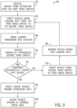
- FIG. 3 is a flow chart of an embodiment of a loading process 80 that may be utilized by the loading system 12. Accordingly, the following discussion may reference FIGS. 1-2 in parallel with FIG. 3 . Further, the following discussion references the progress of a particular ride vehicle 16 through the loading process 80.
- the first ride vehicle 16 may enter the loading zone 10 from the attraction path 18. More specifically, after traveling along the attraction path 18, the ride vehicle 16 may travel through the variable speed zone 28 and traverse the first track switch 24.
- the first ride vehicle 16 may be directed along the main portion 65 of the loading path 56 via the first track switch 24.
- the first track switch 24 may be in the first position by default to direct the first ride vehicle 16 in the first direction 58 from the variable speed zone 28.
- passengers present on the ride vehicle who have completed the attraction via travelling the attraction path 18 may unload from the first ride vehicle 16 while the first ride vehicle 16 continues to move along the main portion 65 of the loading path 56.
- passengers on the ride vehicles 16 may alternatively represent passengers in the loading stage who have not yet entered the attraction path 18 and who are in an incompletely loaded ride vehicle 16.
- ride operators may direct new passenger(s) to load into the first ride vehicle 16 while the first ride vehicle 16 continues to move along the main portion 65 of the loading path 56.
- the first ride vehicle 16 may continue along the loading path 56 from the first track switch 24 to the second track switch 26 while the passengers continue to load into the first ride vehicle 16.
- the first ride vehicle 16 may arrive at the second track switch 26. More specifically, at block 90, the first ride vehicle may approach the second track switch 26.
- a controller and/or operator will determine whether the passengers have successfully loaded into the first ride vehicle 16. For example, in some embodiments, as the first ride vehicle 16 travels along the main portion 65 of the loading path 56 (e.g., during blocks 84, 86, 88, and 90), an operator may observe the passenger unloading and loading the first ride vehicle 16.
- re-looping may be rules-based, such that fully-loaded vehicles are always moved onto the attraction path, empty vehicles are always re-looped, and partially loaded ride vehicles are either re-looped based on a signal indicative of passengers still attempting to load or moved onto the attraction based on a signal that all available passengers are loaded, even if the vehicle 16 has empty seats.
- the occupancy status may be a first status associated with a vehicle permitted to enter the attraction path or a second status associated with a vehicle designated to re-loop onto the loading path 56.
- Providing the load confirmation signal may include pressing a button on a control panel, utilizing a key, utilizing a short range communication device (e.g., an RFID tag), or any other suitable input.
- the load confirmation of the ride first vehicle 16 may be automatic and based on sensor detection of the passengers within the first ride vehicle 16.
- the controller may receive the load confirmation signal and, based on the load confirmation signal, adjust the second track switch 26 to the third position to cause the first ride vehicle 16 to travel in the third direction 62 to the attraction path 18. That is, generally, at block 92, if the passenger(s) have successfully loaded into the first ride vehicle 16 and the controller has received the load confirmation signal, the first ride vehicle 16 may be directed via the second track switch 26 toward the attraction path 18 (block 94). The first ride vehicle 16 may then travel along the attraction path 18 and eventually arrive back at the loading zone 10 (block 82).
- the first ride vehicle 16 may be directed along the loading path 56 from the second track switch 26 toward the first track switch 24 (e.g., along the secondary portion 66 of the loading path 56).
- the loading system 12 may direct the first ride vehicle 16 along the secondary portion 66 of the loading path 56 by default, such as if no input is received from the operator confirming load of the first ride vehicle 16.
- the second track switch 26 may be in the fourth position to direct the first ride vehicle 16 in the fourth direction 64 by default. If no load confirmation signal is received by the controller, the second track switch 26 may remain in the fourth position.
- the first ride vehicle 16 may once again be directed along the main portion 65 of the loading path 56 (block 84).
- a controller may operate to manage merging of the ride vehicles 16 to re-loop onto the main portion 65 of the loading path 56 into available spaces (block 98).
- the ride vehicles 16 moving along the main portion 65 of the loading path 56 may generally move along the loading path 56 at constant intervals. As such, assuming that each ride vehicle 16 is also directed along the attraction path 18 from the second track switch 26, the ride vehicles 16 may also generally travel along the attraction path 18 at constant intervals. However, as described in the embodiments of block 96, the first ride vehicle 16 may be directed from the second track switch 26 along the secondary portion 66 if passengers have not successfully loaded into the first ride vehicle 16, as opposed to being directed along the attraction path 18. Once the ride vehicle 16 traveling along the secondary portion 66 of the loading path 56 reaches the first track switch 24, the first track switch 24 may be placed in the second position to direct the ride vehicle 16 along the second direction 60 to continue along the main portion 65 of the loading path 56. That is, upon reaching the first track switch 24 from the secondary portion 66, the ride vehicle 16 may once again be directed along the loading path 56, as described in the embodiments of block 84.
- an extended interval (e.g., a gap, a bubble, a space), may occur between two adjacent ride vehicles 16 traveling along the attraction path 18 due to the first ride vehicle 16 having been disposed between the pair of adjacent ride vehicles 16 along the loading path 56, being directed to the first track switch 24 instead of to the attraction path 18.
- the extended interval between the pair of adjacent ride vehicles 16 may be normalized. That is, the interval between the adjacent ride vehicles 16 may become substantially uniform with the intervals between other ride vehicles 16 traveling through the variable speed zone 28. This may be accomplished by increasing or decreasing a speed of one or more ride vehicles 16 traveling through the variable speed zone 28.
- the adjustment in spacing may also be coordinated with re-looping of upcoming vehicles 16 from the secondary portion 66 of the loading path 56 into the main portion 65 of the loading path 56.
- a speed of a second ride vehicle 16 traveling through the variable speed zone 28 may be adjusted to create a space for the first ride vehicle 16 traveling along the secondary portion 66 toward the first track switch 24.
- the ride vehicles 16 may arrive to the variable speed zone 28 from the attraction path 18 before moving to the loading path 56. While in the variable speed zone 28, the ride vehicles 16 may travel at a nominal speed to transition to the loading path 56 at regular intervals.
- a speed of one or more vehicles 16 e.g., the second ride vehicle
- a speed of one or more vehicles 16 within the variable speed zone 28 may be adjusted to approximately double an interval between a pair of adjacent ride vehicles 16.
- the first ride vehicle 16 traveling from the second track switch 26 may be positioned between the pair of adjacent ride vehicles 16 of the variable speed zone 28 as the pair of adjacent ride vehicles 16 transitions to the loading path 56.
- the act of the first ride vehicle 16 being directed along the secondary portion 66 from the second track switch 24 may feed into the controller managing the merging in block 98.
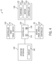
- FIG. 4 is a block diagram of the loading system 12.
- the loading system includes a turntable assembly 106 that drives rotation of the turntable 20 via a motor 108 and a turntable controller 110.
- the turntable controller 110 may be coupled to a central ride controller 120, and may communicate through a wireless network (e.g., wireless local area networks [WLAN], wireless wide area networks [WWAN], near field communication [NFC]) and/or through a wired network (e.g., local area networks [LAN], wide area networks [WAN]).
- the controller 120 includes a processor 124 and a memory 126. It should be understood that other disclosed components of the loading system 12 may also include a memory and processor and may operate to execute processor-based instructions stored in a memory.
- the central ride controller 120 may also control vehicle movement, variable vehicle movement (e.g., through the variable speed zone 28), merging from the secondary portion 66 of the loading path 56 during re-looping, and may communicate with the first track switch 24 and the second track switch 26 and their respective controllers 130, 132 to direct movement of the ride vehicles 16 between the attraction path 18 and the loading path 56.
- the controller 120 may receive a signal, or data, that one or more ride vehicles 16 approaching the second track switch 26 have an occupancy status associated with being moved onto the attraction path 18.
- the second track switch 26 receives a signal to switch to (or remain in) an attraction path position.
- the second track switch 26 receives a signal from the controller 120 to move to (or remain in) a position to re-loop the ride vehicle 16.
- the controller 120 may keep track of all vehicles 16 of the ride system 14 and their respective locations either on the loading path 56 or on the attraction path 18. Further, the controller 120 may control re-looping of empty vehicles 16 or entry into a maintenance or holding path to maintain a desired or fixed number of vehicles 16 in the attraction path 18. That is, the controller 120 may log entry of vehicles 18 onto the attraction path 18 and may prevent too many vehicles 16 from being on the attraction path 18 by directing vehicles 16 to re-loop until space is available.
- the central controller 120 may permit operator input via an operator interface 140, which may include a display 142.
- an operator may send one or more signals to the central controller 120 via the operator interface 140 to operate the loading system 12 as discussed herein.
- the embodiments disclosed herein include systems and methods configured to provide variable loading time for passengers loading into ride vehicles.
- the disclosed embodiments include an attraction with a loading zone having ride vehicles configured to rotate in conjunction with a turntable while passengers unload and load the ride vehicles.
- passengers have a set amount of time to load into the ride vehicles as the ride vehicles travel through the loading zone.
- the passenger and the ride vehicle may be re-looped to a start of the loading zone.
- the re-looping of the ride vehicle may be implemented without negatively affecting the progress of other ride vehicles through the loading zone or through the attraction.
Landscapes
- Engineering & Computer Science (AREA)
- Mechanical Engineering (AREA)
- Transportation (AREA)
- Motorcycle And Bicycle Frame (AREA)
- Escalators And Moving Walkways (AREA)
- Mobile Radio Communication Systems (AREA)
- Train Traffic Observation, Control, And Security (AREA)
- Specific Conveyance Elements (AREA)
- Electric Propulsion And Braking For Vehicles (AREA)
- Intermediate Stations On Conveyors (AREA)
Claims (15)
- Ein Attraktionsladesystem (12), das Folgendes umfasst:eine Drehscheibe (20), die dazu konfiguriert ist, um eine vertikale Achse (40) zu rotieren;ein Fahrgeschäftsgefährt (16), das dazu konfiguriert ist, entlang eines Ladepfades (56) zu fahren, der um einen Perimeter der Drehscheibe (20) herum angeordnet ist, wobei der Ladepfad (56) einen Hauptabschnitt (65) und einen Sekundärabschnitt (66) umfasst;eine erste Streckenweiche (24), die entlang des Ladepfades (56) an einer ersten radialen Position relativ zu der vertikalen Achse angeordnet ist und dazu konfiguriert ist, in einer ersten Position angeordnet zu werden, um das Fahrgeschäftsgefährt (16) von einem Attraktionspfad (18) zu dem Hauptabschnitt (65) des Ladepfades (56) zu führen, und dazu konfiguriert ist, in einer zweiten Position angeordnet zu werden, um das Fahrgeschäftsgefährt (16) von dem Sekundärabschnitt (66) des Ladepfades (56) zu dem Hauptabschnitt (65) des Ladepfades (56) zu führen; undeine zweite Streckenweiche (26), die entlang des Ladepfades (56) an einer zweiten radialen Position relativ zu der vertikalen Achse angeordnet ist und dazu konfiguriert ist, in einer dritten Position angeordnet zu werden, um das Fahrgeschäftsgefährt (16) von dem Hauptabschnitt (65) des Ladepfades (56) zu dem Attraktionspfad (18) führen, und dazu konfiguriert ist, in einer vierten Position angeordnet zu werden, um das Fahrgeschäftsgefährt (16) von dem Hauptabschnitt (65) des Ladepfades (26) zu dem Sekundärabschnitt (66) des Ladepfades (56) zu führen, wobei das Attraktionsladesystem (12) dazu konfiguriert ist, dem Fahrgeschäftsgefährt zu erlauben, entlang des Hauptabschnitts (65) von der ersten Streckenweiche (24) zu der zweiten Streckenweiche (26) zu fahren, und das Attraktionsladesystem (12) dazu konfiguriert ist, dem Fahrgeschäftsgefährt (16) zu erlauben, entlang des Sekundärabschnitts (66) von der zweiten Streckenweiche (26) zu der ersten Streckenweiche (24) zu fahren.
- Attraktionsladesystem (12) nach Anspruch 1, wobei das Fahrgeschäftsgefährt (16) entlang des Ladepfades (56) mit einer Geschwindigkeit fährt, die auf eine Rotationsgeschwindigkeit der Drehscheibe (20) ausgerichtet ist, sodass das Fahrgeschäftsgefährt (16) eine feste Distanz von einem bestimmten Punkt an einem Rand der Drehscheibe (20) aufrechterhält, während es entlang des Ladepfades (56) wird.
- Attraktionsladesystem (12) nach Anspruch 1, das eine feste Plattform umfasst, die koaxial innerhalb der Drehscheibe (20) positioniert ist und nicht mit der Drehscheibe (20) rotiert.
- Attraktionsladesystem (12) nach Anspruch 3, das einen Fahrgasteingangspfad umfasst, der mit der festen Plattform verbunden ist.
- Attraktionsladesystem (12) nach Anspruch 1, das eine Fahrgeschäftssteuereinheit (120) umfasst, die dazu konfiguriert ist, eine Geschwindigkeit des Fahrgeschäftsgefährts (16) in dem Attraktionspfad (18) zu steuern, um einen Abstand des Fahrgeschäftsgefährts (16) relativ zu einem anderen Fahrgeschäftsgefährt (16) anzupassen.
- Attraktionsladesystem (12) nach Anspruch 5, das eine variable Geschwindigkeitszone (28) umfasst, die an einem Ende des Attraktionspfades (18) angeordnet ist, wobei das Fahrgeschäftsgefährt (16) dazu konfiguriert ist, sich durch die variable Geschwindigkeitszone (28) zu bewegen, und wobei die erste Streckenweiche (24) dazu konfiguriert ist, in der ersten Position angeordnet zu werden, um das Fahrgeschäftsgefährt (16) von der variablen Geschwindigkeitszone (28) zu dem Hauptabschnitt (65) des Ladepfades (56) zu führen.
- Attraktionsladesystem (12) nach Anspruch 6, wobei die Fahrgeschäftssteuereinheit (120) dazu konfiguriert ist, die Geschwindigkeit des Fahrgeschäftsgefährts (16) zu steuern, während das Fahrgeschäftsgefährt (16) in der variablen Geschwindigkeitszone (28) ist, um den Abstand des Fahrgeschäftsgefährts (16) relativ zu einem zweiten Fahrgeschäftsgefährt (16) innerhalb der variablen Geschwindigkeitszone (28) anzupassen.
- Attraktionsladesystem (12) nach Anspruch 7, wobei die Fahrgeschäftssteuereinheit (120) dazu konfiguriert ist, innerhalb der variablen Geschwindigkeitszone (28) die Geschwindigkeit des Fahrgeschäftsgefährts (16) zu steuern, eine zweite Geschwindigkeit des zweiten Fahrgeschäftsgefährts (16) zu steuern, oder beides, um eine Distanz zwischen dem Fahrgeschäftsgefährt (16) und dem zweiten Fahrgeschäftsgefährt (16) innerhalb der variablen Geschwindigkeitszone (28) zu vergrößern.
- Attraktionsladesystem (12) nach Anspruch 7, wobei die Fahrgeschäftssteuereinheit (120) dazu konfiguriert ist, innerhalb der variablen Geschwindigkeitszone (28) die Geschwindigkeit des Fahrgeschäftsgefährts (16) zu steuern, eine zweite Geschwindigkeit des zweiten Fahrgeschäftsgefährts (16) zu steuern, oder beides, um eine Distanz zwischen dem Fahrgeschäftsgefährt und dem zweiten Fahrgeschäftsgefährt (16) innerhalb der variablen Geschwindigkeitszone (28) zu verringern.
- Attraktionsladesystem (12) nach Anspruch 1, das eine Fahrgeschäftssteuereinheit (120) umfasst, wobei die Fahrgeschäftssteuereinheit (120) dazu konfiguriert ist, ein mit dem Fahrgeschäftsgefährt (16) assoziiertes Ladungsbestätigungssignal zu empfangen, während das Fahrgeschäftsgefährt (16) entlang des Hauptabschnitts (65) des Ladepfades (56) fährt, und wobei die Fahrgeschäftssteuereinheit (120) dazu konfiguriert ist, die Position der zweiten Streckenweiche (26) basierend darauf anzupassen, ob die Fahrgeschäftssteuereinheit (120) das Ladebestätigungssignal empfängt.
- Attraktionsladesystem (12) nach Anspruch 10, wobei, nach Empfang des Bestätigungssignals, die Fahrgeschäftssteuereinheit (120) dazu konfiguriert ist, die zweite Streckenweiche (26) in die dritte Position zu positionieren, um das Fahrgeschäftsgefährt (16) von dem Hauptabschnitt (65) des Ladepfades (56) zu dem Attraktionspfad (18) zu führen.
- Attraktionsladesystem (12) nach Anspruch 10, wobei, bei Ausbleiben des Empfangs des Bestätigungssignals, die Fahrgeschäftssteuereinheit (120) dazu konfiguriert ist, die zweite Streckenweiche (26) in die vierte Position zu positionieren, um das Fahrgeschäftsfahrzeug (16) von dem Hauptabschnitt (65) des Ladepfades (56) zu dem Sekundärabschnitt (66) des Ladepfades (56) zu führen.
- Attraktionsladesystem (12) nach Anspruch 10, wobei das Ladungsbestätigungssignal basierend auf einer Sensordetektion von Fahrgästen innerhalb des Fahrgeschäftsgefährts (16) generiert wird.
- Attraktionsladesystem (12) nach Anspruch 1, das eine Fahrgeschäftssteuereinheit umfasst, wobei die Fahrgeschäftssteuereinheit (120) dazu konfiguriert ist, eine Geschwindigkeit des Fahrgeschäftsgefährts (16) entlang des Ladepfades (56) zu steuern, sodass die Geschwindigkeit des Fahrgeschäftsgefährts (16) entlang des Ladepfades (56) im Wesentlichen mit einer Rotationsgeschwindigkeit der Drehscheibe (20) übereinstimmt.
- Attraktionsladesystem (12) nach Anspruch 6, wobei die Fahrgeschäftssteuereinheit (120) dazu konfiguriert ist, eine Geschwindigkeit des Fahrgeschäftsgefährts (16) durch die variable Geschwindigkeitszone (28) basierend auf einer Präsenz eines zweiten Fahrgeschäftsgefährts (16), das entlang des Sekundärabschnitts (66) des Ladepfades (56) angeordnet ist, anzupassen.
Priority Applications (2)
| Application Number | Priority Date | Filing Date | Title |
|---|---|---|---|
| EP24190936.5A EP4427825B1 (de) | 2019-02-22 | 2020-02-18 | Ladedrehtellersysteme und -verfahren |
| EP26171008.1A EP4744749A2 (de) | 2019-02-22 | 2020-02-18 | Ladedrehtellersysteme und -verfahren |
Applications Claiming Priority (3)
| Application Number | Priority Date | Filing Date | Title |
|---|---|---|---|
| US201962809323P | 2019-02-22 | 2019-02-22 | |
| US16/741,400 US11584406B2 (en) | 2019-02-22 | 2020-01-13 | Loading turntable systems and methods |
| PCT/US2020/018540 WO2020172107A1 (en) | 2019-02-22 | 2020-02-18 | Loading turntable systems and methods |
Related Child Applications (1)
| Application Number | Title | Priority Date | Filing Date |
|---|---|---|---|
| EP24190936.5A Division EP4427825B1 (de) | 2019-02-22 | 2020-02-18 | Ladedrehtellersysteme und -verfahren |
Publications (2)
| Publication Number | Publication Date |
|---|---|
| EP3927445A1 EP3927445A1 (de) | 2021-12-29 |
| EP3927445B1 true EP3927445B1 (de) | 2024-07-31 |
Family
ID=72141452
Family Applications (3)
| Application Number | Title | Priority Date | Filing Date |
|---|---|---|---|
| EP24190936.5A Active EP4427825B1 (de) | 2019-02-22 | 2020-02-18 | Ladedrehtellersysteme und -verfahren |
| EP26171008.1A Pending EP4744749A2 (de) | 2019-02-22 | 2020-02-18 | Ladedrehtellersysteme und -verfahren |
| EP20714343.9A Active EP3927445B1 (de) | 2019-02-22 | 2020-02-18 | Ladedrehscheibensysteme und -verfahren |
Family Applications Before (2)
| Application Number | Title | Priority Date | Filing Date |
|---|---|---|---|
| EP24190936.5A Active EP4427825B1 (de) | 2019-02-22 | 2020-02-18 | Ladedrehtellersysteme und -verfahren |
| EP26171008.1A Pending EP4744749A2 (de) | 2019-02-22 | 2020-02-18 | Ladedrehtellersysteme und -verfahren |
Country Status (8)
| Country | Link |
|---|---|
| US (3) | US11584406B2 (de) |
| EP (3) | EP4427825B1 (de) |
| JP (2) | JP7551635B2 (de) |
| CN (3) | CN119056074A (de) |
| CA (1) | CA3129161A1 (de) |
| ES (1) | ES2988081T3 (de) |
| SG (1) | SG11202108134SA (de) |
| WO (1) | WO2020172107A1 (de) |
Families Citing this family (6)
| Publication number | Priority date | Publication date | Assignee | Title |
|---|---|---|---|---|
| US11584406B2 (en) * | 2019-02-22 | 2023-02-21 | Universal City Studios Llc | Loading turntable systems and methods |
| DE202020101431U1 (de) | 2020-03-16 | 2021-06-17 | Hereus Establishment | Fahrgeschäft |
| US12145631B2 (en) * | 2021-02-25 | 2024-11-19 | Disney Enterprises, Inc. | Station with infinite ingress and egress times for use in transportation systems |
| DE102021118616A1 (de) * | 2021-07-19 | 2023-01-19 | Mack Rides Ip Gmbh & Co. Kg | Vergnügungspark-Fahrgeschäft, insbesondere Achterbahn |
| KR20230020213A (ko) * | 2021-08-03 | 2023-02-10 | 현대자동차주식회사 | 모빌리티 환승 허브에서의 사용자 가이드 방법, 장치 및 시스템 |
| US12465865B2 (en) * | 2022-01-14 | 2025-11-11 | Universal City Studios Llc | Systems and methods for providing an image for an attraction system |
Family Cites Families (34)
| Publication number | Priority date | Publication date | Assignee | Title |
|---|---|---|---|---|
| US3404635A (en) | 1965-04-16 | 1968-10-08 | Walt Disney Prod | Boat amusement ride |
| US3865041A (en) * | 1973-04-16 | 1975-02-11 | Arrow Dev Co | Rotary platform vehicle passenger loading system |
| US4362456A (en) * | 1978-11-06 | 1982-12-07 | Barry Leonard D | Rotary loader and storage system |
| US4543886A (en) * | 1983-03-09 | 1985-10-01 | Intamin Inc. | Amusement ride including a rotating loading terminal |
| US4920890A (en) | 1988-08-05 | 1990-05-01 | Barber Gerald L | Amusement ride |
| US5197923A (en) * | 1991-09-30 | 1993-03-30 | Barber Gerald L | Floating and disembarking platform |
| US5583844A (en) | 1993-06-19 | 1996-12-10 | The Walt Disney Company | Programming device and method for controlling ride vehicles in an amusement attraction |
| JPH07108090A (ja) * | 1993-10-14 | 1995-04-25 | Sansei Yusoki Kk | 娯楽用乗物装置 |
| JP3394747B2 (ja) | 2000-07-19 | 2003-04-07 | 泉陽興業株式会社 | 娯楽用乗物装置 |
| AT409253B (de) | 2000-07-20 | 2002-07-25 | Innova Patent Gmbh | Anlage zur beförderung von personen und verfahren zum betrieb einer derartigen anlage |
| US7758435B2 (en) * | 2005-09-02 | 2010-07-20 | Water Ride Concepts, Inc. | Amusement water rides involving interactive user environments |
| US7484460B2 (en) * | 2005-09-30 | 2009-02-03 | Universal City Studios Lllp | Amusement ride track with motion base |
| CN101314357A (zh) | 2007-05-31 | 2008-12-03 | 上海市静安区青少年活动中心 | 一种列车不停站实现上下乘客的系统 |
| US7784405B2 (en) * | 2008-04-24 | 2010-08-31 | Disney Enterprises, Inc. | Vehicle transfer during operation of an omnimover ride |
| KR100988364B1 (ko) | 2008-09-23 | 2010-10-18 | (주)한국에이앤지 | 레일바이크용 턴테이블 장치 |
| US8960097B2 (en) | 2008-09-30 | 2015-02-24 | Disney Enterprises, Inc. | Dynamic loading system for a ride vehicle |
| DE202008016678U1 (de) * | 2008-12-17 | 2009-03-12 | Rofa Rosenheimer Förderanlagen GmbH | Weiche für eine Elektropalettenbahn |
| KR101062917B1 (ko) | 2010-11-19 | 2011-09-07 | (주)한국에이앤지 | 레일바이크용 분기장치 |
| US8517847B2 (en) | 2011-09-06 | 2013-08-27 | Disney Enterprises, Inc. | Omnitable ride system |
| US8578857B2 (en) | 2011-12-08 | 2013-11-12 | Disney Enterprises, Inc. | Amusement park ride with passenger loading separated from vehicle insertion into simulators |
| US9616349B2 (en) * | 2012-11-07 | 2017-04-11 | Oceaneering International, Inc. | Method of managing loading, unloading, and routing of trackless vehicles and system using the same |
| US9043056B2 (en) * | 2013-07-08 | 2015-05-26 | Disney Enterprises, Inc. | Method and system for using dynamic boundaries to manage the progression of ride vehicles that have rider control inputs |
| US9365364B1 (en) * | 2013-07-19 | 2016-06-14 | RWM Technologies, LLC | Controlled acceleration and transfer of items via a rotating platform |
| US10391410B2 (en) * | 2013-11-17 | 2019-08-27 | William J. Kitchen | Tracks for tower ride |
| US10556511B2 (en) * | 2015-05-04 | 2020-02-11 | Vekoma Rides Engineering B.V. | Amusement ride with speed trim system |
| US10099149B2 (en) * | 2015-10-02 | 2018-10-16 | Universal City Studios Llc | Amusement park ride tunnel |
| CA3041326C (en) * | 2016-10-27 | 2024-05-07 | Universal City Studios Llc | Systems and methods for ride control synchronization |
| US10835833B2 (en) | 2017-09-06 | 2020-11-17 | Universal City Studios Llc | System and method for track ride vehicle orientation |
| CN107715457B (zh) | 2017-11-10 | 2022-03-08 | 广东金马游乐股份有限公司 | 一种游乐设备的旋转式多发站系统 |
| CN107670286A (zh) | 2017-11-10 | 2018-02-09 | 中山市金马科技娱乐设备股份有限公司 | 一种游乐设备的换轨式多发站系统 |
| US11584406B2 (en) * | 2019-02-22 | 2023-02-21 | Universal City Studios Llc | Loading turntable systems and methods |
| US11524710B2 (en) * | 2019-03-29 | 2022-12-13 | Universal City Studios Llc | Loading turntable systems and methods |
| US10835832B2 (en) * | 2019-03-31 | 2020-11-17 | Universal City Studio LLC | Gap covering systems and methods for amusement park attractions |
| US12539889B2 (en) | 2019-08-27 | 2026-02-03 | Universal City Studios Llc | Gate systems and methods for rotating loading platform |
-
2020
- 2020-01-13 US US16/741,400 patent/US11584406B2/en active Active
- 2020-02-18 CN CN202411219396.9A patent/CN119056074A/zh active Pending
- 2020-02-18 JP JP2021549400A patent/JP7551635B2/ja active Active
- 2020-02-18 ES ES20714343T patent/ES2988081T3/es active Active
- 2020-02-18 EP EP24190936.5A patent/EP4427825B1/de active Active
- 2020-02-18 WO PCT/US2020/018540 patent/WO2020172107A1/en not_active Ceased
- 2020-02-18 CA CA3129161A patent/CA3129161A1/en active Pending
- 2020-02-18 CN CN202410702594.4A patent/CN118557977A/zh active Pending
- 2020-02-18 CN CN202080015712.4A patent/CN113423481B/zh active Active
- 2020-02-18 EP EP26171008.1A patent/EP4744749A2/de active Pending
- 2020-02-18 SG SG11202108134SA patent/SG11202108134SA/en unknown
- 2020-02-18 EP EP20714343.9A patent/EP3927445B1/de active Active
-
2023
- 2023-01-25 US US18/101,446 patent/US12060092B2/en active Active
-
2024
- 2024-07-25 US US18/784,414 patent/US20240375692A1/en active Pending
- 2024-09-04 JP JP2024152161A patent/JP2024177173A/ja active Pending
Also Published As
| Publication number | Publication date |
|---|---|
| CN113423481B (zh) | 2024-09-10 |
| JP2024177173A (ja) | 2024-12-19 |
| ES2988081T3 (es) | 2024-11-19 |
| CA3129161A1 (en) | 2020-08-27 |
| SG11202108134SA (en) | 2021-08-30 |
| CN113423481A (zh) | 2021-09-21 |
| EP4427825A3 (de) | 2024-12-18 |
| WO2020172107A1 (en) | 2020-08-27 |
| US20200269888A1 (en) | 2020-08-27 |
| US11584406B2 (en) | 2023-02-21 |
| EP3927445A1 (de) | 2021-12-29 |
| KR20210130181A (ko) | 2021-10-29 |
| CN119056074A (zh) | 2024-12-03 |
| CN118557977A (zh) | 2024-08-30 |
| EP4427825A2 (de) | 2024-09-11 |
| JP2022521329A (ja) | 2022-04-06 |
| JP7551635B2 (ja) | 2024-09-17 |
| EP4427825B1 (de) | 2026-04-08 |
| US20230166779A1 (en) | 2023-06-01 |
| US12060092B2 (en) | 2024-08-13 |
| EP4744749A2 (de) | 2026-05-20 |
| US20240375692A1 (en) | 2024-11-14 |
Similar Documents
| Publication | Publication Date | Title |
|---|---|---|
| EP4427825B1 (de) | Ladedrehtellersysteme und -verfahren | |
| EP3946660B1 (de) | Ladedrehscheibensysteme und -verfahren | |
| CN113613746B (zh) | 用于游乐园景点的间隙阻挡系统和方法 | |
| CN110650781B (zh) | 可变的载具乘坐设施转向器 | |
| EA039016B1 (ru) | Аттракцион, использующий безрельсовые транспортные средства, и способ его эксплуатации | |
| KR102964561B1 (ko) | 탑승 턴테이블 시스템 및 방법 | |
| HK40062083A (en) | Attraction loading system and method to load passengers into ride vehicles | |
| KR20260069807A (ko) | 탑승 턴테이블 시스템 및 방법 | |
| HK40120314A (zh) | 装载转台系统及方法 | |
| HK40062083B (zh) | 景观装载系统和将乘客装载到乘坐载运器中的方法 | |
| HK40116159A (zh) | 装载转台系统及方法 | |
| HK40063722A (en) | Loading turntable systems and methods | |
| HK40020540A (en) | Variable vehicle ride switch | |
| HK40020540B (en) | Variable vehicle ride switch | |
| HK40063688B (zh) | 用於游乐园景点的间隙阻挡系统和方法 |
Legal Events
| Date | Code | Title | Description |
|---|---|---|---|
| STAA | Information on the status of an ep patent application or granted ep patent |
Free format text: STATUS: UNKNOWN |
|
| STAA | Information on the status of an ep patent application or granted ep patent |
Free format text: STATUS: THE INTERNATIONAL PUBLICATION HAS BEEN MADE |
|
| PUAI | Public reference made under article 153(3) epc to a published international application that has entered the european phase |
Free format text: ORIGINAL CODE: 0009012 |
|
| STAA | Information on the status of an ep patent application or granted ep patent |
Free format text: STATUS: REQUEST FOR EXAMINATION WAS MADE |
|
| 17P | Request for examination filed |
Effective date: 20210916 |
|
| AK | Designated contracting states |
Kind code of ref document: A1 Designated state(s): AL AT BE BG CH CY CZ DE DK EE ES FI FR GB GR HR HU IE IS IT LI LT LU LV MC MK MT NL NO PL PT RO RS SE SI SK SM TR |
|
| DAV | Request for validation of the european patent (deleted) | ||
| DAX | Request for extension of the european patent (deleted) | ||
| GRAP | Despatch of communication of intention to grant a patent |
Free format text: ORIGINAL CODE: EPIDOSNIGR1 |
|
| STAA | Information on the status of an ep patent application or granted ep patent |
Free format text: STATUS: GRANT OF PATENT IS INTENDED |
|
| INTG | Intention to grant announced |
Effective date: 20230908 |
|
| RIN1 | Information on inventor provided before grant (corrected) |
Inventor name: RUSSELL, MICHAEL DAVID JR. Inventor name: BLUM, STEVEN C. Inventor name: ALARCON, LUIS CARLOS |
|
| P01 | Opt-out of the competence of the unified patent court (upc) registered |
Effective date: 20231020 |
|
| GRAJ | Information related to disapproval of communication of intention to grant by the applicant or resumption of examination proceedings by the epo deleted |
Free format text: ORIGINAL CODE: EPIDOSDIGR1 |
|
| STAA | Information on the status of an ep patent application or granted ep patent |
Free format text: STATUS: REQUEST FOR EXAMINATION WAS MADE |
|
| INTC | Intention to grant announced (deleted) | ||
| GRAP | Despatch of communication of intention to grant a patent |
Free format text: ORIGINAL CODE: EPIDOSNIGR1 |
|
| STAA | Information on the status of an ep patent application or granted ep patent |
Free format text: STATUS: GRANT OF PATENT IS INTENDED |
|
| INTG | Intention to grant announced |
Effective date: 20240228 |
|
| GRAS | Grant fee paid |
Free format text: ORIGINAL CODE: EPIDOSNIGR3 |
|
| GRAA | (expected) grant |
Free format text: ORIGINAL CODE: 0009210 |
|
| STAA | Information on the status of an ep patent application or granted ep patent |
Free format text: STATUS: THE PATENT HAS BEEN GRANTED |
|
| AK | Designated contracting states |
Kind code of ref document: B1 Designated state(s): AL AT BE BG CH CY CZ DE DK EE ES FI FR GB GR HR HU IE IS IT LI LT LU LV MC MK MT NL NO PL PT RO RS SE SI SK SM TR |
|
| REG | Reference to a national code |
Ref country code: CH Ref legal event code: EP Ref country code: GB Ref legal event code: FG4D |
|
| REG | Reference to a national code |
Ref country code: DE Ref legal event code: R096 Ref document number: 602020034838 Country of ref document: DE |
|
| REG | Reference to a national code |
Ref country code: IE Ref legal event code: FG4D |
|
| REG | Reference to a national code |
Ref country code: ES Ref legal event code: FG2A Ref document number: 2988081 Country of ref document: ES Kind code of ref document: T3 Effective date: 20241119 |
|
| REG | Reference to a national code |
Ref country code: LT Ref legal event code: MG9D |
|
| REG | Reference to a national code |
Ref country code: NL Ref legal event code: MP Effective date: 20240731 |
|
| PG25 | Lapsed in a contracting state [announced via postgrant information from national office to epo] |
Ref country code: PT Free format text: LAPSE BECAUSE OF FAILURE TO SUBMIT A TRANSLATION OF THE DESCRIPTION OR TO PAY THE FEE WITHIN THE PRESCRIBED TIME-LIMIT Effective date: 20241202 |
|
| PG25 | Lapsed in a contracting state [announced via postgrant information from national office to epo] |
Ref country code: PT Free format text: LAPSE BECAUSE OF FAILURE TO SUBMIT A TRANSLATION OF THE DESCRIPTION OR TO PAY THE FEE WITHIN THE PRESCRIBED TIME-LIMIT Effective date: 20241202 |
|
| PG25 | Lapsed in a contracting state [announced via postgrant information from national office to epo] |
Ref country code: NO Free format text: LAPSE BECAUSE OF FAILURE TO SUBMIT A TRANSLATION OF THE DESCRIPTION OR TO PAY THE FEE WITHIN THE PRESCRIBED TIME-LIMIT Effective date: 20241031 |
|
| PG25 | Lapsed in a contracting state [announced via postgrant information from national office to epo] |
Ref country code: NL Free format text: LAPSE BECAUSE OF FAILURE TO SUBMIT A TRANSLATION OF THE DESCRIPTION OR TO PAY THE FEE WITHIN THE PRESCRIBED TIME-LIMIT Effective date: 20240731 Ref country code: PL Free format text: LAPSE BECAUSE OF FAILURE TO SUBMIT A TRANSLATION OF THE DESCRIPTION OR TO PAY THE FEE WITHIN THE PRESCRIBED TIME-LIMIT Effective date: 20240731 Ref country code: GR Free format text: LAPSE BECAUSE OF FAILURE TO SUBMIT A TRANSLATION OF THE DESCRIPTION OR TO PAY THE FEE WITHIN THE PRESCRIBED TIME-LIMIT Effective date: 20241101 Ref country code: FI Free format text: LAPSE BECAUSE OF FAILURE TO SUBMIT A TRANSLATION OF THE DESCRIPTION OR TO PAY THE FEE WITHIN THE PRESCRIBED TIME-LIMIT Effective date: 20240731 |
|
| PG25 | Lapsed in a contracting state [announced via postgrant information from national office to epo] |
Ref country code: BG Free format text: LAPSE BECAUSE OF FAILURE TO SUBMIT A TRANSLATION OF THE DESCRIPTION OR TO PAY THE FEE WITHIN THE PRESCRIBED TIME-LIMIT Effective date: 20240731 |
|
| PG25 | Lapsed in a contracting state [announced via postgrant information from national office to epo] |
Ref country code: LV Free format text: LAPSE BECAUSE OF FAILURE TO SUBMIT A TRANSLATION OF THE DESCRIPTION OR TO PAY THE FEE WITHIN THE PRESCRIBED TIME-LIMIT Effective date: 20240731 |
|
| PG25 | Lapsed in a contracting state [announced via postgrant information from national office to epo] |
Ref country code: IS Free format text: LAPSE BECAUSE OF FAILURE TO SUBMIT A TRANSLATION OF THE DESCRIPTION OR TO PAY THE FEE WITHIN THE PRESCRIBED TIME-LIMIT Effective date: 20241130 |
|
| PG25 | Lapsed in a contracting state [announced via postgrant information from national office to epo] |
Ref country code: HR Free format text: LAPSE BECAUSE OF FAILURE TO SUBMIT A TRANSLATION OF THE DESCRIPTION OR TO PAY THE FEE WITHIN THE PRESCRIBED TIME-LIMIT Effective date: 20240731 |
|
| PG25 | Lapsed in a contracting state [announced via postgrant information from national office to epo] |
Ref country code: RS Free format text: LAPSE BECAUSE OF FAILURE TO SUBMIT A TRANSLATION OF THE DESCRIPTION OR TO PAY THE FEE WITHIN THE PRESCRIBED TIME-LIMIT Effective date: 20241031 |
|
| PG25 | Lapsed in a contracting state [announced via postgrant information from national office to epo] |
Ref country code: RS Free format text: LAPSE BECAUSE OF FAILURE TO SUBMIT A TRANSLATION OF THE DESCRIPTION OR TO PAY THE FEE WITHIN THE PRESCRIBED TIME-LIMIT Effective date: 20241031 Ref country code: PL Free format text: LAPSE BECAUSE OF FAILURE TO SUBMIT A TRANSLATION OF THE DESCRIPTION OR TO PAY THE FEE WITHIN THE PRESCRIBED TIME-LIMIT Effective date: 20240731 Ref country code: NO Free format text: LAPSE BECAUSE OF FAILURE TO SUBMIT A TRANSLATION OF THE DESCRIPTION OR TO PAY THE FEE WITHIN THE PRESCRIBED TIME-LIMIT Effective date: 20241031 Ref country code: NL Free format text: LAPSE BECAUSE OF FAILURE TO SUBMIT A TRANSLATION OF THE DESCRIPTION OR TO PAY THE FEE WITHIN THE PRESCRIBED TIME-LIMIT Effective date: 20240731 Ref country code: LV Free format text: LAPSE BECAUSE OF FAILURE TO SUBMIT A TRANSLATION OF THE DESCRIPTION OR TO PAY THE FEE WITHIN THE PRESCRIBED TIME-LIMIT Effective date: 20240731 Ref country code: IS Free format text: LAPSE BECAUSE OF FAILURE TO SUBMIT A TRANSLATION OF THE DESCRIPTION OR TO PAY THE FEE WITHIN THE PRESCRIBED TIME-LIMIT Effective date: 20241130 Ref country code: HR Free format text: LAPSE BECAUSE OF FAILURE TO SUBMIT A TRANSLATION OF THE DESCRIPTION OR TO PAY THE FEE WITHIN THE PRESCRIBED TIME-LIMIT Effective date: 20240731 Ref country code: GR Free format text: LAPSE BECAUSE OF FAILURE TO SUBMIT A TRANSLATION OF THE DESCRIPTION OR TO PAY THE FEE WITHIN THE PRESCRIBED TIME-LIMIT Effective date: 20241101 Ref country code: FI Free format text: LAPSE BECAUSE OF FAILURE TO SUBMIT A TRANSLATION OF THE DESCRIPTION OR TO PAY THE FEE WITHIN THE PRESCRIBED TIME-LIMIT Effective date: 20240731 Ref country code: BG Free format text: LAPSE BECAUSE OF FAILURE TO SUBMIT A TRANSLATION OF THE DESCRIPTION OR TO PAY THE FEE WITHIN THE PRESCRIBED TIME-LIMIT Effective date: 20240731 |
|
| PG25 | Lapsed in a contracting state [announced via postgrant information from national office to epo] |
Ref country code: RO Free format text: LAPSE BECAUSE OF FAILURE TO SUBMIT A TRANSLATION OF THE DESCRIPTION OR TO PAY THE FEE WITHIN THE PRESCRIBED TIME-LIMIT Effective date: 20240731 Ref country code: SM Free format text: LAPSE BECAUSE OF FAILURE TO SUBMIT A TRANSLATION OF THE DESCRIPTION OR TO PAY THE FEE WITHIN THE PRESCRIBED TIME-LIMIT Effective date: 20240731 Ref country code: DK Free format text: LAPSE BECAUSE OF FAILURE TO SUBMIT A TRANSLATION OF THE DESCRIPTION OR TO PAY THE FEE WITHIN THE PRESCRIBED TIME-LIMIT Effective date: 20240731 |
|
| PG25 | Lapsed in a contracting state [announced via postgrant information from national office to epo] |
Ref country code: EE Free format text: LAPSE BECAUSE OF FAILURE TO SUBMIT A TRANSLATION OF THE DESCRIPTION OR TO PAY THE FEE WITHIN THE PRESCRIBED TIME-LIMIT Effective date: 20240731 |
|
| PG25 | Lapsed in a contracting state [announced via postgrant information from national office to epo] |
Ref country code: CZ Free format text: LAPSE BECAUSE OF FAILURE TO SUBMIT A TRANSLATION OF THE DESCRIPTION OR TO PAY THE FEE WITHIN THE PRESCRIBED TIME-LIMIT Effective date: 20240731 |
|
| PG25 | Lapsed in a contracting state [announced via postgrant information from national office to epo] |
Ref country code: SK Free format text: LAPSE BECAUSE OF FAILURE TO SUBMIT A TRANSLATION OF THE DESCRIPTION OR TO PAY THE FEE WITHIN THE PRESCRIBED TIME-LIMIT Effective date: 20240731 |
|
| REG | Reference to a national code |
Ref country code: DE Ref legal event code: R097 Ref document number: 602020034838 Country of ref document: DE |
|
| PLBE | No opposition filed within time limit |
Free format text: ORIGINAL CODE: 0009261 |
|
| STAA | Information on the status of an ep patent application or granted ep patent |
Free format text: STATUS: NO OPPOSITION FILED WITHIN TIME LIMIT |
|
| 26N | No opposition filed |
Effective date: 20250501 |
|
| PG25 | Lapsed in a contracting state [announced via postgrant information from national office to epo] |
Ref country code: SE Free format text: LAPSE BECAUSE OF FAILURE TO SUBMIT A TRANSLATION OF THE DESCRIPTION OR TO PAY THE FEE WITHIN THE PRESCRIBED TIME-LIMIT Effective date: 20240731 |
|
| PG25 | Lapsed in a contracting state [announced via postgrant information from national office to epo] |
Ref country code: MC Free format text: LAPSE BECAUSE OF FAILURE TO SUBMIT A TRANSLATION OF THE DESCRIPTION OR TO PAY THE FEE WITHIN THE PRESCRIBED TIME-LIMIT Effective date: 20240731 |
|
| PG25 | Lapsed in a contracting state [announced via postgrant information from national office to epo] |
Ref country code: LU Free format text: LAPSE BECAUSE OF NON-PAYMENT OF DUE FEES Effective date: 20250218 |
|
| REG | Reference to a national code |
Ref country code: AT Ref legal event code: UEP Ref document number: 1707942 Country of ref document: AT Kind code of ref document: T Effective date: 20240731 |
|
| REG | Reference to a national code |
Ref country code: BE Ref legal event code: MM Effective date: 20250228 |
|
| PG25 | Lapsed in a contracting state [announced via postgrant information from national office to epo] |
Ref country code: BE Free format text: LAPSE BECAUSE OF NON-PAYMENT OF DUE FEES Effective date: 20250228 |
|
| PG25 | Lapsed in a contracting state [announced via postgrant information from national office to epo] |
Ref country code: IE Free format text: LAPSE BECAUSE OF NON-PAYMENT OF DUE FEES Effective date: 20250218 |
|
| REG | Reference to a national code |
Ref country code: CH Ref legal event code: U11 Free format text: ST27 STATUS EVENT CODE: U-0-0-U10-U11 (AS PROVIDED BY THE NATIONAL OFFICE) Effective date: 20260301 |
|
| PGFP | Annual fee paid to national office [announced via postgrant information from national office to epo] |
Ref country code: GB Payment date: 20260227 Year of fee payment: 7 |
|
| PGFP | Annual fee paid to national office [announced via postgrant information from national office to epo] |
Ref country code: ES Payment date: 20260302 Year of fee payment: 7 |
|
| PGFP | Annual fee paid to national office [announced via postgrant information from national office to epo] |
Ref country code: DE Payment date: 20260227 Year of fee payment: 7 |
|
| PGFP | Annual fee paid to national office [announced via postgrant information from national office to epo] |
Ref country code: AT Payment date: 20260227 Year of fee payment: 7 |
|
| PGFP | Annual fee paid to national office [announced via postgrant information from national office to epo] |
Ref country code: IT Payment date: 20260219 Year of fee payment: 7 |
|
| PGFP | Annual fee paid to national office [announced via postgrant information from national office to epo] |
Ref country code: FR Payment date: 20260225 Year of fee payment: 7 |
|
| PGFP | Annual fee paid to national office [announced via postgrant information from national office to epo] |
Ref country code: CH Payment date: 20260301 Year of fee payment: 7 |