EP3926948A1 - Video control device for vehicles, video system for vehicles, video control method, and program - Google Patents
Video control device for vehicles, video system for vehicles, video control method, and program Download PDFInfo
- Publication number
- EP3926948A1 EP3926948A1 EP19914810.7A EP19914810A EP3926948A1 EP 3926948 A1 EP3926948 A1 EP 3926948A1 EP 19914810 A EP19914810 A EP 19914810A EP 3926948 A1 EP3926948 A1 EP 3926948A1
- Authority
- EP
- European Patent Office
- Prior art keywords
- vehicle
- positions
- image
- video
- pickup apparatus
- Prior art date
- Legal status (The legal status is an assumption and is not a legal conclusion. Google has not performed a legal analysis and makes no representation as to the accuracy of the status listed.)
- Granted
Links
Images



Classifications
-
- G—PHYSICS
- G05—CONTROLLING; REGULATING
- G05D—SYSTEMS FOR CONTROLLING OR REGULATING NON-ELECTRIC VARIABLES
- G05D1/00—Control of position, course, altitude or attitude of land, water, air or space vehicles, e.g. using automatic pilots
- G05D1/0094—Control of position, course, altitude or attitude of land, water, air or space vehicles, e.g. using automatic pilots involving pointing a payload, e.g. camera, weapon, sensor, towards a fixed or moving target
-
- H—ELECTRICITY
- H04—ELECTRIC COMMUNICATION TECHNIQUE
- H04N—PICTORIAL COMMUNICATION, e.g. TELEVISION
- H04N5/00—Details of television systems
- H04N5/222—Studio circuitry; Studio devices; Studio equipment
-
- B—PERFORMING OPERATIONS; TRANSPORTING
- B60—VEHICLES IN GENERAL
- B60R—VEHICLES, VEHICLE FITTINGS, OR VEHICLE PARTS, NOT OTHERWISE PROVIDED FOR
- B60R1/00—Optical viewing arrangements; Real-time viewing arrangements for drivers or passengers using optical image capturing systems, e.g. cameras or video systems specially adapted for use in or on vehicles
- B60R1/20—Real-time viewing arrangements for drivers or passengers using optical image capturing systems, e.g. cameras or video systems specially adapted for use in or on vehicles
- B60R1/22—Real-time viewing arrangements for drivers or passengers using optical image capturing systems, e.g. cameras or video systems specially adapted for use in or on vehicles for viewing an area outside the vehicle, e.g. the exterior of the vehicle
- B60R1/23—Real-time viewing arrangements for drivers or passengers using optical image capturing systems, e.g. cameras or video systems specially adapted for use in or on vehicles for viewing an area outside the vehicle, e.g. the exterior of the vehicle with a predetermined field of view
- B60R1/27—Real-time viewing arrangements for drivers or passengers using optical image capturing systems, e.g. cameras or video systems specially adapted for use in or on vehicles for viewing an area outside the vehicle, e.g. the exterior of the vehicle with a predetermined field of view providing all-round vision, e.g. using omnidirectional cameras
-
- B—PERFORMING OPERATIONS; TRANSPORTING
- B60—VEHICLES IN GENERAL
- B60R—VEHICLES, VEHICLE FITTINGS, OR VEHICLE PARTS, NOT OTHERWISE PROVIDED FOR
- B60R1/00—Optical viewing arrangements; Real-time viewing arrangements for drivers or passengers using optical image capturing systems, e.g. cameras or video systems specially adapted for use in or on vehicles
- B60R1/20—Real-time viewing arrangements for drivers or passengers using optical image capturing systems, e.g. cameras or video systems specially adapted for use in or on vehicles
- B60R1/22—Real-time viewing arrangements for drivers or passengers using optical image capturing systems, e.g. cameras or video systems specially adapted for use in or on vehicles for viewing an area outside the vehicle, e.g. the exterior of the vehicle
- B60R1/28—Real-time viewing arrangements for drivers or passengers using optical image capturing systems, e.g. cameras or video systems specially adapted for use in or on vehicles for viewing an area outside the vehicle, e.g. the exterior of the vehicle with an adjustable field of view
-
- B—PERFORMING OPERATIONS; TRANSPORTING
- B60—VEHICLES IN GENERAL
- B60R—VEHICLES, VEHICLE FITTINGS, OR VEHICLE PARTS, NOT OTHERWISE PROVIDED FOR
- B60R11/00—Arrangements for holding or mounting articles, not otherwise provided for
- B60R11/02—Arrangements for holding or mounting articles, not otherwise provided for for radio sets, television sets, telephones, or the like; Arrangement of controls thereof
- B60R11/0229—Arrangements for holding or mounting articles, not otherwise provided for for radio sets, television sets, telephones, or the like; Arrangement of controls thereof for displays, e.g. cathodic tubes
-
- B—PERFORMING OPERATIONS; TRANSPORTING
- B60—VEHICLES IN GENERAL
- B60R—VEHICLES, VEHICLE FITTINGS, OR VEHICLE PARTS, NOT OTHERWISE PROVIDED FOR
- B60R11/00—Arrangements for holding or mounting articles, not otherwise provided for
- B60R11/04—Mounting of cameras operative during drive; Arrangement of controls thereof relative to the vehicle
-
- G—PHYSICS
- G05—CONTROLLING; REGULATING
- G05D—SYSTEMS FOR CONTROLLING OR REGULATING NON-ELECTRIC VARIABLES
- G05D1/00—Control of position, course, altitude or attitude of land, water, air or space vehicles, e.g. using automatic pilots
- G05D1/60—Intended control result
- G05D1/656—Interaction with payloads or external entities
- G05D1/689—Pointing payloads towards fixed or moving targets
-
- H—ELECTRICITY
- H04—ELECTRIC COMMUNICATION TECHNIQUE
- H04N—PICTORIAL COMMUNICATION, e.g. TELEVISION
- H04N13/00—Stereoscopic video systems; Multi-view video systems; Details thereof
- H04N13/20—Image signal generators
- H04N13/204—Image signal generators using stereoscopic image cameras
- H04N13/239—Image signal generators using stereoscopic image cameras using two two-dimensional [2D] image sensors having a relative position equal to or related to the interocular distance
-
- H—ELECTRICITY
- H04—ELECTRIC COMMUNICATION TECHNIQUE
- H04N—PICTORIAL COMMUNICATION, e.g. TELEVISION
- H04N13/00—Stereoscopic video systems; Multi-view video systems; Details thereof
- H04N13/20—Image signal generators
- H04N13/296—Synchronisation thereof; Control thereof
-
- H—ELECTRICITY
- H04—ELECTRIC COMMUNICATION TECHNIQUE
- H04N—PICTORIAL COMMUNICATION, e.g. TELEVISION
- H04N23/00—Cameras or camera modules comprising electronic image sensors; Control thereof
- H04N23/60—Control of cameras or camera modules
-
- H—ELECTRICITY
- H04—ELECTRIC COMMUNICATION TECHNIQUE
- H04N—PICTORIAL COMMUNICATION, e.g. TELEVISION
- H04N23/00—Cameras or camera modules comprising electronic image sensors; Control thereof
- H04N23/90—Arrangement of cameras or camera modules, e.g. multiple cameras in TV studios or sports stadiums
-
- H—ELECTRICITY
- H04—ELECTRIC COMMUNICATION TECHNIQUE
- H04N—PICTORIAL COMMUNICATION, e.g. TELEVISION
- H04N7/00—Television systems
- H04N7/18—Closed-circuit television [CCTV] systems, i.e. systems in which the video signal is not broadcast
-
- H—ELECTRICITY
- H04—ELECTRIC COMMUNICATION TECHNIQUE
- H04N—PICTORIAL COMMUNICATION, e.g. TELEVISION
- H04N7/00—Television systems
- H04N7/18—Closed-circuit television [CCTV] systems, i.e. systems in which the video signal is not broadcast
- H04N7/181—Closed-circuit television [CCTV] systems, i.e. systems in which the video signal is not broadcast for receiving images from a plurality of remote sources
-
- B—PERFORMING OPERATIONS; TRANSPORTING
- B60—VEHICLES IN GENERAL
- B60R—VEHICLES, VEHICLE FITTINGS, OR VEHICLE PARTS, NOT OTHERWISE PROVIDED FOR
- B60R11/00—Arrangements for holding or mounting articles, not otherwise provided for
- B60R2011/0001—Arrangements for holding or mounting articles, not otherwise provided for characterised by position
- B60R2011/0003—Arrangements for holding or mounting articles, not otherwise provided for characterised by position inside the vehicle
-
- B—PERFORMING OPERATIONS; TRANSPORTING
- B60—VEHICLES IN GENERAL
- B60R—VEHICLES, VEHICLE FITTINGS, OR VEHICLE PARTS, NOT OTHERWISE PROVIDED FOR
- B60R11/00—Arrangements for holding or mounting articles, not otherwise provided for
- B60R2011/0001—Arrangements for holding or mounting articles, not otherwise provided for characterised by position
- B60R2011/004—Arrangements for holding or mounting articles, not otherwise provided for characterised by position outside the vehicle
-
- B—PERFORMING OPERATIONS; TRANSPORTING
- B60—VEHICLES IN GENERAL
- B60R—VEHICLES, VEHICLE FITTINGS, OR VEHICLE PARTS, NOT OTHERWISE PROVIDED FOR
- B60R2300/00—Details of viewing arrangements using cameras and displays, specially adapted for use in a vehicle
- B60R2300/10—Details of viewing arrangements using cameras and displays, specially adapted for use in a vehicle characterised by the type of camera system used
- B60R2300/101—Details of viewing arrangements using cameras and displays, specially adapted for use in a vehicle characterised by the type of camera system used using cameras with adjustable capturing direction
-
- B—PERFORMING OPERATIONS; TRANSPORTING
- B60—VEHICLES IN GENERAL
- B60R—VEHICLES, VEHICLE FITTINGS, OR VEHICLE PARTS, NOT OTHERWISE PROVIDED FOR
- B60R2300/00—Details of viewing arrangements using cameras and displays, specially adapted for use in a vehicle
- B60R2300/10—Details of viewing arrangements using cameras and displays, specially adapted for use in a vehicle characterised by the type of camera system used
- B60R2300/105—Details of viewing arrangements using cameras and displays, specially adapted for use in a vehicle characterised by the type of camera system used using multiple cameras
-
- B—PERFORMING OPERATIONS; TRANSPORTING
- B60—VEHICLES IN GENERAL
- B60R—VEHICLES, VEHICLE FITTINGS, OR VEHICLE PARTS, NOT OTHERWISE PROVIDED FOR
- B60R2300/00—Details of viewing arrangements using cameras and displays, specially adapted for use in a vehicle
- B60R2300/30—Details of viewing arrangements using cameras and displays, specially adapted for use in a vehicle characterised by the type of image processing
-
- B—PERFORMING OPERATIONS; TRANSPORTING
- B60—VEHICLES IN GENERAL
- B60R—VEHICLES, VEHICLE FITTINGS, OR VEHICLE PARTS, NOT OTHERWISE PROVIDED FOR
- B60R2300/00—Details of viewing arrangements using cameras and displays, specially adapted for use in a vehicle
- B60R2300/80—Details of viewing arrangements using cameras and displays, specially adapted for use in a vehicle characterised by the intended use of the viewing arrangement
- B60R2300/8046—Details of viewing arrangements using cameras and displays, specially adapted for use in a vehicle characterised by the intended use of the viewing arrangement for replacing a rear-view mirror system
Definitions
- the present invention relates to a vehicle video control apparatus, a vehicle video system, a video control method, and a program, and in particular to a vehicle video control apparatus, a vehicle video system, a video control method, and a program for a vehicle equipped with a camera.
- a dashboard camera is configured to mainly shoot (i.e., take an image of) a view in the direction to the front/rear of a vehicle, i.e., in the traveling direction thereof.
- Patent Literature 1 discloses a dashboard camera that is equipped with a semi-spherical camera in order to also record the cause of an event or the like that occurs in the lateral direction of the vehicle in a parking monitoring mode. Further, in recent years, a vehicle has been equipped with electronic mirrors that display images obtained by cameras that shoot (i.e., take images of) views in the directions obliquely to the rear of the vehicle, instead of being equipped with side mirrors.
- Patent Literature 1 Japanese Unexamined Patent Application Publication No. 2018-196066
- a dashboard camera is expected to take images of views in the directions to the front/rear of a vehicle and record the taken images when the vehicle is being used, including when the vehicle is traveling. Meanwhile, it is required that a dashboard camera monitor not only the directions to the front/rear of the vehicle but also the directions to the left/right thereof when the vehicle is parked. However, it is very difficult to appropriately record video images of the outside of the vehicle with the semi-spherical camera disclosed in Patent Literature 1. Further, if another camera(s) for monitoring views in the left/right directions is installed in the vehicle, the cost of the vehicle may increase.
- the present invention provides a vehicle video control apparatus, a vehicle video system, a video control method, and a program capable of performing appropriate parking monitoring while preventing (or reducing) the increase in the cost.
- a vehicle video system includes:
- a video control method includes:
- a video control program causes a computer operating as a vehicle video control apparatus to perform:
- a vehicle video control apparatus capable of performing appropriate parking monitoring while preventing (or reducing) the increase in the cost.
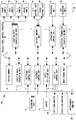
- Fig. 1 is a block diagram showing an example of a configuration of a vehicle video system according to the first embodiment.
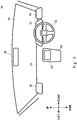
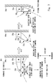
- Fig. 2 is a schematic view showing an example of a configuration of a part of a vehicle, which is equipped with the vehicle video system according to the first embodiment, in front of the driver's seat of the vehicle.
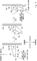
- Fig. 3 is a schematic diagram showing an example of operations performed by the vehicle video system according to the first embodiment.
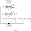
- Fig. 4 is a flowchart showing an example of operations performed by the vehicle video system according to the first embodiment.
- Fig. 2 is a view from the inside of a vehicle 50 toward the front thereof.
- Fig. 3 is a view of a left-side surface 50a of the vehicle 50 as viewed from above.
- the vehicle video system 100 includes a vehicle video control apparatus 20, a front camera 31, a rear camera 32, a left camera 33, a right camera 34, a left support part 35, a right support part 36, an operation unit 37, a GPS receiving unit 38, a recording unit 41, a sensor(s) 42, a left-side monitor 43, a right-side monitor 44, and an infotainment monitor 45.
- the vehicle video system 100 is installed in the vehicle 50 shown in Fig. 2 .
- Each of the front camera 31, the rear camera 32, the left camera 33, and the right camera 34 may be an image pickup apparatus. That is, the front camera 31 is a front image-pickup apparatus and the rear camera 32 is a rear image-pickup apparatus, Further, the left camera 33 is a left image-pickup apparatus and the right camera 34 is a right image-pickup apparatus.
- the front and rear cameras 31 and 32 may be cameras used in ordinary dashboard cameras. Further, the left and right cameras 33 and 34 may be cameras used in ordinary electronic mirrors.
- the front camera 31 is disposed on the front side of the vehicle 50 so as to face in the direction to the front of the vehicle 50, and shoots (i.e., takes an image of) a view in the direction to the front of the vehicle 50.
- the rear camera 32 is disposed on the rear side of the vehicle 50 so as to face in the direction to the rear of the vehicle 50, and shoots a view in the direction to the rear of the vehicle 50.
- Each of the front and rear cameras 31 and 32 outputs the taken video data to a shooting data acquisition unit 1.
- the left support part 35 includes a base 35a and an arm 35b.
- the base 35a is disposed on a left-side surface 50a of the vehicle 50.
- the arm 35b is disposed in the base 35a so as to be rotatable about a shaft 35c.
- the shaft 35c extends in a straight line in the vertical direction of the vehicle 50. Therefore, when the arm 35b rotates about the shaft 35c, it rotates on a horizontal plane of the vehicle 50.
- the left support part 35 rotationally moves the arm 35b based on a control signal received from a support control unit 2.
- the left camera 33 is disposed on the rear side of the tip of the arm 35b.
- the left camera 33 faces in a direction roughly perpendicular to the longitudinal direction of the arm 35b on the horizontal plane of the vehicle 50.
- the left camera 33 By rotating the arm 35b about the axis 35c, the left camera 33 is positioned at a first position or a second position.
- the longitudinal direction of the arm 35b is roughly perpendicular to the left-side surface 50a of the vehicle 50, the left camera 33 is positioned at the first position.
- the left camera 33 shoots a view in the direction to the left-rear of the vehicle 50.
- the vehicle 50 is being driven by a driver and hence the left camera 33 functions as an electronic mirror.
- the left camera 33 When the front side of the tip of the arm 35b faces the left-side surface 50a of the vehicle 50, the left camera 33 is at the second position.
- the left camera 33 shoots a view in the direction to the left of the vehicle 50.
- the left camera 33 outputs the taken video data to the shooting data acquisition unit 1.
- the vehicle 50 In most of the cases, when the left camera 33 is at the second position, the vehicle 50 is parked and hence the left camera 33 functions as a dashboard camera.
- the right support part 36 shown in Fig. 1 has a structure identical to that of the left support part 35, and is symmetrical to the left support part 35 with respect to the center line extending in the front/rear direction of the vehicle 50. Specifically, although details of the right support part 36 are not shown in the drawing, the right support part 36 has a structure that is obtained by replacing the reference numeral 35 with a reference numeral 36 in Fig. 3 and reversing (i.e., flipping over) the drawing in the left/right direction. Similar to the right support part 35, the right support part 36 includes a base 36a and an arm 36b. The base 36a is disposed on a right-side surface of the vehicle 50.
- the arm 36b is disposed in the base 36a so as to be rotatable about a shaft 36c.
- the shaft 36c extends in a straight line in the vertical direction of the vehicle 50. Therefore, when the arm 36b rotates about the shaft 36c, it rotates on a horizontal plane of the vehicle 50.
- the right support part 36 rotationally moves the arm 36b based on a control signal received from the support control unit 2.
- the right camera 34 is disposed on the rear side of the tip of the arm 36b of the right support part 36.
- the right camera 34 faces in a direction roughly perpendicular to the longitudinal direction of the arm 36b on the horizontal plane of the vehicle 50.
- the right camera 34 By rotating the arms 35b and 36b about the axes 35c and 36c, respectively, the right camera 34 as well as the left camera 33 is positioned at the first positions or at the second positions.
- the longitudinal directions of the arms 35b and 36b are roughly perpendicular to the right-side surface of the vehicle 50, the right camera 34 is positioned at the first position.
- the right camera 34 shoots a view in the direction to the right-rear of the vehicle 50.
- the right camera 34 When the front side of the tip of the arm 36b faces the right-side surface of the vehicle 50, the right camera 34 is positioned at the second position. The right camera 34 shoots a view in the direction to the right of the vehicle 50. The right camera 34 outputs the taken video data to the shooting data acquisition unit 1.
- the operation unit 37 serves as an interface that receives an operation input from an operator such as a driver, generates a signal indicating the received operation, and outputs the generated signal to an operation control unit 3.
- the GPS receiving unit 38 receives signals from a GPS (Global Positioning System) and outputs the received signals to a position information acquisition unit 4.
- GPS Global Positioning System
- the recording unit 41 stores shooting data that a recording control unit 7 has acquired from the shooting data acquisition unit 1.
- the recording unit 41 is, for example, a semiconductor memory device such as an EPROM (Erasable PROM), a flash ROM, a RAM (Random Access Memory); or a storage device such as a hard disk drive, an optical disk, a memory card, or an external storage device connected through a network.
- the recording unit 41 may be an external storage device that is wirelessly connected through a communication apparatus (not shown). Recodes are read from or added to the recording unit 41 by the recording control unit 7 and a playback control unit 8.
- the sensor 42 is a sensor(s) that measures a wide variety of objects to be measured as appropriate, and includes, for example, an acceleration sensor that measures an acceleration.
- the sensor 42 outputs measured measurement results to an event detection unit 9.
- the left-side monitor 43 is a display apparatus including, for example, a liquid crystal display or an OLED (Organic Light-Emitting Diode) display.
- the left-side monitor 43 displays a video image taken by the left camera 33 of the vehicle 50 based on a video signal output from a display control unit 10.
- the right-side monitor 44 is a display apparatus including, for example, a liquid crystal display or an OLED display.
- the right-side monitor 44 displays a video image taken by the right camera 34 of the vehicle 50 based on a video signal output from the display control unit 10.
- the infotainment monitor 45 is a display apparatus including, for example, a liquid crystal display or an OLED display.
- the infotainment monitor 45 displays a wide variety of images based on video signals output from the display control unit 10.
- the information monitor 45 may be a dedicated one for the vehicle video system 100, or may be one that is shared with, for example, other systems including a navigation system.
- the vehicle video control apparatus 20 includes the shooting data acquisition unit 1, the support control unit 2, the operation control unit 3, the position information acquisition unit 4, a buffer memory 5, a shooting data processing unit 6, the recording control unit 7, the playback control unit 8, the event detection unit 9, the display control unit 10, and a mode change unit 11.
- the vehicle video control apparatus 20 may be formed by a processor such as a CPU (Central Processing Unit). That is, the vehicle video control apparatus 20 can have functions as a computer. The vehicle video control apparatus 20 can execute a program stored in a storage device and thereby perform various types of processing. Further, the vehicle video control apparatus 20 implements the shooting data acquisition unit 1, the support control unit 2, the operation control unit 3, the position information acquisition unit 4, the shooting data processing unit 6, the recording control unit 7, the playback control unit 8, the event detection unit 9, the display control unit 10, and the mode change unit 11 by executing the program.
- a processor such as a CPU (Central Processing Unit). That is, the vehicle video control apparatus 20 can have functions as a computer.
- the vehicle video control apparatus 20 can execute a program stored in a storage device and thereby perform various types of processing. Further, the vehicle video control apparatus 20 implements the shooting data acquisition unit 1, the support control unit 2, the operation control unit 3, the position information acquisition unit 4, the shooting data processing unit 6, the recording control unit 7, the playback control unit 8, the event detection unit 9, the display control
- the storage device can include, for example, a DDR (Double Data Rate) memory, a Flash memory (flash memory), and the like as a part of the vehicle video control apparatus 20 or outside the vehicle video control apparatus 20. Further, the vehicle video system 100 may also include an EEPROM as part of the vehicle video control apparatus 20 or outside the vehicle video control apparatus 20. The storage device may be the recording unit 41.
- a DDR Double Data Rate
- Flash memory Flash memory
- the storage device may be the recording unit 41.
- each of the components of the vehicle video system 100 is not limited to one implemented by the program, and may be implemented by hardware, a combination of hardware and a program, or the like. Further, each of the components of the vehicle video control apparatus 20 may be implemented by using an integrated circuit that can be programmed by a user, such as an FPGA (field-programmable gate array) or a microcomputer. As described above, the vehicle video control apparatus 20 may implement the function of each of the components of the vehicle video control apparatus 20 by using the integrated circuit.
- an integrated circuit that can be programmed by a user
- the vehicle video control apparatus 20 may implement the function of each of the components of the vehicle video control apparatus 20 by using the integrated circuit.
- Each of the components constituting the vehicle video control apparatus 20, such as the shooting data acquisition unit 1, the support control unit 2, the operation control unit 3, the position information acquisition unit 4, the shooting data processing unit 6, the recording control unit 7, the playback control unit 8, the event detection unit 9, the display control unit 10, and the mode change unit 11 may be software or a module by which its processing is performed as the processor executes a program stored in the memory.
- each of the components constituting the vehicle video control apparatus 20 may be hardware such as a circuit or a chip.
- the shooting data acquisition unit 1 acquires video data generated by the front, rear, left, and right cameras 31, 32, 33 and 34. Data including such video data may be referred to as shooting data. In other words, the shooting data acquisition unit 1 may acquire shooting data from the front and rear cameras 31 and 32, and the left and right cameras 33 and 34. The shooting data may include audio data in addition to the video data.
- the operation control unit 3 generates operation input information based on a signal sent from the operation unit 37 and outputs the generated operation input information to the support control unit 2.
- the operation input information generated by the operation control unit 3 indicates, for example, an operation for switching the positions of the left and right support parts 35 and 36 to either the first positions or the second positions.
- the support control unit 2 acquires the operation input information from the operation control unit 3. Further, the support control unit 2 acquires power ON/OFF information indicating whether the power of the vehicle 50 is in an ON-state or in an OFF-state.
- the support control unit 2 may acquire the power ON/OFF information of the vehicle 50, for example, through a CAN (Controller Area Network). Further, the support control unit 2 may acquire, for example, various types of detection information sent from the various sensors 42 such as an acceleration sensor, and derive the power ON/OFF information of the vehicle 50 by performing calculation using the acquired various types of detection information.
- the operation input information and the power ON/OFF information indicate that the power of the vehicle 50 is in an ON-state, it means that the vehicle 50 is being driven by a driver.
- the operation input information and the power ON/OFF information indicate that the power of the vehicle 50 is in an OFF-state, the vehicle 50 is parked.
- the support control unit 2 sends a control signal corresponding to the operation input information and the power ON/OFF information sent from the operation control unit 3 to the left and right support parts 35 and 36.
- the support control unit 2 sends a control signal for positioning the left and right support parts 35 and 36 at the first positions.
- the support control unit 2 sends a control signal for positioning the left and right support parts 35 and 36 at the second positions.
- the position information acquisition unit 4 acquires signals received by the GPS receiving unit 38 and generates current position information of the vehicle 50.
- the buffer memory 5 temporarily stores, for example, output shooting data.
- the shooting data processing unit 6 generates shooting data in the form of a data file over a certain period from the shooting data temporarily stored in the buffer memory 5 by using an arbitrary method such as H.264 or MPEG-4 (Moving Picture Experts Group).
- the recording control unit 7 records the shooting data generated by the shooting data processing unit 6 in the recording unit 41 as overwritable data or write-protected data.
- the recording control unit 7 may record the shooting data in the recording unit 41 while specifying an address in a memory area in which data stored in the recording unit 41 can be overwritten or is prohibited from being overwritten.
- the recording control unit 7 may set, in a header or a payload of the shooting data, flag information indicating whether the shooting data can be overwritten or is prohibited from being overwritten.
- the recording control unit 7 records shooting data over a period that starts a predetermined time before the event and ends a predetermined time after the event in the recording unit 41 as write-protected data.
- the playback control unit 8 acquires the shooting data recorded in the recording section 41, and outputs video data obtained based on the acquired shooting data to the display control unit 10.
- the event detection unit 9 detects the occurrence of an event by using information output from the sensor 42. For example, when an acceleration detected by the sensor 42 that operates as an acceleration sensor exceeds a predetermined value, the event detection unit 9 detects that an event has occurred. The fact that the acceleration exceeds the predetermined value may also be expressed as that an impact corresponding to an accident has been exerted to the vehicle 50. Further, when the vehicle 50 is parked, the event detection unit 9 may detect a moving object from the video data acquired by the shooting data acquisition unit in addition to detecting an event based on an acceleration, and regard the detection of the moving object as the occurrence of an event. When the event detection unit 9 has detected the occurrence of an event, it outputs information indicating the occurrence of the event to the recording control unit 7. The information indicating the occurrence of the event includes a time when the event occurred. Further, the information indicating the occurrence of the event may include details of the event that has occurred.
- the display control unit 10 displays video images based on the video data acquired from the playback control unit 8, the buffer memory 5, and the like on the left-side monitor 43, the right-side monitor 44, the infotainment monitor 45, and the like.
- the display control unit 10 cuts out predetermined areas from the video data taken by the left and right cameras 33 and 34, and thereby generates video data that is displayed on the left-side and right-side monitors 43 and 44.
- the display control unit 10 cuts out areas of 60 to 90 degrees in the horizontal direction and 45 to 60 degrees in the vertical direction from the video data taken by the left and right cameras 33 and 34, and displays the cut-out areas on the left-side and right-side monitors 43 and 44, respectively.
- the mode change unit 11 makes the display control unit 10 display the video data taken by the left and right cameras 33 and 34 on the left-side and right-side monitors 43 and 44, respectively. Further, when the support control unit 2 has positioned the left and right support parts 35 and 36 at the second positions, the mode change unit 11 makes the recording control unit 7 use the video data taken by the left and right cameras 33 and 34 as monitoring information for monitoring the vehicle 50.
- the mode change unit 11 makes the left-side and right-side monitors 43 and 44, which are electronic mirrors, display images with which the driver checks areas in the directions to the left-rear and right-rear of the vehicle 50.
- the mode change unit 11 makes them as dashboard cameras and record video images of views in the directions to the left/right of the vehicle 50. That is, the mode change unit 11 switches the mode between an electronic-mirror mode and a dashboard-camera mode.
- Fig. 2 is a schematic view showing an example of a configuration of a part of a vehicle, which is equipped with the vehicle video system 100 according to the first embodiment, in front of the driver's seat of the vehicle.
- a video image is displayed on a landscape infotainment monitor 45 disposed in a center console 54.
- the left-side monitor 43, the right-side monitor 44, a dashboard 51, an instrument panel 52, a steering wheel 53, a windshield 55, a rear view monitor 56, etc. are arranged in front of the driver's seat inside the vehicle shown in Fig. 2 .
- the left-side monitor 43, the right-side monitor 44, and the infotainment monitor 45 are disposed at such positions that a driver can see them.
- the left-side monitor 43 is disposed on the left side of the dashboard 51 in the left/right direction of the vehicle 50.
- the right-side monitor 44 is disposed on the right side of the dashboard 51 in the left/right direction of the vehicle 50.
- the infotainment monitor 45 is disposed in the center console 54 positioned near the center of the dashboard 51 in the left/right direction.
- the instrument panel 52 is disposed in the dashboard 51 below the windshield 55, and displays a speedometer, an engine tachometer, and the like.
- the steering wheel 53 is used by a driver to perform a steering operation.
- the steering direction of the vehicle is changed according to the steering operation performed using the steering wheel 53.
- the rear view monitor 56 is a monitor with which the driver checks an area behind the vehicle, and is, for example, an electronic room mirror or a display apparatus including, for example, a liquid crystal display or an OLED display.
- the rear view monitor 56 may display a video image that is obtained by shooting a view in the direction to the rear of the vehicle 50 based on a video signal sent from the display control unit 10.
- the rear view monitor 56 is disposed at such a position that the driver can see it.
- the rear view monitor 56 according to this embodiment is disposed at the center in the left/right direction in the upper part of the windshield 55.
- the mode change unit 11 determines whether or not the operation control unit 3 has received an instruction to operate the left and right support parts 35 and 36 (Support part operation instruction determination step ST1).
- the mode change unit 11 determines whether or not the received instruction is an instruction indicating that the left and right support parts 35 and 36 should be moved from the first positions and positioned at the second positions (Second position positioning instruction determination step ST2).
- the mode change unit 11 switches the mode from an electronic-mirror mode to a dashboard-camera mode (Dashboard camera mode switching step ST3).
- the support control unit 2 sends a control signal to the left and right support parts 35 and 36, and thereby rotates the left and right support parts 35 and 36 from the first positions toward the left-side surface 50a of the vehicle 50 so that they get close to the left-side surface 50a, and elementally positions them at the second positions.
- the left and right support parts 35 and 36 are positioned at the second positions, video images taken by the left, right, front, and rear cameras 33, 34, 31, and 32 are recorded in the recording unit 41 as video images for the dashboard camera function.
- the recording control unit 7 records video image taken by the left and right cameras 33 and 34 in the recording unit 41 as video data of an angle of view ⁇ 1 (hereinafter also referred to as a view angle ⁇ 1).
- the view angle ⁇ 1 may be any angle as long as video images taken by the left and right cameras 33 and 34 have a width suitable as recorded video images of the dashboard cameras, and may be equal to the maximum angle of view of the left and right cameras 33 and 34.
- the view angle ⁇ 1 is, for example, 150 to 180 degrees in the horizontal direction and 90 to 120 degrees in the vertical direction.
- the video images recorded in the recording unit 41 can be used as monitoring information.
- the mode change unit 11 switches the mode from the dashboard-camera mode to the electronic-mirror mode (Electronic mirror mode switching step ST4).
- the left and right support parts 35 and 36 are positioned at the first positions. At the first positions, a video image taken by the left camera 33 is displayed on the left-side monitor 43, and a video image taken by the right camera 34 is displayed on the right-side monitor 44.
- the shooting data acquisition unit 1 acquires video images taken by the left and right cameras 33 and 34, and the display control unit 10 displays the acquired video images on the left-side and right-side monitors 43 and 44, respectively.
- the display control unit 10 displays video images that are obtained by cutting out parts of the view angles ⁇ 1 of the video images taken by the left and right cameras 33 and 34 on the left-side and right-side monitors 43 and 44, respectively.
- a view angle ⁇ 2 of display video images displayed on the left-side and right-side monitors 43 and 44 is, for example, 60 to 90 degrees in the horizontal direction.
- the view angle ⁇ 2 is preferably narrower than the view angle ⁇ 1.
- the view angle ⁇ 2 preferably has a width that is suitable when the display images are used for the electronic mirrors.
- the view angle ⁇ 2 is, for example, 60 to 90 degrees in the horizontal direction and 45 to 60 degrees in the vertical direction.
- video images taken by the front and rear cameras 31 and 32 are recorded in the recording unit 41 as video images for the dashboard camera function.
- shooting data that are obtained based on video images taken by the front and rear cameras 31 and 32 are temporarily stored in the buffer memory 5 and processed by the shooting data processing unit 6, so that a predetermined file(s) is generated.
- the shooting data processing unit 6 encodes and processes the acquired shooting data by a codec using an arbitrary method such as H.264 or MPEG-4.
- the predetermined file is a file in an arbitrary file format such as an MP4 format, and the time of the taken video image indicated by the predetermined file has an arbitrary length such as 60 seconds.
- the recording control unit 7 records the file generated by the shooting data processing unit 6 in the recording unit 41 in an overwritable state.
- the recording control unit 7 stores a video image that is obtained over a period that starts a predetermined time before the event and ends a predetermined time after the event in the recording unit 41 as write-protected data.
- video images taken by the left and right cameras 33 and 34 are used as images for electronic mirrors, and video images taken by the front and rear cameras 31 and 32 are used as video images of the dashboard cameras. Further, when the left and right support parts 35 and 36 are positioned at the second positions, video images taken by the front and rear cameras 31 and 32, in addition to the video images taken by the left and right cameras 33 and 34, are also used as video images of the dashboard cameras.
- the vehicle video system 100 it is possible to shoot a view in the direction to the front/rear of the vehicle 50 when the vehicle 50 is being used or is traveling, and to recode the taken video images. Meanwhile, when the vehicle 50 is parked, it is possible to shoot views in the directions to the left/right of the vehicle 50, in addition to the view in the directions to the front/rear thereof, and to recode the taken video images. It is possible to monitor areas in the directions to the left/right of the parked vehicle 50 by using the recorded video images as monitoring information.
- vehicle video system 100 it is possible to enable the vehicle video system 100 to achieve the above-described effects by using front and rear cameras 31 and 32 used in ordinary dashboard cameras or the like, and left and right cameras 33 and 34 used in ordinary electronic mirrors or the like. That is, it is possible to enable the vehicle video system 100 to achieve the above-described effects by using hardware configurations used in ordinary dashboard cameras and ordinary electronic mirrors without using additional hardware configurations, and thereby to reduce the increase in the cost.
- Fig. 5 is a block diagram showing an example of a configuration of a vehicle video system according to the second embodiment.
- Fig. 6 is a schematic view showing an example of operations performed by the vehicle video system according to the second embodiment, and is a view of a left-side surface 50a of a vehicle 50 as viewed from above.
- the vehicle video system 200 according to the second embodiment has a configuration identical to that of the vehicle video system 100 shown in Fig. 1 except for the left and right support parts, and the left and right cameras.
- the vehicle video system 200 includes a first left camera 33a, a second left camera 33b, a first right camera 34a, a second right camera 34b, a left support part 235, and a right support part 236.
- Each of the first left camera 33a, the second left camera 33b, the first right camera 34a, and the second right camera 34b may be an image pickup apparatus. That is, the first and second left cameras 33a and 33b constitute a left image-pickup apparatus, and the first and second right cameras 34a and 34b constitute a right image-pickup apparatus.
- Each of the first left, second left, first right, and second right cameras 33a, 33b, 34a, and 34b may be a camera used in an ordinary electronic mirror.
- the left support part 235 has a configuration identical to that of the left support part 35 shown in Figs. 1 and 3 except for operations performed by the arm 35b.
- the first left camera 33a is disposed on the rear side of the tip of the arm 35b.
- the second left camera 33b is disposed on the front side of the tip of the arm 35b.
- the first left camera 33a faces in a direction roughly perpendicular to the longitudinal direction of the arm 35b on a horizontal plane of the vehicle 50, and the second left camera 33b faces in a direction opposite to the direction in which the first left camera 33a faces.
- the first and second left cameras 33a and 33b are positioned at first positions or at second positions.
- the first and second left cameras 33a and 33b are positioned at the first positions.
- the first left camera 33a shoots a view in the direction to the left-rear of the vehicle 50.
- the first left camera 33a outputs the taken video data to the shooting data acquisition unit 1.
- the first and second left cameras 33a and 33b are positioned at the second positions.
- the second left camera 33b shoots a view in the direction to the left of the vehicle 50.
- the second left camera 33b outputs the taken video data to the shooting data acquisition unit 1.
- Each of the second left and second right cameras 33b and 34b is preferably be able to take a video image having a larger angle of view than that of the first left and first right cameras 33a and 34a.
- Each of the second left and second right cameras 33b and 34b is a camera that performs shooting with a view angle ⁇ 4 of, for example, 150 to 180 degrees in the horizontal direction and 90 to 120 degrees in the vertical direction.
- Each of the first left and first right cameras 33a and 34a is a camera that performs shooting with a view angle ⁇ 3 of, for example, 60 to 90 degrees in the horizontal direction and 45 to 60 degrees in the vertical direction.
- the view angle ⁇ 3 is preferably narrower than the view angle ⁇ 4.
- the view angle ⁇ 3 is preferably has a width that is suitable when video images taken by the first left and first right cameras 33a and 34a are used for images for electronic mirrors.
- the view angle ⁇ 4 is preferably has such a width that video images taken by the second left and second right cameras 33b and 34b are suitable as video images recorded by dashboard cameras.
- the right support part 236 shown in Fig. 5 has a configuration identical to that of the left support part 235, and is disposed so that they are symmetrical to each other with respect to the center line extending in the front/rear direction of the vehicle 50.
- the first right camera 34a has a configuration identical to that of the first left camera 33a, and is disposed so that they are symmetrical to each other with respect to the center line extending in the front/rear direction of the vehicle 50.
- the second right camera 34b has a configuration identical to that of the second left camera 33b, and is disposed so that they are symmetrical to each other with respect to the center line extending in the front/rear direction of the vehicle 50.
- An example of operations performed by the vehicle video system 200 will be described with reference to Figs. 4 and 6 .
- An example of operations performed by the vehicle video system 200 is the same as that of the above-described vehicle video system 100 except for the dashboard-camera mode switching step ST3 and the electronic-mirror mode switching step ST4.
- the support part operation instruction determination step ST1 and the second position positioning instruction determination step ST2 shown in Fig. 4 are preformed, and the process proceeds to the dashboard-camera mode switching step ST3 or the electronic-mirror mode switching step ST4.
- the support control unit 2 sends a control signal to the left and right support parts 235 and 236, and thereby positions the first left, second left, first right, and second right cameras 33a, 33b, 34a, and 34b at the second positions.
- Video images taken by the second left, second right, front, and rear cameras 33b, 34b, 31, and 32 are recorded in the recording unit 41 as video images for the dashboard camera function.
- the display control unit 10 records video images taken by the second left and second right cameras 33b and 34b in the recording unit 41.
- the support control unit 2 sends a control signal to the left and right support parts 235 and 236.
- the left and right support parts 235 and 236 position the first left, second left, first right, and second right cameras 33a, 33b, 34a, and 34b at the first positions.
- first left, second left, first right, and second right cameras 33a, 33b, 34a, and 34b are positioned at the first positions, video images taken by the first left camera 33a is displayed on the left-side monitor 43. Further, in such a case, a video image taken by the first right camera 34a is also displayed on the right-side monitor 44.
- the video images taken by the first left and first right cameras 33a and 34a have the view angle ⁇ 3 and are suitable as images used for electronic mirrors. Therefore, it is unnecessary to make the display control unit 10 of the vehicle video system 200 cut out predetermined areas from the video images taken by the first left and first right cameras 33a and 34a in order to generate display video data.
- the display control unit 10 of the vehicle video system 200 differs from the vehicle video system 200 shown in Fig. 1 , and may have a simpler configuration.
- the second left and second right cameras 33b and 34b do not need to perform shooting. Further, when the system is operating in the electronic-mirror mode, the second left and second right cameras 33b and 34b may be operated and their video images may be processed to recognize persons or other vehicles.
- the vehicle video system 200 may monitor an obstacle or the like present in front of the vehicle 50 based on information obtained by the aforementioned processing, and may notify the driver by using the left-side monitor 43, the right-side monitor 44, or the infotainment monitor 45 as required. Video images taken by the second left and second right cameras 33b and 34b may be recorded in the recording unit 41 as appropriate.
- the angle of view of video images taken by the front camera 31, and the second left and second right cameras 33b and 34b is wider than that of video images taken by the front camera 31 alone. Therefore, it is possible to monitor a large area in the direction to the front of the vehicle 50 by using video images taken by the front camera 31, and the second left and second right cameras 33b and 34b.
- the vehicle video system 200 it is possible to shoot a view in the direction to the front/rear of the vehicle 50 when the vehicle 50 is being used or is traveling, and to recode the taken video images as in the case of the vehicle video system 100. Meanwhile, when the vehicle 50 is parked, it is possible to shoot views in the directions to the left/right of the vehicle 50, in addition to the view in the directions to the front/rear thereof, and to recode the taken video images. It is possible to monitor areas in the directions to the left/right of the parked vehicle 50 by using the recorded video images as monitoring information.
- vehicle video system 200 it is possible to enable the vehicle video system 200 to achieve the above-described effects by using front and rear cameras 31 and 32 used in ordinary dashboard cameras or the like, and first left, second left, first right, and second right cameras 33a, 33b, 34a, and 34b used in ordinary electronic mirrors or the like. That is, it is possible to enable the vehicle video system 200 to achieve the above-described effects by using hardware configurations used in ordinary dashboard cameras and ordinary electronic mirrors without using additional hardware configurations, and thereby to reduce the increase in the cost.
- a vehicle video system 201 which is a modified example of the vehicle video system 200 will be described with reference to Fig. 7.
- Fig. 7 is a schematic view showing an example of operations performed by a modified example of a main part of the vehicle video system according to the second embodiment, and is a view of a left-side surface 50a of a vehicle 50 as viewed from above.
- the vehicle video system 201 has a configuration identical to that of the vehicle video system 200 shown in Fig. 5 except for a left camera 33c and a right camera (not shown).
- the left camera 33c may be an image-pickup apparatus.
- the left camera 33c may be a camera used in an ordinary electronic mirror or in an ordinary dashboard camera.
- the left camera 33c is disposed at the tip of an arm 35b so as to be rotatable about a shaft 33d.
- the shaft 33d extends in the vertical direction.
- the left camera 33c may be equipped with, for example, a power source such as a motor, and is rotated by this power source so as to face in a predetermined direction about the shaft 33d.
- the arm 35b shown in Fig. 7 rotates about the shaft 35c, so that the left camera 33c is positioned at a first position or at a second position.
- the left camera 33c is rotated about the shaft 35c and faces in a direction different from that of the arm 35b.
- the left camera 33c When the longitudinal direction of the arm 35b is roughly perpendicular to the left-side surface 50a of the vehicle 50, the left camera 33c is positioned at the first position. In this case, the left camera 33c shoots a view in the direction to the left-rear of the vehicle 50. The left camera 33c outputs the taken video data to the shooting data acquisition unit 1.
- the left camera 33c When the rear side of the tip of the arm 35b faces the left-side surface 50a of the vehicle 50, the left camera 33c is positioned at the second position. In this case, the left camera 33c shoots a view in the direction to the left of the vehicle 50. The left camera 33 outputs the taken video data to the shooting data acquisition unit 1.
- the right camera (not shown) has a configuration identical to that of the left camera 33c, and is disposed so that they are symmetrical to each other with respect to the center line extending in the front/rear direction of the vehicle 50.
- An example of operations performed by the vehicle video system 201 will be described.
- An example of operations performed by the vehicle video system 201 is the same as that of the above-described vehicle video system 200 except for the dashboard-camera mode switching step ST3 and the electronic-mirror mode switching step ST4.
- the support part operation instruction determination step ST1 and the second position positioning instruction determination step ST2 shown in Fig. 4 are preformed, and the process proceeds to the dashboard-camera mode switching step ST3 or the electronic-mirror mode switching step ST4.
- the support control unit 2 sends a control signal to the left and right support parts 235 and 236, and thereby positions the left camera 33c and the right camera (not shown) at the second positions. Further, the left camera 33c rotates about the shaft 33d as required and faces in the direction to the rear of the tip of the arm 35b. The right camera (not shown) also rotates in a manner similar to that of the left camera 33c and changes its direction.
- Video images taken by the left camera 33c, the right camera (not shown), the front camera 31, and the rear camera 32 are recorded in the recording unit 41 as video images for the dashboard camera function.
- the display control unit 10 records video images taken by the left camera 33c and the right camera (not shown) in the recording unit 41.
- the video images taken by the left camera 33c and the right camera (not shown) have a view angle ⁇ 1.
- the view angle ⁇ 1 has preferably such a width that video images taken by the left camera 33c and the right camera (not shown) are suitable as video images recorded by the dashboard cameras.
- the support control unit 2 sends a control signal to the left and right support parts 235 and 236.
- the left and right support parts 235 and 236 position the left camera 33c and the right camera (not shown) at the first positions. Further, the left camera 33c rotates about the shaft 33d as required and faces in the direction to the front of the tip of the arm 35b.
- the right camera (not shown) also rotates in a manner similar to that of the left camera 33c and changes its direction.
- a video image taken by the left camera 33c is displayed on the left-side monitor 43. Further, in such a case, a video image taken by the right camera (not shown) is also displayed on the right-side monitor 44.
- the display control unit 10 displays video images that are obtained by cutting out predetermined areas from the view angles ⁇ 1 of the video images taken by the left camera 33c and the right camera (not shown) on the left-side and right-side monitors 43 and 44.
- a view angle ⁇ 2 of display video images displayed on the left-side and right-side monitors 43 and 44 is, for example, 60 to 90 degrees in the horizontal direction.
- the view angle ⁇ 2 is preferably narrower than the view angle ⁇ 1.
- the view angle ⁇ 2 is preferably has a width that is suitable when the display images are used for images for electronic mirrors.
- the vehicle video system 201 it is possible to shoot a view in the direction to the front/rear of the vehicle 50 when the vehicle 50 is being used or is traveling, and to recode the taken video images as in the case of the vehicle video system 200. Meanwhile, when the vehicle 50 is parked, it is possible to shoot views in the directions to the left/right of the vehicle 50, in addition to the view in the directions to the front/rear thereof, and to recode the taken video images. It is possible to monitor areas in the directions to the left/right of the parked vehicle 50 by using the recorded video images as monitoring information.
- vehicle video system 201 it is possible to enable the vehicle video system 201 to achieve the above-described effects by using front and rear cameras 31 and 32 used in ordinary dashboard cameras or the like, and cameras used in ordinary electronic mirrors or dashboard cameras or the like. That is, it is possible to enable the vehicle video system 201 to achieve the above-described effects by using hardware configurations used in ordinary dashboard cameras and ordinary electronic mirrors without using additional hardware configurations, and thereby to reduce the increase in the cost.
- the number of left cameras and the number of right cameras are smaller than those in the vehicle video system 200.
- the configurations of the left and right cameras of the vehicle video system 201 are simpler than those of the vehicle video system 200.
- each of the vehicle video systems 100, 200 and 201 may have a hardware configuration described below.
- Fig. 8 is a diagram showing an example of a hardware configuration included in each of the vehicle video systems 100, 200 and 201.
- a vehicle video system 110 shown in Fig. 8 includes an interface 103 such as an interface for the operation unit 37, a processor 101, and a memory 102.
- the vehicle video control apparatus 20 described in each of the above-described embodiments is implemented by having the processor 101 load and execute a control program(s) stored in the memory 102. That is, this control program is a program for causing the processor 101 to function as the vehicle video control apparatus 20 shown in Fig. 1 or as a part thereof.
- This control program is a program for causing the vehicle video system 100 shown in Fig. 1 to perform processes performed in the vehicle video control apparatus 20 or in a part thereof.
- Non-transitory computer readable media include any type of tangible storage media.
- Examples of non-transitory computer readable media include magnetic storage media (such as floppy disks, magnetic tapes, hard disk drives, etc.), and optical magnetic storage media (e.g. magneto-optical disks).
- the examples include CD-ROM (Read Only Memory), CD-R, and CD-R/W.
- semiconductor memories such as mask ROM, PROM (programmable ROM), EPROM (erasable PROM), flash ROM, RAM (random access memory), etc.).
- the program may be provided to a computer using any type of transitory computer readable media.
- Examples of transitory computer readable media include electric signals, optical signals, and electromagnetic waves.
- Transitory computer readable media can provide the program to a computer via a wired communication line (e.g. electric wires, and optical fibers) or a wireless communication line.
- the present invention may be implemented in the form of an image control method as described above as a series of processes performed in the vehicle image systems 100, 200 and 201.
- the video control method includes first and second steps described below.
- the first step is a support control step of controlling a left support part and a right support part so that the left and right support parts can be positioned at first positions and at second positions, the left support part being configured to support a left image-pickup apparatus, the left image-pickup apparatus being disposed on a left side of a vehicle and configured to shoot a view to the left of the vehicle, the right support part being configured to support a right image-pickup apparatus, the right image-pickup apparatus being disposed on a right side of the vehicle and configured to shoot a view to the right of the vehicle, the first positions being positions at which the left image-pickup apparatus faces in a direction to the left-rear of the vehicle and the right image-pickup apparatus faces in a direction to the right-rear of the vehicle, and the second positions being positions at which the left image-pickup apparatus faces in a direction to the left of the vehicle and the right image-pickup apparatus faces in a direction to the right of the vehicle.
- the second step is a mode change step of displaying the video images taken by the left and right image-pickup apparatuses on a monitor when the left and right support parts are positioned at the first positions by the support control step, and using the video images taken by the left and right image-pickup apparatuses as monitoring information for monitoring the vehicle when the left and right support parts are disposed at the second positions, the monitor being configured so that a driver of the vehicle can see the monitor.
- control program is considered to be a video control program for causing a vehicle video system to perform such a video control method.
- the present invention can be used for, for example, a vehicle video control apparatus, a vehicle video system, a video control method, and a program for a vehicle equipped with a camera.
Landscapes
- Engineering & Computer Science (AREA)
- Multimedia (AREA)
- Signal Processing (AREA)
- Mechanical Engineering (AREA)
- Aviation & Aerospace Engineering (AREA)
- Radar, Positioning & Navigation (AREA)
- Remote Sensing (AREA)
- Physics & Mathematics (AREA)
- General Physics & Mathematics (AREA)
- Automation & Control Theory (AREA)
- Closed-Circuit Television Systems (AREA)
- Traffic Control Systems (AREA)
- Time Recorders, Dirve Recorders, Access Control (AREA)
- Studio Devices (AREA)
Abstract
Description
- The present invention relates to a vehicle video control apparatus, a vehicle video system, a video control method, and a program, and in particular to a vehicle video control apparatus, a vehicle video system, a video control method, and a program for a vehicle equipped with a camera.
- In general, a dashboard camera is configured to mainly shoot (i.e., take an image of) a view in the direction to the front/rear of a vehicle, i.e., in the traveling direction thereof.
-
Patent Literature 1 discloses a dashboard camera that is equipped with a semi-spherical camera in order to also record the cause of an event or the like that occurs in the lateral direction of the vehicle in a parking monitoring mode. Further, in recent years, a vehicle has been equipped with electronic mirrors that display images obtained by cameras that shoot (i.e., take images of) views in the directions obliquely to the rear of the vehicle, instead of being equipped with side mirrors. - Patent Literature 1:
Japanese Unexamined Patent Application Publication No. 2018-196066 - A dashboard camera is expected to take images of views in the directions to the front/rear of a vehicle and record the taken images when the vehicle is being used, including when the vehicle is traveling. Meanwhile, it is required that a dashboard camera monitor not only the directions to the front/rear of the vehicle but also the directions to the left/right thereof when the vehicle is parked. However, it is very difficult to appropriately record video images of the outside of the vehicle with the semi-spherical camera disclosed in
Patent Literature 1. Further, if another camera(s) for monitoring views in the left/right directions is installed in the vehicle, the cost of the vehicle may increase. - The present invention provides a vehicle video control apparatus, a vehicle video system, a video control method, and a program capable of performing appropriate parking monitoring while preventing (or reducing) the increase in the cost.
- A vehicle video control apparatus according to an embodiment includes:
- a support control unit configured to control a left support part and a right support part so that the left and right support parts can be positioned at first positions and at second positions, the left support part being configured to support a left image-pickup apparatus, the left image-pickup apparatus being disposed on a left side of a vehicle and configured to shoot a view to the left of the vehicle, the right support part being configured to support a right image-pickup apparatus, the right image-pickup apparatus being disposed on a right side of the vehicle and configured to shoot a view to the right of the vehicle, the first positions being positions at which the left image-pickup apparatus faces in a direction to the left-rear of the vehicle and the right image-pickup apparatus faces in a direction to the right-rear of the vehicle, and the second positions being positions at which the left image-pickup apparatus faces in a direction to the left of the vehicle and the right image-pickup apparatus faces in a direction to the right of the vehicle;
- a display control unit configured to display video images taken by the left and right image-pickup apparatuses on a monitor, the monitor being configured so that a driver of the vehicle can see the monitor;
- a recording control unit configured to use the video images taken by the left and right image-pickup apparatuses as monitoring information for monitoring the vehicle; and
- a mode change unit configured to make the display control unit display the video images taken by the left and right image-pickup apparatuses on the monitor, which the driver of the vehicle can see, when the left and right support parts are positioned at the first positions by the support control unit, and make the recording control unit use the video images taken by the left and right image-pickup apparatuses as the monitoring information for monitoring the vehicle when the left and right support parts are disposed at the second positions.
- Further, a vehicle video system according to an embodiment includes:
- the above-described vehicle video control apparatus; and
- the left and right image-pickup apparatuses, in which
- each of the left and right image-pickup apparatuses includes a first camera and a second camera,
- when the left and right support parts are positioned at the first positions, the first cameras face in directions to the left-rear and right-rear of the vehicle,
- when the left and right support parts are disposed at the second positions, the second cameras face in directions to the left and right of the vehicle, and
- an angle of view of taken video images taken by the second cameras is wider than that of taken video images taken by the first cameras.
- Further, a video control method according to ab embodiment includes:
- a support control step of controlling a left support part and a right support part so that the left and right support parts can be positioned at first positions and at second positions, the left support part being configured to support a left image-pickup apparatus, the left image-pickup apparatus being disposed on a left side of a vehicle and configured to shoot a view to the left of the vehicle, the right support part being configured to support a right image-pickup apparatus, the right image-pickup apparatus being disposed on a right side of the vehicle and configured to shoot a view to the right of the vehicle, the first positions being positions at which the left image-pickup apparatus faces in a direction to the left-rear of the vehicle and the right image-pickup apparatus faces in a direction to the right-rear of the vehicle, and the second positions being positions at which the left image-pickup apparatus faces in a direction to the left of the vehicle and the right image-pickup apparatus faces in a direction to the right of the vehicle; and
- a mode change step of displaying the video images taken by the left and right image-pickup apparatuses on a monitor when the left and right support parts are positioned at the first positions by the support control step, and using the video images taken by the left and right image-pickup apparatuses as monitoring information for monitoring the vehicle when the left and right support parts are disposed at the second positions, the monitor being configured so that a driver of the vehicle can see the monitor.
- Further, a video control program according to an embodiment causes a computer operating as a vehicle video control apparatus to perform:
- a support control step of controlling a left support part and a right support part so that the left and right support parts can be positioned at first positions and at second positions, the left support part being configured to support a left image-pickup apparatus, the left image-pickup apparatus being disposed on a left side of a vehicle and configured to shoot a view to the left of the vehicle, the right support part being configured to support a right image-pickup apparatus, the right image-pickup apparatus being disposed on a right side of the vehicle and configured to shoot a view to the right of the vehicle, the first positions being positions at which the left image-pickup apparatus faces in a direction to the left-rear of the vehicle and the right image-pickup apparatus faces in a direction to the right-rear of the vehicle, and the second positions being positions at which the left image-pickup apparatus faces in a direction to the left of the vehicle and the right image-pickup apparatus faces in a direction to the right of the vehicle; and
- a mode change step of displaying the video images taken by the left and right image-pickup apparatuses on a monitor when the left and right support parts are positioned at the first positions by the support control step, and using the video images taken by the left and right image-pickup apparatuses as monitoring information for monitoring the vehicle when the left and right support parts are disposed at the second positions, the monitor being configured so that a driver of the vehicle can see the monitor.
- According to the embodiment, it is possible to provide a vehicle video control apparatus, a vehicle video system, a video control method, and a program capable of performing appropriate parking monitoring while preventing (or reducing) the increase in the cost.
-
-
Fig. 1 is a block diagram showing an example of a configuration of a vehicle video system according to a first embodiment; -
Fig. 2 is a schematic view showing an example of a configuration of a part of a vehicle, which is equipped with the vehicle video system according to the first embodiment, in front of the driver's seat of the vehicle; -
Fig. 3 is a schematic diagram showing an example of operations performed by the vehicle video system according to the first embodiment; -
Fig. 4 is a flowchart showing an example of operations performed by the vehicle video system according to the first embodiment; -
Fig. 5 is a block diagram showing an example of a configuration of a vehicle video system according to a second embodiment; -
Fig. 6 is a schematic diagram showing an example of operations performed by the vehicle video system according to the second embodiment; -
Fig. 7 is a schematic diagram showing an example of operations performed by a modified example of the vehicle video system according to the second embodiment; and -
Fig. 8 shows an example of a hardware configuration included in a vehicle video system. - A first embodiment will be described hereinafter with reference to
Figs. 1 to 4 .Fig. 1 is a block diagram showing an example of a configuration of a vehicle video system according to the first embodiment.Fig. 2 is a schematic view showing an example of a configuration of a part of a vehicle, which is equipped with the vehicle video system according to the first embodiment, in front of the driver's seat of the vehicle.Fig. 3 is a schematic diagram showing an example of operations performed by the vehicle video system according to the first embodiment.Fig. 4 is a flowchart showing an example of operations performed by the vehicle video system according to the first embodiment. - Note that, needless to say, three-dimensional orthogonal coordinate systems shown in
Fig. 2 and other figures indicate a vertical direction, a left/right direction, and a front/rear direction, and are shown solely for a purpose of explaining positional relations among components. Normally, throughout the drawings, an upward direction is a vertically upward direction, and a plane extending in the longitudinal and left/right directions is a horizontal plane.Fig. 2 is a view from the inside of avehicle 50 toward the front thereof.Fig. 3 is a view of a left-side surface 50a of thevehicle 50 as viewed from above. - As shown in
Fig. 1 , thevehicle video system 100 includes a vehiclevideo control apparatus 20, afront camera 31, arear camera 32, aleft camera 33, aright camera 34, aleft support part 35, aright support part 36, anoperation unit 37, aGPS receiving unit 38, arecording unit 41, a sensor(s) 42, a left-side monitor 43, a right-side monitor 44, and aninfotainment monitor 45. Thevehicle video system 100 is installed in thevehicle 50 shown inFig. 2 . - Each of the
front camera 31, therear camera 32, theleft camera 33, and theright camera 34 may be an image pickup apparatus. That is, thefront camera 31 is a front image-pickup apparatus and therear camera 32 is a rear image-pickup apparatus, Further, theleft camera 33 is a left image-pickup apparatus and theright camera 34 is a right image-pickup apparatus. The front andrear cameras right cameras - The
front camera 31 is disposed on the front side of thevehicle 50 so as to face in the direction to the front of thevehicle 50, and shoots (i.e., takes an image of) a view in the direction to the front of thevehicle 50. Therear camera 32 is disposed on the rear side of thevehicle 50 so as to face in the direction to the rear of thevehicle 50, and shoots a view in the direction to the rear of thevehicle 50. Each of the front andrear cameras data acquisition unit 1. - As shown in
Fig. 3 , theleft support part 35 includes abase 35a and anarm 35b. Thebase 35a is disposed on a left-side surface 50a of thevehicle 50. Thearm 35b is disposed in thebase 35a so as to be rotatable about ashaft 35c. Theshaft 35c extends in a straight line in the vertical direction of thevehicle 50. Therefore, when thearm 35b rotates about theshaft 35c, it rotates on a horizontal plane of thevehicle 50. Theleft support part 35 rotationally moves thearm 35b based on a control signal received from asupport control unit 2. - The
left camera 33 is disposed on the rear side of the tip of thearm 35b. Theleft camera 33 faces in a direction roughly perpendicular to the longitudinal direction of thearm 35b on the horizontal plane of thevehicle 50. - By rotating the
arm 35b about theaxis 35c, theleft camera 33 is positioned at a first position or a second position. When the longitudinal direction of thearm 35b is roughly perpendicular to the left-side surface 50a of thevehicle 50, theleft camera 33 is positioned at the first position. Theleft camera 33 shoots a view in the direction to the left-rear of thevehicle 50. In most of the cases, when theleft camera 33 is at the first position, thevehicle 50 is being driven by a driver and hence theleft camera 33 functions as an electronic mirror. - When the front side of the tip of the
arm 35b faces the left-side surface 50a of thevehicle 50, theleft camera 33 is at the second position. Theleft camera 33 shoots a view in the direction to the left of thevehicle 50. Theleft camera 33 outputs the taken video data to the shootingdata acquisition unit 1. In most of the cases, when theleft camera 33 is at the second position, thevehicle 50 is parked and hence theleft camera 33 functions as a dashboard camera. - The
right support part 36 shown inFig. 1 has a structure identical to that of theleft support part 35, and is symmetrical to theleft support part 35 with respect to the center line extending in the front/rear direction of thevehicle 50. Specifically, although details of theright support part 36 are not shown in the drawing, theright support part 36 has a structure that is obtained by replacing thereference numeral 35 with areference numeral 36 inFig. 3 and reversing (i.e., flipping over) the drawing in the left/right direction. Similar to theright support part 35, theright support part 36 includes a base 36a and an arm 36b. The base 36a is disposed on a right-side surface of thevehicle 50. The arm 36b is disposed in the base 36a so as to be rotatable about a shaft 36c. The shaft 36c extends in a straight line in the vertical direction of thevehicle 50. Therefore, when the arm 36b rotates about the shaft 36c, it rotates on a horizontal plane of thevehicle 50. Theright support part 36 rotationally moves the arm 36b based on a control signal received from thesupport control unit 2. - The
right camera 34 is disposed on the rear side of the tip of the arm 36b of theright support part 36. Theright camera 34 faces in a direction roughly perpendicular to the longitudinal direction of the arm 36b on the horizontal plane of thevehicle 50. - By rotating the
arms 35b and 36b about theaxes 35c and 36c, respectively, theright camera 34 as well as theleft camera 33 is positioned at the first positions or at the second positions. When the longitudinal directions of thearms 35b and 36b are roughly perpendicular to the right-side surface of thevehicle 50, theright camera 34 is positioned at the first position. Theright camera 34 shoots a view in the direction to the right-rear of thevehicle 50. - When the front side of the tip of the arm 36b faces the right-side surface of the
vehicle 50, theright camera 34 is positioned at the second position. Theright camera 34 shoots a view in the direction to the right of thevehicle 50. Theright camera 34 outputs the taken video data to the shootingdata acquisition unit 1. - The
operation unit 37 serves as an interface that receives an operation input from an operator such as a driver, generates a signal indicating the received operation, and outputs the generated signal to anoperation control unit 3. - The
GPS receiving unit 38 receives signals from a GPS (Global Positioning System) and outputs the received signals to a positioninformation acquisition unit 4. - The
recording unit 41 stores shooting data that arecording control unit 7 has acquired from the shootingdata acquisition unit 1. Therecording unit 41 is, for example, a semiconductor memory device such as an EPROM (Erasable PROM), a flash ROM, a RAM (Random Access Memory); or a storage device such as a hard disk drive, an optical disk, a memory card, or an external storage device connected through a network. Therecording unit 41 may be an external storage device that is wirelessly connected through a communication apparatus (not shown). Recodes are read from or added to therecording unit 41 by therecording control unit 7 and aplayback control unit 8. - The
sensor 42 is a sensor(s) that measures a wide variety of objects to be measured as appropriate, and includes, for example, an acceleration sensor that measures an acceleration. Thesensor 42 outputs measured measurement results to anevent detection unit 9. - The left-
side monitor 43 is a display apparatus including, for example, a liquid crystal display or an OLED (Organic Light-Emitting Diode) display. The left-side monitor 43 displays a video image taken by theleft camera 33 of thevehicle 50 based on a video signal output from adisplay control unit 10. - The right-
side monitor 44 is a display apparatus including, for example, a liquid crystal display or an OLED display. The right-side monitor 44 displays a video image taken by theright camera 34 of thevehicle 50 based on a video signal output from thedisplay control unit 10. - The infotainment monitor 45 is a display apparatus including, for example, a liquid crystal display or an OLED display. The infotainment monitor 45 displays a wide variety of images based on video signals output from the
display control unit 10. The information monitor 45 may be a dedicated one for thevehicle video system 100, or may be one that is shared with, for example, other systems including a navigation system. - As shown in
Fig. 1 , the vehiclevideo control apparatus 20 includes the shootingdata acquisition unit 1, thesupport control unit 2, theoperation control unit 3, the positioninformation acquisition unit 4, a buffer memory 5, a shootingdata processing unit 6, therecording control unit 7, theplayback control unit 8, theevent detection unit 9, thedisplay control unit 10, and amode change unit 11. - The vehicle
video control apparatus 20 may be formed by a processor such as a CPU (Central Processing Unit). That is, the vehiclevideo control apparatus 20 can have functions as a computer. The vehiclevideo control apparatus 20 can execute a program stored in a storage device and thereby perform various types of processing. Further, the vehiclevideo control apparatus 20 implements the shootingdata acquisition unit 1, thesupport control unit 2, theoperation control unit 3, the positioninformation acquisition unit 4, the shootingdata processing unit 6, therecording control unit 7, theplayback control unit 8, theevent detection unit 9, thedisplay control unit 10, and themode change unit 11 by executing the program. - The storage device can include, for example, a DDR (Double Data Rate) memory, a Flash memory (flash memory), and the like as a part of the vehicle
video control apparatus 20 or outside the vehiclevideo control apparatus 20. Further, thevehicle video system 100 may also include an EEPROM as part of the vehiclevideo control apparatus 20 or outside the vehiclevideo control apparatus 20. The storage device may be therecording unit 41. - Note that each of the components of the
vehicle video system 100 is not limited to one implemented by the program, and may be implemented by hardware, a combination of hardware and a program, or the like. Further, each of the components of the vehiclevideo control apparatus 20 may be implemented by using an integrated circuit that can be programmed by a user, such as an FPGA (field-programmable gate array) or a microcomputer. As described above, the vehiclevideo control apparatus 20 may implement the function of each of the components of the vehiclevideo control apparatus 20 by using the integrated circuit. - Each of the components constituting the vehicle
video control apparatus 20, such as the shootingdata acquisition unit 1, thesupport control unit 2, theoperation control unit 3, the positioninformation acquisition unit 4, the shootingdata processing unit 6, therecording control unit 7, theplayback control unit 8, theevent detection unit 9, thedisplay control unit 10, and themode change unit 11 may be software or a module by which its processing is performed as the processor executes a program stored in the memory. Alternatively, each of the components constituting the vehiclevideo control apparatus 20 may be hardware such as a circuit or a chip. - The shooting
data acquisition unit 1 acquires video data generated by the front, rear, left, andright cameras data acquisition unit 1 may acquire shooting data from the front andrear cameras right cameras - The
operation control unit 3 generates operation input information based on a signal sent from theoperation unit 37 and outputs the generated operation input information to thesupport control unit 2. The operation input information generated by theoperation control unit 3 indicates, for example, an operation for switching the positions of the left andright support parts - The
support control unit 2 acquires the operation input information from theoperation control unit 3. Further, thesupport control unit 2 acquires power ON/OFF information indicating whether the power of thevehicle 50 is in an ON-state or in an OFF-state. Thesupport control unit 2 may acquire the power ON/OFF information of thevehicle 50, for example, through a CAN (Controller Area Network). Further, thesupport control unit 2 may acquire, for example, various types of detection information sent from thevarious sensors 42 such as an acceleration sensor, and derive the power ON/OFF information of thevehicle 50 by performing calculation using the acquired various types of detection information. When the operation input information and the power ON/OFF information indicate that the power of thevehicle 50 is in an ON-state, it means that thevehicle 50 is being driven by a driver. When the operation input information and the power ON/OFF information indicate that the power of thevehicle 50 is in an OFF-state, thevehicle 50 is parked. - The
support control unit 2 sends a control signal corresponding to the operation input information and the power ON/OFF information sent from theoperation control unit 3 to the left andright support parts vehicle 50 is in an ON-state, thesupport control unit 2 sends a control signal for positioning the left andright support parts vehicle 50 is in an OFF-state, thesupport control unit 2 sends a control signal for positioning the left andright support parts - The position
information acquisition unit 4 acquires signals received by theGPS receiving unit 38 and generates current position information of thevehicle 50. The buffer memory 5 temporarily stores, for example, output shooting data. - The shooting
data processing unit 6 generates shooting data in the form of a data file over a certain period from the shooting data temporarily stored in the buffer memory 5 by using an arbitrary method such as H.264 or MPEG-4 (Moving Picture Experts Group). - The
recording control unit 7 records the shooting data generated by the shootingdata processing unit 6 in therecording unit 41 as overwritable data or write-protected data. For example, therecording control unit 7 may record the shooting data in therecording unit 41 while specifying an address in a memory area in which data stored in therecording unit 41 can be overwritten or is prohibited from being overwritten. Alternatively, therecording control unit 7 may set, in a header or a payload of the shooting data, flag information indicating whether the shooting data can be overwritten or is prohibited from being overwritten. When theevent detection unit 9 outputs information indicating that an event has occurred to therecording control unit 7, therecording control unit 7 records shooting data over a period that starts a predetermined time before the event and ends a predetermined time after the event in therecording unit 41 as write-protected data. - The
playback control unit 8 acquires the shooting data recorded in therecording section 41, and outputs video data obtained based on the acquired shooting data to thedisplay control unit 10. - The
event detection unit 9 detects the occurrence of an event by using information output from thesensor 42. For example, when an acceleration detected by thesensor 42 that operates as an acceleration sensor exceeds a predetermined value, theevent detection unit 9 detects that an event has occurred. The fact that the acceleration exceeds the predetermined value may also be expressed as that an impact corresponding to an accident has been exerted to thevehicle 50. Further, when thevehicle 50 is parked, theevent detection unit 9 may detect a moving object from the video data acquired by the shooting data acquisition unit in addition to detecting an event based on an acceleration, and regard the detection of the moving object as the occurrence of an event. When theevent detection unit 9 has detected the occurrence of an event, it outputs information indicating the occurrence of the event to therecording control unit 7. The information indicating the occurrence of the event includes a time when the event occurred. Further, the information indicating the occurrence of the event may include details of the event that has occurred. - The
display control unit 10 displays video images based on the video data acquired from theplayback control unit 8, the buffer memory 5, and the like on the left-side monitor 43, the right-side monitor 44, theinfotainment monitor 45, and the like. - The
display control unit 10 cuts out predetermined areas from the video data taken by the left andright cameras right cameras display control unit 10 cuts out areas of 60 to 90 degrees in the horizontal direction and 45 to 60 degrees in the vertical direction from the video data taken by the left andright cameras - When the
support control unit 2 has positioned the left andright support parts mode change unit 11 makes thedisplay control unit 10 display the video data taken by the left andright cameras support control unit 2 has positioned the left andright support parts mode change unit 11 makes therecording control unit 7 use the video data taken by the left andright cameras vehicle 50. In other words, when the left andright support parts mode change unit 11 makes the left-side and right-side monitors 43 and 44, which are electronic mirrors, display images with which the driver checks areas in the directions to the left-rear and right-rear of thevehicle 50. When the left andright support parts mode change unit 11 makes them as dashboard cameras and record video images of views in the directions to the left/right of thevehicle 50. That is, themode change unit 11 switches the mode between an electronic-mirror mode and a dashboard-camera mode. -
Fig. 2 is a schematic view showing an example of a configuration of a part of a vehicle, which is equipped with thevehicle video system 100 according to the first embodiment, in front of the driver's seat of the vehicle. In thevehicle 50 shown inFig. 2 , a video image is displayed on a landscape infotainment monitor 45 disposed in acenter console 54. Further, in addition to theinfotainment monitor 45 and thecenter console 54, the left-side monitor 43, the right-side monitor 44, adashboard 51, aninstrument panel 52, asteering wheel 53, awindshield 55, arear view monitor 56, etc. are arranged in front of the driver's seat inside the vehicle shown inFig. 2 . - The left-
side monitor 43, the right-side monitor 44, and theinfotainment monitor 45 are disposed at such positions that a driver can see them. In the example shown inFig. 2 , the left-side monitor 43 is disposed on the left side of thedashboard 51 in the left/right direction of thevehicle 50. The right-side monitor 44 is disposed on the right side of thedashboard 51 in the left/right direction of thevehicle 50. The infotainment monitor 45 is disposed in thecenter console 54 positioned near the center of thedashboard 51 in the left/right direction. - The
instrument panel 52 is disposed in thedashboard 51 below thewindshield 55, and displays a speedometer, an engine tachometer, and the like. - The
steering wheel 53 is used by a driver to perform a steering operation. The steering direction of the vehicle is changed according to the steering operation performed using thesteering wheel 53. - The rear view monitor 56 is a monitor with which the driver checks an area behind the vehicle, and is, for example, an electronic room mirror or a display apparatus including, for example, a liquid crystal display or an OLED display. The rear view monitor 56 may display a video image that is obtained by shooting a view in the direction to the rear of the
vehicle 50 based on a video signal sent from thedisplay control unit 10. The rear view monitor 56 is disposed at such a position that the driver can see it. The rear view monitor 56 according to this embodiment is disposed at the center in the left/right direction in the upper part of thewindshield 55. - An example of operations performed by the
vehicle video system 100 will be described with reference toFigs. 3 and4 . - The
mode change unit 11 determines whether or not theoperation control unit 3 has received an instruction to operate the left andright support parts 35 and 36 (Support part operation instruction determination step ST1). - When an instruction to operate the left and
right support parts mode change unit 11 determines whether or not the received instruction is an instruction indicating that the left andright support parts - When the instruction received in the step ST1 indicates that the left and
right support parts mode change unit 11 switches the mode from an electronic-mirror mode to a dashboard-camera mode (Dashboard camera mode switching step ST3). - When the mode is switched to the dashboard-camera mode, the
support control unit 2 sends a control signal to the left andright support parts right support parts side surface 50a of thevehicle 50 so that they get close to the left-side surface 50a, and elementally positions them at the second positions. When the left andright support parts rear cameras recording unit 41 as video images for the dashboard camera function. Therecording control unit 7 records video image taken by the left andright cameras recording unit 41 as video data of an angle of view α1 (hereinafter also referred to as a view angle α1). The view angle α1 may be any angle as long as video images taken by the left andright cameras right cameras recording unit 41 can be used as monitoring information. - On the other hand, when the received instruction does not indicate that the left and
right support parts right support parts mode change unit 11 switches the mode from the dashboard-camera mode to the electronic-mirror mode (Electronic mirror mode switching step ST4). - When the mode is switched to the electronic-mirror mode, the left and
right support parts left camera 33 is displayed on the left-side monitor 43, and a video image taken by theright camera 34 is displayed on the right-side monitor 44. - Specifically, the shooting
data acquisition unit 1 acquires video images taken by the left andright cameras display control unit 10 displays the acquired video images on the left-side and right-side monitors 43 and 44, respectively. In this case, thedisplay control unit 10 displays video images that are obtained by cutting out parts of the view angles α1 of the video images taken by the left andright cameras - Further, when the left and
right support parts rear cameras recording unit 41 as video images for the dashboard camera function. Specifically, shooting data that are obtained based on video images taken by the front andrear cameras data processing unit 6, so that a predetermined file(s) is generated. The shootingdata processing unit 6 encodes and processes the acquired shooting data by a codec using an arbitrary method such as H.264 or MPEG-4. The predetermined file is a file in an arbitrary file format such as an MP4 format, and the time of the taken video image indicated by the predetermined file has an arbitrary length such as 60 seconds. Therecording control unit 7 records the file generated by the shootingdata processing unit 6 in therecording unit 41 in an overwritable state. - Note that when the
event detection unit 9 acquires an output of thesensor 42 that can be determined to be as an event, therecording control unit 7 stores a video image that is obtained over a period that starts a predetermined time before the event and ends a predetermined time after the event in therecording unit 41 as write-protected data. - That is, when the left and
right support parts right cameras rear cameras right support parts rear cameras right cameras - Because of the above-described features, according to the
vehicle video system 100, it is possible to shoot a view in the direction to the front/rear of thevehicle 50 when thevehicle 50 is being used or is traveling, and to recode the taken video images. Meanwhile, when thevehicle 50 is parked, it is possible to shoot views in the directions to the left/right of thevehicle 50, in addition to the view in the directions to the front/rear thereof, and to recode the taken video images. It is possible to monitor areas in the directions to the left/right of the parkedvehicle 50 by using the recorded video images as monitoring information. Further, it is possible to enable thevehicle video system 100 to achieve the above-described effects by using front andrear cameras right cameras vehicle video system 100 to achieve the above-described effects by using hardware configurations used in ordinary dashboard cameras and ordinary electronic mirrors without using additional hardware configurations, and thereby to reduce the increase in the cost. - A second embodiment will be described hereinafter with reference to
Figs. 5 and6 .Fig. 5 is a block diagram showing an example of a configuration of a vehicle video system according to the second embodiment.Fig. 6 is a schematic view showing an example of operations performed by the vehicle video system according to the second embodiment, and is a view of a left-side surface 50a of avehicle 50 as viewed from above. Thevehicle video system 200 according to the second embodiment has a configuration identical to that of thevehicle video system 100 shown inFig. 1 except for the left and right support parts, and the left and right cameras. - As shown in
Fig. 5 , thevehicle video system 200 includes a firstleft camera 33a, a secondleft camera 33b, a firstright camera 34a, a secondright camera 34b, aleft support part 235, and aright support part 236. - Each of the first
left camera 33a, the secondleft camera 33b, the firstright camera 34a, and the secondright camera 34b may be an image pickup apparatus. That is, the first and secondleft cameras right cameras right cameras - The
left support part 235 has a configuration identical to that of theleft support part 35 shown inFigs. 1 and3 except for operations performed by thearm 35b. The firstleft camera 33a is disposed on the rear side of the tip of thearm 35b. The secondleft camera 33b is disposed on the front side of the tip of thearm 35b. The firstleft camera 33a faces in a direction roughly perpendicular to the longitudinal direction of thearm 35b on a horizontal plane of thevehicle 50, and the secondleft camera 33b faces in a direction opposite to the direction in which the firstleft camera 33a faces. - By rotating the
arm 35b shown inFig. 6 about theaxis 35c, the first and secondleft cameras - When the longitudinal direction of the
arm 35b is roughly perpendicular to the left-side surface 50a of thevehicle 50, the first and secondleft cameras left camera 33a shoots a view in the direction to the left-rear of thevehicle 50. The firstleft camera 33a outputs the taken video data to the shootingdata acquisition unit 1. - When the rear side of the tip of the
arm 35b faces the left-side surface 50a of thevehicle 50, the first and secondleft cameras left camera 33b shoots a view in the direction to the left of thevehicle 50. The secondleft camera 33b outputs the taken video data to the shootingdata acquisition unit 1. - Each of the second left and second
right cameras right cameras right cameras right cameras right cameras right cameras - The
right support part 236 shown inFig. 5 has a configuration identical to that of theleft support part 235, and is disposed so that they are symmetrical to each other with respect to the center line extending in the front/rear direction of thevehicle 50. Similarly, the firstright camera 34a has a configuration identical to that of the firstleft camera 33a, and is disposed so that they are symmetrical to each other with respect to the center line extending in the front/rear direction of thevehicle 50. Similarly, the secondright camera 34b has a configuration identical to that of the secondleft camera 33b, and is disposed so that they are symmetrical to each other with respect to the center line extending in the front/rear direction of thevehicle 50. - An example of operations performed by the
vehicle video system 200 will be described with reference toFigs. 4 and6 . An example of operations performed by thevehicle video system 200 is the same as that of the above-describedvehicle video system 100 except for the dashboard-camera mode switching step ST3 and the electronic-mirror mode switching step ST4. - The support part operation instruction determination step ST1 and the second position positioning instruction determination step ST2 shown in
Fig. 4 are preformed, and the process proceeds to the dashboard-camera mode switching step ST3 or the electronic-mirror mode switching step ST4. - When the process proceeds to the dashboard-camera mode switching step ST3 and hence the mode is switched to the dashboard-camera mode, the
support control unit 2 sends a control signal to the left andright support parts right cameras - Video images taken by the second left, second right, front, and
rear cameras recording unit 41 as video images for the dashboard camera function. Thedisplay control unit 10 records video images taken by the second left and secondright cameras recording unit 41. - On the other hand, when the process proceeds to the electronic-mirror mode switching step ST4 and hence the mode is switched to the electronic-mirror mode, the
support control unit 2 sends a control signal to the left andright support parts right support parts right cameras - When the first left, second left, first right, and second
right cameras left camera 33a is displayed on the left-side monitor 43. Further, in such a case, a video image taken by the firstright camera 34a is also displayed on the right-side monitor 44. The video images taken by the first left and firstright cameras display control unit 10 of thevehicle video system 200 cut out predetermined areas from the video images taken by the first left and firstright cameras display control unit 10 of thevehicle video system 200 differs from thevehicle video system 200 shown inFig. 1 , and may have a simpler configuration. - When the system is operating in the electronic-mirror mode, the second left and second
right cameras right cameras vehicle video system 200 may monitor an obstacle or the like present in front of thevehicle 50 based on information obtained by the aforementioned processing, and may notify the driver by using the left-side monitor 43, the right-side monitor 44, or the infotainment monitor 45 as required. Video images taken by the second left and secondright cameras recording unit 41 as appropriate. The angle of view of video images taken by thefront camera 31, and the second left and secondright cameras front camera 31 alone. Therefore, it is possible to monitor a large area in the direction to the front of thevehicle 50 by using video images taken by thefront camera 31, and the second left and secondright cameras - Because of the above-described features, according to the
vehicle video system 200, it is possible to shoot a view in the direction to the front/rear of thevehicle 50 when thevehicle 50 is being used or is traveling, and to recode the taken video images as in the case of thevehicle video system 100. Meanwhile, when thevehicle 50 is parked, it is possible to shoot views in the directions to the left/right of thevehicle 50, in addition to the view in the directions to the front/rear thereof, and to recode the taken video images. It is possible to monitor areas in the directions to the left/right of the parkedvehicle 50 by using the recorded video images as monitoring information. Further, it is possible to enable thevehicle video system 200 to achieve the above-described effects by using front andrear cameras right cameras vehicle video system 200 to achieve the above-described effects by using hardware configurations used in ordinary dashboard cameras and ordinary electronic mirrors without using additional hardware configurations, and thereby to reduce the increase in the cost. - Next, a
vehicle video system 201 which is a modified example of thevehicle video system 200 will be described with reference toFig. 7. Fig. 7 is a schematic view showing an example of operations performed by a modified example of a main part of the vehicle video system according to the second embodiment, and is a view of a left-side surface 50a of avehicle 50 as viewed from above. Thevehicle video system 201 has a configuration identical to that of thevehicle video system 200 shown inFig. 5 except for aleft camera 33c and a right camera (not shown). - As shown in
Fig. 7 , theleft camera 33c may be an image-pickup apparatus. Theleft camera 33c may be a camera used in an ordinary electronic mirror or in an ordinary dashboard camera. - The
left camera 33c is disposed at the tip of anarm 35b so as to be rotatable about ashaft 33d. Theshaft 33d extends in the vertical direction. Theleft camera 33c may be equipped with, for example, a power source such as a motor, and is rotated by this power source so as to face in a predetermined direction about theshaft 33d. - The
arm 35b shown inFig. 7 rotates about theshaft 35c, so that theleft camera 33c is positioned at a first position or at a second position. When thearm 35b rotates about theshaft 35c, theleft camera 33c is rotated about theshaft 35c and faces in a direction different from that of thearm 35b. - When the longitudinal direction of the
arm 35b is roughly perpendicular to the left-side surface 50a of thevehicle 50, theleft camera 33c is positioned at the first position. In this case, theleft camera 33c shoots a view in the direction to the left-rear of thevehicle 50. Theleft camera 33c outputs the taken video data to the shootingdata acquisition unit 1. - When the rear side of the tip of the
arm 35b faces the left-side surface 50a of thevehicle 50, theleft camera 33c is positioned at the second position. In this case, theleft camera 33c shoots a view in the direction to the left of thevehicle 50. Theleft camera 33 outputs the taken video data to the shootingdata acquisition unit 1. - The right camera (not shown) has a configuration identical to that of the
left camera 33c, and is disposed so that they are symmetrical to each other with respect to the center line extending in the front/rear direction of thevehicle 50. - Next, an example of operations performed by the
vehicle video system 201 will be described. An example of operations performed by thevehicle video system 201 is the same as that of the above-describedvehicle video system 200 except for the dashboard-camera mode switching step ST3 and the electronic-mirror mode switching step ST4. - The support part operation instruction determination step ST1 and the second position positioning instruction determination step ST2 shown in
Fig. 4 are preformed, and the process proceeds to the dashboard-camera mode switching step ST3 or the electronic-mirror mode switching step ST4. - When the process proceeds to the dashboard-camera mode switching step ST3 and hence the mode is switched to the dashboard-camera mode, the
support control unit 2 sends a control signal to the left andright support parts left camera 33c and the right camera (not shown) at the second positions. Further, theleft camera 33c rotates about theshaft 33d as required and faces in the direction to the rear of the tip of thearm 35b. The right camera (not shown) also rotates in a manner similar to that of theleft camera 33c and changes its direction. - Video images taken by the
left camera 33c, the right camera (not shown), thefront camera 31, and therear camera 32 are recorded in therecording unit 41 as video images for the dashboard camera function. Thedisplay control unit 10 records video images taken by theleft camera 33c and the right camera (not shown) in therecording unit 41. The video images taken by theleft camera 33c and the right camera (not shown) have a view angle α1. The view angle α1 has preferably such a width that video images taken by theleft camera 33c and the right camera (not shown) are suitable as video images recorded by the dashboard cameras. - On the other hand, when the process proceeds to the electronic-mirror mode switching step ST4 and hence the mode is switched to the electronic-mirror mode, the
support control unit 2 sends a control signal to the left andright support parts right support parts left camera 33c and the right camera (not shown) at the first positions. Further, theleft camera 33c rotates about theshaft 33d as required and faces in the direction to the front of the tip of thearm 35b. The right camera (not shown) also rotates in a manner similar to that of theleft camera 33c and changes its direction. - When the
left camera 33c and the right camera (not shown) are positioned at the first positions, a video image taken by theleft camera 33c is displayed on the left-side monitor 43. Further, in such a case, a video image taken by the right camera (not shown) is also displayed on the right-side monitor 44. In this case, thedisplay control unit 10 displays video images that are obtained by cutting out predetermined areas from the view angles α1 of the video images taken by theleft camera 33c and the right camera (not shown) on the left-side and right-side monitors 43 and 44. A view angle α2 of display video images displayed on the left-side and right-side monitors 43 and 44 is, for example, 60 to 90 degrees in the horizontal direction. The view angle α2 is preferably narrower than the view angle α1. The view angle α2 is preferably has a width that is suitable when the display images are used for images for electronic mirrors. - Because of the above-described features, according to the
vehicle video system 201, it is possible to shoot a view in the direction to the front/rear of thevehicle 50 when thevehicle 50 is being used or is traveling, and to recode the taken video images as in the case of thevehicle video system 200. Meanwhile, when thevehicle 50 is parked, it is possible to shoot views in the directions to the left/right of thevehicle 50, in addition to the view in the directions to the front/rear thereof, and to recode the taken video images. It is possible to monitor areas in the directions to the left/right of the parkedvehicle 50 by using the recorded video images as monitoring information. Further, it is possible to enable thevehicle video system 201 to achieve the above-described effects by using front andrear cameras vehicle video system 201 to achieve the above-described effects by using hardware configurations used in ordinary dashboard cameras and ordinary electronic mirrors without using additional hardware configurations, and thereby to reduce the increase in the cost. - According to the
vehicle video system 201, the number of left cameras and the number of right cameras are smaller than those in thevehicle video system 200. The configurations of the left and right cameras of thevehicle video system 201 are simpler than those of thevehicle video system 200. - In the above-described embodiments, the function of each part of the
vehicle video systems Fig. 1 to 7 has been described. However, only requirements for them are that these functions should be implemented as those of thevehicle video systems - Further, each of the
vehicle video systems Fig. 8 is a diagram showing an example of a hardware configuration included in each of thevehicle video systems - A
vehicle video system 110 shown inFig. 8 includes aninterface 103 such as an interface for theoperation unit 37, aprocessor 101, and amemory 102. The vehiclevideo control apparatus 20 described in each of the above-described embodiments is implemented by having theprocessor 101 load and execute a control program(s) stored in thememory 102. That is, this control program is a program for causing theprocessor 101 to function as the vehiclevideo control apparatus 20 shown inFig. 1 or as a part thereof. This control program is a program for causing thevehicle video system 100 shown inFig. 1 to perform processes performed in the vehiclevideo control apparatus 20 or in a part thereof. - The above-described program can be stored and provided to a computer (a computer including an information notification apparatus) using any type of non-transitory computer readable media. Non-transitory computer readable media include any type of tangible storage media. Examples of non-transitory computer readable media include magnetic storage media (such as floppy disks, magnetic tapes, hard disk drives, etc.), and optical magnetic storage media (e.g. magneto-optical disks). Further, the examples include CD-ROM (Read Only Memory), CD-R, and CD-R/W. Further, the examples include semiconductor memories (such as mask ROM, PROM (programmable ROM), EPROM (erasable PROM), flash ROM, RAM (random access memory), etc.). Further, the program may be provided to a computer using any type of transitory computer readable media. Examples of transitory computer readable media include electric signals, optical signals, and electromagnetic waves. Transitory computer readable media can provide the program to a computer via a wired communication line (e.g. electric wires, and optical fibers) or a wireless communication line.
- Further, in the various embodiments described above, the present invention may be implemented in the form of an image control method as described above as a series of processes performed in the
vehicle image systems - The first step is a support control step of controlling a left support part and a right support part so that the left and right support parts can be positioned at first positions and at second positions, the left support part being configured to support a left image-pickup apparatus, the left image-pickup apparatus being disposed on a left side of a vehicle and configured to shoot a view to the left of the vehicle, the right support part being configured to support a right image-pickup apparatus, the right image-pickup apparatus being disposed on a right side of the vehicle and configured to shoot a view to the right of the vehicle, the first positions being positions at which the left image-pickup apparatus faces in a direction to the left-rear of the vehicle and the right image-pickup apparatus faces in a direction to the right-rear of the vehicle, and the second positions being positions at which the left image-pickup apparatus faces in a direction to the left of the vehicle and the right image-pickup apparatus faces in a direction to the right of the vehicle.
- The second step is a mode change step of displaying the video images taken by the left and right image-pickup apparatuses on a monitor when the left and right support parts are positioned at the first positions by the support control step, and using the video images taken by the left and right image-pickup apparatuses as monitoring information for monitoring the vehicle when the left and right support parts are disposed at the second positions, the monitor being configured so that a driver of the vehicle can see the monitor.
- Note that other examples are the same as those described in the above-described various embodiments. Further, the aforementioned control program is considered to be a video control program for causing a vehicle video system to perform such a video control method.
- Note that the present disclosure is not limited to the above-described example embodiments and can be modified as appropriate without departing from the spirit and scope of the present disclosure. Further, the present disclosure may be implemented by combining these example embodiments as desired.
- This application is based upon and claims the benefit of priority from
Japanese patent application No. 2019-023319, filed on February 13, 2019 - The present invention can be used for, for example, a vehicle video control apparatus, a vehicle video system, a video control method, and a program for a vehicle equipped with a camera.
-
- 100, 110, 200, 201
- VEHICLE VIDEO SYSTEM
- 20
- VEHICLE VIDEO CONTROL APPARATUS
- 1
- SHOOTING DATA ACQUISITION UNIT
- 2
- SUPPORT CONTROL UNIT
- 3
- OPERATION CONTROL UNIT
- 4
- POSITION INFORMATION ACQUISITION UNIT
- 5
- BUFFER MEMORY
- 6
- SHOOTING DATA PROCESSING UNIT
- 7
- RECORDING CONTROL UNIT
- 8
- PLAYBACK CONTROL UNIT
- 9
- EVENT DETECTION UNIT
- 10
- DISPLAY CONTROL UNIT
- 11
- MODE CHANGE UNIT
- 21
- SHOOTING DATA ACQUISITION UNIT
- 31
- FRONT CAMERA
- 32
- REAR CAMERA
- 33, 33c
- LEFT CAMERA
- 33a
- FIRST LEFT CAMERA
- 33b
- SECOND LEFT CAMERA
- 33d
- SHAFT
- 34
- RIGHT CAMERA
- 34a
- FIRST RIGHT CAMERA
- 34b
- SECOND RIGHT CAMERA
- 35, 235
- LEFT SUPPORT PART
- 35a
- BASE
- 35b
- ARM
- 35c
- SHAFT
- 36, 236
- RIGHT SUPPORT PART
- 37
- OPERATION UNIT
- 38
- GPS RECEIVING UNIT
- 41
- RECORDING UNIT
- 42
- SENSORS
- 43
- LEFT-SIDE MONITOR
- 44
- RIGHT-SIDE MONITOR
- 45
- INFOTAINMENT MONITOR
- 50
- VEHICLE
- 50a
- LEFT-SIDE SURFACE
- 51
- DASHBOARD
- 52
- INSTRUMENT PANEL
- 53
- STEERING WHEEL
- 54
- CENTER CONSOLE
- 55
- WINDSHIELD
- 56
- REAR VIEW MONITOR
- 101
- PROCESSOR
- 102
- MEMORY
- 103
- INTERFACE
- ST1
- SUPPORT PART OPERATION INSTRUCTION DETERMINATION STEP
- ST2
- POSITION POSITIONING INSTRUCTION DETERMINATION STEP
- ST3
- DASHBOARD CAMERA MODE SWITCHING STEP
- ST4
- ELECTRONIC MIRROR MODE SWITCHING STEP
- α1, α2, α3, α4
- ANGLE OF VIEW
Claims (6)
- A vehicle video control apparatus comprising:a support control unit configured to control a left support part and a right support part so that the left and right support parts can be positioned at first positions and at second positions, the left support part being configured to support a left image-pickup apparatus, the left image-pickup apparatus being disposed on a left side of a vehicle and configured to shoot a view to the left of the vehicle, the right support part being configured to support a right image-pickup apparatus, the right image-pickup apparatus being disposed on a right side of the vehicle and configured to shoot a view to the right of the vehicle, the first positions being positions at which the left image-pickup apparatus faces in a direction to the left rear of the vehicle and the right image-pickup apparatus faces in a direction to the right rear of the vehicle, and the second positions being positions at which the left image-pickup apparatus faces in a direction to the left of the vehicle and the right image-pickup apparatus faces in a direction to the right of the vehicle;a display control unit configured to display video images taken by the left and right image-pickup apparatuses on a monitor, the monitor being configured so that a driver of the vehicle can see the monitor;a recording control unit configured to use the video images taken by the left and right image-pickup apparatuses as monitoring information for monitoring the vehicle; anda mode change unit configured to make the display control unit display the video images taken by the left and right image-pickup apparatuses on the monitor, which the driver of the vehicle can see, when the left and right support parts are positioned at the first positions by the support control unit, and make the recording control unit use the video images taken by the left and right image-pickup apparatuses as the monitoring information for monitoring the vehicle when the left and right support parts are disposed at the second positions.
- The vehicle video control apparatus according to Claim 1, wherein the support control unit moves the left and right support parts from the first positions so that they move closer to the vehicle, and eventually positions the left and right support parts at the second positions.
- The vehicle video control apparatus according to Claim 1 or 2, wherein the display control unit displays video images that are taken by the left and right image-pickup apparatuses and displayed on the monitor, which the driver of the vehicle can see, with an angle of view wider than that of video images that are taken by the left and right image-pickup apparatuses and used by the record control unit as monitoring information for monitoring the vehicle.
- A vehicle video system comprising:the vehicle video control apparatus according to Claim 1 or 2; andthe left and right image-pickup apparatuses, whereineach of the left and right image-pickup apparatuses includes a first camera and a second camera,when the left and right support parts are positioned at the first positions, the first cameras face in directions to the left-rear and right-rear of the vehicle,when the left and right support parts are disposed at the second positions, the second cameras face in directions to the left and right of the vehicle, andan angle of view of taken video images taken by the second cameras is wider than that of taken video images taken by the first cameras.
- A video control method comprising:a support control step of controlling a left support part and a right support part so that the left and right support parts can be positioned at first positions and at second positions, the left support part being configured to support a left image-pickup apparatus, the left image-pickup apparatus being disposed on a left side of a vehicle and configured to shoot a view to the left of the vehicle, the right support part being configured to support a right image-pickup apparatus, the right image-pickup apparatus being disposed on a right side of the vehicle and configured to shoot a view to the right of the vehicle, the first positions being positions at which the left image-pickup apparatus faces in a direction to the left-rear of the vehicle and the right image-pickup apparatus faces in a direction to the right-rear of the vehicle, and the second positions being positions at which the left image-pickup apparatus faces in a direction to the left of the vehicle and the right image-pickup apparatus faces in a direction to the right of the vehicle; anda mode change step of displaying the video images taken by the left and right image-pickup apparatuses on a monitor when the left and right support parts are positioned at the first positions by the support control step, and using the video images taken by the left and right image-pickup apparatuses as monitoring information for monitoring the vehicle when the left and right support parts are disposed at the second positions, the monitor being configured so that a driver of the vehicle can see the monitor.
- A program for causing a computer operating as a vehicle video control apparatus to perform:a support control step of controlling a left support part and a right support part so that the left and right support parts can be positioned at first positions and at second positions, the left support part being configured to support a left image-pickup apparatus, the left image-pickup apparatus being disposed on a left side of a vehicle and configured to shoot a view to the left of the vehicle, the right support part being configured to support a right image-pickup apparatus, the right image-pickup apparatus being disposed on a right side of the vehicle and configured to shoot a view to the right of the vehicle, the first positions being positions at which the left image-pickup apparatus faces in a direction to the left-rear of the vehicle and the right image-pickup apparatus faces in a direction to the right-rear of the vehicle, and the second positions being positions at which the left image-pickup apparatus faces in a direction to the left of the vehicle and the right image-pickup apparatus faces in a direction to the right of the vehicle; anda mode change step of displaying the video images taken by the left and right image-pickup apparatuses on a monitor when the left and right support parts are positioned at the first positions by the support control step, and using the video images taken by the left and right image-pickup apparatuses as monitoring information for monitoring the vehicle when the left and right support parts are disposed at the second positions, the monitor being configured so that a driver of the vehicle can see the monitor.
Applications Claiming Priority (2)
| Application Number | Priority Date | Filing Date | Title |
|---|---|---|---|
| JP2019023319A JP6769500B2 (en) | 2019-02-13 | 2019-02-13 | Vehicle video control device, vehicle video system, video control method, and program |
| PCT/JP2019/042965 WO2020166144A1 (en) | 2019-02-13 | 2019-11-01 | Video control device for vehicles, video system for vehicles, video control method, and program |
Publications (3)
| Publication Number | Publication Date |
|---|---|
| EP3926948A1 true EP3926948A1 (en) | 2021-12-22 |
| EP3926948A4 EP3926948A4 (en) | 2022-04-06 |
| EP3926948B1 EP3926948B1 (en) | 2026-03-18 |
Family
ID=72044076
Family Applications (1)
| Application Number | Title | Priority Date | Filing Date |
|---|---|---|---|
| EP19914810.7A Active EP3926948B1 (en) | 2019-02-13 | 2019-11-01 | Video control device for vehicles, video system for vehicles, video control method, and program |
Country Status (5)
| Country | Link |
|---|---|
| US (1) | US11940794B2 (en) |
| EP (1) | EP3926948B1 (en) |
| JP (1) | JP6769500B2 (en) |
| CN (2) | CN112369014B (en) |
| WO (1) | WO2020166144A1 (en) |
Families Citing this family (7)
| Publication number | Priority date | Publication date | Assignee | Title |
|---|---|---|---|---|
| WO2022118940A1 (en) * | 2020-12-04 | 2022-06-09 | 株式会社小糸製作所 | Vehicle-mounted image-capture apparatus |
| KR20220170301A (en) | 2021-06-22 | 2022-12-29 | 현대자동차주식회사 | Apparatus for controlling image of vehicle and method thereof |
| EP4564838A4 (en) | 2022-07-26 | 2025-12-10 | Sony Semiconductor Solutions Corp | In-vehicle monitoring device, information processing device and in-vehicle monitoring system |
| JP2024091161A (en) * | 2022-12-23 | 2024-07-04 | 株式会社東海理化電機製作所 | Video Display System |
| JP2024091160A (en) * | 2022-12-23 | 2024-07-04 | 株式会社東海理化電機製作所 | Video Processing System |
| CN116238431A (en) * | 2023-04-27 | 2023-06-09 | 芜湖汽车前瞻技术研究院有限公司 | Image acquisition device, control method of image acquisition device, and vehicle |
| JP7725746B1 (en) * | 2025-01-17 | 2025-08-19 | 鹿島建設株式会社 | monitoring device |
Family Cites Families (44)
| Publication number | Priority date | Publication date | Assignee | Title |
|---|---|---|---|---|
| JPH08265611A (en) * | 1995-03-27 | 1996-10-11 | Toshiba Corp | In-vehicle monitoring device |
| JPH09193711A (en) * | 1996-01-19 | 1997-07-29 | Sharp Corp | Vehicle anti-theft device |
| JP2002117496A (en) * | 2000-10-12 | 2002-04-19 | Matsushita Electric Ind Co Ltd | On-vehicle rear confirmation support device and on- vehicle navigation device |
| US7602413B2 (en) * | 2002-10-18 | 2009-10-13 | Sony Corporation | Information processing system and method, information processing apparatus, image-capturing device and method, recording medium, and program |
| JP2004142660A (en) * | 2002-10-25 | 2004-05-20 | Denso Corp | Vehicle security device |
| JP2005088759A (en) * | 2003-09-17 | 2005-04-07 | Calsonic Kansei Corp | Camera for lateral shifting of vehicle |
| JP2006182234A (en) * | 2004-12-28 | 2006-07-13 | Nissan Motor Co Ltd | In-vehicle camera system, photographing method, and door mirror |
| JP2008087651A (en) * | 2006-10-03 | 2008-04-17 | Calsonic Kansei Corp | In-vehicle camera system |
| JP5070809B2 (en) * | 2006-11-10 | 2012-11-14 | アイシン精機株式会社 | Driving support device, driving support method, and program |
| JP4454646B2 (en) * | 2007-03-12 | 2010-04-21 | 三菱電機株式会社 | Camera device |
| JP5316050B2 (en) * | 2008-04-21 | 2013-10-16 | 株式会社デンソー | Visibility providing device |
| CN101415110B (en) * | 2008-11-19 | 2011-04-27 | 符巨章 | System for monitoring dynamic vehicle |
| JP2010187161A (en) * | 2009-02-12 | 2010-08-26 | Hitachi Maxell Ltd | On-board camera system and image processing method |
| JP2011127993A (en) * | 2009-12-17 | 2011-06-30 | Tamron Co Ltd | Apparatus and method for lens inspection |
| CN201941673U (en) * | 2010-05-25 | 2011-08-24 | 侯企东 | Automobile left and right external rearview monitoring combined mirror |
| JP5811623B2 (en) * | 2011-06-20 | 2015-11-11 | 日産自動車株式会社 | Vehicle monitoring device |
| JP6099333B2 (en) * | 2012-08-30 | 2017-03-22 | 富士通テン株式会社 | Image generation apparatus, image display system, parameter acquisition apparatus, image generation method, and parameter acquisition method |
| KR102052562B1 (en) * | 2012-11-08 | 2019-12-05 | 엘지이노텍 주식회사 | Torque Measurement Device |
| KR101373616B1 (en) * | 2012-11-14 | 2014-03-12 | 전자부품연구원 | Side camera system for vehicle and control method thereof |
| JP2014170357A (en) * | 2013-03-04 | 2014-09-18 | Panasonic Corp | Vehicle monitoring apparatus |
| CN103568968A (en) * | 2013-11-06 | 2014-02-12 | 中山弘博企业管理咨询有限公司 | Rear-view mirror driving recorder with reminding function |
| CN103863205A (en) * | 2014-04-03 | 2014-06-18 | 深圳市德赛微电子技术有限公司 | Auxiliary installation method of camera of vehicle-mounted panoramic system and auxiliary system with same used |
| KR101565006B1 (en) * | 2014-05-30 | 2015-11-13 | 엘지전자 주식회사 | apparatus for providing around view and Vehicle including the same |
| JP5983693B2 (en) * | 2014-09-10 | 2016-09-06 | 株式会社Jvcケンウッド | Mirror device with display function and display switching method |
| CN204567491U (en) * | 2015-01-05 | 2015-08-19 | 潘磊 | With the inside-automobile rear mirror system of camera |
| KR101822890B1 (en) * | 2015-01-22 | 2018-01-29 | 엘지전자 주식회사 | Front Vedeo Camera for Vehicles |
| CN105128747A (en) * | 2015-09-24 | 2015-12-09 | 惠州华阳通用电子有限公司 | Control method and device for interior mirror |
| JP6631350B2 (en) * | 2016-03-22 | 2020-01-15 | 株式会社デンソー | Drive recorder |
| JP2017173410A (en) * | 2016-03-22 | 2017-09-28 | 三菱電機株式会社 | Head-up display |
| JP2017171137A (en) * | 2016-03-24 | 2017-09-28 | ソニー株式会社 | Imaging part support device |
| CN205737243U (en) * | 2016-04-29 | 2016-11-30 | 长城汽车股份有限公司 | Inside rear-view mirror system and vehicle |
| SE539981C2 (en) * | 2016-06-28 | 2018-02-20 | Scania Cv Ab | Method and control unit for a digital mirror |
| JP2018019155A (en) * | 2016-07-26 | 2018-02-01 | 株式会社Jvcケンウッド | Display controller for vehicle, display system for vehicle, display control method for vehicle and program |
| JP2018039471A (en) * | 2016-09-09 | 2018-03-15 | 株式会社オートネットワーク技術研究所 | Door mirror control device |
| CN109792482B (en) * | 2016-09-28 | 2021-07-23 | 京瓷株式会社 | Camera modules, selectors, controllers, camera surveillance systems, and moving objects |
| JP2018082395A (en) * | 2016-11-18 | 2018-05-24 | パナソニックIpマネジメント株式会社 | Imaging apparatus state monitor, imaging apparatus state monitoring method, and program |
| JP6730614B2 (en) * | 2017-02-28 | 2020-07-29 | 株式会社Jvcケンウッド | Vehicle display control device, vehicle display system, vehicle display control method and program |
| CN106926798A (en) * | 2017-03-16 | 2017-07-07 | 盘广华 | Train-borne recorder and vehicle-mounted recording system |
| JP6833259B2 (en) * | 2017-03-27 | 2021-02-24 | フォルシアクラリオン・エレクトロニクス株式会社 | Object detection support device |
| JP7122729B2 (en) | 2017-05-19 | 2022-08-22 | 株式会社ユピテル | Drive recorder, display device and program for drive recorder |
| DE102017119832B4 (en) * | 2017-08-29 | 2021-02-25 | SMR Patents S.à.r.l. | Rearview sensor system and motor vehicle |
| WO2019048046A1 (en) * | 2017-09-07 | 2019-03-14 | Volvo Lastvagnar Ab | Method consisting in using at least one vehicle camera to check whether certain elements of the vehicle are in a safe condition before starting off |
| JP6939494B2 (en) * | 2017-12-11 | 2021-09-22 | トヨタ自動車株式会社 | Image display device |
| JP2019023319A (en) | 2018-11-20 | 2019-02-14 | 日立化成株式会社 | Block polymer and method for producing the same |
-
2019
- 2019-02-13 JP JP2019023319A patent/JP6769500B2/en active Active
- 2019-11-01 WO PCT/JP2019/042965 patent/WO2020166144A1/en not_active Ceased
- 2019-11-01 EP EP19914810.7A patent/EP3926948B1/en active Active
- 2019-11-01 CN CN201980042299.8A patent/CN112369014B/en active Active
- 2019-11-01 CN CN202111432127.7A patent/CN113965666B/en active Active
-
2021
- 2021-01-26 US US17/158,876 patent/US11940794B2/en active Active
Also Published As
| Publication number | Publication date |
|---|---|
| JP6769500B2 (en) | 2020-10-14 |
| US11940794B2 (en) | 2024-03-26 |
| CN113965666A (en) | 2022-01-21 |
| EP3926948B1 (en) | 2026-03-18 |
| CN112369014A (en) | 2021-02-12 |
| US20210149400A1 (en) | 2021-05-20 |
| CN113965666B (en) | 2024-12-24 |
| CN112369014B (en) | 2021-12-28 |
| EP3926948A4 (en) | 2022-04-06 |
| WO2020166144A1 (en) | 2020-08-20 |
| JP2020136715A (en) | 2020-08-31 |
Similar Documents
| Publication | Publication Date | Title |
|---|---|---|
| EP3926948B1 (en) | Video control device for vehicles, video system for vehicles, video control method, and program | |
| EP3745361B1 (en) | Vehicle recording control device, vehicle recording device, vehicle recording control method, and program | |
| JP6973590B2 (en) | Video control device for vehicles and video control method | |
| US10455882B2 (en) | Method and system for providing rear collision warning within a helmet | |
| CN103987578A (en) | Virtual display system for vehicles | |
| US10872249B2 (en) | Display control device, display control system, display control method, and non-transitory storage medium | |
| EP3806045B1 (en) | Record/play device, record/play method, and program | |
| JP2012195793A (en) | Vehicle periphery monitoring device | |
| JP2019185119A (en) | Display control device for vehicle, display system for vehicle, display control method for vehicle, and program | |
| CN109314765B (en) | Vehicle display control device, display system, display control method, and program | |
| US11062149B2 (en) | System and method for recording images reflected from a visor | |
| KR20190018708A (en) | Digital rearview mirror control unit and method | |
| JP5422622B2 (en) | Head-up display device | |
| JP6962712B2 (en) | In-vehicle image recording device | |
| JPWO2016042713A1 (en) | Electronic mirror device | |
| KR20140079947A (en) | Video recording apparatus for a vehicle and Method of video recording for a vehicle | |
| JP2020106943A (en) | Vehicle recording control device, vehicle recording device, vehicle recording control method and program | |
| JP7255425B2 (en) | Recording control device, recording control method, and program | |
| JP2020106921A (en) | Vehicle travel recording device | |
| US7729507B1 (en) | System and method for stabilizing a rear view image | |
| KR101880659B1 (en) | vehicle viewing system | |
| KR101566963B1 (en) | Method of monitoring around view recognizing object considering state of operation vehicle, attaratus performing the same and storage media storing the same | |
| JP2021012624A (en) | Driving support device, and driving support program | |
| JP2007025739A (en) | Image display device for vehicle | |
| US12434564B2 (en) | Vehicle display control device |
Legal Events
| Date | Code | Title | Description |
|---|---|---|---|
| STAA | Information on the status of an ep patent application or granted ep patent |
Free format text: STATUS: THE INTERNATIONAL PUBLICATION HAS BEEN MADE |
|
| PUAI | Public reference made under article 153(3) epc to a published international application that has entered the european phase |
Free format text: ORIGINAL CODE: 0009012 |
|
| STAA | Information on the status of an ep patent application or granted ep patent |
Free format text: STATUS: REQUEST FOR EXAMINATION WAS MADE |
|
| 17P | Request for examination filed |
Effective date: 20210208 |
|
| AK | Designated contracting states |
Kind code of ref document: A1 Designated state(s): AL AT BE BG CH CY CZ DE DK EE ES FI FR GB GR HR HU IE IS IT LI LT LU LV MC MK MT NL NO PL PT RO RS SE SI SK SM TR |
|
| A4 | Supplementary search report drawn up and despatched |
Effective date: 20220310 |
|
| RIC1 | Information provided on ipc code assigned before grant |
Ipc: H04N 5/232 20060101ALI20220303BHEP Ipc: H04N 5/222 20060101ALI20220303BHEP Ipc: B60R 1/00 20060101ALI20220303BHEP Ipc: H04N 7/18 20060101AFI20220303BHEP |
|
| DAV | Request for validation of the european patent (deleted) | ||
| DAX | Request for extension of the european patent (deleted) | ||
| STAA | Information on the status of an ep patent application or granted ep patent |
Free format text: STATUS: EXAMINATION IS IN PROGRESS |
|
| 17Q | First examination report despatched |
Effective date: 20231011 |
|
| GRAP | Despatch of communication of intention to grant a patent |
Free format text: ORIGINAL CODE: EPIDOSNIGR1 |
|
| STAA | Information on the status of an ep patent application or granted ep patent |
Free format text: STATUS: GRANT OF PATENT IS INTENDED |
|
| RIC1 | Information provided on ipc code assigned before grant |
Ipc: H04N 7/18 20060101AFI20250929BHEP Ipc: B60R 1/00 20060101ALI20250929BHEP Ipc: H04N 5/222 20060101ALI20250929BHEP |
|
| INTG | Intention to grant announced |
Effective date: 20251015 |
|
| GRAS | Grant fee paid |
Free format text: ORIGINAL CODE: EPIDOSNIGR3 |
|
| GRAA | (expected) grant |
Free format text: ORIGINAL CODE: 0009210 |
|
| STAA | Information on the status of an ep patent application or granted ep patent |
Free format text: STATUS: THE PATENT HAS BEEN GRANTED |
|
| AK | Designated contracting states |
Kind code of ref document: B1 Designated state(s): AL AT BE BG CH CY CZ DE DK EE ES FI FR GB GR HR HU IE IS IT LI LT LU LV MC MK MT NL NO PL PT RO RS SE SI SK SM TR |
|
| REG | Reference to a national code |
Ref country code: CH Ref legal event code: F10 Free format text: ST27 STATUS EVENT CODE: U-0-0-F10-F00 (AS PROVIDED BY THE NATIONAL OFFICE) Effective date: 20260318 Ref country code: GB Ref legal event code: FG4D |
|
| REG | Reference to a national code |
Ref country code: IE Ref legal event code: FG4D |
|
| REG | Reference to a national code |
Ref country code: DE Ref legal event code: R096 Ref document number: 602019082705 Country of ref document: DE |