WO2020166144A1 - Video control device for vehicles, video system for vehicles, video control method, and program - Google Patents
Video control device for vehicles, video system for vehicles, video control method, and program Download PDFInfo
- Publication number
- WO2020166144A1 WO2020166144A1 PCT/JP2019/042965 JP2019042965W WO2020166144A1 WO 2020166144 A1 WO2020166144 A1 WO 2020166144A1 JP 2019042965 W JP2019042965 W JP 2019042965W WO 2020166144 A1 WO2020166144 A1 WO 2020166144A1
- Authority
- WO
- WIPO (PCT)
- Prior art keywords
- vehicle
- imaging device
- camera
- support
- image
- Prior art date
Links
- 238000000034 method Methods 0.000 title claims description 17
- 238000003384 imaging method Methods 0.000 claims abstract description 102
- 238000012544 monitoring process Methods 0.000 claims abstract description 31
- 238000001514 detection method Methods 0.000 description 15
- 238000010586 diagram Methods 0.000 description 15
- 238000012545 processing Methods 0.000 description 13
- 230000006870 function Effects 0.000 description 11
- 230000001133 acceleration Effects 0.000 description 7
- 230000000694 effects Effects 0.000 description 6
- 239000004973 liquid crystal related substance Substances 0.000 description 4
- 238000004891 communication Methods 0.000 description 3
- 238000001454 recorded image Methods 0.000 description 3
- 239000000470 constituent Substances 0.000 description 2
- 238000005259 measurement Methods 0.000 description 2
- 238000012986 modification Methods 0.000 description 2
- 230000004048 modification Effects 0.000 description 2
- 230000003287 optical effect Effects 0.000 description 2
- 239000004065 semiconductor Substances 0.000 description 2
- 239000013307 optical fiber Substances 0.000 description 1
- 230000035939 shock Effects 0.000 description 1
- 238000010977 unit operation Methods 0.000 description 1
Images


Classifications
-
- G—PHYSICS
- G05—CONTROLLING; REGULATING
- G05D—SYSTEMS FOR CONTROLLING OR REGULATING NON-ELECTRIC VARIABLES
- G05D1/00—Control of position, course or altitude of land, water, air, or space vehicles, e.g. automatic pilot
- G05D1/0094—Control of position, course or altitude of land, water, air, or space vehicles, e.g. automatic pilot involving pointing a payload, e.g. camera, weapon, sensor, towards a fixed or moving target
-
- H—ELECTRICITY
- H04—ELECTRIC COMMUNICATION TECHNIQUE
- H04N—PICTORIAL COMMUNICATION, e.g. TELEVISION
- H04N5/00—Details of television systems
- H04N5/222—Studio circuitry; Studio devices; Studio equipment
-
- B—PERFORMING OPERATIONS; TRANSPORTING
- B60—VEHICLES IN GENERAL
- B60R—VEHICLES, VEHICLE FITTINGS, OR VEHICLE PARTS, NOT OTHERWISE PROVIDED FOR
- B60R1/00—Optical viewing arrangements; Real-time viewing arrangements for drivers or passengers using optical image capturing systems, e.g. cameras or video systems specially adapted for use in or on vehicles
- B60R1/20—Real-time viewing arrangements for drivers or passengers using optical image capturing systems, e.g. cameras or video systems specially adapted for use in or on vehicles
- B60R1/22—Real-time viewing arrangements for drivers or passengers using optical image capturing systems, e.g. cameras or video systems specially adapted for use in or on vehicles for viewing an area outside the vehicle, e.g. the exterior of the vehicle
- B60R1/23—Real-time viewing arrangements for drivers or passengers using optical image capturing systems, e.g. cameras or video systems specially adapted for use in or on vehicles for viewing an area outside the vehicle, e.g. the exterior of the vehicle with a predetermined field of view
- B60R1/27—Real-time viewing arrangements for drivers or passengers using optical image capturing systems, e.g. cameras or video systems specially adapted for use in or on vehicles for viewing an area outside the vehicle, e.g. the exterior of the vehicle with a predetermined field of view providing all-round vision, e.g. using omnidirectional cameras
-
- B—PERFORMING OPERATIONS; TRANSPORTING
- B60—VEHICLES IN GENERAL
- B60R—VEHICLES, VEHICLE FITTINGS, OR VEHICLE PARTS, NOT OTHERWISE PROVIDED FOR
- B60R1/00—Optical viewing arrangements; Real-time viewing arrangements for drivers or passengers using optical image capturing systems, e.g. cameras or video systems specially adapted for use in or on vehicles
- B60R1/20—Real-time viewing arrangements for drivers or passengers using optical image capturing systems, e.g. cameras or video systems specially adapted for use in or on vehicles
- B60R1/22—Real-time viewing arrangements for drivers or passengers using optical image capturing systems, e.g. cameras or video systems specially adapted for use in or on vehicles for viewing an area outside the vehicle, e.g. the exterior of the vehicle
- B60R1/28—Real-time viewing arrangements for drivers or passengers using optical image capturing systems, e.g. cameras or video systems specially adapted for use in or on vehicles for viewing an area outside the vehicle, e.g. the exterior of the vehicle with an adjustable field of view
-
- B—PERFORMING OPERATIONS; TRANSPORTING
- B60—VEHICLES IN GENERAL
- B60R—VEHICLES, VEHICLE FITTINGS, OR VEHICLE PARTS, NOT OTHERWISE PROVIDED FOR
- B60R11/00—Arrangements for holding or mounting articles, not otherwise provided for
- B60R11/02—Arrangements for holding or mounting articles, not otherwise provided for for radio sets, television sets, telephones, or the like; Arrangement of controls thereof
- B60R11/0229—Arrangements for holding or mounting articles, not otherwise provided for for radio sets, television sets, telephones, or the like; Arrangement of controls thereof for displays, e.g. cathodic tubes
-
- B—PERFORMING OPERATIONS; TRANSPORTING
- B60—VEHICLES IN GENERAL
- B60R—VEHICLES, VEHICLE FITTINGS, OR VEHICLE PARTS, NOT OTHERWISE PROVIDED FOR
- B60R11/00—Arrangements for holding or mounting articles, not otherwise provided for
- B60R11/04—Mounting of cameras operative during drive; Arrangement of controls thereof relative to the vehicle
-
- G05D1/689—
-
- H—ELECTRICITY
- H04—ELECTRIC COMMUNICATION TECHNIQUE
- H04N—PICTORIAL COMMUNICATION, e.g. TELEVISION
- H04N13/00—Stereoscopic video systems; Multi-view video systems; Details thereof
- H04N13/20—Image signal generators
- H04N13/204—Image signal generators using stereoscopic image cameras
- H04N13/239—Image signal generators using stereoscopic image cameras using two 2D image sensors having a relative position equal to or related to the interocular distance
-
- H—ELECTRICITY
- H04—ELECTRIC COMMUNICATION TECHNIQUE
- H04N—PICTORIAL COMMUNICATION, e.g. TELEVISION
- H04N13/00—Stereoscopic video systems; Multi-view video systems; Details thereof
- H04N13/20—Image signal generators
- H04N13/296—Synchronisation thereof; Control thereof
-
- H—ELECTRICITY
- H04—ELECTRIC COMMUNICATION TECHNIQUE
- H04N—PICTORIAL COMMUNICATION, e.g. TELEVISION
- H04N23/00—Cameras or camera modules comprising electronic image sensors; Control thereof
- H04N23/60—Control of cameras or camera modules
-
- H—ELECTRICITY
- H04—ELECTRIC COMMUNICATION TECHNIQUE
- H04N—PICTORIAL COMMUNICATION, e.g. TELEVISION
- H04N23/00—Cameras or camera modules comprising electronic image sensors; Control thereof
- H04N23/90—Arrangement of cameras or camera modules, e.g. multiple cameras in TV studios or sports stadiums
-
- H—ELECTRICITY
- H04—ELECTRIC COMMUNICATION TECHNIQUE
- H04N—PICTORIAL COMMUNICATION, e.g. TELEVISION
- H04N7/00—Television systems
- H04N7/18—Closed-circuit television [CCTV] systems, i.e. systems in which the video signal is not broadcast
-
- H—ELECTRICITY
- H04—ELECTRIC COMMUNICATION TECHNIQUE
- H04N—PICTORIAL COMMUNICATION, e.g. TELEVISION
- H04N7/00—Television systems
- H04N7/18—Closed-circuit television [CCTV] systems, i.e. systems in which the video signal is not broadcast
- H04N7/181—Closed-circuit television [CCTV] systems, i.e. systems in which the video signal is not broadcast for receiving images from a plurality of remote sources
-
- B—PERFORMING OPERATIONS; TRANSPORTING
- B60—VEHICLES IN GENERAL
- B60R—VEHICLES, VEHICLE FITTINGS, OR VEHICLE PARTS, NOT OTHERWISE PROVIDED FOR
- B60R11/00—Arrangements for holding or mounting articles, not otherwise provided for
- B60R2011/0001—Arrangements for holding or mounting articles, not otherwise provided for characterised by position
- B60R2011/0003—Arrangements for holding or mounting articles, not otherwise provided for characterised by position inside the vehicle
-
- B—PERFORMING OPERATIONS; TRANSPORTING
- B60—VEHICLES IN GENERAL
- B60R—VEHICLES, VEHICLE FITTINGS, OR VEHICLE PARTS, NOT OTHERWISE PROVIDED FOR
- B60R11/00—Arrangements for holding or mounting articles, not otherwise provided for
- B60R2011/0001—Arrangements for holding or mounting articles, not otherwise provided for characterised by position
- B60R2011/004—Arrangements for holding or mounting articles, not otherwise provided for characterised by position outside the vehicle
-
- B—PERFORMING OPERATIONS; TRANSPORTING
- B60—VEHICLES IN GENERAL
- B60R—VEHICLES, VEHICLE FITTINGS, OR VEHICLE PARTS, NOT OTHERWISE PROVIDED FOR
- B60R2300/00—Details of viewing arrangements using cameras and displays, specially adapted for use in a vehicle
- B60R2300/10—Details of viewing arrangements using cameras and displays, specially adapted for use in a vehicle characterised by the type of camera system used
- B60R2300/101—Details of viewing arrangements using cameras and displays, specially adapted for use in a vehicle characterised by the type of camera system used using cameras with adjustable capturing direction
-
- B—PERFORMING OPERATIONS; TRANSPORTING
- B60—VEHICLES IN GENERAL
- B60R—VEHICLES, VEHICLE FITTINGS, OR VEHICLE PARTS, NOT OTHERWISE PROVIDED FOR
- B60R2300/00—Details of viewing arrangements using cameras and displays, specially adapted for use in a vehicle
- B60R2300/10—Details of viewing arrangements using cameras and displays, specially adapted for use in a vehicle characterised by the type of camera system used
- B60R2300/105—Details of viewing arrangements using cameras and displays, specially adapted for use in a vehicle characterised by the type of camera system used using multiple cameras
-
- B—PERFORMING OPERATIONS; TRANSPORTING
- B60—VEHICLES IN GENERAL
- B60R—VEHICLES, VEHICLE FITTINGS, OR VEHICLE PARTS, NOT OTHERWISE PROVIDED FOR
- B60R2300/00—Details of viewing arrangements using cameras and displays, specially adapted for use in a vehicle
- B60R2300/30—Details of viewing arrangements using cameras and displays, specially adapted for use in a vehicle characterised by the type of image processing
-
- B—PERFORMING OPERATIONS; TRANSPORTING
- B60—VEHICLES IN GENERAL
- B60R—VEHICLES, VEHICLE FITTINGS, OR VEHICLE PARTS, NOT OTHERWISE PROVIDED FOR
- B60R2300/00—Details of viewing arrangements using cameras and displays, specially adapted for use in a vehicle
- B60R2300/80—Details of viewing arrangements using cameras and displays, specially adapted for use in a vehicle characterised by the intended use of the viewing arrangement
- B60R2300/8046—Details of viewing arrangements using cameras and displays, specially adapted for use in a vehicle characterised by the intended use of the viewing arrangement for replacing a rear-view mirror system
Definitions
- the present invention relates to a vehicle image control device, a vehicle image system, an image control method, and a program, and particularly to a vehicle image control device for a vehicle equipped with a camera, a vehicle image system, an image control method, and a program.
- the drive recorder is configured to focus on the front-back direction, which is the traveling direction of the vehicle.
- Patent Document 1 a drive recorder equipped with a hemisphere camera is disclosed so that the cause of an event occurring in the lateral direction of the vehicle can be recorded in the parking monitoring mode.
- an electronic mirror that displays a video image of a camera that photographs the side rear of the vehicle is provided.
- the drive recorder is expected to capture an image of the front-back direction of the vehicle and record the captured image while the vehicle is in use, including when the vehicle is running.
- the drive recorder is required to monitor not only the front-rear direction but also the left-right direction in addition to the front-rear direction of the vehicle during parking. It is difficult to record video properly. Furthermore, if a camera for monitoring the left-right direction is attached to the vehicle, the cost may increase.
- the present invention provides a vehicle image control device, a vehicle image system, an image control method, and a program capable of suppressing cost increase and performing appropriate parking monitoring.
- the video control device for a vehicle A left support part that is provided on the left side of the vehicle and supports a left imaging device that captures the left side of the vehicle; and a right support part that is provided on the right side of the vehicle that supports the right imaging device that captures the right side of the vehicle, A first position in which the imaging device faces the left rear of the vehicle, the right imaging device faces the right rear of the vehicle, the left imaging device faces the left direction of the vehicle, and the right imaging device of the vehicle
- a support control unit that controls the second position facing the right direction so that the support control unit can be arranged;
- a display control unit that causes the image captured by the left imaging device and the right imaging device to be displayed on a monitor visible to the driver of the vehicle,
- a recording controller that uses the images captured by the left imaging device and the right imaging device as monitoring information for monitoring the vehicle;
- the vehicle video system comprising the left imaging device and the right imaging device,
- the left imaging device and the right imaging device each include a first camera and a second camera,
- the first camera faces left rear and right rear of the vehicle
- the left support portion and the right support portion are arranged at the second position
- the second camera faces the left direction and the right direction of the vehicle
- the angle of view of the captured image captured by the second camera is wider than the angle of view of the captured image captured by the first camera.
- the image control method is A left support part that is provided on the left side of the vehicle and supports a left imaging device that captures the left side of the vehicle; and a right support part that is provided on the right side of the vehicle that supports the right imaging device that captures the right side of the vehicle, A first position in which the imaging device faces the left rear of the vehicle, the right imaging device faces the right rear of the vehicle, the left imaging device faces the left direction of the vehicle, and the right imaging device of the vehicle A support control step for controlling the second position facing the right direction so that the support control step is possible.
- the left support part and the right support part are arranged at the first position by the support control step, the driver of the vehicle can visually recognize the images captured by the left imaging device and the right imaging device.
- the images captured by the left imaging device and the right imaging device are used as monitoring information for monitoring the vehicle.
- Mode change step to Equipped with.
- the video control program A computer that operates as a video control device for vehicles, A left support part that is provided on the left side of the vehicle and supports a left imaging device that captures the left side of the vehicle; and a right support part that is provided on the right side of the vehicle that supports the right imaging device that captures the right side of the vehicle, A first position in which the imaging device faces the left rear of the vehicle, the right imaging device faces the right rear of the vehicle, the left imaging device faces the left direction of the vehicle, and the right imaging device of the vehicle A support control step for controlling the second position facing the right direction so that the support control step is possible.
- the driver of the vehicle can visually recognize the images captured by the left imaging device and the right imaging device.
- the images captured by the left imaging device and the right imaging device are used as monitoring information for monitoring the vehicle.
- Mode change step to Let it run.
- a vehicle image control device it is possible to provide a vehicle image control device, a vehicle image system, an image control method, and a program that can suppress an increase in cost and perform appropriate parking monitoring.
- FIG. 1 is a block diagram showing a configuration example of a vehicle video system according to a first embodiment.
- FIG. 3 is a schematic diagram showing a configuration example in front of a driver's seat of a vehicle equipped with the vehicle video system according to the first embodiment.
- FIG. 3 is a schematic diagram showing an operation example of the vehicle video system according to the first embodiment.
- 3 is a flowchart showing an operation example of the vehicle video system according to the first embodiment.
- FIG. 5 is a block diagram showing a configuration example of a vehicle video system according to a second embodiment.
- FIG. 7 is a schematic diagram showing an operation example of a vehicle video system according to a second embodiment.
- FIG. 11 is a schematic diagram showing an operation example of a modified example of the vehicle video system according to the second embodiment. It is a figure which shows an example of the hardware constitutions contained in the video system for vehicles.
- FIG. 1 is a block diagram showing a configuration example of a vehicle video system according to the first embodiment.
- FIG. 2 is a schematic diagram showing a configuration example in front of a driver's seat of a vehicle equipped with the vehicle image system according to the first embodiment.
- FIG. 3 is a schematic diagram showing an operation example of the vehicle video system according to the first embodiment.
- FIG. 4 is a flowchart showing an operation example of the vehicular video system according to the first embodiment.
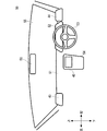
- FIG. 2 is a view of the vehicle 50 as viewed from the inside of the vehicle.
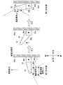
- FIG. 3 is a diagram of the left side surface 50a of the vehicle 50 as viewed from above.
- the vehicular video system 100 includes a vehicular video control device 20, a front camera 31, a rear camera 32, a left camera 33, a right camera 34, a left support portion 35, and a right support.
- the unit 36, the operation unit 37, the GPS receiving unit 38, the recording unit 41, the sensor 42, the left side monitor 43, the right side monitor 44, and the infotainment monitor 45 are provided.
- the video system 100 for a vehicle is mounted on the vehicle 50 shown in FIG.
- the front camera 31, the rear camera 32, the left camera 33, and the right camera 34 may be imaging devices. That is, the front camera 31 is a front imaging device, the rear camera 32 is a rear imaging device, the left camera 33 is a left imaging device, and the right camera 34 is a right imaging device.
- the front camera 31 and the rear camera 32 may be cameras used in a general drive recorder. Further, the left camera 33 and the right camera 34 may be cameras used for general electronic mirrors.
- the front camera 31 is arranged on the front side of the vehicle 50 so as to face the front of the vehicle 50, and photographs the front of the vehicle 50.
- the rear camera 32 is arranged on the rear side of the vehicle 50 so as to face the rear of the vehicle 50 and captures an image of the rear of the vehicle 50.
- the front camera 31 and the rear camera 32 output the captured video data to the captured data acquisition unit 1.
- the left support portion 35 includes a base 35a and an arm 35b.
- the base 35a is provided on the left side surface 50a of the vehicle 50.
- the arm 35b is provided on the base 35a so as to be rotatable around a shaft 35c.
- the shaft 35c extends linearly in the vertical direction of the vehicle 50. Therefore, when the arm 35b rotates around the axis 35c, the arm 35b rotates and moves on the horizontal plane of the vehicle 50.
- the left support part 35 rotationally moves the arm 35b based on the control signal received from the support control part 2.
- the left camera 33 is provided on the rear side of the tip of the arm 35b.
- the left camera 33 faces the direction substantially orthogonal to the longitudinal direction of the arm 35b on the horizontal plane of the vehicle 50.
- the left camera 33 is arranged at the first position or the second position by rotating the arm 35b around the shaft 35c.
- the longitudinal direction of the arm 35b is substantially perpendicular to the left side surface 50a of the vehicle 50, the left camera 33 is in the first position.
- the left camera 33 images the left rear of the vehicle 50.
- the left camera 33 is in the first position, the vehicle 50 is often driven by the driver, and the left camera 33 functions as an electronic mirror.
- the left camera 33 When the front side of the tip of the arm 35b and the left side surface 50a of the vehicle 50 face each other, the left camera 33 is in the second position.
- the left camera 33 images the left side of the vehicle 50.
- the left camera 33 outputs the captured video data to the captured data acquisition unit 1.
- the left camera 33 When the left camera 33 is in the second position, the vehicle 50 is often parked and the left camera 33 functions as a drive recorder.
- the right support portion 36 shown in FIG. 1 has the same configuration as the left support portion 35 and is symmetrical with respect to the center line extending in the front-rear direction of the left support portion 35 and the vehicle 50. Although details of the right support portion 36 are not shown, specifically, the right support portion 36 has a bilaterally symmetrical structure in which the reference numeral 35 in FIG. 3 is replaced with 36.
- the right support portion 36 includes a base 36a and an arm 36b, like the left support portion 35.
- the base 36a is provided on the right side surface of the vehicle 50.
- the arm 36b is provided on the base 36a so as to be rotatable around a shaft 36c.
- the shaft 36c extends linearly in the vertical direction of the vehicle 50. Therefore, when the arm 36b rotates about the shaft 36c, the arm 36b rotates and moves on the horizontal plane of the vehicle 50.
- the right support section 36 rotates the arm 36b based on the control signal received from the support control section 2.
- the right camera 34 is provided behind the tip of the arm 36b of the right support 36.
- the right camera 34 faces the direction substantially orthogonal to the longitudinal direction of the arm 36b on the horizontal plane of the vehicle 50.
- the right camera 34 and the left camera 33 are arranged at the first position or the second position.
- the arm 35b and the arm 36b have the longitudinal direction of the arm 35b and the arm 36b substantially orthogonal to the right side surface of the vehicle 50, the right camera 34 is in the first position.
- the right camera 34 images the right rear of the vehicle 50.
- the right camera 34 When the front side of the tip of the arm 36b and the right side surface of the vehicle 50 face each other, the right camera 34 is in the second position.
- the right camera 34 images the right side of the vehicle 50.
- the right camera 34 outputs the captured video data to the captured data acquisition unit 1.
- the operation unit 37 is an interface, receives an operation input from an operator such as a driver, generates a signal indicating an operation, and outputs the signal to the operation control unit 3.
- the GPS receiving unit 38 receives a signal from a GPS (Global Positioning System) and outputs the received signal to the position information acquisition unit 4.
- GPS Global Positioning System
- the recording unit 41 stores the shooting data acquired by the recording control unit 7 from the shooting data acquisition unit 1.
- the recording unit 41 is, for example, a semiconductor memory device such as an EPROM (Erasable PROM), a flash ROM, a RAM (Random Access Memory), or a storage device such as a hard disk, an optical disk, a memory card, or an external storage device via a network. is there.
- the recording unit 41 may be an external storage device wirelessly connected via a communication device (not shown).
- the recording unit 41 causes the recording control unit 7 and the reproduction control unit 8 to read or add recording.
- the sensor 42 is a sensor that appropriately measures a wide variety of measurement targets, for example, an acceleration sensor that measures acceleration.
- the sensor 42 outputs the measured measurement result to the event detection unit 9.
- the left side monitor 43 is, for example, a display device including a liquid crystal display, an organic EL display, or the like.
- the left side monitor 43 displays the video imaged by the left camera 33 of the vehicle 50 based on the video signal output from the display control unit 10.
- the right side monitor 44 is a display device including, for example, a liquid crystal display, an organic EL display, or the like.
- the right side monitor 44 displays the video imaged by the right camera 34 of the vehicle 50 based on the video signal output from the display control unit 10.
- the infotainment monitor 45 is a display device including, for example, a liquid crystal display, an organic EL display, or the like.
- the infotainment monitor 45 displays a wide variety of images based on the image signal output from the display control unit 10.
- the infotainment monitor 45 may be dedicated to the vehicular image system 100, or may be used in collaboration with another system including a navigation system, for example.
- the vehicular image control device 20 includes a shooting data acquisition unit 1, a support control unit 2, an operation control unit 3, a position information acquisition unit 4, a buffer memory 5, and a shooting data processing unit. 6, a recording control unit 7, a reproduction control unit 8, an event detection unit 9, a display control unit 10, and a mode changing unit 11.
- the vehicle video control device 20 can be configured by a processor such as a CPU (Central Processing Unit). That is, the vehicular image control device 20 can have a function as a computer. The vehicular image control device 20 can execute various processes by executing a program stored in the storage device. Further, the vehicle video control device 20 executes this program to execute the shooting data acquisition unit 1, the support control unit 2, the operation control unit 3, the position information acquisition unit 4, the shooting data processing unit 6, and the recording control unit 7. , A reproduction control unit 8, an event detection unit 9, a display control unit 10, and a mode changing unit 11.
- a processor such as a CPU (Central Processing Unit). That is, the vehicular image control device 20 can have a function as a computer.
- the vehicular image control device 20 can execute various processes by executing a program stored in the storage device. Further, the vehicle video control device 20 executes this program to execute the shooting data acquisition unit 1, the support control unit 2, the operation control unit 3, the position information acquisition unit 4, the shooting data processing unit 6, and the recording control unit 7. , A reproduction control unit 8,
- the storage device may include, for example, a DDR (Double Data Rate) memory, a flash memory (flash memory), or the like as a part of the vehicle video control device 20 or outside the vehicle video control device 20.
- the vehicular video system 100 may include an EEPROM as a part of the vehicular video control device 20 or outside the vehicular video control device 20.
- the storage device may be the recording unit 41.
- each component of the vehicle video system 100 is not limited to being realized by a program, but may be realized by hardware, or a combination of hardware and a program. Further, each component of the vehicular image control device 20 may be realized by a user programmable integrated circuit such as an FPGA (field-programmable gate array) or a microcomputer. In this way, the vehicular video control device 20 may realize the functions of the respective constituent elements of the vehicular video control device 20 by using this integrated circuit.
- FPGA field-programmable gate array
- Each component constituting the vehicle image control device 20, such as the display control unit 10 and the mode changing unit 11, is software or a module that is executed by the processor executing a program stored in the memory. May be.
- each constituent element of the vehicular image control device 20 may be hardware such as a circuit or a chip.
- the shooting data acquisition unit 1 acquires the video data generated by the front camera 31, the rear camera 32, the left camera 33, and the right camera 34.
- Data including video data may be referred to as shooting data.
- the captured data acquisition unit 1 may acquire captured data from the front camera 31, the rear camera 32, the left camera 33, and the right camera 34.
- the shooting data may include audio data in addition to video data.
- the operation control unit 3 generates operation input information based on the signal from the operation unit 37 and outputs it to the support control unit 2.
- the operation input information generated by the operation control unit 3 indicates, for example, an operation for switching the left support portion 35 and the right support portion 36 so as to be located at either the first position or the second position.
- the support control unit 2 acquires the operation input information from the operation control unit 3.
- the support control unit 2 also acquires power ON/OFF information indicating whether the power of the vehicle 50 is ON or OFF.
- the support control unit 2 may acquire the power ON/OFF information of the vehicle 50 via a CAN (Controller Area Network), for example.
- the support control unit 2 acquires various detection information from various sensors 42 such as an acceleration sensor, calculates the acquired detection information, and derives power ON/OFF information of the vehicle 50. Good.
- the operation input information and the power ON/OFF information indicate that the power of the vehicle 50 is ON, the vehicle 50 is in a state of being driven by the driver.
- the operation input information and the power ON/OFF information indicate that the power of the vehicle 50 is OFF, the vehicle 50 is in a parked state.
- the support control unit 2 sends a control signal corresponding to the operation input information or the power ON/OFF information from the operation control unit 3 to the left support unit 35 and the right support unit 36.
- the support control unit 2 controls the left support unit 35 and the right support unit 36 at the first position.
- the support control unit 2 controls the left support unit 35 and the right support unit 36 at the second position. To send.
- the position information acquisition unit 4 acquires the signal received by the GPS reception unit 38 and generates the current position information of the vehicle 50.
- the buffer memory 5 temporarily stores the output shooting data, for example.
- the shooting data processing unit 6 sends the shooting data temporarily stored in the buffer memory 5 to, for example, H.264.
- Shooting data as a data file for a certain period is generated using an arbitrary method such as H.264 or MPEG-4 (Moving Picture Experts Group).
- the recording control unit 7 records the shooting data generated by the shooting data processing unit 6 in the recording unit 41 as overwritable data or overwriting prohibited data.
- the recording control unit 7 may record the photographing data in the recording unit 41 by designating the address of the memory area in which the data of the recording unit 41 can be overwritten or prohibited.
- the recording control unit 7 may set flag information indicating overwriting prohibition or overwriting prohibition in the header or the payload of the photographing data.
- the event detection unit 9 outputs information indicating that an event has occurred to the recording control unit 7, the recording control unit 7 determines that the shooting data in a predetermined period before and after the time when the event has occurred is the overwriting prohibition data. The data is recorded in the recording unit 41.
- the reproduction control unit 8 acquires the shooting data recorded in the recording unit 41 and outputs the video data based on the acquired shooting data to the display control unit 10.
- the event detection unit 9 detects the event occurrence using the information output from the sensor 42. For example, when the acceleration detected by the sensor 42 that operates as an acceleration sensor exceeds a predetermined value, the event detection unit 9 detects that an event has occurred. The acceleration exceeding the predetermined value may be rephrased as a shock applied to the vehicle 50 corresponding to an accident. In addition to the event detection based on acceleration, the event detection unit 9 detects a moving body from the video data acquired by the imaging data acquisition unit while the vehicle 50 is parked, and detects that the moving body is detected. It may occur. When detecting the occurrence of the event, the event detection unit 9 outputs information indicating that the event has occurred to the recording control unit 7. The information indicating that the event has occurred includes the time when the event occurred. Further, the information indicating that the event has occurred may include the content of the event that has occurred.
- the display control unit 10 displays a video based on the video data acquired from the reproduction control unit 8, the buffer memory 5 and the like on the left side monitor 43, the right side monitor 44, the infotainment monitor 45 and the like.
- the display control unit 10 cuts out a predetermined area from the video data captured by the left camera 33 and the right camera 34, and generates video data to be displayed on the left side monitor 43 and the right side monitor 44. For example, when the angle of view captured by the left camera 33 and the right camera 34 is 150 degrees to 180 degrees in the horizontal direction and 90 degrees to 120 degrees in the vertical direction, the display control unit 10 causes the left camera 33 and the right camera 34 to operate. From the photographed video data, a range of 60 degrees to 90 degrees in the horizontal direction and 45 degrees to 60 degrees in the vertical direction are cut out and displayed on the left side monitor 43 and the right side monitor 44, respectively.
- the mode change unit 11 causes the display control unit 10 to display the video data captured by the left camera 33 and the right camera 34. , The left side monitor 43 and the right side monitor 44.
- the mode changing unit 11 causes the recording control unit 7 to display images captured by the left camera 33 and the right camera 34.
- the data is used as monitoring information for monitoring the vehicle 50.
- the mode changing portion 11 uses the left side monitor 43 and the right side monitor 44, which are electronic mirrors, to control the left and right sides of the vehicle 50.
- the mode changing unit 11 switches between the electronic mirror mode and the drive recorder mode.
- FIG. 2 is a schematic diagram showing a configuration example in front of a driver's seat of a vehicle in which the vehicle video system 100 according to the first embodiment is mounted.
- an image is displayed on the horizontally elongated infotainment monitor 45 arranged on the center console 54.
- infotainment monitor 45 and the center console 54 a left side monitor 43, a right side monitor 44, a dashboard 51, an instrument panel 52, a steering wheel are provided in front of the driver's seat in the vehicle shown in FIG. 53, a windshield 55, a rear view monitor 56 and the like are arranged.
- the left side monitor 43, the right side monitor 44, and the infotainment monitor 45 are arranged at positions where the driver can visually recognize them.
- the left side monitor 43 is arranged on the left side of the dashboard 51 of the vehicle 50 in the left-right direction.
- the right side monitor 44 is arranged on the right side of the dashboard 51 of the vehicle 50 in the left-right direction.
- the infotainment monitor 45 is arranged on the center console 54 located near the center of the dashboard 51 in the left-right direction.
- the instrument panel 52 is arranged on the dashboard 51 below the windshield 55, and displays a speedometer, an engine tachometer, and the like.
- the steering wheel 53 is for the driver to perform steering operation.
- the steering direction of the vehicle is changed according to the steering operation by the steering wheel 53.
- the rear view monitor 56 is a monitor for the driver to confirm the rear of the vehicle, and is, for example, an electronic room mirror or a display device including a liquid crystal display, an organic EL display, or the like.
- the rear view monitor 56 may display a video image of the rear of the vehicle 50 based on a video signal from the display control unit 10.
- the rear view monitor 56 is arranged at a position visible to the driver.
- the rear view monitor 56 according to the present embodiment is arranged above the center of the windshield 55 in the left-right direction.
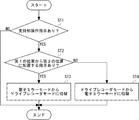
- the mode changing unit 11 determines whether the operation control unit 3 has received an instruction to operate the left support unit 35 and the right support unit 36 (support unit operation instruction determination step ST1).
- support portion operation instruction determination step ST1 When an instruction to operate the left support portion 35 and the right support portion 36 is received (support portion operation instruction determination step ST1: YES), the received instruction causes the left support portion 35 and the right support portion 36 to move to the first position. It is determined whether or not it is an instruction indicating to place it in the second position (second position placement instruction determination step ST2).
- step ST1 If the instruction received in step ST1 indicates that the left support portion 35 and the right support portion 36 are to be arranged from the first position to the second position (second position arrangement instruction determination step ST2: YES), electronic The mirror mode is switched to the drive recorder mode (drive recorder mode switching step ST3).
- the support control unit 2 When switching to the drive recorder mode, the support control unit 2 sends a control signal to the left support unit 35 and the right support unit 36, and causes the left support unit 35 and the right support unit 36 to move from the first position to the left side surface of the vehicle of the vehicle 50. By rotating it to the side of 50a, it is moved so as to be close to it and is arranged at the second position.
- the left support portion 35 and the right support portion 36 are arranged in the second position, the images captured by the left camera 33, the right camera 34, the front camera 31, and the rear camera 32 are recorded by the recording unit 41 as a function of the drive recorder. Recorded in.
- the recording control unit 7 records the video imaged by the left camera 33 and the right camera 34 in the recording unit 41 as video data of the view angle ⁇ 1.
- the angle of view ⁇ 1 may be any width as long as the images captured by the left camera 33 and the right camera 34 are suitable for the recording image of the drive recorder, and may be the maximum angle of view of the left camera 33 and the right camera 34. ..
- the angle of view ⁇ 1 is, for example, 150 degrees to 180 degrees in the horizontal direction and 90 degrees to 120 degrees in the vertical direction.
- the video recorded in the recording unit 41 can be used as monitoring information.
- the drive recorder mode is switched to the electronic mirror mode (electronic mirror mode switching step ST4). ..
- the left support portion 35 and the right support portion 36 are arranged at the first position.
- the image captured by the left camera 33 is displayed on the left side monitor 43
- the image captured by the right camera 34 is displayed on the right side monitor 44.
- the captured data acquisition unit 1 acquires the images captured by the left camera 33 and the right camera 34, and the display control unit 10 displays them on the left side monitor 43 and the right side monitor 44.
- the display control unit 10 causes the left side monitor 43 and the right side monitor 44 to display an image obtained by cutting out a part of the angle of view ⁇ 1 of the image captured by the left camera 33 and the right camera 34.
- the angle of view ⁇ 2 of the display image displayed on the left side monitor 43 and the right side monitor 44 is, for example, 60 degrees or more and 90 degrees or less in the horizontal direction.
- the angle of view ⁇ 2 is preferably narrower than the angle of view ⁇ 1.
- the angle of view ⁇ 2 may have a suitable width when the display image is used for the electronic mirror.
- the angle of view ⁇ 2 is, for example, 60° to 90° in the horizontal direction and 45° to 60° in the vertical direction.
- the images captured by the front camera 31 and the rear camera 32 are recorded in the recording portion 41 as a function of the drive recorder.
- shooting data based on the images shot by the front camera 31 and the rear camera 32 is temporarily stored in the buffer memory 5, processed by the shooting data processing unit 6, and a predetermined file is generated.
- the shooting data processing unit 6 sends the acquired shooting data to, for example, H.264. It is encoded and processed by a codec of any system such as H.264 or MPEG-4.
- the predetermined file is, for example, an arbitrary file format such as MP4 format, and the time of the captured image indicated by the predetermined file is, for example, 60 seconds or the like.
- the recording control unit 7 records the file generated by the photographing data processing unit 6 in the recording unit 41 so that the file can be overwritten.
- the recording control unit 7 saves the images of a predetermined period before and after the event detection in the recording unit 41 as overwriting prohibited data.
- the images captured by the left camera 33 and the right camera 34 are used as an electronic mirror and the front camera 31 and The image captured by the rear camera 32 is used as the image of the drive recorder. Further, when the left support portion 35 and the right support portion 36 are arranged at the second position, the front camera 31 and the rear camera 32 capture images in addition to the images captured by the left camera 33 and the right camera 34. The video being played is also used as the video of the drive recorder.
- the front-back direction of the vehicle 50 can be imaged and the imaged video can be recorded while the vehicle 50 is in use or is running.
- the vehicular image system 100 uses a front camera 31, a rear camera 32, etc. used for a general drive recorder, and a left camera 33, a right camera 34, etc. used for a general electronic mirror, The effects described above can be exhibited. That is, the video system 100 for a vehicle can exert the above-mentioned effects by using a hardware configuration used for a general drive recorder and an electronic mirror, without using any other hardware configuration, resulting in an increase in cost. Can be suppressed.
- FIG. 5 is a block diagram showing a configuration example of a vehicle video system according to the second embodiment.
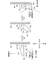
- FIG. 6 is a schematic diagram showing an operation example of the vehicular image system according to the second embodiment, and is a view of the left side surface 50a of the vehicle 50 as viewed from above.
- the vehicular video system 200 according to the second embodiment has the same configuration as the vehicular video system 100 shown in FIG. 1 except for the left support section, the right support section, the left camera, and the right camera.
- the vehicle video system 200 includes a left first camera 33a, a left second camera 33b, a right first camera 34a, a right second camera 34b, and a left support portion 235. And a right support portion 236.
- the left first camera 33a, the left second camera 33b, the right first camera 34a, and the right second camera 34b may be imaging devices. That is, the left first camera 33a and the left second camera 33b configure a left imaging device, and the right first camera 34a and the right second camera 34b configure a right imaging device.
- the left first camera 33a, the left second camera 33b, the right first camera 34a, and the right second camera 34b may be cameras used for general electronic mirrors.
- the left support portion 235 has the same configuration as the left support portion 35 shown in FIGS. 1 and 3, except for the operation of the arm 35b.
- the left first camera 33a is provided on the rear side of the tip of the arm 35b.
- the left second camera 33b is provided on the front side of the tip of the arm 35b.
- the left first camera 33a is oriented in a direction substantially orthogonal to the longitudinal direction of the arm 35b on the horizontal plane of the vehicle 50, and the left second camera 33b is different from the direction in which the left first camera 33a is oriented. Facing in the opposite direction.
- the left first camera 33a and the left second camera 33b are arranged at the first position or the second position.
- the left first camera 33a and the left second camera 33b are present at the first position.
- the left first camera 33a images the left rear of the vehicle 50.
- the first left camera 33a outputs the captured video data to the captured data acquisition unit 1.
- the left first camera 33a and the left second camera 33b are present at the second position.
- the second left camera 33b images the left side of the vehicle 50.
- the left second camera 33b outputs the captured video data to the captured data acquisition unit 1.
- the second left camera 33b and the second right camera 34b are preferably capable of shooting images with a larger angle of view than the left first camera 33a and the right first camera 34a.
- the second left camera 33b and the second right camera 34b are cameras that capture an angle of view ⁇ 4 of, for example, 150 degrees to 180 degrees in the horizontal direction and 90 degrees to 120 degrees in the vertical direction.
- the first left camera 33a and the first right camera 34a are cameras that capture an angle of view ⁇ 3 such as 60 to 90 degrees in the horizontal direction and 45 to 60 degrees in the vertical direction.
- the angle of view ⁇ 3 is preferably narrower than the angle of view ⁇ 4.
- the angle of view ⁇ 3 may have a suitable width when the images captured by the first left camera 33a and the first right camera 34a are used for the electronic mirror.
- the angle of view ⁇ 4 is preferably a size suitable for the images recorded by the drive recorder, as the images captured by the left second camera 33b and the right second camera 34b.
- the right support portion 236 shown in FIG. 5 has the same configuration as the left support portion 235, and is provided so as to be bilaterally symmetrical with respect to a center line extending in the front-rear direction of the vehicle 50.
- the right first camera 34a has the same configuration as the left first camera 33a, and is provided so as to be bilaterally symmetrical with respect to a center line extending in the front-rear direction of the vehicle 50.
- the right second camera 34b has the same configuration as the left second camera 33b, and is provided so as to be bilaterally symmetrical with respect to the center line extending in the front-rear direction of the vehicle 50.
- FIGS. 4 and 6 An operation example of the operation of the vehicular video system 200 will be described with reference to FIGS. 4 and 6.
- An operation example of the operation of the vehicle image system 200 has the same configuration as the operation example of the vehicle image system 100 described above, except for the drive recorder mode switching step ST3 and the electronic mirror mode switching step ST4.
- the support portion operation instruction determination step ST1 and the second position placement instruction determination step ST2 shown in FIG. 4 are performed, and the process proceeds to the drive recorder mode switching step ST3 or the electronic mirror mode switching step ST4.
- the support control unit 2 sends a control signal to the left support unit 235 and the right support unit 236, and the left first camera 33a and the left second camera 33b.
- the right first camera 34a, and the right second camera 34b are arranged at the second position.
- Images captured by the second left camera 33b, the second right camera 34b, the front camera 31, and the rear camera 32 are recorded in the recording unit 41 as a function of the drive recorder.
- the display control unit 10 records in the recording unit 41 the images captured by the left second camera 33b and the right second camera 34b.
- the support control unit 2 sends a control signal to the left support unit 235 and the right support unit 236.
- the left support portion 235 and the right support portion 236 arrange the left first camera 33a, the left second camera 33b, the right first camera 34a, and the right second camera 34b at the first position.
- the left first camera 33a When the left first camera 33a, the left second camera 33b, the right first camera 34a, and the right second camera 34b are arranged at the first position, the left first camera 33a is shooting.
- the image is displayed on the left side monitor 43.
- the image captured by the first right camera 34a is also displayed on the right side monitor 44.
- the images captured by the left first camera 33a and the right first camera 34a have an angle of view ⁇ 3 and are suitable for use as an electronic mirror. Therefore, the display control unit 10 of the vehicular video system 200 does not need to generate a display video data by cutting out a predetermined range from the video captured by the left first camera 33a and the right first camera 34a. ..
- the display control unit 10 of the vehicular video system 200 may have a simple configuration, unlike the vehicular video system 200 shown in FIG. 1.
- the left second camera 33b and the right second camera 34b When operating in the electronic mirror mode, the left second camera 33b and the right second camera 34b may not be photographing. Further, when operating in the electronic mirror mode, the left second camera 33b and the right second camera 34b may be operated, and a process of recognizing a person or another vehicle may be performed on this image.
- the vehicular video system 200 monitors an obstacle in front of the vehicle 50 based on the information obtained by this processing, and appropriately prompts the driver to the left side monitor 43, the right side monitor 44, or the infotainment monitor 45. May be used for notification.
- the images captured by the left second camera 33b and the right second camera 34b may be appropriately recorded in the recording unit 41.
- the images captured by the front camera 31, the second left camera 33b, and the second right camera 34b have a wider angle of view than the images captured by only the front camera 31. Therefore, a large area in front of the vehicle 50 can be monitored using the images captured by the front camera 31, the second left camera 33b, and the second right camera 34b.
- the front-back direction of the vehicle 50 can be captured while the vehicle 50 is in use or running, and the captured video can be recorded. it can.
- the vehicular image system 200 includes a front camera 31, a rear camera 32, and the like used in a general drive recorder, and a left first camera 33a and a left second camera 33b used in a general electronic mirror.
- the video system 200 for a vehicle can exert the above-mentioned effects by using a hardware configuration used for a general drive recorder and an electronic mirror without using any other hardware configuration, resulting in an increase in cost. Can be suppressed.
- FIG. 7 is a schematic diagram showing an operation example of a modified example of the main part of the vehicle video system according to the second embodiment, and is a view of the left side surface 50a of the vehicle 50 as viewed from above.
- the vehicular video system 201 has the same configuration as the vehicular video system 200 shown in FIG. 5, except for the left camera 33c and a right camera (not shown).
- the left camera 33c may be an imaging device.
- the left camera 33c may be a camera used for a general electronic mirror or a drive recorder.
- the left camera 33c is provided at the tip of the arm 35b so as to be rotatable around the shaft 33d.
- the shaft 33d extends in the vertical direction.
- the left camera 33c may include, for example, a power source such as a motor, and is rotated by the power source so as to face a predetermined direction around the shaft 33d.
- the left camera 33c is arranged at the first position or the second position by rotating the arm 35b shown in FIG. 7 around the shaft 35c.
- the left camera 33c rotates about the axis 35c and faces another direction with respect to the arm 35b.
- the left camera 33c is present at the first position.
- the left camera 33c images the left rear of the vehicle 50.
- the left camera 33c outputs the captured video data to the captured data acquisition unit 1.
- the left camera 33c When the rear side of the tip of the arm 35b and the left side surface 50a of the vehicle 50 face each other, the left camera 33c is present at the second position. In this case, the left camera 33c images the left side of the vehicle 50. The left camera 33 outputs the captured video data to the captured data acquisition unit 1.
- the right camera (not shown) has the same configuration as the left camera 33c, and is provided so as to be bilaterally symmetrical with respect to the center line extending in the front-rear direction of the vehicle 50.
- An operation example of the operation of the vehicle image system 201 has the same configuration as that of the operation example of the vehicle image system 200 described above, except for the drive recorder mode switching step ST3 and the electronic mirror mode switching step ST4.
- the support portion operation instruction determination step ST1 and the second position placement instruction determination step ST2 shown in FIG. 4 are performed, and the process proceeds to the drive recorder mode switching step ST3 or the electronic mirror mode switching step ST4.
- the support control unit 2 sends a control signal to the left support unit 235 and the right support unit 236, and the left camera 33c and the right camera (not shown) are switched to the second camera. Place in position. Further, the left camera 33c appropriately rotates around the shaft 33d and faces the rear side of the tip of the arm 35b. The right camera (not shown) also rotates in the same manner as the left camera 33c to change the direction.
- the images captured by the left camera 33c, the right camera (not shown), the front camera 31, and the rear camera 32 are recorded in the recording unit 41 as a function of the drive recorder.
- the display control unit 10 records the video imaged by the left camera 33c and the right camera (not shown) in the recording unit 41.
- the video imaged by the left camera 33c and the right camera (not shown) has an angle of view ⁇ 1.
- the angle of view ⁇ 1 may have a width suitable for the images captured by the left camera 33c and the right camera (not shown) as the images recorded by the drive recorder.
- the support control unit 2 sends a control signal to the left support unit 235 and the right support unit 236.
- the left support part 235 and the right support part 236 arrange
- the right camera (not shown) also rotates in the same manner as the left camera 33c to change the direction.
- the display control unit 10 causes the left side monitor 43 and the right side monitor 44 to display an image obtained by cutting out a predetermined range from the angle of view ⁇ 1 of the image captured by the left camera 33c and the right camera (not shown).
- the angle of view ⁇ 2 of the display image displayed on the left side monitor 43 and the right side monitor 44 is, for example, 60 degrees or more and 90 degrees or less in the horizontal direction.
- the angle of view ⁇ 2 is preferably narrower than the angle of view ⁇ 1.
- the angle of view ⁇ 2 may have a suitable width when the display image is used for the electronic mirror.
- the vehicular video system 201 similarly to the vehicular video system 200, while the vehicle 50 is in use or running, the front-back direction of the vehicle 50 can be captured and the captured video can be recorded. it can.
- the vehicular image system 201 uses the front camera 31, the rear camera 32, and the like used in a general drive recorder, and the camera, etc., used in a general electronic mirror or drive recorder, to achieve the above-mentioned effects.
- the vehicular image system 201 can exert the above-mentioned effects by using a hardware configuration used for a general drive recorder and an electronic mirror without using any other hardware configuration, resulting in an increase in cost. Can be suppressed.
- the left camera and the right camera are fewer than the vehicular video system 200.
- the vehicular video system 201 has a simpler configuration of the left camera and the right camera than the vehicular video system 200.
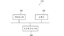
- FIG. 8 is a diagram showing an example of a hardware configuration included in the vehicle video system 100, 200, 201.
- the vehicle video system 110 shown in FIG. 8 includes an interface 103 such as an interface for the operation unit 37, a processor 101, and a memory 102.
- the vehicular image control device 20 described in the above-described embodiment is realized by the processor 101 reading and executing the control program stored in the memory 102. That is, this control program is a program for causing the processor 101 to function as the vehicular image control device 20 of FIG. 1 or a part thereof. It can be said that this control program is a program for causing the vehicular video system 100 of FIG. 1 to execute processing in the vehicular video control device 20 or a part thereof.
- Non-transitory computer-readable media include various types of tangible storage media. Examples of non-transitory computer readable media include magnetic recording media (eg, flexible disks, magnetic tapes, hard disk drives), magneto-optical recording media (eg, magneto-optical disks). Furthermore, this example includes a CD-ROM (Read Only Memory), a CD-R, and a CD-R/W. Further, this example includes semiconductor memory (eg, mask ROM, PROM, EPROM, flash ROM, RAM). In addition, the program may be supplied to the computer by various types of transitory computer readable media. Examples of transitory computer-readable media include electrical signals, optical signals, and electromagnetic waves. The transitory computer-readable medium can supply the program to the computer via a wired communication path such as an electric wire and an optical fiber, or a wireless communication path.
- a wired communication path such as an electric wire and an optical fiber, or a wireless communication path.
- the present invention can also take a form as a video control method.
- This video control method includes the following first and second steps.
- the first step is a left supporting portion provided on the left side of the vehicle for supporting a left imaging device for photographing the left side of the vehicle and a right supporting part provided on the right side of the vehicle for supporting a right imaging device for photographing the right side of the vehicle.
- a second step when the left support portion and the right support portion are arranged in the first position by the support control step, the images captured by the left image pickup device and the right image pickup device are recorded in the vehicle.
- the left support portion and the right support portion are arranged at the second position by displaying the images on the monitor visible to the driver, the images captured by the left imaging device and the right imaging device are displayed on the vehicle.
- This is a mode changing step to be used as monitoring information to be monitored.
- control program is a video control program for causing the vehicular video system to execute such a video control method.
- the present invention is not limited to the above-described embodiment, and can be modified as appropriate without departing from the spirit of the present invention. Further, the present invention may be implemented by appropriately combining the embodiments and the examples thereof.
- the present invention can be applied to, for example, a vehicle image control device for a vehicle equipped with a camera, a vehicle image system, an image control method, and a program.
Abstract
A video control device (20) for vehicles comprises: a support control unit (2) for controlling left and right supports (35, 36) for supporting imaging devices (33, 34) provided on the left and right sides of a vehicle (50) so as to be placeable at a first position where the imaging devices (33, 34) face the left and right rearward of the vehicle (50) and a second position where the imaging devices (33, 34) face the left and right direction of the vehicle (50); a display control unit (10) for causing the videos imaged by the imaging devices (33, 34) to be displayed on a monitor visible to the driver of the vehicle (50); a recording control unit (7) for utilizing the videos imaged by the imaging devices (33, 34) as monitoring information for monitoring the vehicle (50); and a mode change unit (11) for causing the videos imaged by the imaging devices (33, 34) to be displayed on monitors (43, 44) when the left and right supports (35, 36) are placed at the first position and causing the same to be utilized as monitoring information when the placed at the second position.
Description
本発明は、車両用映像制御装置、車両用映像システム、映像制御方法、及びプログラムに関し、特にカメラを搭載した車両の車両用映像制御装置、車両用映像システム、映像制御方法、及びプログラムに関する。
The present invention relates to a vehicle image control device, a vehicle image system, an image control method, and a program, and particularly to a vehicle image control device for a vehicle equipped with a camera, a vehicle image system, an image control method, and a program.
一般的にドライブレコーダは、車両の進行方向である前後方向を重点的に撮影するように構成されている。
Generally, the drive recorder is configured to focus on the front-back direction, which is the traveling direction of the vehicle.
駐車監視モードにおいては、車両の横方向で発生したイベントの原因等も記録できるように、特許文献1においては、半天球カメラを備えたドライブレコーダが開示されている。また、近年において、車両のサイドミラーに代えて車両の側後方を撮影するカメラの映像を表示する電子ミラーが備えられている。
In Patent Document 1, a drive recorder equipped with a hemisphere camera is disclosed so that the cause of an event occurring in the lateral direction of the vehicle can be recorded in the parking monitoring mode. In recent years, instead of the side mirror of the vehicle, an electronic mirror that displays a video image of a camera that photographs the side rear of the vehicle is provided.
ドライブレコーダは、車両の走行中を含む車両の使用中、車両の前後方向を撮像し、その撮像した映像を記録することが期待される。一方、ドライブレコーダは、駐車中に、前後方向に限らず、車両の前後方向に加えて左右方向を監視することが要求されているが、特許文献1に開示の半天球カメラは、車室外の映像を適切に記録することが困難である。さらに、左右方向を監視するためのカメラを車両に取り付けると、コストが増大するおそれがあった。
The drive recorder is expected to capture an image of the front-back direction of the vehicle and record the captured image while the vehicle is in use, including when the vehicle is running. On the other hand, the drive recorder is required to monitor not only the front-rear direction but also the left-right direction in addition to the front-rear direction of the vehicle during parking. It is difficult to record video properly. Furthermore, if a camera for monitoring the left-right direction is attached to the vehicle, the cost may increase.
本発明は、コスト増大を抑制して適切な駐車監視を行うことができる、車両用映像制御装置、車両用映像システム、映像制御方法、及びプログラムを提供する。
The present invention provides a vehicle image control device, a vehicle image system, an image control method, and a program capable of suppressing cost increase and performing appropriate parking monitoring.
本実施形態に係る車両用映像制御装置は、
車両の左側に備えられ前記車両の左側を撮影する左撮像装置を支持する左支持部および前記車両の右側に備えられ前記車両の右側を撮影する右撮像装置を支持する右支持部を、前記左撮像装置が前記車両の左側後方を向き、前記右撮像装置が前記車両の右側後方を向く第1の位置と、前記左撮像装置が前記車両の左方向を向き、前記右撮像装置が前記車両の右方向を向く第2の位置に配置可能に制御する支持制御部と、
前記左撮像装置および前記右撮像装置が撮影した映像を、前記車両の運転者が視認可能なモニタに表示させる表示制御部と、
前記左撮像装置および前記右撮像装置が撮影した映像を、前記車両を監視する監視情報として利用する記録制御部と、
前記支持制御部によって前記左支持部および前記右支持部が前記第1の位置に配置された場合、前記表示制御部に前記左撮像装置および前記右撮像装置が撮影した映像を、前記車両の運転者が視認可能なモニタに表示させ、前記左支持部および前記右支持部が前記第2の位置に配置された場合、前記記録制御部に前記左撮像装置および前記右撮像装置が撮影した映像を、前記車両を監視する監視情報として利用させるモード変更部と、
を備える。 The video control device for a vehicle according to the present embodiment,
A left support part that is provided on the left side of the vehicle and supports a left imaging device that captures the left side of the vehicle; and a right support part that is provided on the right side of the vehicle that supports the right imaging device that captures the right side of the vehicle, A first position in which the imaging device faces the left rear of the vehicle, the right imaging device faces the right rear of the vehicle, the left imaging device faces the left direction of the vehicle, and the right imaging device of the vehicle A support control unit that controls the second position facing the right direction so that the support control unit can be arranged;
A display control unit that causes the image captured by the left imaging device and the right imaging device to be displayed on a monitor visible to the driver of the vehicle,
A recording controller that uses the images captured by the left imaging device and the right imaging device as monitoring information for monitoring the vehicle;
When the left support section and the right support section are arranged at the first position by the support control section, the image captured by the left image pickup apparatus and the right image pickup apparatus is displayed on the display control section as the driving of the vehicle. When the left support section and the right support section are arranged at the second position, the images are captured by the left imaging device and the right imaging device in the recording control section. A mode changing unit used as monitoring information for monitoring the vehicle,
Equipped with.
また、本実施形態に係る車両用映像システムは、
上記の前記車両用映像制御装置と、
前記左撮像装置および前記右撮像装置と、を備える車両用映像システムであって、
前記左撮像装置および前記右撮像装置は、それぞれ第1のカメラと、第2のカメラとを備え、
前記左支持部および前記右支持部が前記第1の位置に配置された場合、前記第1のカメラは、前記車両の左側後方および右側後方を向き、
前記左支持部および前記右支持部が前記第2の位置に配置された場合、前記第2のカメラは、前記車両の左方向および右方向を向き、
前記第2のカメラが撮影する撮影映像の画角は、前記第1のカメラが撮影する撮影映像の画角より広い。 Further, the vehicle video system according to the present embodiment,
The above-mentioned vehicle image control device,
A vehicle video system comprising the left imaging device and the right imaging device,
The left imaging device and the right imaging device each include a first camera and a second camera,
When the left support part and the right support part are arranged in the first position, the first camera faces left rear and right rear of the vehicle,
When the left support portion and the right support portion are arranged at the second position, the second camera faces the left direction and the right direction of the vehicle,
The angle of view of the captured image captured by the second camera is wider than the angle of view of the captured image captured by the first camera.
また、本実施形態に係る映像制御方法は、
車両の左側に備えられ前記車両の左側を撮影する左撮像装置を支持する左支持部および前記車両の右側に備えられ前記車両の右側を撮影する右撮像装置を支持する右支持部を、前記左撮像装置が前記車両の左側後方を向き、前記右撮像装置が前記車両の右側後方を向く第1の位置と、前記左撮像装置が前記車両の左方向を向き、前記右撮像装置が前記車両の右方向を向く第2の位置に配置可能に制御する支持制御ステップと、
前記支持制御ステップによって前記左支持部および前記右支持部が前記第1の位置に配置された場合、前記左撮像装置および前記右撮像装置が撮影した映像を、前記車両の運転者が視認可能なモニタに表示させ、前記左支持部および前記右支持部が前記第2の位置に配置された場合、前記左撮像装置および前記右撮像装置が撮影した映像を、前記車両を監視する監視情報として利用させるモード変更ステップと、
を備える。 Further, the image control method according to the present embodiment is
A left support part that is provided on the left side of the vehicle and supports a left imaging device that captures the left side of the vehicle; and a right support part that is provided on the right side of the vehicle that supports the right imaging device that captures the right side of the vehicle, A first position in which the imaging device faces the left rear of the vehicle, the right imaging device faces the right rear of the vehicle, the left imaging device faces the left direction of the vehicle, and the right imaging device of the vehicle A support control step for controlling the second position facing the right direction so that the support control step is possible.
When the left support part and the right support part are arranged at the first position by the support control step, the driver of the vehicle can visually recognize the images captured by the left imaging device and the right imaging device. When displayed on a monitor and the left support portion and the right support portion are arranged at the second position, the images captured by the left imaging device and the right imaging device are used as monitoring information for monitoring the vehicle. Mode change step to
Equipped with.
また、本実施形態に係る映像制御プログラムは、
車両用映像制御装置として動作するコンピュータに、
車両の左側に備えられ前記車両の左側を撮影する左撮像装置を支持する左支持部および前記車両の右側に備えられ前記車両の右側を撮影する右撮像装置を支持する右支持部を、前記左撮像装置が前記車両の左側後方を向き、前記右撮像装置が前記車両の右側後方を向く第1の位置と、前記左撮像装置が前記車両の左方向を向き、前記右撮像装置が前記車両の右方向を向く第2の位置に配置可能に制御する支持制御ステップと、
前記支持制御ステップによって前記左支持部および前記右支持部が前記第1の位置に配置された場合、前記左撮像装置および前記右撮像装置が撮影した映像を、前記車両の運転者が視認可能なモニタに表示させ、前記左支持部および前記右支持部が前記第2の位置に配置された場合、前記左撮像装置および前記右撮像装置が撮影した映像を、前記車両を監視する監視情報として利用させるモード変更ステップと、
実行させる。 Further, the video control program according to the present embodiment,
A computer that operates as a video control device for vehicles,
A left support part that is provided on the left side of the vehicle and supports a left imaging device that captures the left side of the vehicle; and a right support part that is provided on the right side of the vehicle that supports the right imaging device that captures the right side of the vehicle, A first position in which the imaging device faces the left rear of the vehicle, the right imaging device faces the right rear of the vehicle, the left imaging device faces the left direction of the vehicle, and the right imaging device of the vehicle A support control step for controlling the second position facing the right direction so that the support control step is possible.
When the left support part and the right support part are arranged at the first position by the support control step, the driver of the vehicle can visually recognize the images captured by the left imaging device and the right imaging device. When displayed on a monitor and the left support portion and the right support portion are arranged at the second position, the images captured by the left imaging device and the right imaging device are used as monitoring information for monitoring the vehicle. Mode change step to
Let it run.
本実施形態によれば、コスト増大を抑制して適切な駐車監視を行うことができる、車両用映像制御装置、車両用映像システム、映像制御方法、及びプログラムを提供することができる。
According to the present embodiment, it is possible to provide a vehicle image control device, a vehicle image system, an image control method, and a program that can suppress an increase in cost and perform appropriate parking monitoring.
(実施の形態1)
以下、図1~図4を参照して実施の形態1について説明する。図1は、実施の形態1に係る車両用映像システムの一構成例を示すブロック図である。図2は、実施の形態1に係る車両用映像システムが搭載された車両の運転席前方の一構成例を示す模式図である。図3は、実施の形態1に係る車両用映像システムの一動作例を示す模式図である。図4は、実施の形態1に係る車両用映像システムの一動作例を示すフローチャートである。 (Embodiment 1)
Hereinafter, the first embodiment will be described with reference to FIGS. 1 to 4. FIG. 1 is a block diagram showing a configuration example of a vehicle video system according to the first embodiment. FIG. 2 is a schematic diagram showing a configuration example in front of a driver's seat of a vehicle equipped with the vehicle image system according to the first embodiment. FIG. 3 is a schematic diagram showing an operation example of the vehicle video system according to the first embodiment. FIG. 4 is a flowchart showing an operation example of the vehicular video system according to the first embodiment.
なお、当然のことながら、図2及びその他の図面に示した三次元直交座標は、上下方向、左右方向、及び前後方向を示し、構成要素の位置関係を説明するための便宜的なものである。通常、上が鉛直上向き、前後左右方向に延びる平面が水平面であり、図面間で共通である。図2は、車両50の車室内からその前方を視た図である。図3は、車両50の左側面50aをその上側から視た図である。
Naturally, the three-dimensional Cartesian coordinates shown in FIG. 2 and other drawings indicate the up-down direction, the left-right direction, and the front-back direction, and are convenient for explaining the positional relationship of the components. .. Usually, the top is vertically upward, and the plane extending in the front, rear, left, and right directions is a horizontal plane, which is common between the drawings. FIG. 2 is a view of the vehicle 50 as viewed from the inside of the vehicle. FIG. 3 is a diagram of the left side surface 50a of the vehicle 50 as viewed from above.
図1に示すように、車両用映像システム100は、車両用映像制御装置20と、前カメラ31と、後カメラ32と、左カメラ33と、右カメラ34と、左支持部35と、右支持部36と、操作部37と、GPS受信部38と、記録部41と、センサ42と、左サイドモニタ43と、右サイドモニタ44と、インフォティンメントモニタ45とを備える。車両用映像システム100は、図2に示す車両50に搭載されている。
As shown in FIG. 1, the vehicular video system 100 includes a vehicular video control device 20, a front camera 31, a rear camera 32, a left camera 33, a right camera 34, a left support portion 35, and a right support. The unit 36, the operation unit 37, the GPS receiving unit 38, the recording unit 41, the sensor 42, the left side monitor 43, the right side monitor 44, and the infotainment monitor 45 are provided. The video system 100 for a vehicle is mounted on the vehicle 50 shown in FIG.
前カメラ31と、後カメラ32と、左カメラ33と、右カメラ34とは、撮像装置であればよい。つまり、前カメラ31は前撮像装置であり、後カメラ32は後撮像装置であり、左カメラ33は、左撮像装置であり、右カメラ34は右撮像装置である。前カメラ31及び後カメラ32は、一般的なドライブレコーダに利用されるカメラであってもよい。また、左カメラ33と、右カメラ34とは、一般的な電子ミラーに利用されるカメラであってもよい。
The front camera 31, the rear camera 32, the left camera 33, and the right camera 34 may be imaging devices. That is, the front camera 31 is a front imaging device, the rear camera 32 is a rear imaging device, the left camera 33 is a left imaging device, and the right camera 34 is a right imaging device. The front camera 31 and the rear camera 32 may be cameras used in a general drive recorder. Further, the left camera 33 and the right camera 34 may be cameras used for general electronic mirrors.
前カメラ31は、車両50の前方を向くように車両50の前側に配置され、車両50の前方を撮影する。後カメラ32は、車両50の後方を向くように車両50の後側に配置され、車両50の後方を撮影する。前カメラ31及び後カメラ32は、撮影した映像データを撮影データ取得部1へ出力する。
The front camera 31 is arranged on the front side of the vehicle 50 so as to face the front of the vehicle 50, and photographs the front of the vehicle 50. The rear camera 32 is arranged on the rear side of the vehicle 50 so as to face the rear of the vehicle 50 and captures an image of the rear of the vehicle 50. The front camera 31 and the rear camera 32 output the captured video data to the captured data acquisition unit 1.
図3に示すように、左支持部35は、ベース35aと、アーム35bとを備える。ベース35aは、車両50の左側面50aに設けられている。アーム35bは、ベース35aに軸35c周りに回動可能に設けられている。軸35cは、車両50の上下方向に直線上に延びる。よって、アーム35bは、軸35c周りに回動すると、車両50の水平面上を回転移動する。左支持部35は、支持制御部2から受信した制御信号に基づいて、アーム35bを回転移動させる。
As shown in FIG. 3, the left support portion 35 includes a base 35a and an arm 35b. The base 35a is provided on the left side surface 50a of the vehicle 50. The arm 35b is provided on the base 35a so as to be rotatable around a shaft 35c. The shaft 35c extends linearly in the vertical direction of the vehicle 50. Therefore, when the arm 35b rotates around the axis 35c, the arm 35b rotates and moves on the horizontal plane of the vehicle 50. The left support part 35 rotationally moves the arm 35b based on the control signal received from the support control part 2.
左カメラ33は、アーム35bの先端部の後側に設けられている。左カメラ33は、車両50の水平面において、アーム35bの長手方向に対して略直交する方向に向く。
The left camera 33 is provided on the rear side of the tip of the arm 35b. The left camera 33 faces the direction substantially orthogonal to the longitudinal direction of the arm 35b on the horizontal plane of the vehicle 50.
アーム35bは、軸35c周りに回動することによって、左カメラ33は、第1の位置又は第2の位置に配置される。アーム35bが、アーム35bの長手方向が車両50の左側面50aに対して略直交する場合、左カメラ33は、第1の位置に存在する。左カメラ33は、車両50の左後方を撮像する。左カメラ33が、第1の位置に存在する場合、車両50は、多くの場合、運転者によって運転されており、左カメラ33は、電子ミラーとして機能する。
The left camera 33 is arranged at the first position or the second position by rotating the arm 35b around the shaft 35c. When the longitudinal direction of the arm 35b is substantially perpendicular to the left side surface 50a of the vehicle 50, the left camera 33 is in the first position. The left camera 33 images the left rear of the vehicle 50. When the left camera 33 is in the first position, the vehicle 50 is often driven by the driver, and the left camera 33 functions as an electronic mirror.
アーム35bの先端部の前側と、車両50の左側面50aとが対向する場合、左カメラ33は、第2の位置に存在する。左カメラ33は、車両50の左側方を撮像する。左カメラ33は、撮影した映像データを撮影データ取得部1へ出力する。左カメラ33が、第2の位置に存在する場合、車両50は、多くの場合、駐車しており、左カメラ33は、ドライブレコーダとして機能する。
When the front side of the tip of the arm 35b and the left side surface 50a of the vehicle 50 face each other, the left camera 33 is in the second position. The left camera 33 images the left side of the vehicle 50. The left camera 33 outputs the captured video data to the captured data acquisition unit 1. When the left camera 33 is in the second position, the vehicle 50 is often parked and the left camera 33 functions as a drive recorder.
図1に示す右支持部36は、左支持部35と同じ構成を備え、左支持部35と車両50の前後方向に延びる中心線に対して左右対称である。右支持部36の詳細は図示しないが、具体的には、右支持部36は、図3における符号35を36に置き換え、左右対称とした構造である。右支持部36は、左支持部35と同様にベース36aと、アーム36bとを備える。ベース36aは、車両50の右側面に設けられている。アーム36bは、ベース36aに軸36c周りに回動可能に設けられている。軸36cは、車両50の上下方向に直線上に延びる。よって、アーム36bは、軸36c周りに回動すると、車両50の水平面上を回転移動する。右支持部36は、支持制御部2から受信した制御信号に基づいて、アーム36bを回転移動させる。
The right support portion 36 shown in FIG. 1 has the same configuration as the left support portion 35 and is symmetrical with respect to the center line extending in the front-rear direction of the left support portion 35 and the vehicle 50. Although details of the right support portion 36 are not shown, specifically, the right support portion 36 has a bilaterally symmetrical structure in which the reference numeral 35 in FIG. 3 is replaced with 36. The right support portion 36 includes a base 36a and an arm 36b, like the left support portion 35. The base 36a is provided on the right side surface of the vehicle 50. The arm 36b is provided on the base 36a so as to be rotatable around a shaft 36c. The shaft 36c extends linearly in the vertical direction of the vehicle 50. Therefore, when the arm 36b rotates about the shaft 36c, the arm 36b rotates and moves on the horizontal plane of the vehicle 50. The right support section 36 rotates the arm 36b based on the control signal received from the support control section 2.
右カメラ34は、右支持部36のアーム36bの先端部の後側に設けられている。右カメラ34は、車両50の水平面において、アーム36bの長手方向に対して略直交する方向に向く。
The right camera 34 is provided behind the tip of the arm 36b of the right support 36. The right camera 34 faces the direction substantially orthogonal to the longitudinal direction of the arm 36b on the horizontal plane of the vehicle 50.
アーム35bおよびアーム36bは、軸35cおよび軸36c周りに回動することによって、右カメラ34は、左カメラ33とともに、第1の位置又は第2の位置に配置される。アーム35bおよびアーム36bが、アーム35bおよびアーム36bの長手方向が車両50の右側面に対して略直交する場合、右カメラ34は、第1の位置に存在する。右カメラ34は、車両50の右後方を撮像する。
By rotating the arms 35b and 36b around the shafts 35c and 36c, the right camera 34 and the left camera 33 are arranged at the first position or the second position. When the arm 35b and the arm 36b have the longitudinal direction of the arm 35b and the arm 36b substantially orthogonal to the right side surface of the vehicle 50, the right camera 34 is in the first position. The right camera 34 images the right rear of the vehicle 50.
アーム36bの先端部の前側と、車両50の右側面とが対向する場合、右カメラ34は、第2の位置に存在する。右カメラ34は、車両50の右側方を撮像する。右カメラ34は、撮影した映像データを撮影データ取得部1へ出力する。
When the front side of the tip of the arm 36b and the right side surface of the vehicle 50 face each other, the right camera 34 is in the second position. The right camera 34 images the right side of the vehicle 50. The right camera 34 outputs the captured video data to the captured data acquisition unit 1.
操作部37は、インタフェースであり、運転者等の操作者からの操作入力を受け付けて、操作を示す信号を生成し、操作制御部3へ出力する。
The operation unit 37 is an interface, receives an operation input from an operator such as a driver, generates a signal indicating an operation, and outputs the signal to the operation control unit 3.
GPS受信部38は、GPS(Global Positioning System)から信号を受信して、この受信した信号を位置情報取得部4へ出力する。
The GPS receiving unit 38 receives a signal from a GPS (Global Positioning System) and outputs the received signal to the position information acquisition unit 4.
記録部41は、記録制御部7が撮影データ取得部1から取得した撮影データを記憶する。記録部41は、例えば、EPROM(Erasable PROM)、フラッシュROM、RAM(Random Access Memory)等の半導体メモリ素子、又は、ハードディスク、光ディスク、メモリカード、若しくはネットワークを介した外部記憶装置などの記憶装置である。記録部41は、図示しない通信装置を介して無線接続された外部記憶装置であってもよい。記録部41は、記録制御部7及び再生制御部8に記録を読み出されたり、追加されたりする。
The recording unit 41 stores the shooting data acquired by the recording control unit 7 from the shooting data acquisition unit 1. The recording unit 41 is, for example, a semiconductor memory device such as an EPROM (Erasable PROM), a flash ROM, a RAM (Random Access Memory), or a storage device such as a hard disk, an optical disk, a memory card, or an external storage device via a network. is there. The recording unit 41 may be an external storage device wirelessly connected via a communication device (not shown). The recording unit 41 causes the recording control unit 7 and the reproduction control unit 8 to read or add recording.
センサ42は、適宜、多種多様な測定対象を測定するセンサであり、例えば加速度を測定する加速度センサである。センサ42は、測定した測定結果をイベント検出部9へ出力する。
The sensor 42 is a sensor that appropriately measures a wide variety of measurement targets, for example, an acceleration sensor that measures acceleration. The sensor 42 outputs the measured measurement result to the event detection unit 9.
左サイドモニタ43は、例えば、液晶ディスプレイや有機ELディスプレイ等を含む表示装置である。左サイドモニタ43は、表示制御部10から出力された映像信号に基づいて、車両50の左カメラ33が撮像した映像を表示する。
The left side monitor 43 is, for example, a display device including a liquid crystal display, an organic EL display, or the like. The left side monitor 43 displays the video imaged by the left camera 33 of the vehicle 50 based on the video signal output from the display control unit 10.
右サイドモニタ44は、例えば、液晶ディスプレイや有機ELディスプレイ等を含む表示装置である。右サイドモニタ44は、表示制御部10から出力された映像信号に基づいて、車両50の右カメラ34が撮像した映像を表示する。
The right side monitor 44 is a display device including, for example, a liquid crystal display, an organic EL display, or the like. The right side monitor 44 displays the video imaged by the right camera 34 of the vehicle 50 based on the video signal output from the display control unit 10.
インフォティンメントモニタ45は、例えば、液晶ディスプレイや有機ELディスプレイ等を含む表示装置である。インフォティンメントモニタ45は、表示制御部10から出力された映像信号に基づいて、多種多様な映像を表示する。インフォティンメントモニタ45は、車両用映像システム100に専用のものであってもよいし、例えばナビゲーションシステムを含む他のシステムと共同で使用するものであってもよい。
The infotainment monitor 45 is a display device including, for example, a liquid crystal display, an organic EL display, or the like. The infotainment monitor 45 displays a wide variety of images based on the image signal output from the display control unit 10. The infotainment monitor 45 may be dedicated to the vehicular image system 100, or may be used in collaboration with another system including a navigation system, for example.
図1に示すように、車両用映像制御装置20は、撮影データ取得部1と、支持制御部2と、操作制御部3と、位置情報取得部4と、バッファメモリ5と、撮影データ処理部6と、記録制御部7と、再生制御部8と、イベント検出部9と、表示制御部10と、モード変更部11とを備える。
As shown in FIG. 1, the vehicular image control device 20 includes a shooting data acquisition unit 1, a support control unit 2, an operation control unit 3, a position information acquisition unit 4, a buffer memory 5, and a shooting data processing unit. 6, a recording control unit 7, a reproduction control unit 8, an event detection unit 9, a display control unit 10, and a mode changing unit 11.
車両用映像制御装置20は、CPU(Central Processing Unit)等のプロセッサによって構成されることができる。つまり、車両用映像制御装置20は、コンピュータとしての機能を備えることができる。車両用映像制御装置20は、記憶装置に記憶されたプログラムを実行させ、各種処理を行うことができる。また、車両用映像制御装置20は、このプログラムを実行することによって、撮影データ取得部1、支持制御部2、操作制御部3、位置情報取得部4、撮影データ処理部6、記録制御部7、再生制御部8、イベント検出部9、表示制御部10、及びモード変更部11を実現する。
The vehicle video control device 20 can be configured by a processor such as a CPU (Central Processing Unit). That is, the vehicular image control device 20 can have a function as a computer. The vehicular image control device 20 can execute various processes by executing a program stored in the storage device. Further, the vehicle video control device 20 executes this program to execute the shooting data acquisition unit 1, the support control unit 2, the operation control unit 3, the position information acquisition unit 4, the shooting data processing unit 6, and the recording control unit 7. , A reproduction control unit 8, an event detection unit 9, a display control unit 10, and a mode changing unit 11.
記憶装置は、例えば、車両用映像制御装置20の一部として又は車両用映像制御装置20の外部に、DDR(Double Data Rate)メモリ、Flashメモリ(フラッシュメモリ)などを備えることができる。また、車両用映像システム100は、車両用映像制御装置20の一部として又は車両用映像制御装置20の外部に、EEPROMを備えることができる。記憶装置は、記録部41であってもよい。
The storage device may include, for example, a DDR (Double Data Rate) memory, a flash memory (flash memory), or the like as a part of the vehicle video control device 20 or outside the vehicle video control device 20. Further, the vehicular video system 100 may include an EEPROM as a part of the vehicular video control device 20 or outside the vehicular video control device 20. The storage device may be the recording unit 41.
なお、車両用映像システム100の各構成要素は、プログラムで実現することに限ることなく、ハードウェア、或いはハードウェアとプログラムとの組み合わせ等により実現することもできる。また、車両用映像制御装置20の各構成要素は、例えばFPGA(field-programmable gate array)又はマイコン等の、使用者がプログラミング可能な集積回路を用いて実現してもよい。このように、車両用映像制御装置20は、この集積回路を用いて車両用映像制御装置20の各構成要素の機能を実現してもよい。
Note that each component of the vehicle video system 100 is not limited to being realized by a program, but may be realized by hardware, or a combination of hardware and a program. Further, each component of the vehicular image control device 20 may be realized by a user programmable integrated circuit such as an FPGA (field-programmable gate array) or a microcomputer. In this way, the vehicular video control device 20 may realize the functions of the respective constituent elements of the vehicular video control device 20 by using this integrated circuit.
撮影データ取得部1と、支持制御部2と、操作制御部3と、位置情報取得部4と、撮影データ処理部6と、記録制御部7と、再生制御部8と、イベント検出部9と、表示制御部10と、モード変更部11等の車両用映像制御装置20を構成する各構成要素は、プロセッサがメモリに格納されたプログラムを実行することによって処理が実行されるソフトウェアもしくはモジュールであってもよい。または、車両用映像制御装置20を構成する各構成要素は、回路もしくはチップ等のハードウェアであってもよい。
Shooting data acquisition unit 1, support control unit 2, operation control unit 3, position information acquisition unit 4, shooting data processing unit 6, recording control unit 7, reproduction control unit 8, and event detection unit 9. Each component constituting the vehicle image control device 20, such as the display control unit 10 and the mode changing unit 11, is software or a module that is executed by the processor executing a program stored in the memory. May be. Alternatively, each constituent element of the vehicular image control device 20 may be hardware such as a circuit or a chip.
撮影データ取得部1は、前カメラ31、後カメラ32、左カメラ33、及び右カメラ34において生成された映像データを取得する。映像データを含むデータは、撮影データと称されてもよい。言い換えると、撮影データ取得部1は、前カメラ31、後カメラ32、左カメラ33、及び右カメラ34から撮影データを取得してもよい。撮影データは、映像データに加えて音声データを含んでもよい。
The shooting data acquisition unit 1 acquires the video data generated by the front camera 31, the rear camera 32, the left camera 33, and the right camera 34. Data including video data may be referred to as shooting data. In other words, the captured data acquisition unit 1 may acquire captured data from the front camera 31, the rear camera 32, the left camera 33, and the right camera 34. The shooting data may include audio data in addition to video data.
操作制御部3は、操作部37からの信号に基づいて操作入力情報を生成し、支持制御部2に出力する。操作制御部3が生成する操作入力情報は、例えば、左支持部35および右支持部36が、第1の位置および第2の位置のいずれかの配置となるように切り替える操作などを示す。
The operation control unit 3 generates operation input information based on the signal from the operation unit 37 and outputs it to the support control unit 2. The operation input information generated by the operation control unit 3 indicates, for example, an operation for switching the left support portion 35 and the right support portion 36 so as to be located at either the first position or the second position.
支持制御部2は、操作制御部3からの操作入力情報を取得する。また、支持制御部2は、車両50の動力がONしているか、OFFしているかを示す動力ON/OFF情報を取得する。支持制御部2は、例えば、CAN(Controller Area Network)を介して、車両50の動力ON/OFF情報を取得してもよい。また、支持制御部2は、例えば、加速度センサなどの各種のセンサ42からの各種検出情報を取得し、取得した各種検出情報を演算して、車両50の動力ON/OFF情報を導出してもよい。操作入力情報、及び動力ON/OFF情報が車両50の動力がONしていることを示す場合、車両50は、運転者によって運転されている状態である。操作入力情報、及び動力ON/OFF情報が車両50の動力がOFFしていることを示す場合、車両50は、駐車している状態である。
The support control unit 2 acquires the operation input information from the operation control unit 3. The support control unit 2 also acquires power ON/OFF information indicating whether the power of the vehicle 50 is ON or OFF. The support control unit 2 may acquire the power ON/OFF information of the vehicle 50 via a CAN (Controller Area Network), for example. In addition, the support control unit 2 acquires various detection information from various sensors 42 such as an acceleration sensor, calculates the acquired detection information, and derives power ON/OFF information of the vehicle 50. Good. When the operation input information and the power ON/OFF information indicate that the power of the vehicle 50 is ON, the vehicle 50 is in a state of being driven by the driver. When the operation input information and the power ON/OFF information indicate that the power of the vehicle 50 is OFF, the vehicle 50 is in a parked state.
支持制御部2は、操作制御部3からの操作入力情報や動力ON/OFF情報に応じた制御信号を、左支持部35及び右支持部36に送る。操作入力情報、及び動力ON/OFF情報が車両50の動力がONしていることを示す場合、支持制御部2は、左支持部35及び右支持部36が第1の位置に配置する制御信号を送る。操作入力情報、及び動力ON/OFF情報が車両50の動力がOFFしていることを示す場合、支持制御部2は、左支持部35及び右支持部36が第2の位置に配置する制御信号を送る。
The support control unit 2 sends a control signal corresponding to the operation input information or the power ON/OFF information from the operation control unit 3 to the left support unit 35 and the right support unit 36. When the operation input information and the power ON/OFF information indicate that the power of the vehicle 50 is ON, the support control unit 2 controls the left support unit 35 and the right support unit 36 at the first position. To send. When the operation input information and the power ON/OFF information indicate that the power of the vehicle 50 is OFF, the support control unit 2 controls the left support unit 35 and the right support unit 36 at the second position. To send.
位置情報取得部4は、GPS受信部38が受信した信号を取得し、車両50の現在位置情報を生成する。バッファメモリ5は、例えば、出力された撮影データを一時的に記憶する。
The position information acquisition unit 4 acquires the signal received by the GPS reception unit 38 and generates the current position information of the vehicle 50. The buffer memory 5 temporarily stores the output shooting data, for example.
撮影データ処理部6は、バッファメモリ5に一時的に記憶された撮影データを、例えば、H.264やMPEG-4(Moving Picture Experts Group)等の任意の方式を用いて一定期間分のデータファイルとしての撮影データを生成する。
The shooting data processing unit 6 sends the shooting data temporarily stored in the buffer memory 5 to, for example, H.264. Shooting data as a data file for a certain period is generated using an arbitrary method such as H.264 or MPEG-4 (Moving Picture Experts Group).
記録制御部7は、撮影データ処理部6が生成した撮影データを上書き可能のデータ、又は上書き禁止のデータとして記録部41へ記録する。例えば、記録制御部7は、記録部41のデータの上書き可能または上書き禁止とするメモリ領域のアドレスを指定して、撮影データを記録部41へ記録してもよい。もしくは、記録制御部7は、撮影データのヘッダもしくはペイロードに上書き可能または上書き禁止を示すフラグ情報を設定してもよい。イベント検出部9が、イベントが発生したことを示す情報を記録制御部7へ出力した場合、記録制御部7は、イベントが発生した時刻の前後所定の期間の撮影データを、上書き禁止のデータとして記録部41へ記録する。
The recording control unit 7 records the shooting data generated by the shooting data processing unit 6 in the recording unit 41 as overwritable data or overwriting prohibited data. For example, the recording control unit 7 may record the photographing data in the recording unit 41 by designating the address of the memory area in which the data of the recording unit 41 can be overwritten or prohibited. Alternatively, the recording control unit 7 may set flag information indicating overwriting prohibition or overwriting prohibition in the header or the payload of the photographing data. When the event detection unit 9 outputs information indicating that an event has occurred to the recording control unit 7, the recording control unit 7 determines that the shooting data in a predetermined period before and after the time when the event has occurred is the overwriting prohibition data. The data is recorded in the recording unit 41.
再生制御部8は、記録部41に記録されている撮影データを取得し、取得した撮影データに基づく映像データを表示制御部10へ出力する。
The reproduction control unit 8 acquires the shooting data recorded in the recording unit 41 and outputs the video data based on the acquired shooting data to the display control unit 10.
イベント検出部9は、センサ42から出力された情報を用いてイベント発生を検出する。例えば、加速度センサとして動作するセンサ42おいて検出した加速度が所定値を超えている場合に、イベント検出部9は、イベントが発生したことを検出する。加速度が所定値を超えるとは、車両50に事故に相当する衝撃が加わったと言い換えてもよい。また、イベント検出部9は、車両50が駐車している間は、加速度に基づくイベント検出に加えて、撮影データ取得部が取得する映像データから動体を検出し、動体を検出したことをイベントの発生としてもよい。イベント検出部9は、イベントの発生を検出した場合、イベントが発生したことを示す情報を記録制御部7へ出力する。イベントが発生したことを示す情報には、イベントが発生した時刻が含まれる。さらに、イベントが発生したことを示す情報には、発生したイベントの内容が含まれてもよい。
The event detection unit 9 detects the event occurrence using the information output from the sensor 42. For example, when the acceleration detected by the sensor 42 that operates as an acceleration sensor exceeds a predetermined value, the event detection unit 9 detects that an event has occurred. The acceleration exceeding the predetermined value may be rephrased as a shock applied to the vehicle 50 corresponding to an accident. In addition to the event detection based on acceleration, the event detection unit 9 detects a moving body from the video data acquired by the imaging data acquisition unit while the vehicle 50 is parked, and detects that the moving body is detected. It may occur. When detecting the occurrence of the event, the event detection unit 9 outputs information indicating that the event has occurred to the recording control unit 7. The information indicating that the event has occurred includes the time when the event occurred. Further, the information indicating that the event has occurred may include the content of the event that has occurred.
表示制御部10は、再生制御部8やバッファメモリ5等から取得した映像データに基づく映像を、左サイドモニタ43、右サイドモニタ44、インフォティンメントモニタ45等に表示する。
The display control unit 10 displays a video based on the video data acquired from the reproduction control unit 8, the buffer memory 5 and the like on the left side monitor 43, the right side monitor 44, the infotainment monitor 45 and the like.
表示制御部10は、左カメラ33及び右カメラ34が撮影した映像データから、所定の領域を切り出して、左サイドモニタ43および右サイドモニタ44に表示するための映像データを生成する。例えば、左カメラ33及び右カメラ34が撮影する画角が、水平方向150度から180度、垂直方向90度から120度などである場合、表示制御部10は、左カメラ33及び右カメラ34が撮影した映像データから、水平方向60度から90度、垂直方向45度から60度などの範囲を切り出して左サイドモニタ43、及び右サイドモニタ44にそれぞれ表示する。
The display control unit 10 cuts out a predetermined area from the video data captured by the left camera 33 and the right camera 34, and generates video data to be displayed on the left side monitor 43 and the right side monitor 44. For example, when the angle of view captured by the left camera 33 and the right camera 34 is 150 degrees to 180 degrees in the horizontal direction and 90 degrees to 120 degrees in the vertical direction, the display control unit 10 causes the left camera 33 and the right camera 34 to operate. From the photographed video data, a range of 60 degrees to 90 degrees in the horizontal direction and 45 degrees to 60 degrees in the vertical direction are cut out and displayed on the left side monitor 43 and the right side monitor 44, respectively.
モード変更部11は、支持制御部2が左支持部35及び右支持部36を第1の位置に配置させた場合、表示制御部10に、左カメラ33及び右カメラ34が撮影した映像データを、左サイドモニタ43及び右サイドモニタ44に表示させる。また、モード変更部11は、支持制御部2が左支持部35及び右支持部36を第2の位置に配置させた場合、記録制御部7に、左カメラ33及び右カメラ34が撮影した映像データを、車両50を監視する監視情報として利用させる。言い換えると、モード変更部11は、左支持部35及び右支持部36を第1の位置に配置している場合は、電子ミラーである左サイドモニタ43及び右サイドモニタ44で、車両50の左右側後方を確認するための映像を表示させる。左支持部35及び右支持部36を第2の位置に配置している場合は、ドライブレコーダとして車両50の左右方向の映像を記録させる。つまり、モード変更部11は、電子ミラーモードとドライブレコーダモードとを切り替える。
When the support control unit 2 arranges the left support unit 35 and the right support unit 36 at the first position, the mode change unit 11 causes the display control unit 10 to display the video data captured by the left camera 33 and the right camera 34. , The left side monitor 43 and the right side monitor 44. In addition, when the support control unit 2 arranges the left support unit 35 and the right support unit 36 at the second position, the mode changing unit 11 causes the recording control unit 7 to display images captured by the left camera 33 and the right camera 34. The data is used as monitoring information for monitoring the vehicle 50. In other words, when the left support portion 35 and the right support portion 36 are arranged at the first position, the mode changing portion 11 uses the left side monitor 43 and the right side monitor 44, which are electronic mirrors, to control the left and right sides of the vehicle 50. Display an image to confirm the rear side. When the left support portion 35 and the right support portion 36 are arranged at the second position, the left and right images of the vehicle 50 are recorded as a drive recorder. That is, the mode changing unit 11 switches between the electronic mirror mode and the drive recorder mode.
図2は、実施の形態1に係る車両用映像システム100が搭載された車両の運転席前方の一構成例を示す模式図である。図2に示される車両50において、センターコンソール54に配置された横長形状のインフォティンメントモニタ45に映像を表示する。また、図2に示される車両内の運転席の前方には、インフォティンメントモニタ45及びセンターコンソール54の他、左サイドモニタ43、右サイドモニタ44、ダッシュボード51、インストルメントパネル52、ステアリングホイール53、ウィンドシールド55、及びリヤビューモニタ56等が配置されている。
FIG. 2 is a schematic diagram showing a configuration example in front of a driver's seat of a vehicle in which the vehicle video system 100 according to the first embodiment is mounted. In the vehicle 50 shown in FIG. 2, an image is displayed on the horizontally elongated infotainment monitor 45 arranged on the center console 54. In addition to the infotainment monitor 45 and the center console 54, a left side monitor 43, a right side monitor 44, a dashboard 51, an instrument panel 52, a steering wheel are provided in front of the driver's seat in the vehicle shown in FIG. 53, a windshield 55, a rear view monitor 56 and the like are arranged.
左サイドモニタ43、右サイドモニタ44、及びインフォティンメントモニタ45は、運転者が視認可能な位置に配置されている。図2に示す一例では、左サイドモニタ43は、車両50のダッシュボード51の左右方向における左側に配置されている。右サイドモニタ44は、車両50のダッシュボード51の左右方向における右側に配置されている。インフォティンメントモニタ45は、ダッシュボード51の左右方向における中央近傍に位置するセンターコンソール54に配置されている。
The left side monitor 43, the right side monitor 44, and the infotainment monitor 45 are arranged at positions where the driver can visually recognize them. In the example shown in FIG. 2, the left side monitor 43 is arranged on the left side of the dashboard 51 of the vehicle 50 in the left-right direction. The right side monitor 44 is arranged on the right side of the dashboard 51 of the vehicle 50 in the left-right direction. The infotainment monitor 45 is arranged on the center console 54 located near the center of the dashboard 51 in the left-right direction.
インストルメントパネル52は、ウィンドシールド55の下側のダッシュボード51に配置されており、速度計やエンジン回転計等が表示される。
The instrument panel 52 is arranged on the dashboard 51 below the windshield 55, and displays a speedometer, an engine tachometer, and the like.
ステアリングホイール53は、運転者がステアリング操作を行うものである。ステアリングホイール53によるステアリング操作に応じて、車両のステアリング向きが変更される。
The steering wheel 53 is for the driver to perform steering operation. The steering direction of the vehicle is changed according to the steering operation by the steering wheel 53.
リヤビューモニタ56は、運転者が車両の後方を確認するためのモニタであり、例えば、電子ルームミラー、又は、液晶ディスプレイや有機ELディスプレイ等を含む表示装置である。リヤビューモニタ56は、表示制御部10からの映像信号に基づいて、車両50の後方を撮像した映像を表示してもよい。リヤビューモニタ56は、運転者が視認可能な位置に配置されている。本実施形態にかかるリヤビューモニタ56は、ウィンドシールド55の左右方向の中央上側に配置されている。
The rear view monitor 56 is a monitor for the driver to confirm the rear of the vehicle, and is, for example, an electronic room mirror or a display device including a liquid crystal display, an organic EL display, or the like. The rear view monitor 56 may display a video image of the rear of the vehicle 50 based on a video signal from the display control unit 10. The rear view monitor 56 is arranged at a position visible to the driver. The rear view monitor 56 according to the present embodiment is arranged above the center of the windshield 55 in the left-right direction.
(動作)
図3及び4を参照して、車両用映像システム100の一動作例について説明する。 (motion)
An operation example of thevehicular image system 100 will be described with reference to FIGS. 3 and 4.
図3及び4を参照して、車両用映像システム100の一動作例について説明する。 (motion)
An operation example of the
モード変更部11は、操作制御部3において左支持部35及び右支持部36を操作する指示が受け付けられたか否かを判定する(支持部操作指示判定ステップST1)。
The mode changing unit 11 determines whether the operation control unit 3 has received an instruction to operate the left support unit 35 and the right support unit 36 (support unit operation instruction determination step ST1).
左支持部35及び右支持部36を操作する指示が受け付けられた場合(支持部操作指示判定ステップST1:YES)、受け付けられた指示が、左支持部35及び右支持部36を第1の位置から第2の位置に配置させることを示す指示であるか否かを判定する(第2の位置配置指示判定ステップST2)。
When an instruction to operate the left support portion 35 and the right support portion 36 is received (support portion operation instruction determination step ST1: YES), the received instruction causes the left support portion 35 and the right support portion 36 to move to the first position. It is determined whether or not it is an instruction indicating to place it in the second position (second position placement instruction determination step ST2).
ステップST1で受け付けられた指示が、左支持部35及び右支持部36を第1の位置から第2の位置に配置させることを示す場合(第2の位置配置指示判定ステップST2:YES)、電子ミラーモードからドライブレコーダモードに切り替える(ドライブレコーダモード切替ステップST3)。
If the instruction received in step ST1 indicates that the left support portion 35 and the right support portion 36 are to be arranged from the first position to the second position (second position arrangement instruction determination step ST2: YES), electronic The mirror mode is switched to the drive recorder mode (drive recorder mode switching step ST3).
ドライブレコーダモードに切り替えた場合、支持制御部2が左支持部35及び右支持部36に制御信号を送り、左支持部35及び右支持部36を第1の位置から車両50の車両の左側面50a側に回動させることで、近接するように移動させ、第2の位置に配置する。左支持部35及び右支持部36を第2の位置に配置すると、左カメラ33、右カメラ34、前カメラ31、後カメラ32が撮影している映像は、ドライブレコーダの機能として、記録部41に記録される。記録制御部7は、左カメラ33および右カメラ34が撮影している映像を画角α1の映像データとして記録部41に記録する。画角α1は、左カメラ33および右カメラ34が撮影している映像がドライブレコーダの記録映像として好適な広さであればよく、左カメラ33および右カメラ34の最大画角であってもよい。画角α1は、例えば、水平方向150度から180度であり、垂直方向が90度から120度などである。記録部41に記録された映像は、監視情報として利用することができる。
When switching to the drive recorder mode, the support control unit 2 sends a control signal to the left support unit 35 and the right support unit 36, and causes the left support unit 35 and the right support unit 36 to move from the first position to the left side surface of the vehicle of the vehicle 50. By rotating it to the side of 50a, it is moved so as to be close to it and is arranged at the second position. When the left support portion 35 and the right support portion 36 are arranged in the second position, the images captured by the left camera 33, the right camera 34, the front camera 31, and the rear camera 32 are recorded by the recording unit 41 as a function of the drive recorder. Recorded in. The recording control unit 7 records the video imaged by the left camera 33 and the right camera 34 in the recording unit 41 as video data of the view angle α1. The angle of view α1 may be any width as long as the images captured by the left camera 33 and the right camera 34 are suitable for the recording image of the drive recorder, and may be the maximum angle of view of the left camera 33 and the right camera 34. .. The angle of view α1 is, for example, 150 degrees to 180 degrees in the horizontal direction and 90 degrees to 120 degrees in the vertical direction. The video recorded in the recording unit 41 can be used as monitoring information.
一方、受け付けられた指示が、左支持部35及び右支持部36を第1の位置から第2の位置に配置させることを示さない場合、つまり受け付けられた指示が、左支持部35及び右支持部36を第2の位置から第1の位置に配置させることを示す場合(第2の位置配置指示判定ステップST2:NO)、ドライブレコーダモードから電子ミラーモードに切り替える(電子ミラーモード切替ステップST4)。
On the other hand, when the received instruction does not indicate that the left support portion 35 and the right support portion 36 are to be arranged from the first position to the second position, that is, the received instruction is the left support portion 35 and the right support portion. When indicating that the portion 36 is to be arranged from the second position to the first position (second position arrangement instruction determination step ST2: NO), the drive recorder mode is switched to the electronic mirror mode (electronic mirror mode switching step ST4). ..
電子ミラーモードに切り替えた場合、左支持部35及び右支持部36は第1の位置に配置する。第1の位置において、左カメラ33が撮影している映像は、左サイドモニタ43に表示され、右カメラ34が撮影している映像は、右サイドモニタ44に表示される。
When switching to the electronic mirror mode, the left support portion 35 and the right support portion 36 are arranged at the first position. At the first position, the image captured by the left camera 33 is displayed on the left side monitor 43, and the image captured by the right camera 34 is displayed on the right side monitor 44.
詳細には、左カメラ33および右カメラ34が撮影している映像を、撮影データ取得部1が取得し、表示制御部10が左サイドモニタ43および右サイドモニタ44に表示させる。この場合、表示制御部10は、左カメラ33および右カメラ34が撮影している映像の画角α1の一部を切り取った映像を、左サイドモニタ43および右サイドモニタ44に表示させる。左サイドモニタ43および右サイドモニタ44に表示させた表示映像の画角α2は、例えば水平方向60度以上90度以下である。画角α2は、画角α1よりも狭いとよい。画角α2は、表示映像が電子ミラーに利用されると好適な広さであるとよい。画角α2は、例えば、水平方向60度から90度、垂直方向45度から60度などである。
Specifically, the captured data acquisition unit 1 acquires the images captured by the left camera 33 and the right camera 34, and the display control unit 10 displays them on the left side monitor 43 and the right side monitor 44. In this case, the display control unit 10 causes the left side monitor 43 and the right side monitor 44 to display an image obtained by cutting out a part of the angle of view α1 of the image captured by the left camera 33 and the right camera 34. The angle of view α2 of the display image displayed on the left side monitor 43 and the right side monitor 44 is, for example, 60 degrees or more and 90 degrees or less in the horizontal direction. The angle of view α2 is preferably narrower than the angle of view α1. The angle of view α2 may have a suitable width when the display image is used for the electronic mirror. The angle of view α2 is, for example, 60° to 90° in the horizontal direction and 45° to 60° in the vertical direction.
また、左支持部35及び右支持部36が第1の位置に配置しているときは、前カメラ31及び後カメラ32が撮影している映像は、ドライブレコーダの機能として、記録部41に記録される。詳細には、前カメラ31、及び後カメラ32が撮影している映像に基づく撮影データを、バッファメモリ5に一時的に蓄え、撮影データ処理部6に処理し、所定のファイルを生成する。撮影データ処理部6は、取得した撮影データを、例えばH.264やMPEG-4などの任意の方式のコーデックで符号化して処理する。所定のファイルは、例えばMP4形式などの任意のファイル形式であり、所定のファイルが示す撮影映像の時間は、例えば、60秒などの任意の長さである。記録制御部7は、撮影データ処理部6が生成したファイルを、記録部41に上書き可能に記録する。
Further, when the left support portion 35 and the right support portion 36 are arranged at the first position, the images captured by the front camera 31 and the rear camera 32 are recorded in the recording portion 41 as a function of the drive recorder. To be done. More specifically, shooting data based on the images shot by the front camera 31 and the rear camera 32 is temporarily stored in the buffer memory 5, processed by the shooting data processing unit 6, and a predetermined file is generated. The shooting data processing unit 6 sends the acquired shooting data to, for example, H.264. It is encoded and processed by a codec of any system such as H.264 or MPEG-4. The predetermined file is, for example, an arbitrary file format such as MP4 format, and the time of the captured image indicated by the predetermined file is, for example, 60 seconds or the like. The recording control unit 7 records the file generated by the photographing data processing unit 6 in the recording unit 41 so that the file can be overwritten.
なお、イベント検出部9が、イベントとして判断できるセンサ42の出力を取得した場合、記録制御部7は、イベント検出の前後所定期間の映像を、上書き禁止のデータとして記録部41に保存する。
Note that when the event detection unit 9 acquires the output of the sensor 42 that can be determined as an event, the recording control unit 7 saves the images of a predetermined period before and after the event detection in the recording unit 41 as overwriting prohibited data.
つまり、左支持部35及び右支持部36が第1の位置に配置しているときは、左カメラ33及び右カメラ34が撮影している映像は、電子ミラーとして用いられるとともに、前カメラ31及び後カメラ32が撮影している映像は、ドライブレコーダの映像として用いられる。さらに、左支持部35及び右支持部36が第2の位置に配置しているときは、左カメラ33及び右カメラ34が撮影している映像に加えて、前カメラ31及び後カメラ32が撮影している映像も、ドライブレコーダの映像として用いられる。
That is, when the left support portion 35 and the right support portion 36 are arranged at the first position, the images captured by the left camera 33 and the right camera 34 are used as an electronic mirror and the front camera 31 and The image captured by the rear camera 32 is used as the image of the drive recorder. Further, when the left support portion 35 and the right support portion 36 are arranged at the second position, the front camera 31 and the rear camera 32 capture images in addition to the images captured by the left camera 33 and the right camera 34. The video being played is also used as the video of the drive recorder.
以上より、車両用映像システム100によれば、車両50の使用中、又は走行中に、車両50の前後方向を撮像し、その撮像した映像を記録することができる。一方、駐車中に、前後方向に限らず、車両50の前後方向に加えて左右方向を撮像し、その撮像した映像を記録することができる。記録した映像を監視情報として利用し、駐車中の車両50の左右方向を監視することができる。さらに、車両用映像システム100は、一般的なドライブレコーダに利用される前カメラ31、後カメラ32等と、一般的な電子ミラーに利用される左カメラ33、右カメラ34等とを用いて、上記した効果を発揮することができる。すなわち、車両用映像システム100は、他のハードウェア構成を用いることなく、一般的なドライブレコーダ及び電子ミラーに利用されるハードウェア構成を用いて上記した効果を発揮することができ、コスト増大を抑制することができる。
As described above, according to the vehicular video system 100, the front-back direction of the vehicle 50 can be imaged and the imaged video can be recorded while the vehicle 50 is in use or is running. On the other hand, during parking, it is possible to capture not only the front-back direction but also the left-right direction in addition to the front-back direction of the vehicle 50 and record the captured image. The recorded image can be used as monitoring information to monitor the left-right direction of the parked vehicle 50. Further, the vehicular image system 100 uses a front camera 31, a rear camera 32, etc. used for a general drive recorder, and a left camera 33, a right camera 34, etc. used for a general electronic mirror, The effects described above can be exhibited. That is, the video system 100 for a vehicle can exert the above-mentioned effects by using a hardware configuration used for a general drive recorder and an electronic mirror, without using any other hardware configuration, resulting in an increase in cost. Can be suppressed.
(実施の形態2)
以下、図5及び図6を参照して実施の形態2について説明する。図5は、実施の形態2に係る車両用映像システムの一構成例を示すブロック図である。図6は、実施の形態2に係る車両用映像システムの一動作例を示す模式図であり、車両50の左側面50aをその上側から視た図である。実施の形態2に係る車両用映像システム200は、左支持部と、右支持部と、左カメラと、右カメラとを除いて、図1に示す車両用映像システム100と同じ構成を備える。 (Embodiment 2)
The second embodiment will be described below with reference to FIGS. 5 and 6. FIG. 5 is a block diagram showing a configuration example of a vehicle video system according to the second embodiment. FIG. 6 is a schematic diagram showing an operation example of the vehicular image system according to the second embodiment, and is a view of theleft side surface 50a of the vehicle 50 as viewed from above. The vehicular video system 200 according to the second embodiment has the same configuration as the vehicular video system 100 shown in FIG. 1 except for the left support section, the right support section, the left camera, and the right camera.
以下、図5及び図6を参照して実施の形態2について説明する。図5は、実施の形態2に係る車両用映像システムの一構成例を示すブロック図である。図6は、実施の形態2に係る車両用映像システムの一動作例を示す模式図であり、車両50の左側面50aをその上側から視た図である。実施の形態2に係る車両用映像システム200は、左支持部と、右支持部と、左カメラと、右カメラとを除いて、図1に示す車両用映像システム100と同じ構成を備える。 (Embodiment 2)
The second embodiment will be described below with reference to FIGS. 5 and 6. FIG. 5 is a block diagram showing a configuration example of a vehicle video system according to the second embodiment. FIG. 6 is a schematic diagram showing an operation example of the vehicular image system according to the second embodiment, and is a view of the
図5に示すように、車両用映像システム200は、左第1のカメラ33aと、左第2のカメラ33bと、右第1のカメラ34aと、右第2のカメラ34bと、左支持部235と、右支持部236とを備える。
As shown in FIG. 5, the vehicle video system 200 includes a left first camera 33a, a left second camera 33b, a right first camera 34a, a right second camera 34b, and a left support portion 235. And a right support portion 236.
左第1のカメラ33aと、左第2のカメラ33bと、右第1のカメラ34aと、右第2のカメラ34bとは、撮像装置であればよい。つまり、左第1のカメラ33aと左第2のカメラ33bとで左撮像装置を構成し、右第1のカメラ34aと右第2のカメラ34bとで右撮像装置を構成する。左第1のカメラ33aと、左第2のカメラ33bと、右第1のカメラ34aと、右第2のカメラ34bとは、一般的な電子ミラーに利用されるカメラであってもよい。
The left first camera 33a, the left second camera 33b, the right first camera 34a, and the right second camera 34b may be imaging devices. That is, the left first camera 33a and the left second camera 33b configure a left imaging device, and the right first camera 34a and the right second camera 34b configure a right imaging device. The left first camera 33a, the left second camera 33b, the right first camera 34a, and the right second camera 34b may be cameras used for general electronic mirrors.
左支持部235は、アーム35bの動作を除いて、図1及び図3に示す左支持部35と同じ構成を備える。左第1のカメラ33aは、アーム35bの先端部の後側に設けられている。左第2のカメラ33bは、アーム35bの先端部の前側に設けられている。左第1のカメラ33aは、車両50の水平面において、アーム35bの長手方向に対して略直交する方向に向いており、左第2のカメラ33bは、左第1のカメラ33aが向いた方向と逆方向に向いている。
The left support portion 235 has the same configuration as the left support portion 35 shown in FIGS. 1 and 3, except for the operation of the arm 35b. The left first camera 33a is provided on the rear side of the tip of the arm 35b. The left second camera 33b is provided on the front side of the tip of the arm 35b. The left first camera 33a is oriented in a direction substantially orthogonal to the longitudinal direction of the arm 35b on the horizontal plane of the vehicle 50, and the left second camera 33b is different from the direction in which the left first camera 33a is oriented. Facing in the opposite direction.
図6に示すアーム35bは、軸35c周りに回動することによって、左第1のカメラ33aと、左第2のカメラ33bとは、第1の位置又は第2の位置に配置される。
By rotating the arm 35b shown in FIG. 6 around the shaft 35c, the left first camera 33a and the left second camera 33b are arranged at the first position or the second position.
アーム35bが、アーム35bの長手方向が車両50の左側面50aに対して略直交する場合、左第1のカメラ33aと、左第2のカメラ33bとは、第1の位置に存在する。この場合、左第1のカメラ33aは、車両50の左後方を撮像する。左第1のカメラ33aは、撮影した映像データを撮影データ取得部1へ出力する。
When the arm 35b has the longitudinal direction of the arm 35b substantially orthogonal to the left side surface 50a of the vehicle 50, the left first camera 33a and the left second camera 33b are present at the first position. In this case, the left first camera 33a images the left rear of the vehicle 50. The first left camera 33a outputs the captured video data to the captured data acquisition unit 1.
アーム35bの先端部の後側と、車両50の左側面50aとが対向する場合、左第1のカメラ33aと、左第2のカメラ33bとは、第2の位置に存在する。この場合、左第2のカメラ33bは、車両50の左側方を撮像する。左第2のカメラ33bは、撮影した映像データを撮影データ取得部1へ出力する。
When the rear side of the tip of the arm 35b and the left side surface 50a of the vehicle 50 face each other, the left first camera 33a and the left second camera 33b are present at the second position. In this case, the second left camera 33b images the left side of the vehicle 50. The left second camera 33b outputs the captured video data to the captured data acquisition unit 1.
左第2のカメラ33bおよび右第2のカメラ34bは、左第1のカメラ33aおよび右第1のカメラ34aと比較して、大きな画角の映像を撮影することができるとよい。左第2のカメラ33bおよび右第2のカメラ34bは、例えば水平方向150度から180度、垂直方向90度から120度などの画角α4を撮影するカメラである。左第1のカメラ33aおよび右第1のカメラ34aは、例えば、水平方向60度から90度、垂直方向45度から60度などの画角α3を撮影するカメラである。画角α3は、画角α4よりも狭いとよい。画角α3は、左第1のカメラ33aおよび右第1のカメラ34aが撮影した映像が電子ミラーに利用されると好適な広さであるとよい。画角α4は、左第2のカメラ33bおよび右第2のカメラ34bの撮影している映像はドライブレコーダが記録する映像として好適な大きさであるとよい。
The second left camera 33b and the second right camera 34b are preferably capable of shooting images with a larger angle of view than the left first camera 33a and the right first camera 34a. The second left camera 33b and the second right camera 34b are cameras that capture an angle of view α4 of, for example, 150 degrees to 180 degrees in the horizontal direction and 90 degrees to 120 degrees in the vertical direction. The first left camera 33a and the first right camera 34a are cameras that capture an angle of view α3 such as 60 to 90 degrees in the horizontal direction and 45 to 60 degrees in the vertical direction. The angle of view α3 is preferably narrower than the angle of view α4. The angle of view α3 may have a suitable width when the images captured by the first left camera 33a and the first right camera 34a are used for the electronic mirror. The angle of view α4 is preferably a size suitable for the images recorded by the drive recorder, as the images captured by the left second camera 33b and the right second camera 34b.
図5に示す右支持部236は、左支持部235と同じ構成であり、車両50の前後方向に延びる中心線に対して左右対称となるように設けられている。同様に、右第1のカメラ34aは、左第1のカメラ33aと同じ構成であり、車両50の前後方向に延びる中心線に対して左右対称となるように設けられている。同様に、右第2のカメラ34bは、左第2のカメラ33bと同じ構成であり、車両50の前後方向に延びる中心線に対して左右対称となるように設けられている。
The right support portion 236 shown in FIG. 5 has the same configuration as the left support portion 235, and is provided so as to be bilaterally symmetrical with respect to a center line extending in the front-rear direction of the vehicle 50. Similarly, the right first camera 34a has the same configuration as the left first camera 33a, and is provided so as to be bilaterally symmetrical with respect to a center line extending in the front-rear direction of the vehicle 50. Similarly, the right second camera 34b has the same configuration as the left second camera 33b, and is provided so as to be bilaterally symmetrical with respect to the center line extending in the front-rear direction of the vehicle 50.
(動作)
図4及び図6を参照して、車両用映像システム200の動作の一動作例について説明する。車両用映像システム200の動作の一動作例は、ドライブレコーダモード切替ステップST3と電子ミラーモード切替ステップST4とを除いて、上記した車両用映像システム100の動作の一動作例と同じ構成を備える。 (motion)
An operation example of the operation of thevehicular video system 200 will be described with reference to FIGS. 4 and 6. An operation example of the operation of the vehicle image system 200 has the same configuration as the operation example of the vehicle image system 100 described above, except for the drive recorder mode switching step ST3 and the electronic mirror mode switching step ST4.
図4及び図6を参照して、車両用映像システム200の動作の一動作例について説明する。車両用映像システム200の動作の一動作例は、ドライブレコーダモード切替ステップST3と電子ミラーモード切替ステップST4とを除いて、上記した車両用映像システム100の動作の一動作例と同じ構成を備える。 (motion)
An operation example of the operation of the
図4に示す支持部操作指示判定ステップST1と、第2の位置配置指示判定ステップST2とを実施し、ドライブレコーダモード切替ステップST3、又は電子ミラーモード切替ステップST4に進む。
The support portion operation instruction determination step ST1 and the second position placement instruction determination step ST2 shown in FIG. 4 are performed, and the process proceeds to the drive recorder mode switching step ST3 or the electronic mirror mode switching step ST4.
ドライブレコーダモード切替ステップST3に進み、ドライブレコーダモードに切り替えた場合、支持制御部2が左支持部235及び右支持部236に制御信号を送り、左第1のカメラ33a、左第2のカメラ33b、右第1のカメラ34a、及び右第2のカメラ34bを第2の位置に配置する。
When the drive recorder mode is switched to the drive recorder mode switching step ST3, the support control unit 2 sends a control signal to the left support unit 235 and the right support unit 236, and the left first camera 33a and the left second camera 33b. , The right first camera 34a, and the right second camera 34b are arranged at the second position.
左第2のカメラ33b、右第2のカメラ34b、前カメラ31、及び後カメラ32が撮影している映像は、ドライブレコーダの機能として記録部41に記録される。表示制御部10は、左第2のカメラ33b及び右第2のカメラ34bが撮影している映像を、記録部41に記録する。
Images captured by the second left camera 33b, the second right camera 34b, the front camera 31, and the rear camera 32 are recorded in the recording unit 41 as a function of the drive recorder. The display control unit 10 records in the recording unit 41 the images captured by the left second camera 33b and the right second camera 34b.
一方、電子ミラーモード切替ステップST4に進み、電子ミラーモードに切り替えた場合、支持制御部2が左支持部235及び右支持部236に制御信号を送る。左支持部235及び右支持部236は、左第1のカメラ33a、左第2のカメラ33b、右第1のカメラ34a、及び右第2のカメラ34bを第1の位置に配置する。
On the other hand, when the electronic mirror mode switching step ST4 is performed and the electronic mirror mode is switched to, the support control unit 2 sends a control signal to the left support unit 235 and the right support unit 236. The left support portion 235 and the right support portion 236 arrange the left first camera 33a, the left second camera 33b, the right first camera 34a, and the right second camera 34b at the first position.
左第1のカメラ33a、左第2のカメラ33b、右第1のカメラ34a、及び右第2のカメラ34bが第1の位置に配置された場合、左第1のカメラ33aが撮影している映像は、左サイドモニタ43に表示される。また、このような場合、右第1のカメラ34aが撮影している映像も、右サイドモニタ44に表示される。左第1のカメラ33a及び右第1のカメラ34aが撮影している映像は、画角α3であり、電子ミラーとして利用されるものとして好適である。よって、車両用映像システム200の表示制御部10は、左第1のカメラ33a及び右第1のカメラ34aが撮影している映像から、所定の範囲を切り出して表示映像データを生成する必要が無い。車両用映像システム200の表示制御部10は、図1に示す車両用映像システム200と異なり、簡易な構成であってもよい。
When the left first camera 33a, the left second camera 33b, the right first camera 34a, and the right second camera 34b are arranged at the first position, the left first camera 33a is shooting. The image is displayed on the left side monitor 43. In such a case, the image captured by the first right camera 34a is also displayed on the right side monitor 44. The images captured by the left first camera 33a and the right first camera 34a have an angle of view α3 and are suitable for use as an electronic mirror. Therefore, the display control unit 10 of the vehicular video system 200 does not need to generate a display video data by cutting out a predetermined range from the video captured by the left first camera 33a and the right first camera 34a. .. The display control unit 10 of the vehicular video system 200 may have a simple configuration, unlike the vehicular video system 200 shown in FIG. 1.
電子ミラーモードで動作しているときは、左第2のカメラ33b及び右第2のカメラ34bは、撮影していなくてもよい。また、電子ミラーモードで動作しているときは左第2のカメラ33b及び右第2のカメラ34bを動作させ、この映像に対して人物や他車両を認識する処理を行ってもよい。車両用映像システム200は、この処理によって得られた情報に基づいて、車両50の前方障害物等を監視し、適宜、運転者に左サイドモニタ43、右サイドモニタ44、又はインフォティンメントモニタ45を用いて通知してもよい。左第2のカメラ33b及び右第2のカメラ34bが撮影した映像は、適宜、記録部41に記録してもよい。前カメラ31、左第2のカメラ33b及び右第2のカメラ34bが撮影した映像は、前カメラ31のみが撮影した映像と比較して、画角が広い。よって、前カメラ31、左第2のカメラ33b及び右第2のカメラ34bが撮影した映像を用いて、車両50の前方における大きい領域を監視することができる。
When operating in the electronic mirror mode, the left second camera 33b and the right second camera 34b may not be photographing. Further, when operating in the electronic mirror mode, the left second camera 33b and the right second camera 34b may be operated, and a process of recognizing a person or another vehicle may be performed on this image. The vehicular video system 200 monitors an obstacle in front of the vehicle 50 based on the information obtained by this processing, and appropriately prompts the driver to the left side monitor 43, the right side monitor 44, or the infotainment monitor 45. May be used for notification. The images captured by the left second camera 33b and the right second camera 34b may be appropriately recorded in the recording unit 41. The images captured by the front camera 31, the second left camera 33b, and the second right camera 34b have a wider angle of view than the images captured by only the front camera 31. Therefore, a large area in front of the vehicle 50 can be monitored using the images captured by the front camera 31, the second left camera 33b, and the second right camera 34b.
以上より、車両用映像システム200によれば、車両用映像システム100と同様に、車両50の使用中、又は走行中に、車両50の前後方向を撮像し、その撮像した映像を記録することができる。一方、駐車中に、前後方向に限らず、車両50の前後方向に加えて左右方向を撮像し、その撮像した映像を記録することができる。記録した映像を監視情報として利用し、駐車中の車両50の左右方向を監視することができる。さらに、車両用映像システム200は、一般的なドライブレコーダに利用される前カメラ31、後カメラ32等と、一般的な電子ミラーに利用される左第1のカメラ33a、左第2のカメラ33b、右第1のカメラ34a、及び右第2のカメラ34b等とを用いて、上記した効果を発揮することができる。すなわち、車両用映像システム200は、他のハードウェア構成を用いることなく、一般的なドライブレコーダ及び電子ミラーに利用されるハードウェア構成を用いて上記した効果を発揮することができ、コスト増大を抑制することができる。
As described above, according to the vehicular video system 200, similarly to the vehicular video system 100, the front-back direction of the vehicle 50 can be captured while the vehicle 50 is in use or running, and the captured video can be recorded. it can. On the other hand, during parking, it is possible to capture not only the front-back direction but also the left-right direction in addition to the front-back direction of the vehicle 50 and record the captured image. The recorded image can be used as monitoring information to monitor the left-right direction of the parked vehicle 50. Further, the vehicular image system 200 includes a front camera 31, a rear camera 32, and the like used in a general drive recorder, and a left first camera 33a and a left second camera 33b used in a general electronic mirror. , The right first camera 34a, the right second camera 34b, and the like, the above-described effects can be exhibited. That is, the video system 200 for a vehicle can exert the above-mentioned effects by using a hardware configuration used for a general drive recorder and an electronic mirror without using any other hardware configuration, resulting in an increase in cost. Can be suppressed.
(変形例1)
次に、図7を参照して、車両用映像システム200の一変形例である車両用映像システム201について説明する。図7は、実施の形態2に係る車両用映像システムの要部の一変形例の一動作例を示す模式図であり、車両50の左側面50aをその上側から視た図である。車両用映像システム201は、左カメラ33c、図示しない右カメラを除いて、図5に示す車両用映像システム200と同じ構成を備える。 (Modification 1)
Next, with reference to FIG. 7, avehicle image system 201, which is a modification of the vehicle image system 200, will be described. FIG. 7 is a schematic diagram showing an operation example of a modified example of the main part of the vehicle video system according to the second embodiment, and is a view of the left side surface 50a of the vehicle 50 as viewed from above. The vehicular video system 201 has the same configuration as the vehicular video system 200 shown in FIG. 5, except for the left camera 33c and a right camera (not shown).
次に、図7を参照して、車両用映像システム200の一変形例である車両用映像システム201について説明する。図7は、実施の形態2に係る車両用映像システムの要部の一変形例の一動作例を示す模式図であり、車両50の左側面50aをその上側から視た図である。車両用映像システム201は、左カメラ33c、図示しない右カメラを除いて、図5に示す車両用映像システム200と同じ構成を備える。 (Modification 1)
Next, with reference to FIG. 7, a
図7に示すように、左カメラ33cは、撮像装置であればよい。左カメラ33cは、一般的な電子ミラー又はドライブレコーダに利用されるカメラであってもよい。
As shown in FIG. 7, the left camera 33c may be an imaging device. The left camera 33c may be a camera used for a general electronic mirror or a drive recorder.
左カメラ33cは、軸33d周りに回動可能にアーム35bの先端部に設けられている。軸33dは、鉛直方向に延びる。左カメラ33cは、例えば、モータ等の動力源を備えてもよく、この動力源によって、軸33d周りに所定の向きを向くよう回動する。
The left camera 33c is provided at the tip of the arm 35b so as to be rotatable around the shaft 33d. The shaft 33d extends in the vertical direction. The left camera 33c may include, for example, a power source such as a motor, and is rotated by the power source so as to face a predetermined direction around the shaft 33d.
図7に示すアーム35bは、軸35c周りに回動することによって、左カメラ33cは、第1の位置又は第2の位置に配置される。アーム35bは、軸35c周りに回動すると、左カメラ33cは、軸35c周りに回動して、アーム35bに対して別の方向を向く。
The left camera 33c is arranged at the first position or the second position by rotating the arm 35b shown in FIG. 7 around the shaft 35c. When the arm 35b rotates about the axis 35c, the left camera 33c rotates about the axis 35c and faces another direction with respect to the arm 35b.
アーム35bが、アーム35bの長手方向が車両50の左側面50aに対して略直交する場合、左カメラ33cは、第1の位置に存在する。この場合、左カメラ33cは、車両50の左後方を撮像する。左カメラ33cは、撮影した映像データを撮影データ取得部1へ出力する。
When the arm 35b has the longitudinal direction of the arm 35b substantially orthogonal to the left side surface 50a of the vehicle 50, the left camera 33c is present at the first position. In this case, the left camera 33c images the left rear of the vehicle 50. The left camera 33c outputs the captured video data to the captured data acquisition unit 1.
アーム35bの先端部の後側と、車両50の左側面50aとが対向する場合、左カメラ33cは、第2の位置に存在する。この場合、左カメラ33cは、車両50の左側方を撮像する。左カメラ33は、撮影した映像データを撮影データ取得部1へ出力する。
When the rear side of the tip of the arm 35b and the left side surface 50a of the vehicle 50 face each other, the left camera 33c is present at the second position. In this case, the left camera 33c images the left side of the vehicle 50. The left camera 33 outputs the captured video data to the captured data acquisition unit 1.
図示しない右カメラは、左カメラ33cと同じ構成であり、車両50の前後方向に延びる中心線に対して左右対称となるように設けられている。
The right camera (not shown) has the same configuration as the left camera 33c, and is provided so as to be bilaterally symmetrical with respect to the center line extending in the front-rear direction of the vehicle 50.
(動作)
次に、車両用映像システム201の動作の一動作例について説明する。車両用映像システム201の動作の一動作例は、ドライブレコーダモード切替ステップST3と電子ミラーモード切替ステップST4とを除いて、上記した車両用映像システム200の動作の一動作例と同じ構成を備える。 (motion)
Next, an operation example of the operation of thevehicle video system 201 will be described. An operation example of the operation of the vehicle image system 201 has the same configuration as that of the operation example of the vehicle image system 200 described above, except for the drive recorder mode switching step ST3 and the electronic mirror mode switching step ST4.
次に、車両用映像システム201の動作の一動作例について説明する。車両用映像システム201の動作の一動作例は、ドライブレコーダモード切替ステップST3と電子ミラーモード切替ステップST4とを除いて、上記した車両用映像システム200の動作の一動作例と同じ構成を備える。 (motion)
Next, an operation example of the operation of the
図4に示す支持部操作指示判定ステップST1と、第2の位置配置指示判定ステップST2とを実施し、ドライブレコーダモード切替ステップST3、又は電子ミラーモード切替ステップST4に進む。
The support portion operation instruction determination step ST1 and the second position placement instruction determination step ST2 shown in FIG. 4 are performed, and the process proceeds to the drive recorder mode switching step ST3 or the electronic mirror mode switching step ST4.
ドライブレコーダモード切替ステップST3に進み、ドライブレコーダモードに切り替えた場合、支持制御部2が左支持部235及び右支持部236に制御信号を送り、左カメラ33c、及び図示しない右カメラを第2の位置に配置する。また、適宜、左カメラ33cは軸33d周りに回動し、アーム35bの先端部の後側を向く。図示しない右カメラも左カメラ33cと同様に回動し、向きを変更する。
When the drive recorder mode is switched to the drive recorder mode switching step ST3, the support control unit 2 sends a control signal to the left support unit 235 and the right support unit 236, and the left camera 33c and the right camera (not shown) are switched to the second camera. Place in position. Further, the left camera 33c appropriately rotates around the shaft 33d and faces the rear side of the tip of the arm 35b. The right camera (not shown) also rotates in the same manner as the left camera 33c to change the direction.
左カメラ33c、図示しない右カメラ、前カメラ31、及び後カメラ32が撮影している映像は、ドライブレコーダの機能として記録部41に記録される。表示制御部10は、左カメラ33c、及び、図示しない右カメラが撮影している映像を、記録部41に記録する。左カメラ33c、及び、図示しない右カメラが撮影している映像は、画角α1を有する。画角α1は、左カメラ33c、及び、図示しない右カメラの撮影している映像がドライブレコーダの記録する映像として好適な広さを有するとよい。
The images captured by the left camera 33c, the right camera (not shown), the front camera 31, and the rear camera 32 are recorded in the recording unit 41 as a function of the drive recorder. The display control unit 10 records the video imaged by the left camera 33c and the right camera (not shown) in the recording unit 41. The video imaged by the left camera 33c and the right camera (not shown) has an angle of view α1. The angle of view α1 may have a width suitable for the images captured by the left camera 33c and the right camera (not shown) as the images recorded by the drive recorder.
一方、電子ミラーモード切替ステップST4に進み、電子ミラーモードに切り替えた場合、支持制御部2が左支持部235及び右支持部236に制御信号を送る。左支持部235及び右支持部236は、左カメラ33c、及び、図示しない右カメラを第1の位置に配置する。また、適宜、左カメラ33cは軸33d周りに回動し、アーム35bの先端部の前側を向く。図示しない右カメラも左カメラ33cと同様に回動し、向きを変更する。
On the other hand, when the electronic mirror mode switching step ST4 is performed and the electronic mirror mode is switched to, the support control unit 2 sends a control signal to the left support unit 235 and the right support unit 236. The left support part 235 and the right support part 236 arrange|position the left camera 33c and the right camera which is not shown in 1st position. Further, the left camera 33c appropriately rotates around the shaft 33d and faces the front side of the tip of the arm 35b. The right camera (not shown) also rotates in the same manner as the left camera 33c to change the direction.
左カメラ33c、及び、図示しない右カメラが第1の位置に配置された場合、左カメラ33cが撮影している映像は、左サイドモニタ43に表示される。また、このような場合、図示しない右カメラが撮影している映像も、右サイドモニタ44に表示される。この場合、表示制御部10は、左カメラ33cおよび図示しない右カメラが撮影している映像の画角α1から所定の範囲を切り出した映像を、左サイドモニタ43および右サイドモニタ44に表示させる。左サイドモニタ43および右サイドモニタ44に表示させた表示映像の画角α2は、例えば水平方向60度以上90度以下である。画角α2は、画角α1よりも狭いとよい。画角α2は、表示映像が電子ミラーに利用されると好適な広さであるとよい。
When the left camera 33c and the right camera (not shown) are arranged at the first position, the image taken by the left camera 33c is displayed on the left side monitor 43. Further, in such a case, the image taken by the right camera (not shown) is also displayed on the right side monitor 44. In this case, the display control unit 10 causes the left side monitor 43 and the right side monitor 44 to display an image obtained by cutting out a predetermined range from the angle of view α1 of the image captured by the left camera 33c and the right camera (not shown). The angle of view α2 of the display image displayed on the left side monitor 43 and the right side monitor 44 is, for example, 60 degrees or more and 90 degrees or less in the horizontal direction. The angle of view α2 is preferably narrower than the angle of view α1. The angle of view α2 may have a suitable width when the display image is used for the electronic mirror.
以上より、車両用映像システム201によれば、車両用映像システム200と同様に、車両50の使用中、又は走行中に、車両50の前後方向を撮像し、その撮像した映像を記録することができる。一方、駐車中に、前後方向に限らず、車両50の前後方向に加えて左右方向を撮像し、その撮像した映像を記録することができる。記録した映像を監視情報として利用し、駐車中の車両50の左右方向を監視することができる。さらに、車両用映像システム201は、一般的なドライブレコーダに利用される前カメラ31、後カメラ32等と、一般的な電子ミラー又はドライブレコーダに利用されるカメラ等とを用いて、上記した効果を発揮することができる。すなわち、車両用映像システム201は、他のハードウェア構成を用いることなく、一般的なドライブレコーダ及び電子ミラーに利用されるハードウェア構成を用いて上記した効果を発揮することができ、コスト増大を抑制することができる。
As described above, according to the vehicular video system 201, similarly to the vehicular video system 200, while the vehicle 50 is in use or running, the front-back direction of the vehicle 50 can be captured and the captured video can be recorded. it can. On the other hand, during parking, not only in the front-back direction but also in the left-right direction in addition to the front-back direction of the vehicle 50, it is possible to record the captured image. The recorded image can be used as monitoring information to monitor the left-right direction of the parked vehicle 50. Further, the vehicular image system 201 uses the front camera 31, the rear camera 32, and the like used in a general drive recorder, and the camera, etc., used in a general electronic mirror or drive recorder, to achieve the above-mentioned effects. Can be demonstrated. That is, the vehicular image system 201 can exert the above-mentioned effects by using a hardware configuration used for a general drive recorder and an electronic mirror without using any other hardware configuration, resulting in an increase in cost. Can be suppressed.
車両用映像システム201によれば、車両用映像システム200と比較して、左カメラと、右カメラとが少ない。車両用映像システム201は、車両用映像システム200と比較して、左カメラと、右カメラとの構成が簡易である。
According to the vehicular video system 201, the left camera and the right camera are fewer than the vehicular video system 200. The vehicular video system 201 has a simpler configuration of the left camera and the right camera than the vehicular video system 200.
(他の実施の形態等)
上記実施の形態では、図1~7に示す車両用映像システム100、200、201の各部位の機能について説明したが、車両用映像システム100、200、201としてこれらの機能が実現できればよい。 (Other embodiments, etc.)
In the above embodiment, the functions of the respective parts of the vehicular video systems 100, 200, 201 shown in FIGS. 1 to 7 have been described, but it is sufficient that the vehicular video systems 100, 200, 201 can realize these functions.
上記実施の形態では、図1~7に示す車両用映像システム100、200、201の各部位の機能について説明したが、車両用映像システム100、200、201としてこれらの機能が実現できればよい。 (Other embodiments, etc.)
In the above embodiment, the functions of the respective parts of the
また、上記実施の形態に係る車両用映像システム100、200、201は、次のようなハードウェア構成を備えることができる。図8は、車両用映像システム100、200、201に含まれるハードウェア構成の一例を示す図である。
Further, the vehicular video systems 100, 200, 201 according to the above-described embodiments may have the following hardware configurations. FIG. 8 is a diagram showing an example of a hardware configuration included in the vehicle video system 100, 200, 201.
図8に示す車両用映像システム110は、操作部37用のインタフェース等のインタフェース103とともに、プロセッサ101及びメモリ102を備える。上述した実施の形態で説明した車両用映像制御装置20は、プロセッサ101がメモリ102に記憶された制御プログラムを読み込んで実行することにより実現される。つまり、この制御プログラムは、プロセッサ101を図1の車両用映像制御装置20又はその一部として機能させるためのプログラムである。この制御プログラムは、図1の車両用映像システム100に、車両用映像制御装置20又はその一部における処理を実行させるためのプログラムであると言える。
The vehicle video system 110 shown in FIG. 8 includes an interface 103 such as an interface for the operation unit 37, a processor 101, and a memory 102. The vehicular image control device 20 described in the above-described embodiment is realized by the processor 101 reading and executing the control program stored in the memory 102. That is, this control program is a program for causing the processor 101 to function as the vehicular image control device 20 of FIG. 1 or a part thereof. It can be said that this control program is a program for causing the vehicular video system 100 of FIG. 1 to execute processing in the vehicular video control device 20 or a part thereof.
上述したプログラムは、様々なタイプの非一時的なコンピュータ可読媒体(non-transitory computer readable medium)を用いて格納され、コンピュータ(情報通知装置を含むコンピュータ)に供給することができる。非一時的なコンピュータ可読媒体は、様々なタイプの実体のある記録媒体(tangible storage medium)を含む。非一時的なコンピュータ可読媒体の例は、磁気記録媒体(例えばフレキシブルディスク、磁気テープ、ハードディスクドライブ)、光磁気記録媒体(例えば光磁気ディスク)を含む。さらに、この例は、CD-ROM(Read Only Memory)、CD-R、CD-R/Wを含む。さらに、この例は、半導体メモリ(例えば、マスクROM、PROM、EPROM、フラッシュROM、RAM)を含む。また、プログラムは、様々なタイプの一時的なコンピュータ可読媒体(transitory computer readable medium)によってコンピュータに供給されてもよい。一時的なコンピュータ可読媒体の例は、電気信号、光信号、及び電磁波を含む。一時的なコンピュータ可読媒体は、電線及び光ファイバ等の有線通信路、又は無線通信路を介して、プログラムをコンピュータに供給できる。
The program described above can be stored using various types of non-transitory computer readable mediums and supplied to computers (computers including information notification devices). Non-transitory computer-readable media include various types of tangible storage media. Examples of non-transitory computer readable media include magnetic recording media (eg, flexible disks, magnetic tapes, hard disk drives), magneto-optical recording media (eg, magneto-optical disks). Furthermore, this example includes a CD-ROM (Read Only Memory), a CD-R, and a CD-R/W. Further, this example includes semiconductor memory (eg, mask ROM, PROM, EPROM, flash ROM, RAM). In addition, the program may be supplied to the computer by various types of transitory computer readable media. Examples of transitory computer-readable media include electrical signals, optical signals, and electromagnetic waves. The transitory computer-readable medium can supply the program to the computer via a wired communication path such as an electric wire and an optical fiber, or a wireless communication path.
さらに、上述した様々な実施の形態において、車両用映像システム100、200、201における処理の手順を説明したように、本発明は映像制御方法としての形態も採り得る。この映像制御方法は、次の第1、及び第2のステップを含む。
Furthermore, in the various embodiments described above, as described in the procedure of the processing in the vehicular video system 100, 200, 201, the present invention can also take a form as a video control method. This video control method includes the following first and second steps.
第1のステップは、車両の左側に備えられ前記車両の左側を撮影する左撮像装置を支持する左支持部および前記車両の右側に備えられ前記車両の右側を撮影する右撮像装置を支持する右支持部を、前記左撮像装置が前記車両の左側後方を向き、前記右撮像装置が前記車両の右側後方を向く第1の位置と、前記左撮像装置が前記車両の左方向を向き、前記右撮像装置が前記車両の右方向を向く第2の位置に配置可能に制御する支持制御ステップである。
The first step is a left supporting portion provided on the left side of the vehicle for supporting a left imaging device for photographing the left side of the vehicle and a right supporting part provided on the right side of the vehicle for supporting a right imaging device for photographing the right side of the vehicle. A first position in which the left imaging device faces the left rear of the vehicle, the right imaging device faces the right rear of the vehicle, and the left imaging device faces the left direction of the vehicle; It is a support control step for controlling the imaging device so that the imaging device can be arranged at a second position facing the right direction of the vehicle.
第2のステップは、前記支持制御ステップによって前記左支持部および前記右支持部が前記第1の位置に配置された場合、前記左撮像装置および前記右撮像装置が撮影した映像を、前記車両の運転者が視認可能なモニタに表示させ、前記左支持部および前記右支持部が前記第2の位置に配置された場合、前記左撮像装置および前記右撮像装置が撮影した映像を、前記車両を監視する監視情報として利用させるモード変更ステップである。
In a second step, when the left support portion and the right support portion are arranged in the first position by the support control step, the images captured by the left image pickup device and the right image pickup device are recorded in the vehicle. When the left support portion and the right support portion are arranged at the second position by displaying the images on the monitor visible to the driver, the images captured by the left imaging device and the right imaging device are displayed on the vehicle. This is a mode changing step to be used as monitoring information to be monitored.
なお、その他の例については、上述した様々な実施の形態で説明した通りである。また、上述の制御プログラムは、車両用映像システムにこのような映像制御方法を実行させるための映像制御プログラムであると言える。
Note that other examples are as described in the various embodiments described above. Further, it can be said that the above control program is a video control program for causing the vehicular video system to execute such a video control method.
なお、本発明は上記実施の形態に限られたものではなく、趣旨を逸脱しない範囲で適宜変更することが可能である。また、本発明は、実施の形態やその一例を適宜組み合わせて実施してもよい。
Note that the present invention is not limited to the above-described embodiment, and can be modified as appropriate without departing from the spirit of the present invention. Further, the present invention may be implemented by appropriately combining the embodiments and the examples thereof.
この出願は、2019年2月13日に出願された日本出願特願2019-023319を基礎とする優先権を主張し、その開示の全てをここに取り込む。
This application claims priority based on Japanese Patent Application No. 2019-023319 filed on February 13, 2019, and incorporates all of the disclosure thereof.
本願発明は、例えば、カメラを搭載した車両の車両用映像制御装置、車両用映像システム、映像制御方法、及びプログラムに利用することができる。
The present invention can be applied to, for example, a vehicle image control device for a vehicle equipped with a camera, a vehicle image system, an image control method, and a program.
100、110、200、201 車両用映像システム
20 車両用映像制御装置
1 撮影データ取得部 2 支持制御部
3 操作制御部 4 位置情報取得部
5 バッファメモリ 6 撮影データ処理部
7 記録制御部 8 再生制御部
9 イベント検出部 10 表示制御部
11 モード変更部
21 撮影データ取得部
31 前カメラ 32 後カメラ
33、33c 左カメラ
33a 左第1のカメラ 33b 左第2のカメラ
33d 軸
34 右カメラ
34a 右第1のカメラ 34b 右第2のカメラ
35、235 左支持部
35a ベース 35b アーム
35c 軸
36、236 右支持部 37 操作部
38 GPS受信部
41 記録部 42 センサ
43 左サイドモニタ 44 右サイドモニタ
45 インフォティンメントモニタ
50 車両 50a 左側面
51 ダッシュボード 52 インストルメントパネル
53 ステアリングホイール 54 センターコンソール
55 ウィンドシールド 56 リヤビューモニタ
101 プロセッサ 102 メモリ
103 インタフェース
ST1 支持部操作指示判定ステップ ST2 位置配置指示判定ステップ
ST3 ドライブレコーダモード切替ステップ ST4 電子ミラーモード切替ステップ
α1、α2、α3、α4 画角 100, 110, 200, 201 Vehicle video system 20 Vehicle video control device 1 Shooting data acquisition unit 2 Support control unit 3 Operation control unit 4 Position information acquisition unit 5 Buffer memory 6 Shootingdata processing unit 7 Recording control unit 8 Playback control Part 9 Event detection part 10 Display control part 11 Mode change part 21 Imaging data acquisition part
31front camera 32 rear camera 33, 33c left camera 33a left first camera 33b left second camera 33d shaft 34 right camera 34a right first camera 34b right second camera 35, 235 left support 35a base 35b arm 35c Axis 36, 236 Right Support 37 Operation Part 38 GPS Receiver 41 Recorder 42 Sensor 43 Left Side Monitor 44 Right Side Monitor 45 Infotainment Monitor 50 Vehicle 50a Left Side 51 Dashboard 52 Instrument Panel 53 Steering Wheel 54 Center Console 55 Windshield 56 Rear view monitor 101 Processor 102 Memory 103 Interface ST1 Support section operation instruction determination step ST2 Position placement instruction determination step ST3 Drive recorder mode switching step ST4 Electronic mirror mode switching step α1, α2, α3, α4 Angle of view
20 車両用映像制御装置
1 撮影データ取得部 2 支持制御部
3 操作制御部 4 位置情報取得部
5 バッファメモリ 6 撮影データ処理部
7 記録制御部 8 再生制御部
9 イベント検出部 10 表示制御部
11 モード変更部
21 撮影データ取得部
31 前カメラ 32 後カメラ
33、33c 左カメラ
33a 左第1のカメラ 33b 左第2のカメラ
33d 軸
34 右カメラ
34a 右第1のカメラ 34b 右第2のカメラ
35、235 左支持部
35a ベース 35b アーム
35c 軸
36、236 右支持部 37 操作部
38 GPS受信部
41 記録部 42 センサ
43 左サイドモニタ 44 右サイドモニタ
45 インフォティンメントモニタ
50 車両 50a 左側面
51 ダッシュボード 52 インストルメントパネル
53 ステアリングホイール 54 センターコンソール
55 ウィンドシールド 56 リヤビューモニタ
101 プロセッサ 102 メモリ
103 インタフェース
ST1 支持部操作指示判定ステップ ST2 位置配置指示判定ステップ
ST3 ドライブレコーダモード切替ステップ ST4 電子ミラーモード切替ステップ
α1、α2、α3、α4 画角 100, 110, 200, 201 Vehicle video system 20 Vehicle video control device 1 Shooting data acquisition unit 2 Support control unit 3 Operation control unit 4 Position information acquisition unit 5 Buffer memory 6 Shooting
31
Claims (6)
- 車両の左側に備えられ前記車両の左側を撮影する左撮像装置を支持する左支持部および前記車両の右側に備えられ前記車両の右側を撮影する右撮像装置を支持する右支持部を、前記左撮像装置が前記車両の左側後方を向き、前記右撮像装置が前記車両の右側後方を向く第1の位置と、前記左撮像装置が前記車両の左方向を向き、前記右撮像装置が前記車両の右方向を向く第2の位置に配置可能に制御する支持制御部と、
前記左撮像装置および前記右撮像装置が撮影した映像を、前記車両の運転者が視認可能なモニタに表示させる表示制御部と、
前記左撮像装置および前記右撮像装置が撮影した映像を、前記車両を監視する監視情報として利用する記録制御部と、
前記支持制御部によって前記左支持部および前記右支持部が前記第1の位置に配置された場合、前記表示制御部に前記左撮像装置および前記右撮像装置が撮影した映像を、前記車両の運転者が視認可能なモニタに表示させ、前記左支持部および前記右支持部が前記第2の位置に配置された場合、前記記録制御部に前記左撮像装置および前記右撮像装置が撮影した映像を、前記車両を監視する監視情報として利用させるモード変更部と、
を備える、車両用映像制御装置。 A left support part that is provided on the left side of the vehicle and supports a left imaging device that captures the left side of the vehicle; and a right support part that is provided on the right side of the vehicle that supports the right imaging device that captures the right side of the vehicle, A first position in which the imaging device faces the left rear of the vehicle, the right imaging device faces the right rear of the vehicle, the left imaging device faces the left direction of the vehicle, and the right imaging device of the vehicle A support control unit that controls the second position facing the right direction so that the support control unit can be arranged;
A display control unit that causes the image captured by the left imaging device and the right imaging device to be displayed on a monitor visible to the driver of the vehicle,
A recording controller that uses the images captured by the left imaging device and the right imaging device as monitoring information for monitoring the vehicle;
When the left support section and the right support section are arranged at the first position by the support control section, the image captured by the left image pickup apparatus and the right image pickup apparatus is displayed on the display control section as the driving of the vehicle. When the left support section and the right support section are arranged at the second position, the images are captured by the left imaging device and the right imaging device in the recording control section. A mode changing unit used as monitoring information for monitoring the vehicle,
An image control device for a vehicle, comprising: - 前記支持制御部は、前記左支持部および前記右支持部を前記第1の位置から前記車両側に近接するように移動させて、前記第2の位置に配置する、
請求項1に記載の車両用映像制御装置。 The support control unit moves the left support unit and the right support unit from the first position so as to approach the vehicle side, and arranges the left support unit and the right support unit at the second position.
The video control device for a vehicle according to claim 1. - 前記表示制御部は、前記車両の運転者が視認可能なモニタに表示させる前記左撮像装置および前記右撮像装置が撮影した映像の画角を、前記記録制御部が前記車両を監視する監視情報として利用する前記左撮像装置および前記右撮像装置が撮影した映像の画角よりも広い画角の画像を表示させる、
請求項1または2に記載の車両用映像制御装置。 The display control unit displays the angle of view of an image captured by the left imaging device and the right imaging device, which is displayed on a monitor visible to the driver of the vehicle, as monitoring information for the recording control unit to monitor the vehicle. Displaying an image having a wider angle of view than the angle of view of the video imaged by the left imaging device and the right imaging device to be used,
The video control device for a vehicle according to claim 1 or 2. - 請求項1または2に記載の前記車両用映像制御装置と、
前記左撮像装置および前記右撮像装置と、を備える車両用映像システムであって、
前記左撮像装置および前記右撮像装置は、それぞれ第1のカメラと、第2のカメラとを備え、
前記左支持部および前記右支持部が前記第1の位置に配置された場合、前記第1のカメラは、前記車両の左側後方および右側後方を向き、
前記左支持部および前記右支持部が前記第2の位置に配置された場合、前記第2のカメラは、前記車両の左方向および右方向を向き、
前記第2のカメラが撮影する撮影映像の画角は、前記第1のカメラが撮影する撮影映像の画角より広い、
車両用映像システム。 The image control device for a vehicle according to claim 1 or 2,
A vehicle video system comprising the left imaging device and the right imaging device,
The left imaging device and the right imaging device each include a first camera and a second camera,
When the left support part and the right support part are arranged in the first position, the first camera faces left rear and right rear of the vehicle,
When the left support portion and the right support portion are arranged at the second position, the second camera faces the left direction and the right direction of the vehicle,
The angle of view of the captured image captured by the second camera is wider than the angle of view of the captured image captured by the first camera,
Vehicle video system. - 車両の左側に備えられ前記車両の左側を撮影する左撮像装置を支持する左支持部および前記車両の右側に備えられ前記車両の右側を撮影する右撮像装置を支持する右支持部を、前記左撮像装置が前記車両の左側後方を向き、前記右撮像装置が前記車両の右側後方を向く第1の位置と、前記左撮像装置が前記車両の左方向を向き、前記右撮像装置が前記車両の右方向を向く第2の位置に配置可能に制御する支持制御ステップと、
前記支持制御ステップによって前記左支持部および前記右支持部が前記第1の位置に配置された場合、前記左撮像装置および前記右撮像装置が撮影した映像を、前記車両の運転者が視認可能なモニタに表示させ、前記左支持部および前記右支持部が前記第2の位置に配置された場合、前記左撮像装置および前記右撮像装置が撮影した映像を、前記車両を監視する監視情報として利用させるモード変更ステップと、
を備える、映像制御方法。 A left support part that is provided on the left side of the vehicle and supports a left imaging device that captures the left side of the vehicle; and a right support part that is provided on the right side of the vehicle that supports the right imaging device that captures the right side of the vehicle, A first position in which the imaging device faces the left rear of the vehicle, the right imaging device faces the right rear of the vehicle, the left imaging device faces the left direction of the vehicle, and the right imaging device of the vehicle A support control step for controlling the second position facing the right direction so that the support control step is possible.
When the left support part and the right support part are arranged at the first position by the support control step, the driver of the vehicle can visually recognize the images captured by the left imaging device and the right imaging device. When displayed on a monitor and the left support portion and the right support portion are arranged at the second position, the images captured by the left imaging device and the right imaging device are used as monitoring information for monitoring the vehicle. Mode change step to
An image control method comprising: - 車両用映像制御装置として動作するコンピュータに、
車両の左側に備えられ前記車両の左側を撮影する左撮像装置を支持する左支持部および前記車両の右側に備えられ前記車両の右側を撮影する右撮像装置を支持する右支持部を、前記左撮像装置が前記車両の左側後方を向き、前記右撮像装置が前記車両の右側後方を向く第1の位置と、前記左撮像装置が前記車両の左方向を向き、前記右撮像装置が前記車両の右方向を向く第2の位置に配置可能に制御する支持制御ステップと、
前記支持制御ステップによって前記左支持部および前記右支持部が前記第1の位置に配置された場合、前記左撮像装置および前記右撮像装置が撮影した映像を、前記車両の運転者が視認可能なモニタに表示させ、前記左支持部および前記右支持部が前記第2の位置に配置された場合、前記左撮像装置および前記右撮像装置が撮影した映像を、前記車両を監視する監視情報として利用させるモード変更ステップと、
実行させるプログラム。 A computer that operates as a video control device for vehicles,
A left support part that is provided on the left side of the vehicle and supports a left imaging device that captures the left side of the vehicle; and a right support part that is provided on the right side of the vehicle that supports the right imaging device that captures the right side of the vehicle, A first position in which the imaging device faces the left rear of the vehicle, the right imaging device faces the right rear of the vehicle, the left imaging device faces the left direction of the vehicle, and the right imaging device of the vehicle A support control step for controlling the second position facing the right direction so that the support control step is possible.
When the left support part and the right support part are arranged at the first position by the support control step, the driver of the vehicle can visually recognize the images captured by the left imaging device and the right imaging device. When displayed on a monitor and the left support portion and the right support portion are arranged at the second position, the images captured by the left imaging device and the right imaging device are used as monitoring information for monitoring the vehicle. Mode change step to
The program to run.
Priority Applications (3)
| Application Number | Priority Date | Filing Date | Title |
|---|---|---|---|
| EP19914810.7A EP3926948A4 (en) | 2019-02-13 | 2019-11-01 | Video control device for vehicles, video system for vehicles, video control method, and program |
| CN201980042299.8A CN112369014B (en) | 2019-02-13 | 2019-11-01 | Vehicle video control device, vehicle video system, video control method, and storage medium |
| US17/158,876 US11940794B2 (en) | 2019-02-13 | 2021-01-26 | Vehicle video control apparatus, vehicle video system, video control method, and program |
Applications Claiming Priority (2)
| Application Number | Priority Date | Filing Date | Title |
|---|---|---|---|
| JP2019-023319 | 2019-02-13 | ||
| JP2019023319A JP6769500B2 (en) | 2019-02-13 | 2019-02-13 | Vehicle video control device, vehicle video system, video control method, and program |
Related Child Applications (1)
| Application Number | Title | Priority Date | Filing Date |
|---|---|---|---|
| US17/158,876 Continuation US11940794B2 (en) | 2019-02-13 | 2021-01-26 | Vehicle video control apparatus, vehicle video system, video control method, and program |
Publications (1)
| Publication Number | Publication Date |
|---|---|
| WO2020166144A1 true WO2020166144A1 (en) | 2020-08-20 |
Family
ID=72044076
Family Applications (1)
| Application Number | Title | Priority Date | Filing Date |
|---|---|---|---|
| PCT/JP2019/042965 WO2020166144A1 (en) | 2019-02-13 | 2019-11-01 | Video control device for vehicles, video system for vehicles, video control method, and program |
Country Status (5)
| Country | Link |
|---|---|
| US (1) | US11940794B2 (en) |
| EP (1) | EP3926948A4 (en) |
| JP (1) | JP6769500B2 (en) |
| CN (2) | CN112369014B (en) |
| WO (1) | WO2020166144A1 (en) |
Families Citing this family (1)
| Publication number | Priority date | Publication date | Assignee | Title |
|---|---|---|---|---|
| KR20220170301A (en) * | 2021-06-22 | 2022-12-29 | 현대자동차주식회사 | Apparatus for controlling image of vehicle and method thereof |
Citations (6)
| Publication number | Priority date | Publication date | Assignee | Title |
|---|---|---|---|---|
| JP2008221980A (en) * | 2007-03-12 | 2008-09-25 | Mitsubishi Electric Corp | Camera apparatus |
| JP2009280196A (en) * | 2008-04-21 | 2009-12-03 | Denso Corp | Visibility provider and warning device |
| JP2010187161A (en) * | 2009-02-12 | 2010-08-26 | Hitachi Maxell Ltd | On-board camera system and image processing method |
| WO2018061882A1 (en) * | 2016-09-28 | 2018-04-05 | 京セラ株式会社 | Camera module, selector, controller, camera monitoring system, and moving body |
| JP2018196066A (en) | 2017-05-19 | 2018-12-06 | 株式会社ユピテル | Drive recorder, display device for drive recorder, and program |
| JP2019023319A (en) | 2018-11-20 | 2019-02-14 | 日立化成株式会社 | Block polymer and method for producing the same |
Family Cites Families (34)
| Publication number | Priority date | Publication date | Assignee | Title |
|---|---|---|---|---|
| JPH08265611A (en) * | 1995-03-27 | 1996-10-11 | Toshiba Corp | On-vehicle monitor |
| JPH09193711A (en) * | 1996-01-19 | 1997-07-29 | Sharp Corp | Vehicular theft prevention device |
| US7602413B2 (en) * | 2002-10-18 | 2009-10-13 | Sony Corporation | Information processing system and method, information processing apparatus, image-capturing device and method, recording medium, and program |
| JP2004142660A (en) * | 2002-10-25 | 2004-05-20 | Denso Corp | Security device for vehicle |
| JP2005088759A (en) * | 2003-09-17 | 2005-04-07 | Calsonic Kansei Corp | Camera for lateral shifting of vehicle |
| JP2006182234A (en) * | 2004-12-28 | 2006-07-13 | Nissan Motor Co Ltd | On-vehicle camera system, shooting method, and door mirror |
| JP2008087651A (en) * | 2006-10-03 | 2008-04-17 | Calsonic Kansei Corp | In-vehicle camera system |
| JP5070809B2 (en) * | 2006-11-10 | 2012-11-14 | アイシン精機株式会社 | Driving support device, driving support method, and program |
| CN101415110B (en) * | 2008-11-19 | 2011-04-27 | 符巨章 | System for monitoring dynamic vehicle |
| JP2011127993A (en) * | 2009-12-17 | 2011-06-30 | Tamron Co Ltd | Apparatus and method for lens inspection |
| CN201941673U (en) * | 2010-05-25 | 2011-08-24 | 侯企东 | Automobile left and right external rearview monitoring combined mirror |
| JP5811623B2 (en) * | 2011-06-20 | 2015-11-11 | 日産自動車株式会社 | Vehicle monitoring device |
| JP6099333B2 (en) * | 2012-08-30 | 2017-03-22 | 富士通テン株式会社 | Image generation apparatus, image display system, parameter acquisition apparatus, image generation method, and parameter acquisition method |
| KR102052562B1 (en) * | 2012-11-08 | 2019-12-05 | 엘지이노텍 주식회사 | Torque Measurement Device |
| KR101373616B1 (en) * | 2012-11-14 | 2014-03-12 | 전자부품연구원 | Side camera system for vehicle and control method thereof |
| JP2014170357A (en) * | 2013-03-04 | 2014-09-18 | Panasonic Corp | Vehicle monitoring apparatus |
| CN103568968A (en) * | 2013-11-06 | 2014-02-12 | 中山弘博企业管理咨询有限公司 | Rear-view mirror driving recorder with reminding function |
| CN103863205A (en) * | 2014-04-03 | 2014-06-18 | 深圳市德赛微电子技术有限公司 | Auxiliary installation method of camera of vehicle-mounted panoramic system and auxiliary system with same used |
| KR101565006B1 (en) * | 2014-05-30 | 2015-11-13 | 엘지전자 주식회사 | apparatus for providing around view and Vehicle including the same |
| JP5983693B2 (en) * | 2014-09-10 | 2016-09-06 | 株式会社Jvcケンウッド | Mirror device with display function and display switching method |
| CN204567491U (en) * | 2015-01-05 | 2015-08-19 | 潘磊 | With the inside-automobile rear mirror system of camera |
| KR101822890B1 (en) * | 2015-01-22 | 2018-01-29 | 엘지전자 주식회사 | Front Vedeo Camera for Vehicles |
| CN105128747A (en) * | 2015-09-24 | 2015-12-09 | 惠州华阳通用电子有限公司 | Control method and device for interior mirror |
| JP2017171137A (en) * | 2016-03-24 | 2017-09-28 | ソニー株式会社 | Imaging part support device |
| SE539981C2 (en) * | 2016-06-28 | 2018-02-20 | Scania Cv Ab | Method and control unit for a digital mirror |
| JP2018019155A (en) * | 2016-07-26 | 2018-02-01 | 株式会社Jvcケンウッド | Display controller for vehicle, display system for vehicle, display control method for vehicle and program |
| JP2018039471A (en) * | 2016-09-09 | 2018-03-15 | 株式会社オートネットワーク技術研究所 | Door mirror control device |
| JP2018082395A (en) * | 2016-11-18 | 2018-05-24 | パナソニックIpマネジメント株式会社 | Imaging apparatus state monitor, imaging apparatus state monitoring method, and program |
| JP6730614B2 (en) * | 2017-02-28 | 2020-07-29 | 株式会社Jvcケンウッド | Vehicle display control device, vehicle display system, vehicle display control method and program |
| CN106926798A (en) * | 2017-03-16 | 2017-07-07 | 盘广华 | Train-borne recorder and vehicle-mounted recording system |
| JP6833259B2 (en) * | 2017-03-27 | 2021-02-24 | フォルシアクラリオン・エレクトロニクス株式会社 | Object detection support device |
| DE102017119832B4 (en) * | 2017-08-29 | 2021-02-25 | SMR Patents S.à.r.l. | Rearview sensor system and motor vehicle |
| WO2019048046A1 (en) * | 2017-09-07 | 2019-03-14 | Volvo Lastvagnar Ab | Method consisting in using at least one vehicle camera to check whether certain elements of the vehicle are in a safe condition before starting off |
| JP6939494B2 (en) * | 2017-12-11 | 2021-09-22 | トヨタ自動車株式会社 | Image display device |
-
2019
- 2019-02-13 JP JP2019023319A patent/JP6769500B2/en active Active
- 2019-11-01 CN CN201980042299.8A patent/CN112369014B/en active Active
- 2019-11-01 CN CN202111432127.7A patent/CN113965666A/en active Pending
- 2019-11-01 EP EP19914810.7A patent/EP3926948A4/en active Pending
- 2019-11-01 WO PCT/JP2019/042965 patent/WO2020166144A1/en unknown
-
2021
- 2021-01-26 US US17/158,876 patent/US11940794B2/en active Active
Patent Citations (6)
| Publication number | Priority date | Publication date | Assignee | Title |
|---|---|---|---|---|
| JP2008221980A (en) * | 2007-03-12 | 2008-09-25 | Mitsubishi Electric Corp | Camera apparatus |
| JP2009280196A (en) * | 2008-04-21 | 2009-12-03 | Denso Corp | Visibility provider and warning device |
| JP2010187161A (en) * | 2009-02-12 | 2010-08-26 | Hitachi Maxell Ltd | On-board camera system and image processing method |
| WO2018061882A1 (en) * | 2016-09-28 | 2018-04-05 | 京セラ株式会社 | Camera module, selector, controller, camera monitoring system, and moving body |
| JP2018196066A (en) | 2017-05-19 | 2018-12-06 | 株式会社ユピテル | Drive recorder, display device for drive recorder, and program |
| JP2019023319A (en) | 2018-11-20 | 2019-02-14 | 日立化成株式会社 | Block polymer and method for producing the same |
Also Published As
| Publication number | Publication date |
|---|---|
| JP6769500B2 (en) | 2020-10-14 |
| CN113965666A (en) | 2022-01-21 |
| EP3926948A1 (en) | 2021-12-22 |
| US11940794B2 (en) | 2024-03-26 |
| JP2020136715A (en) | 2020-08-31 |
| EP3926948A4 (en) | 2022-04-06 |
| CN112369014B (en) | 2021-12-28 |
| US20210149400A1 (en) | 2021-05-20 |
| CN112369014A (en) | 2021-02-12 |
Similar Documents
| Publication | Publication Date | Title |
|---|---|---|
| JP4631026B2 (en) | In-vehicle image recording system | |
| JP5249259B2 (en) | On-vehicle shooting and recording device | |
| EP3806045B1 (en) | Record/play device, record/play method, and program | |
| KR20140079947A (en) | Video recording apparatus for a vehicle and Method of video recording for a vehicle | |
| JP6973590B2 (en) | Video control device for vehicles and video control method | |
| WO2020166144A1 (en) | Video control device for vehicles, video system for vehicles, video control method, and program | |
| US20230018277A1 (en) | On-vehicle recording control apparatus and recording control method | |
| CN112955937A (en) | Recording/reproducing device, recording/reproducing method, and program | |
| KR101566963B1 (en) | Method of monitoring around view recognizing object considering state of operation vehicle, attaratus performing the same and storage media storing the same | |
| US11917285B2 (en) | Recording control apparatus, recording apparatus, recording control method, and recording control program | |
| JP2021043685A (en) | Vehicle record controller, vehicle recorder, vehicle record control method, and program | |
| JP6774612B2 (en) | Vehicle recording device, vehicle recording method and program | |
| EP3352450A1 (en) | Vehicle image recording apparatus and method of recording image data of an environment proximate to a vehicle | |
| JP7255425B2 (en) | Recording control device, recording control method, and program | |
| JP2020109572A (en) | Imaging information storage device, imaging information storage method, and program | |
| JP7218787B2 (en) | Recording/playback device | |
| JP7452169B2 (en) | Vehicle recording control device, vehicle recording device, vehicle recording control method and program | |
| KR102062924B1 (en) | Vehicle Camera Controlling Method and Apparatus therefor | |
| JP2010143328A (en) | Rear seat image display device | |
| JP7463727B2 (en) | Recording/playback device, recording/playback method, and program | |
| WO2021140720A1 (en) | Video reproducing device, recording/reproducing device, video reproducing method and video reproducing program | |
| JP2021096597A (en) | Vehicle recording controller, vehicle recording control method, and program | |
| KR20160032905A (en) | Camera device, system and method responsive to gaze direction of driver | |
| JP2022003471A (en) | Recording device for vehicle and recording control method | |
| JP2022003460A (en) | Recording device for vehicle and recording control method |
Legal Events
| Date | Code | Title | Description |
|---|---|---|---|
| 121 | Ep: the epo has been informed by wipo that ep was designated in this application |
Ref document number: 19914810 Country of ref document: EP Kind code of ref document: A1 |
|
| NENP | Non-entry into the national phase |
Ref country code: DE |
|
| ENP | Entry into the national phase |
Ref document number: 2019914810 Country of ref document: EP Effective date: 20210913 |