EP3926186A1 - Sliding component - Google Patents
Sliding component Download PDFInfo
- Publication number
- EP3926186A1 EP3926186A1 EP20756664.7A EP20756664A EP3926186A1 EP 3926186 A1 EP3926186 A1 EP 3926186A1 EP 20756664 A EP20756664 A EP 20756664A EP 3926186 A1 EP3926186 A1 EP 3926186A1
- Authority
- EP
- European Patent Office
- Prior art keywords
- dynamic pressure
- pressure generation
- groove
- inlet
- deep groove
- Prior art date
- Legal status (The legal status is an assumption and is not a legal conclusion. Google has not performed a legal analysis and makes no representation as to the accuracy of the status listed.)
- Granted
Links
Images




Classifications
-
- F—MECHANICAL ENGINEERING; LIGHTING; HEATING; WEAPONS; BLASTING
- F16—ENGINEERING ELEMENTS AND UNITS; GENERAL MEASURES FOR PRODUCING AND MAINTAINING EFFECTIVE FUNCTIONING OF MACHINES OR INSTALLATIONS; THERMAL INSULATION IN GENERAL
- F16C—SHAFTS; FLEXIBLE SHAFTS; ELEMENTS OR CRANKSHAFT MECHANISMS; ROTARY BODIES OTHER THAN GEARING ELEMENTS; BEARINGS
- F16C17/00—Sliding-contact bearings for exclusively rotary movement
- F16C17/02—Sliding-contact bearings for exclusively rotary movement for radial load only
-
- F—MECHANICAL ENGINEERING; LIGHTING; HEATING; WEAPONS; BLASTING
- F16—ENGINEERING ELEMENTS AND UNITS; GENERAL MEASURES FOR PRODUCING AND MAINTAINING EFFECTIVE FUNCTIONING OF MACHINES OR INSTALLATIONS; THERMAL INSULATION IN GENERAL
- F16J—PISTONS; CYLINDERS; SEALINGS
- F16J15/00—Sealings
- F16J15/16—Sealings between relatively-moving surfaces
- F16J15/34—Sealings between relatively-moving surfaces with slip-ring pressed against a more or less radial face on one member
- F16J15/3404—Sealings between relatively-moving surfaces with slip-ring pressed against a more or less radial face on one member and characterised by parts or details relating to lubrication, cooling or venting of the seal
- F16J15/3408—Sealings between relatively-moving surfaces with slip-ring pressed against a more or less radial face on one member and characterised by parts or details relating to lubrication, cooling or venting of the seal at least one ring having an uneven slipping surface
- F16J15/3412—Sealings between relatively-moving surfaces with slip-ring pressed against a more or less radial face on one member and characterised by parts or details relating to lubrication, cooling or venting of the seal at least one ring having an uneven slipping surface with cavities
- F16J15/342—Sealings between relatively-moving surfaces with slip-ring pressed against a more or less radial face on one member and characterised by parts or details relating to lubrication, cooling or venting of the seal at least one ring having an uneven slipping surface with cavities with means for feeding fluid directly to the face
-
- F—MECHANICAL ENGINEERING; LIGHTING; HEATING; WEAPONS; BLASTING
- F16—ENGINEERING ELEMENTS AND UNITS; GENERAL MEASURES FOR PRODUCING AND MAINTAINING EFFECTIVE FUNCTIONING OF MACHINES OR INSTALLATIONS; THERMAL INSULATION IN GENERAL
- F16C—SHAFTS; FLEXIBLE SHAFTS; ELEMENTS OR CRANKSHAFT MECHANISMS; ROTARY BODIES OTHER THAN GEARING ELEMENTS; BEARINGS
- F16C17/00—Sliding-contact bearings for exclusively rotary movement
- F16C17/02—Sliding-contact bearings for exclusively rotary movement for radial load only
- F16C17/026—Sliding-contact bearings for exclusively rotary movement for radial load only with helical grooves in the bearing surface to generate hydrodynamic pressure, e.g. herringbone grooves
-
- F—MECHANICAL ENGINEERING; LIGHTING; HEATING; WEAPONS; BLASTING
- F16—ENGINEERING ELEMENTS AND UNITS; GENERAL MEASURES FOR PRODUCING AND MAINTAINING EFFECTIVE FUNCTIONING OF MACHINES OR INSTALLATIONS; THERMAL INSULATION IN GENERAL
- F16C—SHAFTS; FLEXIBLE SHAFTS; ELEMENTS OR CRANKSHAFT MECHANISMS; ROTARY BODIES OTHER THAN GEARING ELEMENTS; BEARINGS
- F16C33/00—Parts of bearings; Special methods for making bearings or parts thereof
- F16C33/72—Sealings
- F16C33/74—Sealings of sliding-contact bearings
- F16C33/741—Sealings of sliding-contact bearings by means of a fluid
-
- F—MECHANICAL ENGINEERING; LIGHTING; HEATING; WEAPONS; BLASTING
- F16—ENGINEERING ELEMENTS AND UNITS; GENERAL MEASURES FOR PRODUCING AND MAINTAINING EFFECTIVE FUNCTIONING OF MACHINES OR INSTALLATIONS; THERMAL INSULATION IN GENERAL
- F16J—PISTONS; CYLINDERS; SEALINGS
- F16J15/00—Sealings
- F16J15/16—Sealings between relatively-moving surfaces
- F16J15/34—Sealings between relatively-moving surfaces with slip-ring pressed against a more or less radial face on one member
- F16J15/3404—Sealings between relatively-moving surfaces with slip-ring pressed against a more or less radial face on one member and characterised by parts or details relating to lubrication, cooling or venting of the seal
- F16J15/3408—Sealings between relatively-moving surfaces with slip-ring pressed against a more or less radial face on one member and characterised by parts or details relating to lubrication, cooling or venting of the seal at least one ring having an uneven slipping surface
- F16J15/3412—Sealings between relatively-moving surfaces with slip-ring pressed against a more or less radial face on one member and characterised by parts or details relating to lubrication, cooling or venting of the seal at least one ring having an uneven slipping surface with cavities
-
- F—MECHANICAL ENGINEERING; LIGHTING; HEATING; WEAPONS; BLASTING
- F16—ENGINEERING ELEMENTS AND UNITS; GENERAL MEASURES FOR PRODUCING AND MAINTAINING EFFECTIVE FUNCTIONING OF MACHINES OR INSTALLATIONS; THERMAL INSULATION IN GENERAL
- F16J—PISTONS; CYLINDERS; SEALINGS
- F16J15/00—Sealings
- F16J15/16—Sealings between relatively-moving surfaces
- F16J15/34—Sealings between relatively-moving surfaces with slip-ring pressed against a more or less radial face on one member
- F16J15/3404—Sealings between relatively-moving surfaces with slip-ring pressed against a more or less radial face on one member and characterised by parts or details relating to lubrication, cooling or venting of the seal
- F16J15/3408—Sealings between relatively-moving surfaces with slip-ring pressed against a more or less radial face on one member and characterised by parts or details relating to lubrication, cooling or venting of the seal at least one ring having an uneven slipping surface
- F16J15/3412—Sealings between relatively-moving surfaces with slip-ring pressed against a more or less radial face on one member and characterised by parts or details relating to lubrication, cooling or venting of the seal at least one ring having an uneven slipping surface with cavities
- F16J15/3416—Sealings between relatively-moving surfaces with slip-ring pressed against a more or less radial face on one member and characterised by parts or details relating to lubrication, cooling or venting of the seal at least one ring having an uneven slipping surface with cavities with at least one continuous groove
-
- F—MECHANICAL ENGINEERING; LIGHTING; HEATING; WEAPONS; BLASTING
- F16—ENGINEERING ELEMENTS AND UNITS; GENERAL MEASURES FOR PRODUCING AND MAINTAINING EFFECTIVE FUNCTIONING OF MACHINES OR INSTALLATIONS; THERMAL INSULATION IN GENERAL
- F16C—SHAFTS; FLEXIBLE SHAFTS; ELEMENTS OR CRANKSHAFT MECHANISMS; ROTARY BODIES OTHER THAN GEARING ELEMENTS; BEARINGS
- F16C33/00—Parts of bearings; Special methods for making bearings or parts thereof
- F16C33/72—Sealings
- F16C33/74—Sealings of sliding-contact bearings
Definitions
- the present invention relates to relatively rotating sliding components, for example, sliding components used in a shaft sealing device axially sealing a rotation shaft of a rotary machine in an automobile, a general industrial machine, or other sealing fields or sliding components used in a bearing of a machine in an automobile, a general industrial machine, or other bearing fields.
- a mechanical seal As a shaft sealing device that axially seals a rotation shaft of a rotary machine such as a pump or a turbine and prevents a sealed fluid from leaking, one including two components rotating relative to each other so that flat end surfaces slide on each other, for example, a mechanical seal is known.
- the mechanical seal includes a stationary seal ring which is a sliding component fixed to a housing and a rotating seal ring which is a sliding component fixed to a rotation shaft and rotating together with the rotation shaft and axially seals a gap between the housing and the rotation shaft by relatively rotating these sliding surfaces.
- a mechanical seal it has been recently desired to reduce energy lost due to sliding for environmental measures and sliding components such as Patent Citation 1 have been developed to reduce the energy lost due to sliding by reducing friction caused by sliding.
- the sliding component shown in Patent Citation 1 is provided with a dynamic pressure generation groove of which one end forms an inlet and communicates with an outer radial side corresponding to a high-pressure sealed liquid side in a sliding surface of the sliding component and the other end in the sliding surface forms a closed end. Accordingly, when the sliding components rotate relative to each other, since a sealed fluid flowing from the inlet into the dynamic pressure generation groove flows out from the closed end of the dynamic pressure generation groove to a gap between the sliding surfaces, the sliding surfaces are separated from each other by a dynamic pressure. At the same time, since the dynamic pressure generation groove holds the sealed liquid, lubricity is improved. As a result, low friction is realized.
- Patent Citation 1 JP 6444492 B2 (Page 5, FIG. 2 )
- the present invention has been made in view of such problems and an object of the present invention is to provide a sliding component having excellent lubricity.
- a sliding component is a sliding component formed in an annular shape and disposed at a relatively rotating position of a rotary machine, the sliding component including: a dynamic pressure generation groove provided in a sliding surface of the sliding component, the dynamic pressure generation groove having a first end forming a closed end and a second end forming an inlet communicating with any one side of a sealed fluid side and a leakage side in a radial direction; and a deep groove provided in the sliding surface and deeper than the dynamic pressure generation groove, an inlet of the deep groove communicating with an inlet of the dynamic pressure generation groove on a side of a side wall of the dynamic pressure generation groove, the side wall being circumferentially opposite to a dynamic pressure generation wall constituting another side wall of the dynamic pressure generation groove.
- a position where the lowest pressure is likely to be generated in the dynamic pressure generation groove during the relative rotation of the sliding components is on the side of the side wall circumferentially opposite to the dynamic pressure generation wall constituting one of both side walls constituting the dynamic pressure generation groove in the inlet of the dynamic pressure generation groove and the inlet of the deep groove communicates with this position, a fluid is sufficiently supplied from this deep groove to the dynamic pressure generation groove and hence a negative pressure is not easily generated at the corresponding position.
- the fluid is continuously supplied to the dynamic pressure generation groove and a desired pressure can be generated from the closed end of the dynamic pressure generation groove. Accordingly, lubricity is excellent.
- the deep groove communicates with the dynamic pressure generation groove along the side wall circumferentially opposite to the dynamic pressure generation wall of the dynamic pressure generation groove in the radial direction and is shorter than the side wall in the radial direction. According to this preferable configuration, a wide inflow area from the deep groove to the dynamic pressure generation groove can be ensured while the deep groove does not easily influence the function of generating the dynamic pressure of the dynamic pressure generation groove.
- the deep groove includes a pair of wall portions extending in parallel radially and facing each other. According to this preferable configuration, since the inner space of the deep groove is sandwiched by the facing wall portions in the circumferential direction of the sliding surface, the sealed fluid is easily held in the deep groove and the sealed fluid can be stably supplied to the dynamic pressure generation groove.
- the deep groove is formed such that a circumferential width of the deep groove is shorter than a radial length of the deep groove. According to this preferable configuration, since the deep groove is short in the circumferential direction, a dynamic pressure is not easily generated by the relative rotation of the sliding components in the deep groove and the sealed fluid is easily held in the deep groove.
- a width of the inlet of the deep groove is half or less of a width of the inlet of the dynamic pressure generation groove. According to this preferable configuration, it is possible to reliably introduce the sealed fluid into the dynamic pressure generation groove and suppress a negative pressure from being generated in the vicinity of the inlet of the dynamic pressure generation groove at the same time during the relative rotation of the sliding components.
- a depth of the deep groove is ten times or more a depth of the dynamic pressure generation groove. According to this preferable configuration, the volume of the deep groove is large and a sufficient amount of the sealed fluid is supplied from the deep groove to the dynamic pressure generation groove during the relative rotation of the sliding components.
- the expression of extending in the radial direction according to the present invention may also have a circumferential component as long as there is at least a radial component.
- the sliding components of this embodiment are, for example, a rotating seal ring 3 and a stationary seal ring 6 constituting a mechanical seal which is a shaft sealing device axially sealing a rotation shaft of a rotary machine in an automobile, a general industrial machine, or other sealing fields. Further, for convenience of description, dots may be added to grooves and the like formed on a sliding surface in the drawings.
- a mechanical seal of this embodiment is of an inside type that seals a sealed fluid that tends to leak from a sealed fluid side which is an outer circumferential side of a sliding surface toward a leakage side which is an inner circumferential side and an annular rotating seal ring 3 which is provided on the side of a rotation shaft 1 through a sleeve 2 to be rotatable together with the rotation shaft 1 and an annular stationary seal ring 6 which is provided in a seal cover 5 fixed to a housing 4 of a rotary machine not to be rotatable and to be axially movable are configured such that sliding surfaces S slide on each other in a close contact state by a biasing member 7 axially biasing the stationary seal ring 6.
- this mechanical seal is for preventing a sealed fluid F which is a high-pressure fluid on the outer circumferential side of the sliding surface S from leaking to the inner circumferential side which is the leakage side where an atmosphere A which is a low-pressure fluid exists in the sliding surface S between the rotating seal ring 3 and the stationary seal ring 6 (see FIG. 2 ).
- the sealed fluid F is a liquid.
- the rotating seal ring 3 and the stationary seal ring 6 are typically formed of SiC (as an example of hard material) or a combination of SiC (as the example of hard material) and carbon (as an example of soft material), but any sliding material is applicable as long as the sliding material is used as the sliding material for the mechanical seal.
- SiC examples include a sintered body using boron, aluminum, carbon, and the like as a sintering aid and materials composed of two or more types of phases having different components and compositions, for example, SiC obtained by dispersing graphite particles, reaction sintered SiC composed of SiC and Si, SiC-TiC, SiC-TiN, and the like and examples of carbon include carbon obtained by mixing carbon materials and graphite materials, resin molded carbon, sintered carbon, and the like.
- metal materials, resin materials, surface modification materials (e.g., coating materials), composite materials, and the like can also be applied.
- the sliding surface S of the stationary seal ring 6 is provided with a plurality of dynamic pressure generation grooves 15 which are arranged in the circumferential direction and are separated from each other in the circumferential direction.
- the dynamic pressure generation grooves 15 are formed side by side with the same separation width in the circumferential direction.
- the dynamic pressure generation groove 15 can be formed by subjecting the mirror-processed sliding surface S to fine processing such as laser processing or sandblasting.
- a portion not provided with the dynamic pressure generation groove 15 and a deep groove 16 to be described later in the sliding surface S is a land portion 20 forming a flat surface.
- the dynamic pressure generation groove 15 is formed such that one end forms an inlet 15a communicating with the side of the sealed fluid F and the other end forms a closed end 15b and is obliquely formed in the rotation direction to generate a dynamic pressure on the side of the closed end 15b during the relative rotation of the rotating seal ring 3 and the stationary seal ring 6. Further, the dynamic pressure generation grooves 15 are formed to have the same depth in the radial direction.
- the sealed fluid F flows in the dynamic pressure generation groove 15 toward one side wall 15d in the right and left side walls 15c and 15d of the dynamic pressure generation groove 15 due to a shearing force generated between the sliding surfaces S with the rotation during the relative rotation of the rotating seal ring 3 and the stationary seal ring 6 so that a high pressure, that is, a dynamic pressure is generated in the side wall 15d which is the dynamic pressure generation wall.
- the deep groove 16 is located on the side opposite to the closed end 15b in the circumferential direction with respect to the dynamic pressure generation groove 15 and communicates with the dynamic pressure generation groove 15 in the circumferential direction.
- a side wall 16c on the side of the dynamic pressure generation groove 15 in the right and left side walls of the deep groove 16 is located on the side of the side wall 15c circumferentially opposite to the side wall 15d which is the dynamic pressure generation wall on the side opposite to the deep groove 16 in the right and left side walls 15c and 15d of the dynamic pressure generation groove 15. That is, as illustrated in FIG. 2 , the deep groove 16 is formed to partially overlap the dynamic pressure generation groove 15 in the circumferential direction when viewed from a plane orthogonal to the sliding surface S.
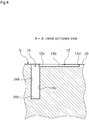
- the dynamic pressure generation groove 15 has a U-shaped cross-section in which both side walls 15c and 15d are orthogonal to a bottom surface 15e and the bottom surface 15e is parallel to the land portion 20.
- the deep groove 16 also has a U-shaped cross-section in which both side walls 16c and 16d are orthogonal to a bottom surface 16e and the bottom surface 16e is parallel to the land portion 20.
- these bottom surfaces 15e and 16e may be inclined with respect to the land portion 20 and these cross-sectional shapes may be, for example, V shapes other than U shapes.
- an inlet 16a of the deep groove 16 communicating with the side of the sealed fluid F communicates with the inlet 15a of the dynamic pressure generation groove 15 in the circumferential direction.
- the closed end 15b of the dynamic pressure generation groove 15 is partitioned by a wall 15f which faces the circumferential direction in a plan view and extends in a direction orthogonal to the sliding surface S and the side walls 15c and 15d which are orthogonal to the sliding surface S.
- the side wall 15d and the wall 15f intersect each other and a tip portion 15h is formed at an acute angle.
- FIGS. 2 and 5 indicate a relative rotation direction of the rotating seal ring 3 which is a mating sliding component.
- the sealed fluid F enters the inlet 15a and the inlet 16a of the deep groove 16 so that the dynamic pressure generation groove 15 and the deep groove 16 are filled with the sealed fluid F.
- the sealed fluid F in the dynamic pressure generation groove 15 flows toward the side wall 15d and the closed end 15b due to a shearing force generated between the sliding surfaces S with the rotation during the relative rotation of the rotating seal ring 3 and the stationary seal ring 6 so that a dynamic pressure is generated in the side wall 15d and the closed end 15b.
- a higher pressure is gradually generated as it goes closer to the tip portion 15h which is most advanced in the movement direction of the sealed fluid F moved with the shearing force generated between the sliding surfaces S and of which the tip faces the movement direction of the sealed fluid F at an acute angle and the sealed fluid F is drawn toward the closed end 15b of the dynamic pressure generation groove 15 (such that the movement direction is indicated by a black arrow).
- a low pressure tends to be generated on the side of the side wall 15c circumferentially opposite to the side wall 15d of the inlet 15a of the dynamic pressure generation groove 15.
- the deep groove 16 which is formed to be deeper than the dynamic pressure generation groove 15 is disposed on the side of the side wall 15c in the circumferential direction of the inlet 15a of the dynamic pressure generation groove 15, the sealed fluid F which is ensured in this deep groove 16 is supplied in the vicinity of the inlet 15a of the dynamic pressure generation groove 15 (as indicated by a white arrow) and hence a negative pressure is not easily generated at that position.
- the sealed fluid F is continuously supplied to the dynamic pressure generation groove 15 so that a high pressure can be generated from the closed end 15b of the dynamic pressure generation groove 15 and the generation of cavitation caused by the insufficient supply amount of the sealed fluid F is suppressed. Accordingly, lubricity is excellent.
- the sealed fluid F is statically supplied from the outside to the deep groove 16 opening to the side of the sealed fluid F through the inlet 16a, the sealed fluid F can be continuously supplied from the deep groove 16 to the vicinity of the inlet 15a of the dynamic pressure generation groove 15.
- the deep groove 16 communicates with the dynamic pressure generation groove 15 which is a shallow groove at a diagonal angle of the tip portion 15h of the closed end 15b of the dynamic pressure generation groove 15. For that reason, the inlet 16a of the deep groove 16 located at a diagonal angle of the tip portion 15h of the closed end 15b generating the highest pressure is a position where the lowest pressure is likely to be generated. As a result, the generation of a small pressure at the inlet 15a of the dynamic pressure generation groove 15 can be suppressed most efficiently and the generation of cavitation due to the insufficient supply amount of the sealed fluid F can be suppressed.
- the deep groove 16 communicates along the dynamic pressure generation groove 15 in the radial direction, the sealed fluid F can be supplied in a wide range in the radial direction to the side circumferentially opposite to the closed end 15b in the inlet 15a of the dynamic pressure generation groove 15 and the generation of a negative pressure can be efficiently prevented.
- the deep groove 16 is formed to be shorter than the dynamic pressure generation groove 15 in the radial direction, the original function of the dynamic pressure generation groove 15 is not easily influenced even when the deep groove 16 is formed while sufficiently ensuring a position of generating a dynamic pressure necessary for the lubricity in the dynamic pressure generation groove 15 in the radial direction.
- the deep groove 16 includes the side walls 16c and 16d extending in parallel in the radial direction and facing each other and the inner space is sandwiched by the side walls 16c and 16d facing each other in the circumferential direction of the sliding surface S, the sealed fluid F is easily held in the deep groove 16 and the sealed fluid F can be stably supplied to the dynamic pressure generation groove 15.
- the width of the inlet 16a of the deep groove 16 is formed to be smaller than the width of the inlet 15a of the dynamic pressure generation groove 15.
- the width of the inlet 16a of the deep groove 16 is preferably a half or less of the width of the inlet 15a of the dynamic pressure generation groove 15 and is about 1/5 in this embodiment.
- the depth of the deep groove 16 is ten times or more the depth of the dynamic pressure generation groove 15.
- the deep groove 16 is a deep groove having a small width, a high pressure is not easily generated by the shearing force between the sliding surfaces S in the entire deep groove 16 since only the sealed fluid F is moved by the shearing force between the sliding surfaces S only on the surface layer thereof when the rotating seal ring 3 and the stationary seal ring 6 rotate relative to each other while ensuring the size of the inner space of the deep groove sufficient for holding the sealed fluid F.
- the deep groove 16 is formed such that the circumferential width is shorter than the radial length. Accordingly, since the deep groove 16 is short in the circumferential direction, a dynamic pressure due to the relative rotation of the rotating seal ring 3 and the stationary seal ring 6 is not easily generated in the deep groove 16 and the sealed fluid F is easily held in the deep groove 16.
- each of the inlet 16a of the deep groove 16 and the inlet 15a of the dynamic pressure generation groove 15 communicates with the side of the sealed fluid F. That is, since the inlet 15a of the dynamic pressure generation groove 15 which is a shallow groove opens to the side of the sealed fluid F so that the sealed fluid F is stably supplied from the deep groove 16 to the dynamic pressure generation groove 15, the dynamic pressure generation groove 15 can be formed with a length sufficient to efficiently generate a high pressure due to the shearing force between the sliding surfaces S.
- the dynamic pressure generation groove 15 is not limited to the linear shape, but may be formed in for example, a curved shape including a component extending in the circumferential direction and a component extending in the radial direction.
- the dynamic pressure generation groove may be formed such that the component extending in the circumferential direction is larger and may be formed to protrude toward the outer circumferential edge side of the stationary seal ring 6.
- the dynamic pressure generation groove 15 may be formed in a shape in which a dynamic pressure is not easily generated at the closed end 15b when driving the rotary machine, the dynamic pressure generation groove may be formed in a linear shape in the radial direction.
- a gas exists on the leakage side of the sliding surface S and a liquid exists on the side of the sealed fluid F, but the present invention is not limited thereto.
- a gas or a liquid may exist in all of the leakage side and the sealed fluid side.
- the sealed fluid F corresponding to the high-pressure fluid exists on the outer circumferential side of the sliding surface S and the atmosphere A corresponding to the low-pressure fluid exists on the inner circumferential side
- the present invention is not limited thereto.
- the fluids existing on the sealed fluid side and the leakage side of the sliding surface S may have the same pressure.
- the deep groove 16 communicates in parallel along the side wall 15c of the dynamic pressure generation groove 15 in the radial direction, but the deep groove 16 is not limited to the above-described configuration if the deep groove is located on the side of the side wall 15c circumferentially opposite to the side wall 15d generating a dynamic pressure in the dynamic pressure generation groove 15.
- the deep groove 26 may include an inlet 26a on the side of a side wall 25c circumferentially opposite to a dynamic pressure generation wall 25d in relation to a center in an inlet of a dynamic pressure generation groove 25 and may be disposed within the width direction of the dynamic pressure generation groove 25.
- the sliding component may be applied to an outside type which is a type that seals a fluid that tends to leak from the inner circumferential side of the sliding surface S toward the outer circumferential side thereof.
- the dynamic pressure generation groove 35 and the deep groove 36 are formed such that the inlet 35a and the inlet 36a communicate with the inner circumferential side of the sliding surface S.
- an inlet 46a of a deep groove 46 communicates with an inlet 45a of a dynamic pressure generation groove 45.
- the deep groove 46 extends in a direction different from the inclined direction of the dynamic pressure generation groove 45 and a closed end 46b and a side wall 46c are formed to be separated from a side wall 45c of the dynamic pressure generation groove 45. Accordingly, since the deep groove 46 and the dynamic pressure generation groove 45 communicate with each other only in the vicinity of the inlet 46a and the inlet 45a, the influence of the movement of the sealed fluid F generated inside the dynamic pressure generation groove 45 during the relative rotation of the rotating seal ring 3 and the stationary seal ring 6 on the inside of the deep groove 46 is small. As a result, the sealed fluid F is easily held in the deep groove 46 and the sealed fluid F can be stably supplied to the dynamic pressure generation groove 45.
- the sliding component of the above-described embodiments constitutes the mechanical seal, but the present invention is not limited thereto.
- the sliding component can be used in a thrust bearing.
- the deep groove is not limited to a configuration in which the width is the same from the inlet to the closed end and may have, for example, a configuration in which the width gradually decreases from the inlet to the closed end.
- the deep groove is not limited to a configuration in which the depth is the same from the inlet to the closed end and may have, for example, a configuration in which the width gradually decreases from the inlet to the closed end.
- a plurality of deep grooves may be formed in the circumferential direction as long as the inlet communicates with the dynamic pressure generation groove.
Landscapes
- Engineering & Computer Science (AREA)
- General Engineering & Computer Science (AREA)
- Mechanical Engineering (AREA)
- Physics & Mathematics (AREA)
- Fluid Mechanics (AREA)
- Mechanical Sealing (AREA)
- Sliding-Contact Bearings (AREA)
Abstract
Description
- The present invention relates to relatively rotating sliding components, for example, sliding components used in a shaft sealing device axially sealing a rotation shaft of a rotary machine in an automobile, a general industrial machine, or other sealing fields or sliding components used in a bearing of a machine in an automobile, a general industrial machine, or other bearing fields.
- Conventionally, as a shaft sealing device that axially seals a rotation shaft of a rotary machine such as a pump or a turbine and prevents a sealed fluid from leaking, one including two components rotating relative to each other so that flat end surfaces slide on each other, for example, a mechanical seal is known. The mechanical seal includes a stationary seal ring which is a sliding component fixed to a housing and a rotating seal ring which is a sliding component fixed to a rotation shaft and rotating together with the rotation shaft and axially seals a gap between the housing and the rotation shaft by relatively rotating these sliding surfaces. In such a mechanical seal, it has been recently desired to reduce energy lost due to sliding for environmental measures and sliding components such as Patent Citation 1 have been developed to reduce the energy lost due to sliding by reducing friction caused by sliding.
- For example, the sliding component shown in
Patent Citation 1 is provided with a dynamic pressure generation groove of which one end forms an inlet and communicates with an outer radial side corresponding to a high-pressure sealed liquid side in a sliding surface of the sliding component and the other end in the sliding surface forms a closed end. Accordingly, when the sliding components rotate relative to each other, since a sealed fluid flowing from the inlet into the dynamic pressure generation groove flows out from the closed end of the dynamic pressure generation groove to a gap between the sliding surfaces, the sliding surfaces are separated from each other by a dynamic pressure. At the same time, since the dynamic pressure generation groove holds the sealed liquid, lubricity is improved. As a result, low friction is realized. - Patent Citation 1:
JP 6444492 B2 Page 5,FIG. 2 ) - In the sliding component shown in
Patent Citation 1, when the sliding components rotate relative to each other, the sealed fluid in the dynamic pressure generation groove flows toward one (hereinafter, referred to as a "dynamic pressure generation wall") of both side walls constituting the dynamic pressure generation groove due to a shearing force generated between the sliding surfaces with the rotation so that a high pressure (dynamic pressure) is generated in the dynamic pressure generation wall. Then, this pressure gradually becomes higher toward the closed end and a low pressure is likely to be generated particularly on the side of the side wall circumferentially opposite to the dynamic pressure generation wall in the inlet of the dynamic pressure generation groove. In this way, when the pressure in the vicinity of the inlet of the dynamic pressure generation groove decreases so that a negative pressure is generated, the sealed fluid is not easily introduced from the inlet of the dynamic pressure generation groove. Accordingly, since a desired pressure is not generated from the dynamic pressure generation wall and the closed end of the dynamic pressure generation groove and a sufficient pressure is not generated, lubricity is deteriorated. Further, when a negative pressure is generated and cavitation is generated in the vicinity of the inlet of the dynamic pressure generation groove, it is remarkably difficult to introduce the sealed fluid from the inlet of the dynamic pressure generation groove. - The present invention has been made in view of such problems and an object of the present invention is to provide a sliding component having excellent lubricity.
- In order to solve the foregoing problems, a sliding component according to the present invention is a sliding component formed in an annular shape and disposed at a relatively rotating position of a rotary machine, the sliding component including: a dynamic pressure generation groove provided in a sliding surface of the sliding component, the dynamic pressure generation groove having a first end forming a closed end and a second end forming an inlet communicating with any one side of a sealed fluid side and a leakage side in a radial direction; and a deep groove provided in the sliding surface and deeper than the dynamic pressure generation groove, an inlet of the deep groove communicating with an inlet of the dynamic pressure generation groove on a side of a side wall of the dynamic pressure generation groove, the side wall being circumferentially opposite to a dynamic pressure generation wall constituting another side wall of the dynamic pressure generation groove. According to the aforesaid feature of the present invention, since a position where the lowest pressure is likely to be generated in the dynamic pressure generation groove during the relative rotation of the sliding components is on the side of the side wall circumferentially opposite to the dynamic pressure generation wall constituting one of both side walls constituting the dynamic pressure generation groove in the inlet of the dynamic pressure generation groove and the inlet of the deep groove communicates with this position, a fluid is sufficiently supplied from this deep groove to the dynamic pressure generation groove and hence a negative pressure is not easily generated at the corresponding position. As a result, the fluid is continuously supplied to the dynamic pressure generation groove and a desired pressure can be generated from the closed end of the dynamic pressure generation groove. Accordingly, lubricity is excellent.
- It may be preferable that the deep groove communicates with the dynamic pressure generation groove along the side wall circumferentially opposite to the dynamic pressure generation wall of the dynamic pressure generation groove in the radial direction and is shorter than the side wall in the radial direction. According to this preferable configuration, a wide inflow area from the deep groove to the dynamic pressure generation groove can be ensured while the deep groove does not easily influence the function of generating the dynamic pressure of the dynamic pressure generation groove.
- It may be preferable that the deep groove includes a pair of wall portions extending in parallel radially and facing each other. According to this preferable configuration, since the inner space of the deep groove is sandwiched by the facing wall portions in the circumferential direction of the sliding surface, the sealed fluid is easily held in the deep groove and the sealed fluid can be stably supplied to the dynamic pressure generation groove.
- It may be preferable that the deep groove is formed such that a circumferential width of the deep groove is shorter than a radial length of the deep groove. According to this preferable configuration, since the deep groove is short in the circumferential direction, a dynamic pressure is not easily generated by the relative rotation of the sliding components in the deep groove and the sealed fluid is easily held in the deep groove.
- It may be preferable that a width of the inlet of the deep groove is half or less of a width of the inlet of the dynamic pressure generation groove. According to this preferable configuration, it is possible to reliably introduce the sealed fluid into the dynamic pressure generation groove and suppress a negative pressure from being generated in the vicinity of the inlet of the dynamic pressure generation groove at the same time during the relative rotation of the sliding components.
- It may be preferable that a depth of the deep groove is ten times or more a depth of the dynamic pressure generation groove. According to this preferable configuration, the volume of the deep groove is large and a sufficient amount of the sealed fluid is supplied from the deep groove to the dynamic pressure generation groove during the relative rotation of the sliding components.
- In addition, the expression of extending in the radial direction according to the present invention may also have a circumferential component as long as there is at least a radial component.
-
-
FIG. 1 is a cross-sectional view illustrating a structure of a rotary machine that uses a mechanical seal including sliding components according to a first embodiment of the present invention. -
FIG. 2 is a view in which a stationary seal ring is viewed from a sliding surface side in the first embodiment. -
FIG. 3 is a perspective view in which a dynamic pressure generation groove and a deep groove are viewed from an inlet side in the first embodiment. -
FIG. 4 is a cross-sectional view taken along a line A-A ofFIG. 2 illustrating a relationship between the dynamic pressure generation groove and the deep groove in the first embodiment. -
FIG. 5 is a conceptual diagram illustrating a movement of a fluid during a rotation of a rotary machine in the first embodiment. -
FIG. 6 is a main enlarged view in which a stationary seal ring of a first modified example in the first embodiment is viewed from a sliding surface side. -
FIG. 7 is a view in which a stationary seal ring of a second modified example in the first embodiment is viewed from a sliding surface side. -
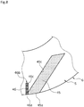
FIG. 8 is a main enlarged view in which a stationary seal ring as a sliding component according to a second embodiment of the present invention is viewed from a sliding surface side. - Modes for implementing a sliding component according to the present invention will be described below based on embodiments.
- Sliding components according to a first embodiment of the present invention will be described with reference to
FIGS. 1 to 5 . - The sliding components of this embodiment are, for example, a rotating
seal ring 3 and astationary seal ring 6 constituting a mechanical seal which is a shaft sealing device axially sealing a rotation shaft of a rotary machine in an automobile, a general industrial machine, or other sealing fields. Further, for convenience of description, dots may be added to grooves and the like formed on a sliding surface in the drawings. - As illustrated in
FIG. 1 , a mechanical seal of this embodiment is of an inside type that seals a sealed fluid that tends to leak from a sealed fluid side which is an outer circumferential side of a sliding surface toward a leakage side which is an inner circumferential side and an annular rotatingseal ring 3 which is provided on the side of arotation shaft 1 through asleeve 2 to be rotatable together with therotation shaft 1 and an annularstationary seal ring 6 which is provided in aseal cover 5 fixed to ahousing 4 of a rotary machine not to be rotatable and to be axially movable are configured such that sliding surfaces S slide on each other in a close contact state by a biasingmember 7 axially biasing thestationary seal ring 6. That is, this mechanical seal is for preventing a sealed fluid F which is a high-pressure fluid on the outer circumferential side of the sliding surface S from leaking to the inner circumferential side which is the leakage side where an atmosphere A which is a low-pressure fluid exists in the sliding surface S between the rotatingseal ring 3 and the stationary seal ring 6 (seeFIG. 2 ). In this embodiment, the sealed fluid F is a liquid. - The rotating
seal ring 3 and thestationary seal ring 6 are typically formed of SiC (as an example of hard material) or a combination of SiC (as the example of hard material) and carbon (as an example of soft material), but any sliding material is applicable as long as the sliding material is used as the sliding material for the mechanical seal. Examples of SiC include a sintered body using boron, aluminum, carbon, and the like as a sintering aid and materials composed of two or more types of phases having different components and compositions, for example, SiC obtained by dispersing graphite particles, reaction sintered SiC composed of SiC and Si, SiC-TiC, SiC-TiN, and the like and examples of carbon include carbon obtained by mixing carbon materials and graphite materials, resin molded carbon, sintered carbon, and the like. In addition to the above sliding materials, metal materials, resin materials, surface modification materials (e.g., coating materials), composite materials, and the like can also be applied. - As illustrated in
FIG. 2 , the sliding surface S of thestationary seal ring 6 is provided with a plurality of dynamicpressure generation grooves 15 which are arranged in the circumferential direction and are separated from each other in the circumferential direction. The dynamicpressure generation grooves 15 are formed side by side with the same separation width in the circumferential direction. The dynamicpressure generation groove 15 can be formed by subjecting the mirror-processed sliding surface S to fine processing such as laser processing or sandblasting. A portion not provided with the dynamicpressure generation groove 15 and adeep groove 16 to be described later in the sliding surface S is aland portion 20 forming a flat surface. - As illustrated in
FIGS. 2 to 4 , the dynamicpressure generation groove 15 is formed such that one end forms aninlet 15a communicating with the side of the sealed fluid F and the other end forms a closedend 15b and is obliquely formed in the rotation direction to generate a dynamic pressure on the side of the closedend 15b during the relative rotation of the rotatingseal ring 3 and thestationary seal ring 6. Further, the dynamicpressure generation grooves 15 are formed to have the same depth in the radial direction. In the dynamicpressure generation groove 15, the sealed fluid F flows in the dynamicpressure generation groove 15 toward oneside wall 15d in the right andleft side walls pressure generation groove 15 due to a shearing force generated between the sliding surfaces S with the rotation during the relative rotation of the rotatingseal ring 3 and thestationary seal ring 6 so that a high pressure, that is, a dynamic pressure is generated in theside wall 15d which is the dynamic pressure generation wall. - The
deep groove 16 is located on the side opposite to the closedend 15b in the circumferential direction with respect to the dynamicpressure generation groove 15 and communicates with the dynamicpressure generation groove 15 in the circumferential direction. Specifically, aside wall 16c on the side of the dynamicpressure generation groove 15 in the right and left side walls of thedeep groove 16 is located on the side of theside wall 15c circumferentially opposite to theside wall 15d which is the dynamic pressure generation wall on the side opposite to thedeep groove 16 in the right andleft side walls pressure generation groove 15. That is, as illustrated inFIG. 2 , thedeep groove 16 is formed to partially overlap the dynamicpressure generation groove 15 in the circumferential direction when viewed from a plane orthogonal to the sliding surface S. - Further, as illustrated in
FIG. 3 , the dynamicpressure generation groove 15 has a U-shaped cross-section in which bothside walls bottom surface 15e and thebottom surface 15e is parallel to theland portion 20. Similarly, thedeep groove 16 also has a U-shaped cross-section in which bothside walls bottom surface 16e and thebottom surface 16e is parallel to theland portion 20. In addition, thesebottom surfaces land portion 20 and these cross-sectional shapes may be, for example, V shapes other than U shapes. - Further, an
inlet 16a of thedeep groove 16 communicating with the side of the sealed fluid F communicates with theinlet 15a of the dynamicpressure generation groove 15 in the circumferential direction. - Further, as illustrated in
FIG. 2 , theclosed end 15b of the dynamicpressure generation groove 15 is partitioned by awall 15f which faces the circumferential direction in a plan view and extends in a direction orthogonal to the sliding surface S and theside walls closed end 15b, theside wall 15d and thewall 15f intersect each other and atip portion 15h is formed at an acute angle. - Next, a function of the dynamic
pressure generation groove 15 and thedeep groove 16 during the relative rotation of therotating seal ring 3 and thestationary seal ring 6 will be described with reference toFIG. 5 . In addition, an arrow inFIGS. 2 and5 indicates a relative rotation direction of therotating seal ring 3 which is a mating sliding component. - As a premise, when the rotary machine is stopped, the sealed fluid F enters the
inlet 15a and theinlet 16a of thedeep groove 16 so that the dynamicpressure generation groove 15 and thedeep groove 16 are filled with the sealed fluid F. As illustrated inFIG. 5 , the sealed fluid F in the dynamicpressure generation groove 15 flows toward theside wall 15d and theclosed end 15b due to a shearing force generated between the sliding surfaces S with the rotation during the relative rotation of therotating seal ring 3 and thestationary seal ring 6 so that a dynamic pressure is generated in theside wall 15d and theclosed end 15b. - At this time, in the dynamic
pressure generation groove 15, a higher pressure is gradually generated as it goes closer to thetip portion 15h which is most advanced in the movement direction of the sealed fluid F moved with the shearing force generated between the sliding surfaces S and of which the tip faces the movement direction of the sealed fluid F at an acute angle and the sealed fluid F is drawn toward theclosed end 15b of the dynamic pressure generation groove 15 (such that the movement direction is indicated by a black arrow). As a result, a low pressure tends to be generated on the side of theside wall 15c circumferentially opposite to theside wall 15d of theinlet 15a of the dynamicpressure generation groove 15. - Here, since the
deep groove 16 which is formed to be deeper than the dynamicpressure generation groove 15 is disposed on the side of theside wall 15c in the circumferential direction of theinlet 15a of the dynamicpressure generation groove 15, the sealed fluid F which is ensured in thisdeep groove 16 is supplied in the vicinity of theinlet 15a of the dynamic pressure generation groove 15 (as indicated by a white arrow) and hence a negative pressure is not easily generated at that position. - For that reason, the sealed fluid F is continuously supplied to the dynamic
pressure generation groove 15 so that a high pressure can be generated from theclosed end 15b of the dynamicpressure generation groove 15 and the generation of cavitation caused by the insufficient supply amount of the sealed fluid F is suppressed. Accordingly, lubricity is excellent. - Further, since the sealed fluid F is statically supplied from the outside to the
deep groove 16 opening to the side of the sealed fluid F through theinlet 16a, the sealed fluid F can be continuously supplied from thedeep groove 16 to the vicinity of theinlet 15a of the dynamicpressure generation groove 15. - Further, the
deep groove 16 communicates with the dynamicpressure generation groove 15 which is a shallow groove at a diagonal angle of thetip portion 15h of theclosed end 15b of the dynamicpressure generation groove 15. For that reason, theinlet 16a of thedeep groove 16 located at a diagonal angle of thetip portion 15h of theclosed end 15b generating the highest pressure is a position where the lowest pressure is likely to be generated. As a result, the generation of a small pressure at theinlet 15a of the dynamicpressure generation groove 15 can be suppressed most efficiently and the generation of cavitation due to the insufficient supply amount of the sealed fluid F can be suppressed. - Further, since the
deep groove 16 communicates along the dynamicpressure generation groove 15 in the radial direction, the sealed fluid F can be supplied in a wide range in the radial direction to the side circumferentially opposite to theclosed end 15b in theinlet 15a of the dynamicpressure generation groove 15 and the generation of a negative pressure can be efficiently prevented. In addition, since thedeep groove 16 is formed to be shorter than the dynamicpressure generation groove 15 in the radial direction, the original function of the dynamicpressure generation groove 15 is not easily influenced even when thedeep groove 16 is formed while sufficiently ensuring a position of generating a dynamic pressure necessary for the lubricity in the dynamicpressure generation groove 15 in the radial direction. - Further, since the
deep groove 16 includes theside walls side walls deep groove 16 and the sealed fluid F can be stably supplied to the dynamicpressure generation groove 15. - Further, the width of the
inlet 16a of thedeep groove 16 is formed to be smaller than the width of theinlet 15a of the dynamicpressure generation groove 15. Specifically, the width of theinlet 16a of thedeep groove 16 is preferably a half or less of the width of theinlet 15a of the dynamicpressure generation groove 15 and is about 1/5 in this embodiment. In addition, the depth of thedeep groove 16 is ten times or more the depth of the dynamicpressure generation groove 15. Accordingly, since thedeep groove 16 is a deep groove having a small width, a high pressure is not easily generated by the shearing force between the sliding surfaces S in the entiredeep groove 16 since only the sealed fluid F is moved by the shearing force between the sliding surfaces S only on the surface layer thereof when therotating seal ring 3 and thestationary seal ring 6 rotate relative to each other while ensuring the size of the inner space of the deep groove sufficient for holding the sealed fluid F. - Further, as understood from
FIG. 2 , thedeep groove 16 is formed such that the circumferential width is shorter than the radial length. Accordingly, since thedeep groove 16 is short in the circumferential direction, a dynamic pressure due to the relative rotation of therotating seal ring 3 and thestationary seal ring 6 is not easily generated in thedeep groove 16 and the sealed fluid F is easily held in thedeep groove 16. - Further, each of the
inlet 16a of thedeep groove 16 and theinlet 15a of the dynamicpressure generation groove 15 communicates with the side of the sealed fluid F. That is, since theinlet 15a of the dynamicpressure generation groove 15 which is a shallow groove opens to the side of the sealed fluid F so that the sealed fluid F is stably supplied from thedeep groove 16 to the dynamicpressure generation groove 15, the dynamicpressure generation groove 15 can be formed with a length sufficient to efficiently generate a high pressure due to the shearing force between the sliding surfaces S. - Additionally, in the above-described embodiment, a case has been described in which the dynamic
pressure generation groove 15 and thedeep groove 16 formed on the sliding surface S of thestationary seal ring 6, but the present invention is not limited thereto. For example, these grooves may be formed on the sliding surface S of therotating seal ring 3. - Additionally, the dynamic
pressure generation groove 15 is not limited to the linear shape, but may be formed in for example, a curved shape including a component extending in the circumferential direction and a component extending in the radial direction. Here, the dynamic pressure generation groove may be formed such that the component extending in the circumferential direction is larger and may be formed to protrude toward the outer circumferential edge side of thestationary seal ring 6. - Additionally, since the dynamic
pressure generation groove 15 may be formed in a shape in which a dynamic pressure is not easily generated at theclosed end 15b when driving the rotary machine, the dynamic pressure generation groove may be formed in a linear shape in the radial direction. - Additionally, in the above-described embodiment, a case has been described in which a gas exists on the leakage side of the sliding surface S and a liquid exists on the side of the sealed fluid F, but the present invention is not limited thereto. For example, a gas or a liquid may exist in all of the leakage side and the sealed fluid side.
- Further, in the above-described embodiment, a case has been described in which the sealed fluid F corresponding to the high-pressure fluid exists on the outer circumferential side of the sliding surface S and the atmosphere A corresponding to the low-pressure fluid exists on the inner circumferential side, but the present invention is not limited thereto. For example, the fluids existing on the sealed fluid side and the leakage side of the sliding surface S may have the same pressure.
- Additionally, in the above-described embodiment, the
deep groove 16 communicates in parallel along theside wall 15c of the dynamicpressure generation groove 15 in the radial direction, but thedeep groove 16 is not limited to the above-described configuration if the deep groove is located on the side of theside wall 15c circumferentially opposite to theside wall 15d generating a dynamic pressure in the dynamicpressure generation groove 15. - For example, as in a first modified example illustrated in
FIG. 6 , thedeep groove 26 may include aninlet 26a on the side of aside wall 25c circumferentially opposite to a dynamicpressure generation wall 25d in relation to a center in an inlet of a dynamicpressure generation groove 25 and may be disposed within the width direction of the dynamicpressure generation groove 25. - Further, as in a second modified example illustrated in
FIG. 7 , the sliding component may be applied to an outside type which is a type that seals a fluid that tends to leak from the inner circumferential side of the sliding surface S toward the outer circumferential side thereof. In this case, the dynamicpressure generation groove 35 and thedeep groove 36 are formed such that theinlet 35a and theinlet 36a communicate with the inner circumferential side of the sliding surface S. - Next, sliding components according to a second embodiment of the present invention will be described with reference to
FIG. 8 . In addition, a description for the overlapping configuration in the same configuration as that of the above-described embodiment will be omitted. - As illustrated in
FIG. 8 , aninlet 46a of adeep groove 46 communicates with aninlet 45a of a dynamicpressure generation groove 45. Further, thedeep groove 46 extends in a direction different from the inclined direction of the dynamicpressure generation groove 45 and aclosed end 46b and aside wall 46c are formed to be separated from aside wall 45c of the dynamicpressure generation groove 45. Accordingly, since thedeep groove 46 and the dynamicpressure generation groove 45 communicate with each other only in the vicinity of theinlet 46a and theinlet 45a, the influence of the movement of the sealed fluid F generated inside the dynamicpressure generation groove 45 during the relative rotation of therotating seal ring 3 and thestationary seal ring 6 on the inside of thedeep groove 46 is small. As a result, the sealed fluid F is easily held in thedeep groove 46 and the sealed fluid F can be stably supplied to the dynamicpressure generation groove 45. - Although the embodiments of the present invention have been described with reference to the drawings, the specific configuration is not limited to these embodiments and any changes or additions that do not deviate from the gist of the present invention are included in the present invention.
- For example, a case has been described in which the sliding component of the above-described embodiments constitutes the mechanical seal, but the present invention is not limited thereto. For example, the sliding component can be used in a thrust bearing.
- Further, the deep groove is not limited to a configuration in which the width is the same from the inlet to the closed end and may have, for example, a configuration in which the width gradually decreases from the inlet to the closed end.
- Further, the deep groove is not limited to a configuration in which the depth is the same from the inlet to the closed end and may have, for example, a configuration in which the width gradually decreases from the inlet to the closed end.
- Further, a plurality of deep grooves may be formed in the circumferential direction as long as the inlet communicates with the dynamic pressure generation groove.
-
- 1
- Rotation shaft
- 2
- Sleeve
- 3
- Rotating seal ring (sliding component)
- 4
- Housing
- 5
- Seal cover
- 6
- Stationary seal ring (sliding component)
- 7
- Biasing member
- 11
- Inlet
- 15
- Dynamic pressure generation groove
- 15a
- Dynamic pressure generation groove inlet
- 15b
- Closed end
- 15c
- Side wall
- 15d
- Side wall (dynamic pressure generation wall)
- 15e
- Bottom surface
- 15f
- Wall
- 15h
- Tip portion
- 16
- Deep groove
- 16a
- Deep groove inlet
- 16b
- Closed end
- 16c
- Side wall
- 16d
- Side wall
- 16e
- Bottom surface
- 20
- Land portion
- 25
- Dynamic pressure generation groove
- 26
- Deep groove
- 35
- Dynamic pressure generation groove
- 36
- Deep groove
- 45
- Dynamic pressure generation groove
- 46
- Deep groove
- 46b
- Closed end
- S
- Sliding surface
Claims (6)
- A sliding component formed in an annular shape and disposed at a relatively rotating position of a rotary machine,the sliding component comprising: a dynamic pressure generation groove provided in a sliding surface of the sliding component, the dynamic pressure generation groove having a first end forming a closed end and a second end forming an inlet communicating with any one side of a sealed fluid side and a leakage side in a radial direction; anda deep groove provided in the sliding surface and deeper than the dynamic pressure generation groove, an inlet of the deep groove communicating with an inlet of the dynamic pressure generation groove on a side of a side wall of the dynamic pressure generation groove, the side wall being circumferentially opposite to a dynamic pressure generation wall constituting another side wall of the dynamic pressure generation groove.
- The sliding component according to claim 1,
wherein the deep groove communicates with the dynamic pressure generation groove along the side wall circumferentially opposite to the dynamic pressure generation wall of the dynamic pressure generation groove in the radial direction and is shorter than the side wall in the radial direction. - The sliding component according to claim 1 or 2,
wherein the deep groove includes wall portions extending radially and facing each other. - The sliding component according to any one of claims 1 to 3,
wherein the deep groove is formed such that a circumferential width of the deep groove is shorter than a radial length of the deep groove. - The sliding component according to any one of claims 1 to 4,
wherein a width of the inlet of the deep groove is half or less of a width of the inlet of the dynamic pressure generation groove. - The sliding component according to any one of claims 1 to 5,
wherein a depth of the deep groove is ten times or more a depth of the dynamic pressure generation groove.
Applications Claiming Priority (2)
| Application Number | Priority Date | Filing Date | Title |
|---|---|---|---|
| JP2019024901 | 2019-02-14 | ||
| PCT/JP2020/005260 WO2020166590A1 (en) | 2019-02-14 | 2020-02-12 | Sliding component |
Publications (4)
| Publication Number | Publication Date |
|---|---|
| EP3926186A1 true EP3926186A1 (en) | 2021-12-22 |
| EP3926186A4 EP3926186A4 (en) | 2022-11-16 |
| EP3926186C0 EP3926186C0 (en) | 2024-08-21 |
| EP3926186B1 EP3926186B1 (en) | 2024-08-21 |
Family
ID=72045557
Family Applications (1)
| Application Number | Title | Priority Date | Filing Date |
|---|---|---|---|
| EP20756664.7A Active EP3926186B1 (en) | 2019-02-14 | 2020-02-12 | Sliding component |
Country Status (6)
| Country | Link |
|---|---|
| US (1) | US11933405B2 (en) |
| EP (1) | EP3926186B1 (en) |
| JP (1) | JP7370681B2 (en) |
| KR (1) | KR102639196B1 (en) |
| CN (2) | CN117432709A (en) |
| WO (1) | WO2020166590A1 (en) |
Families Citing this family (3)
| Publication number | Priority date | Publication date | Assignee | Title |
|---|---|---|---|---|
| JP7809645B2 (en) * | 2020-09-29 | 2026-02-02 | イーグル工業株式会社 | Sliding parts |
| EP4502432A4 (en) * | 2022-03-24 | 2026-02-25 | Eagle Ind Co Ltd | SLIDING COMPONENT |
| US20250223972A1 (en) * | 2024-01-05 | 2025-07-10 | John Crane Inc. | Drive ring for rotary shaft equipment seals |
Family Cites Families (182)
| Publication number | Priority date | Publication date | Assignee | Title |
|---|---|---|---|---|
| JPS366305B1 (en) | 1960-03-31 | 1961-05-30 | ||
| US3085808A (en) | 1960-05-17 | 1963-04-16 | Worthington Corp | Mechanical seal with controlled leakage |
| US3232680A (en) | 1963-08-19 | 1966-02-01 | Whittaker Corp | Fluid bearing |
| US3410565A (en) | 1966-07-27 | 1968-11-12 | Worthington Corp | Centrifugal and face contact seal |
| FR1505487A (en) | 1966-10-28 | 1967-12-15 | Guinard Pompes | Improvement in leak-controlled rotary joints |
| US3466052A (en) | 1968-01-25 | 1969-09-09 | Nasa | Foil seal |
| US3499653A (en) | 1968-06-05 | 1970-03-10 | Crane Packing Co | Rotary mechanical seal of the gap type |
| US3656227A (en) | 1970-03-26 | 1972-04-18 | Gen Motors Corp | Method of making a mold for bidirectional hydrodynamic shaft seals |
| US3782737A (en) | 1970-07-13 | 1974-01-01 | Nasa | Spiral groove seal |
| US3675935A (en) | 1970-07-13 | 1972-07-11 | Nasa | Spiral groove seal |
| US3804424A (en) | 1972-04-24 | 1974-04-16 | Crane Packing Co | Gap seal with thermal and pressure distortion compensation |
| JPS4933614A (en) | 1972-07-24 | 1974-03-28 | ||
| NL7213192A (en) | 1972-09-29 | 1974-04-02 | ||
| US3855624A (en) | 1973-08-15 | 1974-12-17 | Philips Corp | Grooved air bearing head |
| DE2504204C3 (en) | 1975-02-01 | 1981-11-12 | Skf Kugellagerfabriken Gmbh, 8720 Schweinfurt | Self-pressure generating axial slide bearing |
| JPS5271858U (en) | 1975-11-25 | 1977-05-28 | ||
| JPS5477305A (en) | 1977-12-02 | 1979-06-20 | Hitachi Constr Mach Co Ltd | Compound pump motor |
| JPS5724220A (en) | 1980-07-21 | 1982-02-08 | Dainippon Printing Co Ltd | Mold device for injection molding |
| JPS57146955A (en) | 1981-03-06 | 1982-09-10 | Shinsaku Kaguchi | Sealing device for rotary member |
| JPS58109771A (en) | 1981-12-23 | 1983-06-30 | Eagle Ind Co Ltd | Non-contact type mechanical seal |
| JPS58137667A (en) | 1982-02-10 | 1983-08-16 | Nippon Seiko Kk | magnetic fluid seal |
| US4486026A (en) | 1982-02-10 | 1984-12-04 | Nippon Seiko K.K. | Sealing and bearing means by use of ferrofluid |
| DE3223703C2 (en) | 1982-06-25 | 1984-05-30 | M.A.N. Maschinenfabrik Augsburg-Nürnberg AG, 4200 Oberhausen | Gas-locked shaft seal with radial sealing gap |
| JPS5958252A (en) | 1982-09-29 | 1984-04-03 | Honda Motor Co Ltd | V belt transmission device |
| US4406466A (en) | 1982-11-29 | 1983-09-27 | Elliott Turbomachinery Co., Inc. | Gas lift bearing and oil seal |
| JPS60107461A (en) | 1983-11-15 | 1985-06-12 | Jidosha Kiki Co Ltd | Method of controlling power steering device |
| JPH06100642B2 (en) | 1984-09-29 | 1994-12-12 | 株式会社東芝 | Optical applied magnetic field sensor |
| US4645414A (en) | 1985-06-07 | 1987-02-24 | General Motors Corporation | Combined vacuum pump, bearing and seal assembly |
| JPS6237572A (en) | 1985-08-12 | 1987-02-18 | Ebara Res Co Ltd | Shaft seal device |
| DE3619489A1 (en) | 1986-06-10 | 1987-12-17 | Gutehoffnungshuette Man | SHAFT SEAL |
| JPS6333027A (en) | 1986-07-28 | 1988-02-12 | Nippon Hoso Kyokai <Nhk> | Sound digital signal transmission system |
| CH677266A5 (en) | 1986-10-28 | 1991-04-30 | Pacific Wietz Gmbh & Co Kg | |
| US5246295A (en) | 1991-10-30 | 1993-09-21 | Ide Russell D | Non-contacting mechanical face seal of the gap-type |
| JPH0620155Y2 (en) | 1987-09-11 | 1994-05-25 | シチズン時計株式会社 | Clock time adjustment mechanism |
| JPH01133572A (en) | 1987-11-16 | 1989-05-25 | Sanyo Electric Co Ltd | Single-phase frequency conversion circuit |
| JPH06105105B2 (en) | 1989-03-03 | 1994-12-21 | 日本ピラー工業株式会社 | Non-contact end face mechanical seal |
| GB2231105B (en) | 1989-04-24 | 1993-04-14 | Sealol | Drained face seal |
| JPH0314371A (en) | 1989-06-13 | 1991-01-23 | Fuji Photo Film Co Ltd | Image oscillation correcting device for video camera |
| JPH0335372A (en) | 1989-06-30 | 1991-02-15 | Mita Ind Co Ltd | Image deciding device |
| JP2554542B2 (en) | 1989-07-06 | 1996-11-13 | 株式会社 藤井合金製作所 | Gas cock manufacturing method |
| JPH0341267A (en) | 1989-07-07 | 1991-02-21 | Mitsuwa Gas Kiki Kk | Manufacture of cast iron gas cock |
| JPH0660691B2 (en) | 1990-04-17 | 1994-08-10 | イーグル工業株式会社 | Double rotation type semi-contact mechanical seal and groove machining method for ring sliding surface |
| US5492341A (en) | 1990-07-17 | 1996-02-20 | John Crane Inc. | Non-contacting, gap-type seal having a ring with a patterned seal face |
| JPH0496671A (en) | 1990-08-11 | 1992-03-30 | Omron Corp | Harmonic drive electrostatic motor |
| JPH04145267A (en) | 1990-10-08 | 1992-05-19 | Ebara Corp | Noncontact end-face seal |
| GB9103217D0 (en) | 1991-02-15 | 1991-04-03 | Crane John Uk Ltd | Mechanical face seals |
| JPH0590048A (en) | 1991-09-25 | 1993-04-09 | Nissin Electric Co Ltd | Voltage transformer for insulating gas-filled switchgear |
| US5447316A (en) | 1992-02-06 | 1995-09-05 | Eagle Industry Co., Ltd. | Gas seal |
| US5201531A (en) | 1992-04-02 | 1993-04-13 | John Crane Inc. | Face seal with double spiral grooves |
| JPH0769019B2 (en) | 1992-05-18 | 1995-07-26 | 日本ピラー工業株式会社 | Non-contact mechanical seal |
| GB9214282D0 (en) | 1992-07-04 | 1992-08-19 | Crane John Uk Ltd | Seals |
| US5501470A (en) | 1992-12-11 | 1996-03-26 | Nippon Pillar Packing Co., Ltd. | Non-contacting shaft sealing device with grooved face pattern |
| US5441283A (en) | 1993-08-03 | 1995-08-15 | John Crane Inc. | Non-contacting mechanical face seal |
| AU685502B2 (en) | 1993-09-01 | 1998-01-22 | Durametallic Corporation | Face seal with angled and annular grooves |
| JP3337289B2 (en) * | 1993-11-15 | 2002-10-21 | 三菱重工業株式会社 | Hydrodynamic bearing |
| US5498007A (en) | 1994-02-01 | 1996-03-12 | Durametallic Corporation | Double gas barrier seal |
| DE4407453A1 (en) | 1994-03-05 | 1995-09-07 | Albrecht Dipl Ing Kayser | Thrust bearing with helix grooves for oil and gas sealing |
| JP2563081B2 (en) | 1994-03-22 | 1996-12-11 | 日本ピラー工業株式会社 | Non-contact type shaft sealing device |
| JP3387236B2 (en) | 1994-09-22 | 2003-03-17 | 株式会社島津製作所 | Biomagnetic measurement device |
| JPH09329247A (en) | 1996-06-11 | 1997-12-22 | Ebara Corp | Non-contact end surface seal |
| JP2999415B2 (en) | 1996-07-24 | 2000-01-17 | 日本ピラー工業株式会社 | mechanical seal |
| JPH10281299A (en) | 1997-04-11 | 1998-10-23 | Mitsubishi Heavy Ind Ltd | Mechanical seal device |
| US5895051A (en) | 1997-07-16 | 1999-04-20 | Freudenberg-Nok General Partnership | Noise abating beads on a rack seal |
| JPH1151043A (en) | 1997-08-05 | 1999-02-23 | Seiko Instr Inc | Fluid dynamic pressure bearing, spindle motor having this bearing, and rotating body device provided with this motor |
| US6142478A (en) | 1998-02-06 | 2000-11-07 | John Crane Inc. | Gas lubricated slow speed seal |
| PL187630B1 (en) | 1998-12-10 | 2004-08-31 | Anga Uszczelnienia Mechaniczne | Contactless mechanical end-face seal |
| JP4075170B2 (en) | 1998-12-17 | 2008-04-16 | 松下電器産業株式会社 | Hydrodynamic bearing device and spindle motor using the same |
| US6189896B1 (en) | 1999-04-08 | 2001-02-20 | Caterpillar Inc. | Controlled leakage rotating seal ring with elements for receiving and holding a lubricant on a face thereof |
| JP2001295833A (en) | 2000-04-18 | 2001-10-26 | Matsushita Electric Ind Co Ltd | Thrust hydrodynamic bearing |
| JP2001317638A (en) | 2000-05-02 | 2001-11-16 | Mitsubishi Heavy Ind Ltd | Seal structure and compressor |
| US7044470B2 (en) | 2000-07-12 | 2006-05-16 | Perkinelmer, Inc. | Rotary face seal assembly |
| US6446976B1 (en) | 2000-09-06 | 2002-09-10 | Flowserve Management Company | Hydrodynamic face seal with grooved sealing dam for zero-leakage |
| CN2460801Y (en) | 2001-01-18 | 2001-11-21 | 王玉明 | Sealing device for spiral flute end capable of bidirectional rotation |
| CN1167890C (en) | 2001-01-18 | 2004-09-22 | 王玉明 | Spiral groove end sealer capable of being rotated in both directions |
| JP3984462B2 (en) | 2001-11-26 | 2007-10-03 | 日本電産株式会社 | Hydrodynamic bearing device |
| CN2534429Y (en) | 2001-12-27 | 2003-02-05 | 中国石油天然气股份有限公司 | Dual-row co-directional hydrodynamic groove upstream pumping mechanical seal |
| JP4495402B2 (en) | 2002-03-19 | 2010-07-07 | イーグル工業株式会社 | Sliding parts |
| US6902168B2 (en) | 2002-03-19 | 2005-06-07 | Eagle Industry Co., Ltd. | Sliding element |
| JP4205910B2 (en) | 2002-04-02 | 2009-01-07 | イーグル工業株式会社 | Sliding parts |
| AU2003252052A1 (en) | 2002-07-18 | 2004-02-09 | University Of Washington | Rapid, efficient purification of hsv-specific t-lymphocytes and hsv antigens identified via same |
| CN100427816C (en) | 2002-09-20 | 2008-10-22 | 徐万福 | Helical flute and face mechanial seal composed of angular microflute group |
| JP4316956B2 (en) | 2002-10-23 | 2009-08-19 | イーグル工業株式会社 | Sliding parts |
| US7540664B2 (en) | 2003-01-21 | 2009-06-02 | Seagate Technology Llc | Grooves on both the moving and the stationary mating fluid dynamic bearing surfaces for performance enhancement |
| JP4188177B2 (en) | 2003-08-08 | 2008-11-26 | 株式会社共立 | Portable brush cutter |
| US7160031B2 (en) | 2003-11-20 | 2007-01-09 | Matsushita Electric Industrial Co., Ltd. | Thrust dynamic pressure bearing, spindle motor using the same, and information recording and reproducing apparatus using them |
| JP4719414B2 (en) | 2003-12-22 | 2011-07-06 | イーグル工業株式会社 | Sliding parts |
| JP2005188651A (en) | 2003-12-25 | 2005-07-14 | Yamada Seisakusho Co Ltd | Mechanical seal in water pump |
| JP3872500B2 (en) * | 2004-02-18 | 2007-01-24 | セイコーインスツル株式会社 | Fluid dynamic pressure bearing, motor and recording medium driving device |
| GB2413603A (en) | 2004-04-30 | 2005-11-02 | Corac Group Plc | A dry gas seal assembly |
| JP4700394B2 (en) | 2004-05-12 | 2011-06-15 | ミネベア株式会社 | Fluid dynamic pressure bearing, spindle motor equipped with the fluid dynamic pressure bearing, and recording disk drive |
| JP2006009828A (en) | 2004-06-22 | 2006-01-12 | Citizen Fine Tech Co Ltd | Dynamic pressure fluid bearing device |
| JP4322747B2 (en) | 2004-07-06 | 2009-09-02 | イーグル工業株式会社 | Sealing device |
| JP4262656B2 (en) | 2004-09-10 | 2009-05-13 | 日本ピラー工業株式会社 | Non-contact type sealing device |
| KR100630709B1 (en) | 2004-11-03 | 2006-10-02 | 삼성전자주식회사 | Hydrodynamic Bearings and Hard Disk Drives Employing the Same |
| JP4820471B2 (en) | 2004-11-09 | 2011-11-24 | イーグル工業株式会社 | Mechanical seal device |
| US7780399B1 (en) | 2006-01-12 | 2010-08-24 | Stein Seal Company | Reverse pressure double dam face seal |
| US8162322B2 (en) | 2006-10-25 | 2012-04-24 | Rexnord Industries, Llc | Hydrodynamic seal with circumferentially varying lift force |
| JP2008144864A (en) | 2006-12-11 | 2008-06-26 | Nok Corp | Thrust bearing |
| US7770895B2 (en) | 2007-05-01 | 2010-08-10 | Eaton Corporation | Segmented seal portion and assembly |
| JP5278970B2 (en) | 2008-01-11 | 2013-09-04 | イーグル工業株式会社 | Mechanical seal sliding material and mechanical seal |
| JP2009250378A (en) | 2008-04-08 | 2009-10-29 | Eagle Ind Co Ltd | Mechanical seal device for liquid |
| US8205891B2 (en) | 2008-09-15 | 2012-06-26 | Stein Seal Company | Intershaft seal assembly |
| JP2010133496A (en) | 2008-12-04 | 2010-06-17 | Eagle Ind Co Ltd | Sliding part |
| JP5367423B2 (en) * | 2009-03-17 | 2013-12-11 | イーグル工業株式会社 | Sealing device |
| CN201582390U (en) | 2009-09-08 | 2010-09-15 | 江苏大学 | Novel mechanical sealing ring with circumferential through groove added at inner-diameter end of radial spiral groove |
| JP5271858B2 (en) | 2009-09-29 | 2013-08-21 | アイシン精機株式会社 | Mechanical seal and liquid pump |
| CN101749431B (en) | 2010-01-28 | 2013-07-31 | 浙江工业大学 | Mechanical sealing structure of pearl-row-like annular groove zoning end face |
| CN102483162A (en) | 2010-02-26 | 2012-05-30 | Nok株式会社 | sealing ring |
| JP5518527B2 (en) | 2010-03-04 | 2014-06-11 | イーグル工業株式会社 | Sliding parts |
| CN101776152B (en) | 2010-03-05 | 2013-08-21 | 北京化工大学 | Outside pressurized type dynamic and static pressure gas lubricating and sealing device |
| JP5583440B2 (en) | 2010-03-18 | 2014-09-03 | イーグル工業株式会社 | Mechanical seal sliding material and mechanical seal |
| CN101806362A (en) * | 2010-04-12 | 2010-08-18 | 西华大学 | Mechanical sealing device of middle rotating ring |
| JP5122607B2 (en) * | 2010-06-17 | 2013-01-16 | キヤノンマシナリー株式会社 | Flat sliding mechanism |
| CN103097782B (en) | 2010-10-06 | 2016-01-20 | 伊格尔工业股份有限公司 | Slide member |
| US9039013B2 (en) * | 2011-05-04 | 2015-05-26 | United Technologies Corporation | Hydrodynamic non-contacting seal |
| US9062775B2 (en) | 2011-07-01 | 2015-06-23 | Eaton Corporation | Scooping hydrodynamic seal |
| EP2740974B1 (en) | 2011-08-05 | 2018-04-18 | Eagle Industry Co., Ltd. | Mechanical seal |
| CN103732958B (en) * | 2011-09-10 | 2016-09-21 | 伊格尔工业股份有限公司 | Slide unit |
| JP5886089B2 (en) * | 2011-10-19 | 2016-03-16 | 能美防災株式会社 | Disaster prevention equipment |
| EP2881632B1 (en) * | 2012-08-04 | 2018-04-04 | Eagle Industry Co., Ltd. | Sliding component |
| US9777840B2 (en) | 2012-09-29 | 2017-10-03 | Eagle Industry Co., Ltd. | Sliding component |
| US20150240950A1 (en) | 2012-10-19 | 2015-08-27 | EagleBurgmann Japan Co., Ltd. | Bellows Seal |
| US9964215B2 (en) | 2012-12-25 | 2018-05-08 | Eagle Industry Co., Ltd. | Sliding component |
| EP2940354B1 (en) | 2012-12-25 | 2018-06-13 | Eagle Industry Co., Ltd. | Sliding component |
| CN104736904B (en) | 2013-01-16 | 2017-04-05 | 伊格尔工业股份有限公司 | Slide unit |
| WO2014116800A1 (en) | 2013-01-23 | 2014-07-31 | Flowserve Management Company | Mechanical face seal with a reverse trapezoidal face pattern |
| JP6219367B2 (en) | 2013-03-14 | 2017-10-25 | イーグルブルグマンジャパン株式会社 | Mechanical seal device |
| EP2977655B1 (en) | 2013-03-17 | 2018-07-18 | Eagle Industry Co., Ltd. | Sliding part |
| AU2014239820B2 (en) | 2013-03-17 | 2016-07-21 | Eagle Industry Co., Ltd. | Sliding component |
| CN104919229B (en) | 2013-04-24 | 2017-05-31 | 伊格尔工业股份有限公司 | sliding parts |
| CN103267132B (en) | 2013-05-28 | 2015-08-05 | 南京林业大学 | From the mechanical seal of pumping Hydrodynamic pressure type |
| CN105683632B (en) | 2013-11-22 | 2017-07-07 | 伊格尔工业股份有限公司 | Slide unit |
| JP6305432B2 (en) | 2013-12-09 | 2018-04-04 | イーグル工業株式会社 | Sliding parts |
| CN105793628B (en) | 2013-12-09 | 2018-02-02 | 伊格尔工业股份有限公司 | Slide unit |
| US10865883B2 (en) | 2014-01-24 | 2020-12-15 | Nok Corporation | Sealing ring |
| CN103791097A (en) | 2014-02-28 | 2014-05-14 | 江苏大学 | Combination fluid dynamic pressure groove mechanical seal ring capable of automatically discharging particles |
| CN104019237B (en) | 2014-05-29 | 2016-12-07 | 浙江工业大学 | Deep trouth annulus dynamic pressure type end surface mechanical sealing structure |
| US9353865B2 (en) | 2014-06-03 | 2016-05-31 | Thermo King Corporation | Mechanical face seal |
| WO2015190450A1 (en) | 2014-06-10 | 2015-12-17 | Nok株式会社 | Seal device |
| AU2015281104B2 (en) | 2014-06-26 | 2017-08-24 | Eagle Industry Co., Ltd. | Sliding component |
| EP2975306B1 (en) | 2014-07-18 | 2017-06-14 | LEONARDO S.p.A. | Sealing ring |
| CN104165229A (en) | 2014-07-30 | 2014-11-26 | 浙江工业大学 | Mechanical seal structure for end faces of liquid lubricating ring grooves |
| EP3190317B1 (en) | 2014-09-04 | 2022-02-09 | Eagle Industry Co., Ltd. | Mechanical seal |
| JP6224568B2 (en) * | 2014-10-17 | 2017-11-01 | イーグル工業株式会社 | mechanical seal |
| US10443737B2 (en) | 2014-11-08 | 2019-10-15 | Eagle Industry Co., Ltd. | Slide component |
| JP6640121B2 (en) | 2015-01-31 | 2020-02-05 | イーグル工業株式会社 | Sliding parts |
| EP3273117B1 (en) | 2015-03-16 | 2019-10-23 | Nok Corporation | Sealing ring |
| JP6424949B2 (en) | 2015-03-16 | 2018-11-21 | Nok株式会社 | Seal ring |
| EP3284981B1 (en) | 2015-04-15 | 2020-11-04 | Eagle Industry Co., Ltd. | Sliding parts |
| WO2016186019A1 (en) | 2015-05-19 | 2016-11-24 | イーグル工業株式会社 | Sliding component |
| JP6595589B2 (en) | 2015-05-20 | 2019-10-23 | イーグル工業株式会社 | Sliding parts |
| JP6678170B2 (en) | 2015-05-21 | 2020-04-08 | イーグル工業株式会社 | Sliding parts |
| JP6776232B2 (en) | 2015-06-15 | 2020-10-28 | イーグル工業株式会社 | Sliding parts |
| US10655736B2 (en) | 2015-06-27 | 2020-05-19 | Eagle Industry Co., Ltd. | Sliding component |
| WO2017002774A1 (en) | 2015-06-30 | 2017-01-05 | イーグル工業株式会社 | Seal device |
| EP3499098B1 (en) | 2016-08-15 | 2024-04-24 | Eagle Industry Co., Ltd. | Sliding component |
| WO2018051867A1 (en) | 2016-09-14 | 2018-03-22 | イーグル工業株式会社 | Mechanical seal |
| CN206017723U (en) | 2016-09-14 | 2017-03-15 | 中国石油大学(华东) | Envelope line style hydrodynamic lubrication end surface mechanical sealing structure |
| JP6937766B2 (en) | 2016-10-14 | 2021-09-22 | イーグル工業株式会社 | Sliding parts |
| CN106439037B (en) * | 2016-11-18 | 2018-06-29 | 西华大学 | Sealing ring and mechanically-sealing apparatus with combination slot end face |
| KR102447226B1 (en) | 2016-12-07 | 2022-09-26 | 이구루코교 가부시기가이샤 | sliding parts |
| CN110168240B (en) | 2017-01-30 | 2021-10-15 | 伊格尔工业股份有限公司 | sliding parts |
| KR102276083B1 (en) | 2017-01-30 | 2021-07-13 | 이구루코교 가부시기가이샤 | sliding parts |
| CN107166036B (en) | 2017-06-21 | 2018-09-21 | 浙江工业大学 | A kind of low leakage helicla flute liquid film mechanical sealing end face structure |
| JP7154692B2 (en) | 2017-07-04 | 2022-10-18 | イーグル工業株式会社 | mechanical seal |
| JP2019013446A (en) | 2017-07-06 | 2019-01-31 | シャープ株式会社 | Cooker |
| KR102377127B1 (en) | 2017-08-28 | 2022-03-23 | 이구루코교 가부시기가이샤 | sliding parts |
| WO2019049847A1 (en) | 2017-09-05 | 2019-03-14 | イーグル工業株式会社 | Sliding parts |
| EP3739242A4 (en) * | 2018-01-12 | 2021-10-13 | Eagle Industry Co., Ltd. | SLIDING ELEMENT |
| CN108506494B (en) | 2018-04-23 | 2020-03-17 | 西安交通大学 | Fish bone-like dry gas sealing structure |
| EP3816490B1 (en) | 2018-05-17 | 2024-11-06 | Eagle Industry Co., Ltd. | Seal ring |
| JP7214722B2 (en) | 2018-05-17 | 2023-01-30 | イーグル工業株式会社 | Seal ring |
| CN112105850A (en) | 2018-05-17 | 2020-12-18 | 伊格尔工业股份有限公司 | Sealing ring |
| US11644100B2 (en) | 2018-05-17 | 2023-05-09 | Eagle Industry Co., Ltd. | Seal ring |
| EP3889474A4 (en) * | 2018-11-30 | 2022-08-10 | Eagle Industry Co., Ltd. | Sliding component |
| WO2020162351A1 (en) | 2019-02-04 | 2020-08-13 | イーグル工業株式会社 | Sliding component |
| KR102610647B1 (en) | 2019-02-04 | 2023-12-07 | 이구루코교 가부시기가이샤 | sliding parts |
| WO2020166589A1 (en) * | 2019-02-14 | 2020-08-20 | イーグル工業株式会社 | Sliding components |
| US11821461B2 (en) | 2019-02-15 | 2023-11-21 | Eagle Industry Co., Ltd. | Sliding components |
| JP7419346B2 (en) | 2019-03-22 | 2024-01-22 | イーグル工業株式会社 | sliding parts |
| JP7399966B2 (en) | 2019-07-26 | 2023-12-18 | イーグル工業株式会社 | sliding parts |
| WO2022009771A1 (en) | 2020-07-06 | 2022-01-13 | イーグル工業株式会社 | Sliding component |
-
2020
- 2020-02-12 CN CN202310935058.4A patent/CN117432709A/en active Pending
- 2020-02-12 US US17/428,909 patent/US11933405B2/en active Active
- 2020-02-12 JP JP2020572263A patent/JP7370681B2/en active Active
- 2020-02-12 WO PCT/JP2020/005260 patent/WO2020166590A1/en not_active Ceased
- 2020-02-12 CN CN202080012994.2A patent/CN113490796A/en active Pending
- 2020-02-12 EP EP20756664.7A patent/EP3926186B1/en active Active
- 2020-02-12 KR KR1020217028347A patent/KR102639196B1/en active Active
Also Published As
| Publication number | Publication date |
|---|---|
| JP7370681B2 (en) | 2023-10-30 |
| WO2020166590A1 (en) | 2020-08-20 |
| EP3926186A4 (en) | 2022-11-16 |
| JPWO2020166590A1 (en) | 2021-12-09 |
| KR20210114544A (en) | 2021-09-23 |
| EP3926186C0 (en) | 2024-08-21 |
| CN117432709A (en) | 2024-01-23 |
| US20220128092A1 (en) | 2022-04-28 |
| KR102639196B1 (en) | 2024-02-21 |
| CN113490796A (en) | 2021-10-08 |
| EP3926186B1 (en) | 2024-08-21 |
| US11933405B2 (en) | 2024-03-19 |
Similar Documents
| Publication | Publication Date | Title |
|---|---|---|
| US11767916B2 (en) | Sliding components | |
| US12018757B2 (en) | Sliding components | |
| EP3748205B1 (en) | Sliding parts | |
| CN111542713A (en) | Sliding component | |
| EP3929454A1 (en) | Sliding component | |
| US11933405B2 (en) | Sliding component | |
| US20250354608A1 (en) | Sliding component | |
| US20260043478A1 (en) | Sliding component | |
| EP4372253A1 (en) | Sliding components | |
| US12140179B2 (en) | Sliding component | |
| US20230375036A1 (en) | Sliding components | |
| US12247666B2 (en) | Sliding component | |
| US12504078B2 (en) | Sliding component | |
| EP4549763A1 (en) | Sliding component |
Legal Events
| Date | Code | Title | Description |
|---|---|---|---|
| STAA | Information on the status of an ep patent application or granted ep patent |
Free format text: STATUS: THE INTERNATIONAL PUBLICATION HAS BEEN MADE |
|
| PUAI | Public reference made under article 153(3) epc to a published international application that has entered the european phase |
Free format text: ORIGINAL CODE: 0009012 |
|
| STAA | Information on the status of an ep patent application or granted ep patent |
Free format text: STATUS: REQUEST FOR EXAMINATION WAS MADE |
|
| 17P | Request for examination filed |
Effective date: 20210816 |
|
| AK | Designated contracting states |
Kind code of ref document: A1 Designated state(s): AL AT BE BG CH CY CZ DE DK EE ES FI FR GB GR HR HU IE IS IT LI LT LU LV MC MK MT NL NO PL PT RO RS SE SI SK SM TR |
|
| DAV | Request for validation of the european patent (deleted) | ||
| DAX | Request for extension of the european patent (deleted) | ||
| A4 | Supplementary search report drawn up and despatched |
Effective date: 20221014 |
|
| RIC1 | Information provided on ipc code assigned before grant |
Ipc: F16J 15/34 20060101ALI20221010BHEP Ipc: F16C 33/74 20060101ALI20221010BHEP Ipc: F16C 17/02 20060101AFI20221010BHEP |
|
| GRAP | Despatch of communication of intention to grant a patent |
Free format text: ORIGINAL CODE: EPIDOSNIGR1 |
|
| STAA | Information on the status of an ep patent application or granted ep patent |
Free format text: STATUS: GRANT OF PATENT IS INTENDED |
|
| INTG | Intention to grant announced |
Effective date: 20240430 |
|
| GRAS | Grant fee paid |
Free format text: ORIGINAL CODE: EPIDOSNIGR3 |
|
| GRAA | (expected) grant |
Free format text: ORIGINAL CODE: 0009210 |
|
| STAA | Information on the status of an ep patent application or granted ep patent |
Free format text: STATUS: THE PATENT HAS BEEN GRANTED |
|
| AK | Designated contracting states |
Kind code of ref document: B1 Designated state(s): AL AT BE BG CH CY CZ DE DK EE ES FI FR GB GR HR HU IE IS IT LI LT LU LV MC MK MT NL NO PL PT RO RS SE SI SK SM TR |
|
| REG | Reference to a national code |
Ref country code: GB Ref legal event code: FG4D |
|
| REG | Reference to a national code |
Ref country code: CH Ref legal event code: EP |
|
| REG | Reference to a national code |
Ref country code: DE Ref legal event code: R096 Ref document number: 602020036261 Country of ref document: DE |
|
| REG | Reference to a national code |
Ref country code: IE Ref legal event code: FG4D |
|
| U01 | Request for unitary effect filed |
Effective date: 20240821 |
|
| U07 | Unitary effect registered |
Designated state(s): AT BE BG DE DK EE FI FR IT LT LU LV MT NL PT RO SE SI Effective date: 20240902 |
|
| PG25 | Lapsed in a contracting state [announced via postgrant information from national office to epo] |
Ref country code: NO Free format text: LAPSE BECAUSE OF FAILURE TO SUBMIT A TRANSLATION OF THE DESCRIPTION OR TO PAY THE FEE WITHIN THE PRESCRIBED TIME-LIMIT Effective date: 20241121 |
|
| PG25 | Lapsed in a contracting state [announced via postgrant information from national office to epo] |
Ref country code: GR Free format text: LAPSE BECAUSE OF FAILURE TO SUBMIT A TRANSLATION OF THE DESCRIPTION OR TO PAY THE FEE WITHIN THE PRESCRIBED TIME-LIMIT Effective date: 20241122 Ref country code: PL Free format text: LAPSE BECAUSE OF FAILURE TO SUBMIT A TRANSLATION OF THE DESCRIPTION OR TO PAY THE FEE WITHIN THE PRESCRIBED TIME-LIMIT Effective date: 20240821 |
|
| PG25 | Lapsed in a contracting state [announced via postgrant information from national office to epo] |
Ref country code: IS Free format text: LAPSE BECAUSE OF FAILURE TO SUBMIT A TRANSLATION OF THE DESCRIPTION OR TO PAY THE FEE WITHIN THE PRESCRIBED TIME-LIMIT Effective date: 20241221 |
|
| PG25 | Lapsed in a contracting state [announced via postgrant information from national office to epo] |
Ref country code: HR Free format text: LAPSE BECAUSE OF FAILURE TO SUBMIT A TRANSLATION OF THE DESCRIPTION OR TO PAY THE FEE WITHIN THE PRESCRIBED TIME-LIMIT Effective date: 20240821 |
|
| PG25 | Lapsed in a contracting state [announced via postgrant information from national office to epo] |
Ref country code: ES Free format text: LAPSE BECAUSE OF FAILURE TO SUBMIT A TRANSLATION OF THE DESCRIPTION OR TO PAY THE FEE WITHIN THE PRESCRIBED TIME-LIMIT Effective date: 20240821 Ref country code: RS Free format text: LAPSE BECAUSE OF FAILURE TO SUBMIT A TRANSLATION OF THE DESCRIPTION OR TO PAY THE FEE WITHIN THE PRESCRIBED TIME-LIMIT Effective date: 20241121 |
|
| PG25 | Lapsed in a contracting state [announced via postgrant information from national office to epo] |
Ref country code: RS Free format text: LAPSE BECAUSE OF FAILURE TO SUBMIT A TRANSLATION OF THE DESCRIPTION OR TO PAY THE FEE WITHIN THE PRESCRIBED TIME-LIMIT Effective date: 20241121 Ref country code: PL Free format text: LAPSE BECAUSE OF FAILURE TO SUBMIT A TRANSLATION OF THE DESCRIPTION OR TO PAY THE FEE WITHIN THE PRESCRIBED TIME-LIMIT Effective date: 20240821 Ref country code: NO Free format text: LAPSE BECAUSE OF FAILURE TO SUBMIT A TRANSLATION OF THE DESCRIPTION OR TO PAY THE FEE WITHIN THE PRESCRIBED TIME-LIMIT Effective date: 20241121 Ref country code: IS Free format text: LAPSE BECAUSE OF FAILURE TO SUBMIT A TRANSLATION OF THE DESCRIPTION OR TO PAY THE FEE WITHIN THE PRESCRIBED TIME-LIMIT Effective date: 20241221 Ref country code: HR Free format text: LAPSE BECAUSE OF FAILURE TO SUBMIT A TRANSLATION OF THE DESCRIPTION OR TO PAY THE FEE WITHIN THE PRESCRIBED TIME-LIMIT Effective date: 20240821 Ref country code: GR Free format text: LAPSE BECAUSE OF FAILURE TO SUBMIT A TRANSLATION OF THE DESCRIPTION OR TO PAY THE FEE WITHIN THE PRESCRIBED TIME-LIMIT Effective date: 20241122 Ref country code: ES Free format text: LAPSE BECAUSE OF FAILURE TO SUBMIT A TRANSLATION OF THE DESCRIPTION OR TO PAY THE FEE WITHIN THE PRESCRIBED TIME-LIMIT Effective date: 20240821 |
|
| U20 | Renewal fee for the european patent with unitary effect paid |
Year of fee payment: 6 Effective date: 20250217 |
|
| PG25 | Lapsed in a contracting state [announced via postgrant information from national office to epo] |
Ref country code: SM Free format text: LAPSE BECAUSE OF FAILURE TO SUBMIT A TRANSLATION OF THE DESCRIPTION OR TO PAY THE FEE WITHIN THE PRESCRIBED TIME-LIMIT Effective date: 20240821 |
|
| PG25 | Lapsed in a contracting state [announced via postgrant information from national office to epo] |
Ref country code: CZ Free format text: LAPSE BECAUSE OF FAILURE TO SUBMIT A TRANSLATION OF THE DESCRIPTION OR TO PAY THE FEE WITHIN THE PRESCRIBED TIME-LIMIT Effective date: 20240821 |
|
| PG25 | Lapsed in a contracting state [announced via postgrant information from national office to epo] |
Ref country code: SK Free format text: LAPSE BECAUSE OF FAILURE TO SUBMIT A TRANSLATION OF THE DESCRIPTION OR TO PAY THE FEE WITHIN THE PRESCRIBED TIME-LIMIT Effective date: 20240821 |
|
| PLBE | No opposition filed within time limit |
Free format text: ORIGINAL CODE: 0009261 |
|
| STAA | Information on the status of an ep patent application or granted ep patent |
Free format text: STATUS: NO OPPOSITION FILED WITHIN TIME LIMIT |
|
| 26N | No opposition filed |
Effective date: 20250522 |
|
| PG25 | Lapsed in a contracting state [announced via postgrant information from national office to epo] |
Ref country code: MC Free format text: LAPSE BECAUSE OF FAILURE TO SUBMIT A TRANSLATION OF THE DESCRIPTION OR TO PAY THE FEE WITHIN THE PRESCRIBED TIME-LIMIT Effective date: 20240821 |
|
| REG | Reference to a national code |
Ref country code: CH Ref legal event code: PL |
|
| PG25 | Lapsed in a contracting state [announced via postgrant information from national office to epo] |
Ref country code: CH Free format text: LAPSE BECAUSE OF NON-PAYMENT OF DUE FEES Effective date: 20250228 |
|
| PG25 | Lapsed in a contracting state [announced via postgrant information from national office to epo] |
Ref country code: IE Free format text: LAPSE BECAUSE OF NON-PAYMENT OF DUE FEES Effective date: 20250212 |
|
| U20 | Renewal fee for the european patent with unitary effect paid |
Year of fee payment: 7 Effective date: 20260106 |
|
| PGFP | Annual fee paid to national office [announced via postgrant information from national office to epo] |
Ref country code: GB Payment date: 20260106 Year of fee payment: 7 |