EP3925829A1 - Improved step ladder for a work vehicle - Google Patents
Improved step ladder for a work vehicle Download PDFInfo
- Publication number
- EP3925829A1 EP3925829A1 EP21180214.5A EP21180214A EP3925829A1 EP 3925829 A1 EP3925829 A1 EP 3925829A1 EP 21180214 A EP21180214 A EP 21180214A EP 3925829 A1 EP3925829 A1 EP 3925829A1
- Authority
- EP
- European Patent Office
- Prior art keywords
- frame
- step ladder
- along
- ladder according
- guide
- Prior art date
- Legal status (The legal status is an assumption and is not a legal conclusion. Google has not performed a legal analysis and makes no representation as to the accuracy of the status listed.)
- Granted
Links
Images


Classifications
-
- B—PERFORMING OPERATIONS; TRANSPORTING
- B60—VEHICLES IN GENERAL
- B60R—VEHICLES, VEHICLE FITTINGS, OR VEHICLE PARTS, NOT OTHERWISE PROVIDED FOR
- B60R3/00—Arrangements of steps or ladders facilitating access to or on the vehicle, e.g. running-boards
-
- E—FIXED CONSTRUCTIONS
- E02—HYDRAULIC ENGINEERING; FOUNDATIONS; SOIL SHIFTING
- E02F—DREDGING; SOIL-SHIFTING
- E02F9/00—Component parts of dredgers or soil-shifting machines, not restricted to one of the kinds covered by groups E02F3/00 - E02F7/00
- E02F9/08—Superstructures; Supports for superstructures
- E02F9/0833—Improving access, e.g. for maintenance, steps for improving driver's access, handrails
Definitions
- the present invention concerns a step ladder for a work vehicle, in particular for an agricultural vehicle such as a tractor or an earth moving machine.
- Work vehicles generally comprise a main body and traction means for allowing the motion of the main body on the ground and one or more step ladders, which are adapted to allow a user to move between distinct points on the main body.
- tractors are usually provided with a step ladder that allows the user to climb in and out of a cab defined by the main body.
- step ladders comprise a frame and one or more steps, which are arranged one above the other along a vertical direction.
- the steps are preferably at least partially staggered in succession along a transversal direction to both the aforementioned vertical direction and to a movement direction of the vehicle.
- a height of the step ladder i.e. the total extension of the step ladder along the vertical direction
- a length of the step ladder i.e. the total extension of the step ladder along the transversal direction
- a slope of the step ladder as the ratio of the height to the length of the step ladder.
- a lower slope of the step ladder corresponds to a greater comfort for the user and to a greater length of the step ladder.
- the length of the step ladder is limited by homologation requirements of the vehicle, which set a maximum transversal encumbrance of work vehicles.
- An aim of the present invention is to satisfy the above mentioned needs in a cost effective and optimized manner.
- numeral 10 indicates a work vehicle, in particular an agricultural vehicle, such as a tractor or an earth moving machine.
- Work vehicle 10 comprises a main body 20, which preferably defines a cab 18 for the user, an undercarriage 21 and traction means 22, for allowing the motion of main body 20 and undercarriage 21 on the ground, such as wheels or tracks.
- the work vehicle 10 further comprises a step ladder 1, which is configured to be fixed to a portion of work vehicle 10.
- step ladder 1 is arranged in proximity of cab 18 and fixed to the main body 20 of work vehicle 10.
- Step ladder 1 essentially comprises a frame 2 configured to be fixed to the aforementioned portion of work vehicle 10 and a plurality of steps 3, 4 carried by frame 2.
- Steps 3, 4 are arranged one above the other along a direction Z and extend along a direction Y, which is transversal to direction Z.
- direction Z is, in use, vertical with respect to the ground and direction Y is perpendicular to direction Z.
- steps 3, 4 are at least partially staggered along a direction X, which is transversal to directions Z and Y, as shown in figure 2 .
- step ladder 1 is fixed to work vehicle 10 in such a manner that direction Y is substantially parallel to a movement direction of vehicle 10 and exemplarily comprises two steps, namely an upper step 3 and a lower step 4.
- Upper and lower steps 3, 4 each comprise a tread 6, which is substantially planar and is adapted to be stepped on by a user of the work vehicle 10.
- upper and lower steps 3, 4 are carried by frame 2 in such a manner that respective treads 6 extend perpendicularly to direction Z.
- the distance along direction Z between respective treads 6 of upper and lower steps 3, 4 defines a rise r between upper and lower steps 3, 4, as shown in figure 2 .
- step ladder 1 i.e. the total extension of step ladder 1 along direction Z
- a length L of step ladder 1 i.e. the total extension of step ladder 1 along direction X
- a mean slope ⁇ of step ladder 1 as the ratio of height h to length L.
- frame 2 comprises a pair lateral supports, which are spaced from each other along direction Y, and which are configured to carry the aforementioned steps 3, 4.
- the lateral supports are wings 31, 32, i.e. comprise a single substantially flat wall, which are spaced from each other along direction Y, namely a left wing 31 and a right wing 32.
- left and right wings 31, 32 are parallel to each other.
- frame 2 further comprises a main portion 33, which carries left and right wings 31, 32 and is arranged transversally to these latter.
- left and right wings 31, 32 are arranged at respective opposite ends of main portion 33 along direction Y and are rounded to it.
- left and right wings 31, 32 and main portion 33 are formed as a single piece, e.g. in a metallic material.
- Main portion 33 or wings 31, 32 can be advantageously fixed to the main body 20 of the work vehicle 10 to fix the step ladder 1 to the latter.
- one or more steps 3, 4 are movably carried by frame 2, so that they can be slidably adjusted along direction X between a first operative position I and a second operative position II, in order to vary mean slope ⁇ between such first and second operative positions I, II.
- step ladder 1 further comprises cam means 5, which support in a movable manner a side 4a of one or more steps 3, 4 with respect to frame 2, and fixing means 7, which lock a side 4b of said one or more steps 3, 4 with respect to frame 2 in first or in second operative positions I, II.
- sides 4a and 4b are opposite sides of said one or more step 3, 4 along direction Y, namely right and left sides.
- upper and lower steps 3, 4 are arranged between left and right wings 31, 32 along direction Y so that left side 4a cooperates with left wing 31 and right side 4b cooperates with right wing 32.
- upper step 3 is stationary with respect to frame 2 and lower step 4 is movably carried by frame 2.
- first operative position I corresponds to a retracted position of lower step 4 with respect to frame 2 (see Figures 5 , 8 and 11 ) and second operative position II corresponds to an advanced position of lower step 4 with respect to frame 2 (see Figures 3 , 6 and 9 ).
- lower step 4 can assume:
- value L1 is lower than value L2, which is equal to the maximum extension of the step ladder 1 along direction X (see figure 3 ).
- lower step 4 is further slidably adjustable in a third operative position III, which is interposed between first and second operative positions I, II along direction X (see figures 4 , 7 and 10 ), thereby defining a length L3 of step ladder 1 in direction X.
- value L3 is lower than value L2 but greater than value L1 (see figure 5 ).
- third operative position III is arranged in the middle between first and second operative positions I, II along direction X.
- value ⁇ 1 is greater than value ⁇ 2 and value ⁇ 2 is greater than value ⁇ 3.
- cam means 5 comprise, in turn, a guide 8 and a slider 9, which is adapted to slide, in use, in guide 8.
- guide 8 is formed in one between frame 2 and lower step 4 and is directed along direction X.
- guide 8 is conformed as an opening passing through left wing 31 (see figure 2 ).
- slider 9 is carried by the other one between frame 2 and lower step 4.
- slider 9 is integrally connected to lower step 4, in particular at left side 4a.
- slider 9 is welded to lower step 4.
- slider 9 is substantially a pin comprising an attaching portion 9a, which is fixed to left side 4a and an engaging portion 9b, which is adapted to engage guide 8 and protrudes from attaching portion 9a along direction Y.
- attaching portion 9a and engaging portion 9b are formed as a single piece.
- Step ladder 1 further comprises cam means 12 supporting in a movable manner right side 4b of lower step 4 ( Figures 9 to 11 ).
- Cam means 12 comprise, in turn, a guide 13 and a slider 14, which is adapted to slide in guide 13 ( Figures 9 to 11 ).
- Guide 13 is formed in one between frame 2 and lower step 4 and slider 14 is carried by the other one between frame 2 and lower step 4.
- guide 13 is defined by an opening 23 extending along direction X and passing through right wing 32.
- Slider 14 is conformed as a pin and is integrally connected to lower step 4. In further detail, slider 14 is welded to right side 4b.
- slider 14 is a substantially cylindrical pin while slider 9 is a substantially flat pin.
- opening 23 has a substantially rectangular shape, preferably rounded at its corners, therefore defined by a pair of end walls 13a, 13b, which are opposite to each other along direction X, an upper wall 13c and a lower wall 13d, which are opposite to each other along direction Z.
- End walls 13a, 13b namely a front wall 13a and a rear wall 13b, define therefore respective abutments for slider 14 along direction X.
- lower wall 13d has a height-variable profile parallel to direction Z.
- lower wall 13d comprises a plurality of protrusions, which determine the height-variable profile of lower wall 13d along direction Z, in addition, the protrusions extend along direction Z and are directed from lower wall 13d towards upper wall 13c.
- protrusions are arranged at least at three points of lower wall 13d along direction X.
- the three points of lower wall 13d correspond to the first, second and third operative positions I, II and III of lower step 4.
- slider 14 is adapted to slide between front wall 13a, which corresponds to first operative position I of lower step 4 and rear wall 13b, which corresponds to second operative position II of lower step 4.
- slider 14 simultaneously contacts lower wall 13d at one of the protrusions and upper wall 13c (see figures 9 to 13 ).
- fixing means 7 comprise a coupling element 11 and a pair of seats 25, 26, namely a first seat 25 and a second seat 26, which are realized in one between lower step 4 and frame 2.
- first and second seats 25 and 26 are aligned along direction X and coupling element 11 is configured to selectively engage one of first and second seats 25, 26, to lock the position of lower step 4 with respect to frame 2 in first and second operative positions I, II, respectively.
- coupling element 11 is threaded element.
- first and second seats 25, 26 are threaded holes, which are adapted to be engaged by the thread of coupling element 11.
- coupling element 11 is a pin that can be fixed to right wing 32 via a lynchpin connection 28.
- lynching connection 28 comprises a dowel 29 configured to be inserted in a through hole realized in the coupling element 11 and that can be maintained in such coupled position by elastic means 30.
- elastic means 30 For sake of brevity, such embodiments will not further be described in detail.
- coupling element 11 is carried by one between lower step 4 and frame 2 and first and second seats 25, 26 are formed in the other one between lower step 4 and frame 2.
- Fixing means 7 further comprise a third seat 27, which is interposed between first and second seats 25, 26 along direction X.
- coupling element 11 is configured to selectively engage third seat 27 to lock, in use, lower step 4 in third operative position III ( Figures 4 , 10 , 12 and 13 ) .
- third seat 27 is arranged in the middle between first and second seats 25, 26 along direction X. In addition, third seat 27 is arranged at a higher position with respect to first and second seats 25, 26 along direction Z.
- Step ladder 1 further comprises a movable connection assembly 19 to movably couple right side 4b with frame 2.
- movable connection assembly 19 comprises a connecting rod 15.
- Connecting rod 15 comprises a first end 15a, which is hinged to frame 2 by means of a first hinge 40 and a second end 15b, which is hinged to slider 14 by means of a second hinge 41.
- First and second ends 15a, 15b are opposite to each other ( Figures 9 to 11 ).
- fixing means 7 are adapted to lock the position of movable connection assembly 19 with respect to frame 2.
- fixing means 7 are adapted to lock connecting rod 15 at an intermediate portion between first and second ends 15a, 15b.
- connecting rod 15 comprises a hole 16, which is formed at an intermediate portion between first and second ends 15a, 15b (see figures 9 to 12 ).
- coupling element 11 is adapted to simultaneously engage hole 16 and one of first, second or third seats 25, 26 or 27, to lock lower step 4 in one of first, second or third operative positions I, II, III, respectively.
- connecting rod 15 is also slidable with respect to first hinge 40 ( Figures 3 to 5 ).
- connecting rod 15 comprises a slot 17, which is adapted to be slidably engaged by first hinge 40.
- the position of hole 16 along direction Z is variable, as a consequence of the rotation of connecting rod 15 with respect to first hinge 40.
- the position of hole 16 along direction Z when step ladder 4 is in third operative positions III is different, in particular higher, from the position of hole 16 when step ladder 4 is in first or in second operative positions I, II.
- third seat 27 is arranged at a higher position with respect to first and second seats 25, 26 along direction Z in such a manner that, when step ladder 4 is in third operative position III, third seat 27 is aligned with hole 16 and both third seat 27 and hole 16 are simultaneously engageable by coupling element 11.
- step ladder 1 The operation of the step ladder 1 according to the invention and described as above is the following. In particular, the operation will be described starting from a condition in which lower step 4 is locked in first operative position I. In this condition, length L is equal to value L1 and mean slope ⁇ is equal to value ⁇ 1 ( Figure 5 ).
- coupling element 11 is disengaged from first seat 25 and lower step 4 is subsequently slid parallel to direction X.
- coupling element 11 is disengaged from first seat 25, while remaining at least partially engaged with hole 16.
- slider 9 slides in guide 8 and slider 14 slides in guide 13.
- slider 14 moves from rear wall 13b towards front wall 13a.
- connecting rod 15 rotates with respect to first and second hinges 40, 41 and slides with respect to first hinge 40.
- slot 17 slides with respect to first hinge 40.
- step ladder 1 with automatic actuation means for automatically slidably moving lower step 4 with respect to frame 2 and automatically engaging or disengaging fixing means 7.
- step ladder 1 According to the invention, the advantages of step ladder 1 according to the invention are apparent.
- step 4 is movably carried by frame 2 so that it can be slidably adjustable along direction X between first and second operative positions I, II, length L and mean slope ⁇ of step ladder 1 can be easily varied depending on the user's needs.
- step ladder 1 can be comfortably used, while complying with the homologation requirements of work vehicle 1.
- step 4 when lower step 4 is in second operative position II, the encumbrance of work vehicle 1 parallel to direction X is maximized and mean slope ⁇ is equal to its minimum value, i.e. ⁇ 2, and the user's comfort is maximized.
- cam means 5 support in a movable manner left side 4a with respect to frame 2 and fixing means 7 lock right side 4b with respect to frame 2, it is possible to adjust the position of lower step 4 without completely removing it from frame 2.
- lower step 4 could be continuously slidably adjustable in a plurality of positions between first and second operative positions I, II along direction X.
- third operative position III may correspond to any one of the plurality of other positions between first and second operative positions I, II along direction X.
Landscapes
- Engineering & Computer Science (AREA)
- Mining & Mineral Resources (AREA)
- Civil Engineering (AREA)
- General Engineering & Computer Science (AREA)
- Structural Engineering (AREA)
- Mechanical Engineering (AREA)
- Ladders (AREA)
- Vehicle Step Arrangements And Article Storage (AREA)
Abstract
Description
- The present invention concerns a step ladder for a work vehicle, in particular for an agricultural vehicle such as a tractor or an earth moving machine.
- Work vehicles generally comprise a main body and traction means for allowing the motion of the main body on the ground and one or more step ladders, which are adapted to allow a user to move between distinct points on the main body. For example, tractors are usually provided with a step ladder that allows the user to climb in and out of a cab defined by the main body.
- As known, step ladders comprise a frame and one or more steps, which are arranged one above the other along a vertical direction. The steps are preferably at least partially staggered in succession along a transversal direction to both the aforementioned vertical direction and to a movement direction of the vehicle.
- In detail, it is possible to define a height of the step ladder, i.e. the total extension of the step ladder along the vertical direction, and a length of the step ladder, i.e. the total extension of the step ladder along the transversal direction. It is further possible to define a slope of the step ladder as the ratio of the height to the length of the step ladder.
- As is known, for a given height, a lower slope of the step ladder corresponds to a greater comfort for the user and to a greater length of the step ladder.
- However, the length of the step ladder is limited by homologation requirements of the vehicle, which set a maximum transversal encumbrance of work vehicles.
- Therefore, the need is felt to obtain an optimized step ladder that can be comfortably used, while at the same time complying with the homologation requirements.
- An aim of the present invention is to satisfy the above mentioned needs in a cost effective and optimized manner.
- The aforementioned aim is reached by a step ladder, as claimed in the appended independent claims.
- Preferred embodiments of the invention are realized according to the claims dependent or related to the above independent claims.
- For a better understanding of the present invention, a preferred embodiment is described in the following, by way of a non-limiting example, with reference to the attached drawings wherein:
-
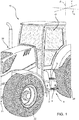
Figure 1 is a partial perspective view of a work vehicle comprising a step ladder according to the present invention; -
Figure 2 is a perspective view in an enlarged scale of the step ladder according to a first embodiment of the present invention; -
Figures 3, 4 and 5 are cross-sectional lateral views along line H-H ofFigure 2 in different respective operative positions; -
Figures 6, 7 and 8 are partial lateral views of the step ladder ofFigures 3, 4 and 5 ; -
Figures 9, 10 and 11 are partial lateral views of the step ladder ofFigures 3, 4 and 5 ; and -
Figures 12 and 13 are partial perspective views of a step ladder according to a second embodiment of the present invention. - With reference to
Figure 1 ,numeral 10 indicates a work vehicle, in particular an agricultural vehicle, such as a tractor or an earth moving machine. -
Work vehicle 10 comprises amain body 20, which preferably defines acab 18 for the user, anundercarriage 21 and traction means 22, for allowing the motion ofmain body 20 andundercarriage 21 on the ground, such as wheels or tracks. - The
work vehicle 10 further comprises astep ladder 1, which is configured to be fixed to a portion ofwork vehicle 10. In the embodiment shown, as shown infigure 1 ,step ladder 1 is arranged in proximity ofcab 18 and fixed to themain body 20 ofwork vehicle 10. -
Step ladder 1 essentially comprises aframe 2 configured to be fixed to the aforementioned portion ofwork vehicle 10 and a plurality ofsteps 3, 4 carried byframe 2. -
Steps 3, 4 are arranged one above the other along a direction Z and extend along a direction Y, which is transversal to direction Z. In the embodiment shown, direction Z is, in use, vertical with respect to the ground and direction Y is perpendicular to direction Z. - In detail,
steps 3, 4 are at least partially staggered along a direction X, which is transversal to directions Z and Y, as shown infigure 2 . - In the described embodiment,
step ladder 1 is fixed to workvehicle 10 in such a manner that direction Y is substantially parallel to a movement direction ofvehicle 10 and exemplarily comprises two steps, namely an upper step 3 and alower step 4. - Upper and
lower steps 3, 4 each comprise atread 6, which is substantially planar and is adapted to be stepped on by a user of thework vehicle 10. In the embodiment shown, upper andlower steps 3, 4 are carried byframe 2 in such a manner thatrespective treads 6 extend perpendicularly to direction Z. - The distance along direction Z between
respective treads 6 of upper andlower steps 3, 4 defines a rise r between upper andlower steps 3, 4, as shown infigure 2 . - It is also possible to define a height h of
step ladder 1, i.e. the total extension ofstep ladder 1 along direction Z, a length L ofstep ladder 1, i.e. the total extension ofstep ladder 1 along direction X, and a mean slope α ofstep ladder 1 as the ratio of height h to length L. - Furthermore,
frame 2 comprises a pair lateral supports, which are spaced from each other along direction Y, and which are configured to carry theaforementioned steps 3, 4. - In particular, the lateral supports are
wings left wing 31 and aright wing 32. In the embodiment shown, left andright wings - Preferably,
frame 2 further comprises amain portion 33, which carries left andright wings right wings main portion 33 along direction Y and are rounded to it. Preferably, left andright wings main portion 33 are formed as a single piece, e.g. in a metallic material.Main portion 33 orwings main body 20 of thework vehicle 10 to fix thestep ladder 1 to the latter. - Advantageously, one or
more steps 3, 4 are movably carried byframe 2, so that they can be slidably adjusted along direction X between a first operative position I and a second operative position II, in order to vary mean slope α between such first and second operative positions I, II. - According to the invention,
step ladder 1 further comprises cam means 5, which support in a movable manner aside 4a of one ormore steps 3, 4 with respect toframe 2, and fixing means 7, which lock aside 4b of said one ormore steps 3, 4 with respect toframe 2 in first or in second operative positions I, II. - In detail,
sides more step 3, 4 along direction Y, namely right and left sides. In further detail, upper andlower steps 3, 4 are arranged between left andright wings left side 4a cooperates withleft wing 31 andright side 4b cooperates withright wing 32. - In the following, according to the exemplarily embodiment and for sake of clarity, upper step 3 is stationary with respect to
frame 2 andlower step 4 is movably carried byframe 2. - In particular, first operative position I corresponds to a retracted position of
lower step 4 with respect to frame 2 (seeFigures 5 ,8 and 11 ) and second operative position II corresponds to an advanced position oflower step 4 with respect to frame 2 (seeFigures 3 ,6 and 9 ). - According to the above,
lower step 4 can assume: - the first operative position I, in which it is completely arranged within left and
right wings Figure 5 ) thereby defining a length L1 ofstep ladder 1 in direction X; and - the second operative position II, in which it is partially arranged within left and
right wings right wings figure 3 ), thereby defining a length L2 ofstep ladder 1 in direction X. - In detail, value L1 is lower than value L2, which is equal to the maximum extension of the
step ladder 1 along direction X (seefigure 3 ). - Preferably,
lower step 4 is further slidably adjustable in a third operative position III, which is interposed between first and second operative positions I, II along direction X (seefigures 4 ,7 and 10 ), thereby defining a length L3 ofstep ladder 1 in direction X. - In detail, value L3 is lower than value L2 but greater than value L1 (see
figure 5 ). Preferably, third operative position III is arranged in the middle between first and second operative positions I, II along direction X. - Therefore, it is possible to define three values α1, α2 and α3 of mean slope α when
lower step 4 is respectively in first, second and third operative positions I, II, III. In detail, value α1 is greater than value α2 and value α2 is greater than value α3. - Furthermore, cam means 5 comprise, in turn, a
guide 8 and a slider 9, which is adapted to slide, in use, inguide 8. - In detail,
guide 8 is formed in one betweenframe 2 andlower step 4 and is directed along direction X. In the embodiment shown,guide 8 is conformed as an opening passing through left wing 31 (seefigure 2 ). - Consequently, slider 9 is carried by the other one between
frame 2 andlower step 4. In detail, slider 9 is integrally connected tolower step 4, in particular atleft side 4a. In further detail, slider 9 is welded tolower step 4. - In the embodiment shown, slider 9 is substantially a pin comprising an attaching
portion 9a, which is fixed toleft side 4a and anengaging portion 9b, which is adapted to engageguide 8 and protrudes from attachingportion 9a along direction Y. In detail, attachingportion 9a and engagingportion 9b are formed as a single piece. -
Step ladder 1 further comprises cam means 12 supporting in a movable mannerright side 4b of lower step 4 (Figures 9 to 11 ). - Cam means 12 comprise, in turn, a
guide 13 and a slider 14, which is adapted to slide in guide 13 (Figures 9 to 11 ). -
Guide 13 is formed in one betweenframe 2 andlower step 4 and slider 14 is carried by the other one betweenframe 2 andlower step 4. - In detail, guide 13 is defined by an
opening 23 extending along direction X and passing throughright wing 32. Slider 14 is conformed as a pin and is integrally connected tolower step 4. In further detail, slider 14 is welded toright side 4b. - In the exemplarily embodiment, slider 14 is a substantially cylindrical pin while slider 9 is a substantially flat pin.
- In particular, opening 23 has a substantially rectangular shape, preferably rounded at its corners, therefore defined by a pair of
end walls upper wall 13c and alower wall 13d, which are opposite to each other along direction Z. -
Opening 23, passing through theright wing 32, allows the insertion of slider 14.End walls front wall 13a and arear wall 13b, define therefore respective abutments for slider 14 along direction X. - In detail, the distance along direction Z between
lower wall 13d andupper wall 13c varies along direction X. In particular,lower wall 13d has a height-variable profile parallel to direction Z. - Advantageously,
lower wall 13d comprises a plurality of protrusions, which determine the height-variable profile oflower wall 13d along direction Z, in addition, the protrusions extend along direction Z and are directed fromlower wall 13d towardsupper wall 13c. In detail, such protrusions are arranged at least at three points oflower wall 13d along direction X. In the described embodiment, the three points oflower wall 13d correspond to the first, second and third operative positions I, II and III oflower step 4. - In detail, slider 14 is adapted to slide between
front wall 13a, which corresponds to first operative position I oflower step 4 andrear wall 13b, which corresponds to second operative position II oflower step 4. - In further detail, when
lower step 4 is in one of first, second and third positions I, II, III, slider 14 simultaneously contactslower wall 13d at one of the protrusions andupper wall 13c (seefigures 9 to 13 ). - Furthermore, fixing means 7 comprise a
coupling element 11 and a pair ofseats first seat 25 and asecond seat 26, which are realized in one betweenlower step 4 andframe 2. Preferably, first andsecond seats coupling element 11 is configured to selectively engage one of first andsecond seats lower step 4 with respect toframe 2 in first and second operative positions I, II, respectively. - With reference to the first embodiment depicted in
figures 1 to 5 ,coupling element 11 is threaded element. In detail, first andsecond seats coupling element 11. - Alternatively, as shown in a second embodiment depicted in
figures 12 and 13 ,coupling element 11 is a pin that can be fixed toright wing 32 via alynchpin connection 28. In the described embodiment,such lynching connection 28 comprises adowel 29 configured to be inserted in a through hole realized in thecoupling element 11 and that can be maintained in such coupled position byelastic means 30. For sake of brevity, such embodiments will not further be described in detail. - According to a not-shown alternative embodiment,
coupling element 11 is carried by one betweenlower step 4 andframe 2 and first andsecond seats lower step 4 andframe 2. - Fixing means 7 further comprise a
third seat 27, which is interposed between first andsecond seats coupling element 11 is configured to selectively engagethird seat 27 to lock, in use,lower step 4 in third operative position III (Figures 4 ,10 ,12 and 13 ) . - In the described embodiment,
third seat 27 is arranged in the middle between first andsecond seats third seat 27 is arranged at a higher position with respect to first andsecond seats -
Step ladder 1 further comprises amovable connection assembly 19 to movably coupleright side 4b withframe 2. Preferably, suchmovable connection assembly 19 comprises a connectingrod 15. - Connecting
rod 15 comprises afirst end 15a, which is hinged toframe 2 by means of afirst hinge 40 and asecond end 15b, which is hinged to slider 14 by means of a second hinge 41. First andsecond ends Figures 9 to 11 ). - In particular, fixing means 7 are adapted to lock the position of
movable connection assembly 19 with respect toframe 2. - According to the above, fixing means 7 are adapted to lock connecting
rod 15 at an intermediate portion between first andsecond ends rod 15 comprises ahole 16, which is formed at an intermediate portion between first andsecond ends figures 9 to 12 ). In further detail,coupling element 11 is adapted to simultaneously engagehole 16 and one of first, second orthird seats lower step 4 in one of first, second or third operative positions I, II, III, respectively. - In addition, connecting
rod 15 is also slidable with respect to first hinge 40 (Figures 3 to 5 ). In detail, connectingrod 15 comprises aslot 17, which is adapted to be slidably engaged byfirst hinge 40. - As shown in
figures 3 to 5 , the position ofhole 16 along direction Z is variable, as a consequence of the rotation of connectingrod 15 with respect tofirst hinge 40. In detail, the position ofhole 16 along direction Z whenstep ladder 4 is in third operative positions III is different, in particular higher, from the position ofhole 16 whenstep ladder 4 is in first or in second operative positions I, II. - In particular, as described above,
third seat 27 is arranged at a higher position with respect to first andsecond seats step ladder 4 is in third operative position III,third seat 27 is aligned withhole 16 and boththird seat 27 andhole 16 are simultaneously engageable by couplingelement 11. - The operation of the
step ladder 1 according to the invention and described as above is the following. In particular, the operation will be described starting from a condition in whichlower step 4 is locked in first operative position I. In this condition, length L is equal to value L1 and mean slope α is equal to value α1 (Figure 5 ). - In order to set
lower step 4 in second or in third operative positions II, III,coupling element 11 is disengaged fromfirst seat 25 andlower step 4 is subsequently slid parallel to direction X. Preferably,coupling element 11 is disengaged fromfirst seat 25, while remaining at least partially engaged withhole 16. - While
lower step 4 is moved, slider 9 slides inguide 8 and slider 14 slides inguide 13. In detail, slider 14 moves fromrear wall 13b towardsfront wall 13a. - In addition, connecting
rod 15 rotates with respect to first and second hinges 40, 41 and slides with respect tofirst hinge 40. In detail,slot 17 slides with respect tofirst hinge 40. - Once
lower step 4 reaches second or third operative positions II, III,lower step 4 is subsequently locked with respect toframe 2 by fixingmeans 7. In detail,coupling element 11 engages second orthird seats hole 16. As a consequence, connectingrod 15 is also locked with respect toframe 2. - In detail, when
lower step 4 is set in second operative position II, length L is equal to value L2 and mean slope α is equal to value α2. Whenlower step 4 is set in third operative position III, length L is equal to value L3 and mean slope α is equal to value α3. - The above operation is a manual operation of the
step ladder 1. Clearly, it can be foreseen to providestep ladder 1 with automatic actuation means for automatically slidably movinglower step 4 with respect toframe 2 and automatically engaging or disengaging fixing means 7. - In view of the foregoing, the advantages of
step ladder 1 according to the invention are apparent. - In particular, since
lower step 4 is movably carried byframe 2 so that it can be slidably adjustable along direction X between first and second operative positions I, II, length L and mean slope α ofstep ladder 1 can be easily varied depending on the user's needs. - Accordingly,
step ladder 1 can be comfortably used, while complying with the homologation requirements ofwork vehicle 1. - In fact, when
lower step 4 is in first operative position I, the encumbrance ofwork vehicle 1 parallel to direction X is minimized so as to meet the homologation requirements and mean slope α is equal to its maximum value, i.e. α1. - On the contrary, when
lower step 4 is in second operative position II, the encumbrance ofwork vehicle 1 parallel to direction X is maximized and mean slope α is equal to its minimum value, i.e. α2, and the user's comfort is maximized. - Furthermore, since cam means 5 support in a movable manner
left side 4a with respect toframe 2 and fixing means 7 lockright side 4b with respect toframe 2, it is possible to adjust the position oflower step 4 without completely removing it fromframe 2. - In case of automatic sliding of
lower step 4 and engaging/disengaging of the fixing means 7, the passage between the different operative positions I, II, III oflower step 4 can be realized in a totally automatic way without any intervention of the user. - It is clear that modifications can be made to the described
step ladder 1 which do not extend beyond the scope of protection defined by the claims. - In particular,
lower step 4 could be continuously slidably adjustable in a plurality of positions between first and second operative positions I, II along direction X. In other words, third operative position III may correspond to any one of the plurality of other positions between first and second operative positions I, II along direction X.
Claims (15)
- Step ladder (1) for a work vehicle (10), comprising a frame (2) configured to be fixed to a portion of said work vehicle (10) and a plurality of steps (3; 4) carried by said frame (2);
said plurality of steps (3; 4) being arranged one above the other along a first direction (Z) and extending along a second direction (Y) transversal to said first direction (Z);
wherein at least one (4) among said steps (3; 4) is movably carried by said frame (2) so that it can be slidably adjustable along a third direction (X) between at least a first and a second operative positions (I, II); said third direction (X) being transversal to said first and second directions (Z, Y);
said step ladder (1) further comprising first cam means (5) and fixing means (7), said first cam means (5) supporting in a movable manner a first side (4a; 4b) of said at least one step (4) with respect to said frame (2) and said fixing means (7) locking a second side (4b; 4a) of said at least one step (4) with respect to said frame (2) in said at least first and second operative positions (I, II). - Step ladder according to claim 1, wherein said first cam means (5) comprise at least one first guide (8) and at least one first slider (9), which is adapted to slide, in use, in said at least one first guide (8);
said at least one first guide (8) being formed in one between said frame (2) and said at least one step (4); said at least one first slider (9) being carried by the other one between said frame (2) and said at least one step (4). - Step ladder according to claim 2, wherein said at least one first guide (8) extends along said third direction (X).
- Step ladder according to any one of the foregoing claims, wherein said first and second sides (4a, 4b; 4b, 4a) are opposite sides of said at least one step (4) along said second direction (Y).
- Step ladder according to any one of the foregoing claims, wherein said frame (2) comprises at least a first support element (31) and a second support element (32), which are spaced from each other along said second direction (Y);
said plurality of steps (3; 4) being arranged between said first and second support elements (31, 32) along said second direction (Y) so that said first side (4a; 4b) cooperates, in use, with said first support element (31) and said second side (4b; 4a) cooperates, in use, with said second support element (32). - Step ladder according to any one of the foregoing claims, wherein said fixing means (7) comprise a coupling element (11) and at least two seats (25, 26) realized in one between said at least one step (4) and said frame (2) along said third direction (X), said coupling element (11) being configured to selectively engage one of said seats (25, 26) to lock, in use, the position of said at least one step (4) with respect to said frame (2).
- Step ladder according to claim 6, wherein said fixing means (7) comprise a further seat (27), which is interposed between said at least two seats (25, 26) along said third direction (X); said coupling element (11) being configured to selectively engage said further seat (27) to lock, in use, the position of said at least one step (4) in a third operative position (III) with respect to said frame (2).
- Step ladder according to any one of the foregoing claims, comprising second cam means (12) supporting in a movable manner said second side (4b; 4a).
- Step ladder according to claim 8, wherein said second cam means (12) comprise at least one second guide (13) and at least one second slider (14), which is adapted to slide in said at least one second guide (13);
said at least one second guide (13) being formed in one between said frame (2) and said at least one step (4); said at least one second slider (14) being carried by the other one between said frame (2) and said at least one step (4). - Step ladder according to claim 9, wherein said at least one second guide (13) is delimited along said first direction (Z) by a first wall (13c) and a second wall (13d), which are opposite to each other;
one (13d) between said first and second walls (13c, 13d) having a profile variable along said first direction (Z), so that a distance between said first and second walls (13c, 13d) along said first direction (Z) is variable along said third direction (X). - Step ladder according to any one of the foregoing claims, further comprising a movable connection assembly (19) adapted to movably couple said second side (4b; 4a) with said frame (2);
said fixing means (7) being adapted to lock the position of said movable connection assembly (19) with respect to said frame (2). - Step ladder according to claim 11, when depending on any one of claims 9 or 10, wherein said movable connection assembly (19) comprises a connecting rod (15);
said connecting rod (15) comprising a first end (15a), which is hinged to said frame (2) by means of a first hinge (40) and a second end (15b), which is hinged to said at least one second slider (14) by means of a second hinge (41);
said fixing means (7) locking said connecting rod (15) at an intermediate portion between said first end (15a) and said second end (15b). - Step ladder according to any one of claims 7 to 12, wherein said coupling element (11) comprises a pin fixable via a lynchpin (28) in one of said two seats (25, 26) or said further seat (27).
- Step ladder according to any one of claims 7 to 12, wherein said coupling element (11) comprises a pin provided with a thread configured to cooperate with a respective thread realized in said two seats (25, 26) and said further seat (27) .
- A work vehicle (10) comprising:- a main body (20);- an undercarriage (21)- traction means (22), for allowing the motion of said main body (20) and said undercarriage (21) on the ground; and- a step ladder (1) according to any one of the foregoing claims configured to be fixed to a portion of said work vehicle (10) .
Applications Claiming Priority (1)
| Application Number | Priority Date | Filing Date | Title |
|---|---|---|---|
| IT102020000014665A IT202000014665A1 (en) | 2020-06-18 | 2020-06-18 | IMPROVED WORK VEHICLE LADDER |
Publications (2)
| Publication Number | Publication Date |
|---|---|
| EP3925829A1 true EP3925829A1 (en) | 2021-12-22 |
| EP3925829B1 EP3925829B1 (en) | 2025-08-06 |
Family
ID=72179105
Family Applications (1)
| Application Number | Title | Priority Date | Filing Date |
|---|---|---|---|
| EP21180214.5A Active EP3925829B1 (en) | 2020-06-18 | 2021-06-18 | Improved step ladder for a work vehicle |
Country Status (2)
| Country | Link |
|---|---|
| EP (1) | EP3925829B1 (en) |
| IT (1) | IT202000014665A1 (en) |
Citations (6)
| Publication number | Priority date | Publication date | Assignee | Title |
|---|---|---|---|---|
| GB1333291A (en) * | 1971-01-06 | 1973-10-10 | Standard Telephones Cables Ltd | Step ladders |
| FR2247079A5 (en) * | 1973-10-03 | 1975-05-02 | Quaghebeur Nicole | Caravan removable footstep - is folding type and adjustable to fit different types of chassis |
| US4185849A (en) * | 1978-02-03 | 1980-01-29 | Jaeger Wilbert J | Retractable step for motor vehicle |
| US6655706B1 (en) * | 2001-10-26 | 2003-12-02 | Hickory Springs Manufacturing Company | Extendable-retractable RV step and method of assembling same |
| DE202014104298U1 (en) * | 2014-09-11 | 2014-10-06 | Rücker GmbH | Vehicle stairlift |
| DE202017002528U1 (en) * | 2017-05-12 | 2017-10-10 | Caterpillar Inc. | Construction machine with a Auftiegsmittel |
-
2020
- 2020-06-18 IT IT102020000014665A patent/IT202000014665A1/en unknown
-
2021
- 2021-06-18 EP EP21180214.5A patent/EP3925829B1/en active Active
Patent Citations (6)
| Publication number | Priority date | Publication date | Assignee | Title |
|---|---|---|---|---|
| GB1333291A (en) * | 1971-01-06 | 1973-10-10 | Standard Telephones Cables Ltd | Step ladders |
| FR2247079A5 (en) * | 1973-10-03 | 1975-05-02 | Quaghebeur Nicole | Caravan removable footstep - is folding type and adjustable to fit different types of chassis |
| US4185849A (en) * | 1978-02-03 | 1980-01-29 | Jaeger Wilbert J | Retractable step for motor vehicle |
| US6655706B1 (en) * | 2001-10-26 | 2003-12-02 | Hickory Springs Manufacturing Company | Extendable-retractable RV step and method of assembling same |
| DE202014104298U1 (en) * | 2014-09-11 | 2014-10-06 | Rücker GmbH | Vehicle stairlift |
| DE202017002528U1 (en) * | 2017-05-12 | 2017-10-10 | Caterpillar Inc. | Construction machine with a Auftiegsmittel |
Also Published As
| Publication number | Publication date |
|---|---|
| EP3925829B1 (en) | 2025-08-06 |
| IT202000014665A1 (en) | 2021-12-18 |
Similar Documents
| Publication | Publication Date | Title |
|---|---|---|
| US9380760B2 (en) | Folding pet ramp and steps device with telescoping handle | |
| US9149116B2 (en) | Drawer structure | |
| CA2384867C (en) | Sliding device for a fifth wheel | |
| US20060289581A1 (en) | Trunk-specific functional arrangement for a motor vehicle | |
| DE102008002822A1 (en) | Child safety seat for positioning on and fixing at vehicle seats in motor vehicles, has height-adjustable headrest and two protective flanges, where positive guide ensures parallel shift over total height adjusting area | |
| US10646040B2 (en) | Supporting assembly for rack system | |
| EP1419057B1 (en) | Sliding sun visor | |
| EP3925829B1 (en) | Improved step ladder for a work vehicle | |
| DE102012205485B4 (en) | Unlocking device for a vehicle seat with entry-facilitating functionality and method for operating an unlocking device | |
| DE102010063819A1 (en) | Motor car i.e. passenger car, has sliding rail fastened in rear portion of luggage compartment on loading floor, where floor plate, rail and other rail exhibit depth extension of certain range of depth extension of luggage compartment | |
| DE69802181T2 (en) | ARRANGEMENT FOR LONG ADJUSTMENT AND LOCKING OF A MOTOR VEHICLE SEAT IN REGULATED POSITION | |
| US7753424B2 (en) | Armrest arrangement for a motor vehicle door | |
| CA2989592A1 (en) | Stowable step for vehicle access | |
| CN110949567A (en) | AGV Chassis | |
| CA2717122C (en) | Sliding hitch assembly | |
| US20030168567A1 (en) | Locking device for a vehicle seat | |
| US20070102949A1 (en) | Toolbox rollback kit for pickup trucks | |
| EP1661752B1 (en) | Vehicle seat device | |
| DE102004007176C5 (en) | Rail for a motor vehicle seat | |
| US20210362659A1 (en) | Adaptor for mounting a cargo carrier to a vehicle | |
| DE102011114621B4 (en) | Vehicle cargo space with a height-adjustable loading floor | |
| DE102007030045A1 (en) | Armrest arrangement for a motor vehicle door has an armrest that is driven along the adjustment direction with the adjusting movement of the slide along the guide rails | |
| KR102111675B1 (en) | Seat sliding apparatus for vehicle | |
| EP1500576A2 (en) | Roof arrangement for large capacity transport vehicle | |
| US12202395B1 (en) | Folding convertible ramp body for use with vehicles, a combination vehicle and folding convertible ramp body, and/or a device for loading rolling tools into a vehicle using a folding convertible ramp body |
Legal Events
| Date | Code | Title | Description |
|---|---|---|---|
| PUAI | Public reference made under article 153(3) epc to a published international application that has entered the european phase |
Free format text: ORIGINAL CODE: 0009012 |
|
| STAA | Information on the status of an ep patent application or granted ep patent |
Free format text: STATUS: THE APPLICATION HAS BEEN PUBLISHED |
|
| AK | Designated contracting states |
Kind code of ref document: A1 Designated state(s): AL AT BE BG CH CY CZ DE DK EE ES FI FR GB GR HR HU IE IS IT LI LT LU LV MC MK MT NL NO PL PT RO RS SE SI SK SM TR |
|
| B565 | Issuance of search results under rule 164(2) epc |
Effective date: 20211110 |
|
| STAA | Information on the status of an ep patent application or granted ep patent |
Free format text: STATUS: REQUEST FOR EXAMINATION WAS MADE |
|
| 17P | Request for examination filed |
Effective date: 20220622 |
|
| RBV | Designated contracting states (corrected) |
Designated state(s): AL AT BE BG CH CY CZ DE DK EE ES FI FR GB GR HR HU IE IS IT LI LT LU LV MC MK MT NL NO PL PT RO RS SE SI SK SM TR |
|
| RAP3 | Party data changed (applicant data changed or rights of an application transferred) |
Owner name: CNH INDUSTRIAL ITALIA S.P.A. |
|
| GRAP | Despatch of communication of intention to grant a patent |
Free format text: ORIGINAL CODE: EPIDOSNIGR1 |
|
| STAA | Information on the status of an ep patent application or granted ep patent |
Free format text: STATUS: GRANT OF PATENT IS INTENDED |
|
| INTG | Intention to grant announced |
Effective date: 20250128 |
|
| GRAS | Grant fee paid |
Free format text: ORIGINAL CODE: EPIDOSNIGR3 |
|
| GRAA | (expected) grant |
Free format text: ORIGINAL CODE: 0009210 |
|
| STAA | Information on the status of an ep patent application or granted ep patent |
Free format text: STATUS: THE PATENT HAS BEEN GRANTED |
|
| AK | Designated contracting states |
Kind code of ref document: B1 Designated state(s): AL AT BE BG CH CY CZ DE DK EE ES FI FR GB GR HR HU IE IS IT LI LT LU LV MC MK MT NL NO PL PT RO RS SE SI SK SM TR |
|
| REG | Reference to a national code |
Ref country code: GB Ref legal event code: FG4D |
|
| REG | Reference to a national code |
Ref country code: CH Ref legal event code: EP |
|
| REG | Reference to a national code |
Ref country code: DE Ref legal event code: R096 Ref document number: 602021035452 Country of ref document: DE |
|
| REG | Reference to a national code |
Ref country code: IE Ref legal event code: FG4D |
|
| REG | Reference to a national code |
Ref country code: NL Ref legal event code: MP Effective date: 20250806 |
|
| PG25 | Lapsed in a contracting state [announced via postgrant information from national office to epo] |
Ref country code: IS Free format text: LAPSE BECAUSE OF FAILURE TO SUBMIT A TRANSLATION OF THE DESCRIPTION OR TO PAY THE FEE WITHIN THE PRESCRIBED TIME-LIMIT Effective date: 20251206 |
|
| PG25 | Lapsed in a contracting state [announced via postgrant information from national office to epo] |
Ref country code: NO Free format text: LAPSE BECAUSE OF FAILURE TO SUBMIT A TRANSLATION OF THE DESCRIPTION OR TO PAY THE FEE WITHIN THE PRESCRIBED TIME-LIMIT Effective date: 20251106 |
|
| REG | Reference to a national code |
Ref country code: LT Ref legal event code: MG9D |
|
| PG25 | Lapsed in a contracting state [announced via postgrant information from national office to epo] |
Ref country code: PT Free format text: LAPSE BECAUSE OF FAILURE TO SUBMIT A TRANSLATION OF THE DESCRIPTION OR TO PAY THE FEE WITHIN THE PRESCRIBED TIME-LIMIT Effective date: 20251209 |
|
| PG25 | Lapsed in a contracting state [announced via postgrant information from national office to epo] |
Ref country code: FI Free format text: LAPSE BECAUSE OF FAILURE TO SUBMIT A TRANSLATION OF THE DESCRIPTION OR TO PAY THE FEE WITHIN THE PRESCRIBED TIME-LIMIT Effective date: 20250806 |
|
| PG25 | Lapsed in a contracting state [announced via postgrant information from national office to epo] |
Ref country code: HR Free format text: LAPSE BECAUSE OF FAILURE TO SUBMIT A TRANSLATION OF THE DESCRIPTION OR TO PAY THE FEE WITHIN THE PRESCRIBED TIME-LIMIT Effective date: 20250806 Ref country code: NL Free format text: LAPSE BECAUSE OF FAILURE TO SUBMIT A TRANSLATION OF THE DESCRIPTION OR TO PAY THE FEE WITHIN THE PRESCRIBED TIME-LIMIT Effective date: 20250806 |
|
| PG25 | Lapsed in a contracting state [announced via postgrant information from national office to epo] |
Ref country code: GR Free format text: LAPSE BECAUSE OF FAILURE TO SUBMIT A TRANSLATION OF THE DESCRIPTION OR TO PAY THE FEE WITHIN THE PRESCRIBED TIME-LIMIT Effective date: 20251107 |
|
| PG25 | Lapsed in a contracting state [announced via postgrant information from national office to epo] |
Ref country code: SE Free format text: LAPSE BECAUSE OF FAILURE TO SUBMIT A TRANSLATION OF THE DESCRIPTION OR TO PAY THE FEE WITHIN THE PRESCRIBED TIME-LIMIT Effective date: 20250806 |
|
| PG25 | Lapsed in a contracting state [announced via postgrant information from national office to epo] |
Ref country code: LV Free format text: LAPSE BECAUSE OF FAILURE TO SUBMIT A TRANSLATION OF THE DESCRIPTION OR TO PAY THE FEE WITHIN THE PRESCRIBED TIME-LIMIT Effective date: 20250806 |
|
| PG25 | Lapsed in a contracting state [announced via postgrant information from national office to epo] |
Ref country code: PL Free format text: LAPSE BECAUSE OF FAILURE TO SUBMIT A TRANSLATION OF THE DESCRIPTION OR TO PAY THE FEE WITHIN THE PRESCRIBED TIME-LIMIT Effective date: 20250806 Ref country code: BG Free format text: LAPSE BECAUSE OF FAILURE TO SUBMIT A TRANSLATION OF THE DESCRIPTION OR TO PAY THE FEE WITHIN THE PRESCRIBED TIME-LIMIT Effective date: 20250806 |
|
| PG25 | Lapsed in a contracting state [announced via postgrant information from national office to epo] |
Ref country code: RS Free format text: LAPSE BECAUSE OF FAILURE TO SUBMIT A TRANSLATION OF THE DESCRIPTION OR TO PAY THE FEE WITHIN THE PRESCRIBED TIME-LIMIT Effective date: 20251106 |
|
| PG25 | Lapsed in a contracting state [announced via postgrant information from national office to epo] |
Ref country code: ES Free format text: LAPSE BECAUSE OF FAILURE TO SUBMIT A TRANSLATION OF THE DESCRIPTION OR TO PAY THE FEE WITHIN THE PRESCRIBED TIME-LIMIT Effective date: 20250806 |
|
| REG | Reference to a national code |
Ref country code: AT Ref legal event code: MK05 Ref document number: 1821481 Country of ref document: AT Kind code of ref document: T Effective date: 20250806 |
|
| PG25 | Lapsed in a contracting state [announced via postgrant information from national office to epo] |
Ref country code: SM Free format text: LAPSE BECAUSE OF FAILURE TO SUBMIT A TRANSLATION OF THE DESCRIPTION OR TO PAY THE FEE WITHIN THE PRESCRIBED TIME-LIMIT Effective date: 20250806 |
|
| PG25 | Lapsed in a contracting state [announced via postgrant information from national office to epo] |
Ref country code: DK Free format text: LAPSE BECAUSE OF FAILURE TO SUBMIT A TRANSLATION OF THE DESCRIPTION OR TO PAY THE FEE WITHIN THE PRESCRIBED TIME-LIMIT Effective date: 20250806 |
|
| PG25 | Lapsed in a contracting state [announced via postgrant information from national office to epo] |
Ref country code: AT Free format text: LAPSE BECAUSE OF FAILURE TO SUBMIT A TRANSLATION OF THE DESCRIPTION OR TO PAY THE FEE WITHIN THE PRESCRIBED TIME-LIMIT Effective date: 20250806 |
|
| PG25 | Lapsed in a contracting state [announced via postgrant information from national office to epo] |
Ref country code: CZ Free format text: LAPSE BECAUSE OF FAILURE TO SUBMIT A TRANSLATION OF THE DESCRIPTION OR TO PAY THE FEE WITHIN THE PRESCRIBED TIME-LIMIT Effective date: 20250806 |
|
| PG25 | Lapsed in a contracting state [announced via postgrant information from national office to epo] |
Ref country code: EE Free format text: LAPSE BECAUSE OF FAILURE TO SUBMIT A TRANSLATION OF THE DESCRIPTION OR TO PAY THE FEE WITHIN THE PRESCRIBED TIME-LIMIT Effective date: 20250806 Ref country code: SK Free format text: LAPSE BECAUSE OF FAILURE TO SUBMIT A TRANSLATION OF THE DESCRIPTION OR TO PAY THE FEE WITHIN THE PRESCRIBED TIME-LIMIT Effective date: 20250806 |