EP3925816A1 - Vehicle drive system with a removable battery - Google Patents
Vehicle drive system with a removable battery Download PDFInfo
- Publication number
- EP3925816A1 EP3925816A1 EP21178222.2A EP21178222A EP3925816A1 EP 3925816 A1 EP3925816 A1 EP 3925816A1 EP 21178222 A EP21178222 A EP 21178222A EP 3925816 A1 EP3925816 A1 EP 3925816A1
- Authority
- EP
- European Patent Office
- Prior art keywords
- battery
- inverter
- motor
- batteries
- batt1
- Prior art date
- Legal status (The legal status is an assumption and is not a legal conclusion. Google has not performed a legal analysis and makes no representation as to the accuracy of the status listed.)
- Granted
Links
Images


Classifications
-
- B—PERFORMING OPERATIONS; TRANSPORTING
- B60—VEHICLES IN GENERAL
- B60L—PROPULSION OF ELECTRICALLY-PROPELLED VEHICLES; SUPPLYING ELECTRIC POWER FOR AUXILIARY EQUIPMENT OF ELECTRICALLY-PROPELLED VEHICLES; ELECTRODYNAMIC BRAKE SYSTEMS FOR VEHICLES IN GENERAL; MAGNETIC SUSPENSION OR LEVITATION FOR VEHICLES; MONITORING OPERATING VARIABLES OF ELECTRICALLY-PROPELLED VEHICLES; ELECTRIC SAFETY DEVICES FOR ELECTRICALLY-PROPELLED VEHICLES
- B60L50/00—Electric propulsion with power supplied within the vehicle
- B60L50/50—Electric propulsion with power supplied within the vehicle using propulsion power supplied by batteries or fuel cells
- B60L50/60—Electric propulsion with power supplied within the vehicle using propulsion power supplied by batteries or fuel cells using power supplied by batteries
-
- B—PERFORMING OPERATIONS; TRANSPORTING
- B60—VEHICLES IN GENERAL
- B60K—ARRANGEMENT OR MOUNTING OF PROPULSION UNITS OR OF TRANSMISSIONS IN VEHICLES; ARRANGEMENT OR MOUNTING OF PLURAL DIVERSE PRIME-MOVERS IN VEHICLES; AUXILIARY DRIVES FOR VEHICLES; INSTRUMENTATION OR DASHBOARDS FOR VEHICLES; ARRANGEMENTS IN CONNECTION WITH COOLING, AIR INTAKE, GAS EXHAUST OR FUEL SUPPLY OF PROPULSION UNITS IN VEHICLES
- B60K6/00—Arrangement or mounting of plural diverse prime-movers for mutual or common propulsion, e.g. hybrid propulsion systems comprising electric motors and internal combustion engines
- B60K6/20—Arrangement or mounting of plural diverse prime-movers for mutual or common propulsion, e.g. hybrid propulsion systems comprising electric motors and internal combustion engines the prime-movers consisting of electric motors and internal combustion engines, e.g. HEVs
- B60K6/22—Arrangement or mounting of plural diverse prime-movers for mutual or common propulsion, e.g. hybrid propulsion systems comprising electric motors and internal combustion engines the prime-movers consisting of electric motors and internal combustion engines, e.g. HEVs characterised by apparatus, components or means specially adapted for HEVs
- B60K6/28—Arrangement or mounting of plural diverse prime-movers for mutual or common propulsion, e.g. hybrid propulsion systems comprising electric motors and internal combustion engines the prime-movers consisting of electric motors and internal combustion engines, e.g. HEVs characterised by apparatus, components or means specially adapted for HEVs characterised by the electric energy storing means, e.g. batteries or capacitors
-
- B—PERFORMING OPERATIONS; TRANSPORTING
- B60—VEHICLES IN GENERAL
- B60L—PROPULSION OF ELECTRICALLY-PROPELLED VEHICLES; SUPPLYING ELECTRIC POWER FOR AUXILIARY EQUIPMENT OF ELECTRICALLY-PROPELLED VEHICLES; ELECTRODYNAMIC BRAKE SYSTEMS FOR VEHICLES IN GENERAL; MAGNETIC SUSPENSION OR LEVITATION FOR VEHICLES; MONITORING OPERATING VARIABLES OF ELECTRICALLY-PROPELLED VEHICLES; ELECTRIC SAFETY DEVICES FOR ELECTRICALLY-PROPELLED VEHICLES
- B60L58/00—Methods or circuit arrangements for monitoring or controlling batteries or fuel cells, specially adapted for electric vehicles
- B60L58/10—Methods or circuit arrangements for monitoring or controlling batteries or fuel cells, specially adapted for electric vehicles for monitoring or controlling batteries
-
- B—PERFORMING OPERATIONS; TRANSPORTING
- B60—VEHICLES IN GENERAL
- B60K—ARRANGEMENT OR MOUNTING OF PROPULSION UNITS OR OF TRANSMISSIONS IN VEHICLES; ARRANGEMENT OR MOUNTING OF PLURAL DIVERSE PRIME-MOVERS IN VEHICLES; AUXILIARY DRIVES FOR VEHICLES; INSTRUMENTATION OR DASHBOARDS FOR VEHICLES; ARRANGEMENTS IN CONNECTION WITH COOLING, AIR INTAKE, GAS EXHAUST OR FUEL SUPPLY OF PROPULSION UNITS IN VEHICLES
- B60K1/00—Arrangement or mounting of electrical propulsion units
- B60K1/04—Arrangement or mounting of electrical propulsion units of the electric storage means for propulsion
-
- B—PERFORMING OPERATIONS; TRANSPORTING
- B60—VEHICLES IN GENERAL
- B60K—ARRANGEMENT OR MOUNTING OF PROPULSION UNITS OR OF TRANSMISSIONS IN VEHICLES; ARRANGEMENT OR MOUNTING OF PLURAL DIVERSE PRIME-MOVERS IN VEHICLES; AUXILIARY DRIVES FOR VEHICLES; INSTRUMENTATION OR DASHBOARDS FOR VEHICLES; ARRANGEMENTS IN CONNECTION WITH COOLING, AIR INTAKE, GAS EXHAUST OR FUEL SUPPLY OF PROPULSION UNITS IN VEHICLES
- B60K6/00—Arrangement or mounting of plural diverse prime-movers for mutual or common propulsion, e.g. hybrid propulsion systems comprising electric motors and internal combustion engines
- B60K6/20—Arrangement or mounting of plural diverse prime-movers for mutual or common propulsion, e.g. hybrid propulsion systems comprising electric motors and internal combustion engines the prime-movers consisting of electric motors and internal combustion engines, e.g. HEVs
- B60K6/22—Arrangement or mounting of plural diverse prime-movers for mutual or common propulsion, e.g. hybrid propulsion systems comprising electric motors and internal combustion engines the prime-movers consisting of electric motors and internal combustion engines, e.g. HEVs characterised by apparatus, components or means specially adapted for HEVs
- B60K6/24—Arrangement or mounting of plural diverse prime-movers for mutual or common propulsion, e.g. hybrid propulsion systems comprising electric motors and internal combustion engines the prime-movers consisting of electric motors and internal combustion engines, e.g. HEVs characterised by apparatus, components or means specially adapted for HEVs characterised by the combustion engines
-
- B—PERFORMING OPERATIONS; TRANSPORTING
- B60—VEHICLES IN GENERAL
- B60K—ARRANGEMENT OR MOUNTING OF PROPULSION UNITS OR OF TRANSMISSIONS IN VEHICLES; ARRANGEMENT OR MOUNTING OF PLURAL DIVERSE PRIME-MOVERS IN VEHICLES; AUXILIARY DRIVES FOR VEHICLES; INSTRUMENTATION OR DASHBOARDS FOR VEHICLES; ARRANGEMENTS IN CONNECTION WITH COOLING, AIR INTAKE, GAS EXHAUST OR FUEL SUPPLY OF PROPULSION UNITS IN VEHICLES
- B60K6/00—Arrangement or mounting of plural diverse prime-movers for mutual or common propulsion, e.g. hybrid propulsion systems comprising electric motors and internal combustion engines
- B60K6/20—Arrangement or mounting of plural diverse prime-movers for mutual or common propulsion, e.g. hybrid propulsion systems comprising electric motors and internal combustion engines the prime-movers consisting of electric motors and internal combustion engines, e.g. HEVs
- B60K6/22—Arrangement or mounting of plural diverse prime-movers for mutual or common propulsion, e.g. hybrid propulsion systems comprising electric motors and internal combustion engines the prime-movers consisting of electric motors and internal combustion engines, e.g. HEVs characterised by apparatus, components or means specially adapted for HEVs
- B60K6/26—Arrangement or mounting of plural diverse prime-movers for mutual or common propulsion, e.g. hybrid propulsion systems comprising electric motors and internal combustion engines the prime-movers consisting of electric motors and internal combustion engines, e.g. HEVs characterised by apparatus, components or means specially adapted for HEVs characterised by the motors or the generators
-
- B—PERFORMING OPERATIONS; TRANSPORTING
- B60—VEHICLES IN GENERAL
- B60K—ARRANGEMENT OR MOUNTING OF PROPULSION UNITS OR OF TRANSMISSIONS IN VEHICLES; ARRANGEMENT OR MOUNTING OF PLURAL DIVERSE PRIME-MOVERS IN VEHICLES; AUXILIARY DRIVES FOR VEHICLES; INSTRUMENTATION OR DASHBOARDS FOR VEHICLES; ARRANGEMENTS IN CONNECTION WITH COOLING, AIR INTAKE, GAS EXHAUST OR FUEL SUPPLY OF PROPULSION UNITS IN VEHICLES
- B60K6/00—Arrangement or mounting of plural diverse prime-movers for mutual or common propulsion, e.g. hybrid propulsion systems comprising electric motors and internal combustion engines
- B60K6/20—Arrangement or mounting of plural diverse prime-movers for mutual or common propulsion, e.g. hybrid propulsion systems comprising electric motors and internal combustion engines the prime-movers consisting of electric motors and internal combustion engines, e.g. HEVs
- B60K6/42—Arrangement or mounting of plural diverse prime-movers for mutual or common propulsion, e.g. hybrid propulsion systems comprising electric motors and internal combustion engines the prime-movers consisting of electric motors and internal combustion engines, e.g. HEVs characterised by the architecture of the hybrid electric vehicle
- B60K6/44—Series-parallel type
-
- B—PERFORMING OPERATIONS; TRANSPORTING
- B60—VEHICLES IN GENERAL
- B60K—ARRANGEMENT OR MOUNTING OF PROPULSION UNITS OR OF TRANSMISSIONS IN VEHICLES; ARRANGEMENT OR MOUNTING OF PLURAL DIVERSE PRIME-MOVERS IN VEHICLES; AUXILIARY DRIVES FOR VEHICLES; INSTRUMENTATION OR DASHBOARDS FOR VEHICLES; ARRANGEMENTS IN CONNECTION WITH COOLING, AIR INTAKE, GAS EXHAUST OR FUEL SUPPLY OF PROPULSION UNITS IN VEHICLES
- B60K7/00—Disposition of motor in, or adjacent to, traction wheel
- B60K7/0007—Disposition of motor in, or adjacent to, traction wheel the motor being electric
-
- B—PERFORMING OPERATIONS; TRANSPORTING
- B60—VEHICLES IN GENERAL
- B60L—PROPULSION OF ELECTRICALLY-PROPELLED VEHICLES; SUPPLYING ELECTRIC POWER FOR AUXILIARY EQUIPMENT OF ELECTRICALLY-PROPELLED VEHICLES; ELECTRODYNAMIC BRAKE SYSTEMS FOR VEHICLES IN GENERAL; MAGNETIC SUSPENSION OR LEVITATION FOR VEHICLES; MONITORING OPERATING VARIABLES OF ELECTRICALLY-PROPELLED VEHICLES; ELECTRIC SAFETY DEVICES FOR ELECTRICALLY-PROPELLED VEHICLES
- B60L15/00—Methods, circuits, or devices for controlling the traction-motor speed of electrically-propelled vehicles
- B60L15/20—Methods, circuits, or devices for controlling the traction-motor speed of electrically-propelled vehicles for control of the vehicle or its driving motor to achieve a desired performance, e.g. speed, torque, programmed variation of speed
-
- B—PERFORMING OPERATIONS; TRANSPORTING
- B60—VEHICLES IN GENERAL
- B60L—PROPULSION OF ELECTRICALLY-PROPELLED VEHICLES; SUPPLYING ELECTRIC POWER FOR AUXILIARY EQUIPMENT OF ELECTRICALLY-PROPELLED VEHICLES; ELECTRODYNAMIC BRAKE SYSTEMS FOR VEHICLES IN GENERAL; MAGNETIC SUSPENSION OR LEVITATION FOR VEHICLES; MONITORING OPERATING VARIABLES OF ELECTRICALLY-PROPELLED VEHICLES; ELECTRIC SAFETY DEVICES FOR ELECTRICALLY-PROPELLED VEHICLES
- B60L50/00—Electric propulsion with power supplied within the vehicle
- B60L50/50—Electric propulsion with power supplied within the vehicle using propulsion power supplied by batteries or fuel cells
- B60L50/60—Electric propulsion with power supplied within the vehicle using propulsion power supplied by batteries or fuel cells using power supplied by batteries
- B60L50/64—Constructional details of batteries specially adapted for electric vehicles
-
- B—PERFORMING OPERATIONS; TRANSPORTING
- B60—VEHICLES IN GENERAL
- B60L—PROPULSION OF ELECTRICALLY-PROPELLED VEHICLES; SUPPLYING ELECTRIC POWER FOR AUXILIARY EQUIPMENT OF ELECTRICALLY-PROPELLED VEHICLES; ELECTRODYNAMIC BRAKE SYSTEMS FOR VEHICLES IN GENERAL; MAGNETIC SUSPENSION OR LEVITATION FOR VEHICLES; MONITORING OPERATING VARIABLES OF ELECTRICALLY-PROPELLED VEHICLES; ELECTRIC SAFETY DEVICES FOR ELECTRICALLY-PROPELLED VEHICLES
- B60L50/00—Electric propulsion with power supplied within the vehicle
- B60L50/50—Electric propulsion with power supplied within the vehicle using propulsion power supplied by batteries or fuel cells
- B60L50/60—Electric propulsion with power supplied within the vehicle using propulsion power supplied by batteries or fuel cells using power supplied by batteries
- B60L50/66—Arrangements of batteries
-
- B—PERFORMING OPERATIONS; TRANSPORTING
- B60—VEHICLES IN GENERAL
- B60L—PROPULSION OF ELECTRICALLY-PROPELLED VEHICLES; SUPPLYING ELECTRIC POWER FOR AUXILIARY EQUIPMENT OF ELECTRICALLY-PROPELLED VEHICLES; ELECTRODYNAMIC BRAKE SYSTEMS FOR VEHICLES IN GENERAL; MAGNETIC SUSPENSION OR LEVITATION FOR VEHICLES; MONITORING OPERATING VARIABLES OF ELECTRICALLY-PROPELLED VEHICLES; ELECTRIC SAFETY DEVICES FOR ELECTRICALLY-PROPELLED VEHICLES
- B60L53/00—Methods of charging batteries, specially adapted for electric vehicles; Charging stations or on-board charging equipment therefor; Exchange of energy storage elements in electric vehicles
- B60L53/80—Exchanging energy storage elements, e.g. removable batteries
-
- B—PERFORMING OPERATIONS; TRANSPORTING
- B60—VEHICLES IN GENERAL
- B60L—PROPULSION OF ELECTRICALLY-PROPELLED VEHICLES; SUPPLYING ELECTRIC POWER FOR AUXILIARY EQUIPMENT OF ELECTRICALLY-PROPELLED VEHICLES; ELECTRODYNAMIC BRAKE SYSTEMS FOR VEHICLES IN GENERAL; MAGNETIC SUSPENSION OR LEVITATION FOR VEHICLES; MONITORING OPERATING VARIABLES OF ELECTRICALLY-PROPELLED VEHICLES; ELECTRIC SAFETY DEVICES FOR ELECTRICALLY-PROPELLED VEHICLES
- B60L58/00—Methods or circuit arrangements for monitoring or controlling batteries or fuel cells, specially adapted for electric vehicles
- B60L58/10—Methods or circuit arrangements for monitoring or controlling batteries or fuel cells, specially adapted for electric vehicles for monitoring or controlling batteries
- B60L58/18—Methods or circuit arrangements for monitoring or controlling batteries or fuel cells, specially adapted for electric vehicles for monitoring or controlling batteries of two or more battery modules
- B60L58/21—Methods or circuit arrangements for monitoring or controlling batteries or fuel cells, specially adapted for electric vehicles for monitoring or controlling batteries of two or more battery modules having the same nominal voltage
-
- B—PERFORMING OPERATIONS; TRANSPORTING
- B60—VEHICLES IN GENERAL
- B60L—PROPULSION OF ELECTRICALLY-PROPELLED VEHICLES; SUPPLYING ELECTRIC POWER FOR AUXILIARY EQUIPMENT OF ELECTRICALLY-PROPELLED VEHICLES; ELECTRODYNAMIC BRAKE SYSTEMS FOR VEHICLES IN GENERAL; MAGNETIC SUSPENSION OR LEVITATION FOR VEHICLES; MONITORING OPERATING VARIABLES OF ELECTRICALLY-PROPELLED VEHICLES; ELECTRIC SAFETY DEVICES FOR ELECTRICALLY-PROPELLED VEHICLES
- B60L58/00—Methods or circuit arrangements for monitoring or controlling batteries or fuel cells, specially adapted for electric vehicles
- B60L58/10—Methods or circuit arrangements for monitoring or controlling batteries or fuel cells, specially adapted for electric vehicles for monitoring or controlling batteries
- B60L58/18—Methods or circuit arrangements for monitoring or controlling batteries or fuel cells, specially adapted for electric vehicles for monitoring or controlling batteries of two or more battery modules
- B60L58/22—Balancing the charge of battery modules
-
- B—PERFORMING OPERATIONS; TRANSPORTING
- B60—VEHICLES IN GENERAL
- B60W—CONJOINT CONTROL OF VEHICLE SUB-UNITS OF DIFFERENT TYPE OR DIFFERENT FUNCTION; CONTROL SYSTEMS SPECIALLY ADAPTED FOR HYBRID VEHICLES; ROAD VEHICLE DRIVE CONTROL SYSTEMS FOR PURPOSES NOT RELATED TO THE CONTROL OF A PARTICULAR SUB-UNIT
- B60W10/00—Conjoint control of vehicle sub-units of different type or different function
- B60W10/04—Conjoint control of vehicle sub-units of different type or different function including control of propulsion units
- B60W10/06—Conjoint control of vehicle sub-units of different type or different function including control of propulsion units including control of combustion engines
-
- B—PERFORMING OPERATIONS; TRANSPORTING
- B60—VEHICLES IN GENERAL
- B60W—CONJOINT CONTROL OF VEHICLE SUB-UNITS OF DIFFERENT TYPE OR DIFFERENT FUNCTION; CONTROL SYSTEMS SPECIALLY ADAPTED FOR HYBRID VEHICLES; ROAD VEHICLE DRIVE CONTROL SYSTEMS FOR PURPOSES NOT RELATED TO THE CONTROL OF A PARTICULAR SUB-UNIT
- B60W10/00—Conjoint control of vehicle sub-units of different type or different function
- B60W10/04—Conjoint control of vehicle sub-units of different type or different function including control of propulsion units
- B60W10/08—Conjoint control of vehicle sub-units of different type or different function including control of propulsion units including control of electric propulsion units, e.g. motors or generators
-
- B—PERFORMING OPERATIONS; TRANSPORTING
- B60—VEHICLES IN GENERAL
- B60W—CONJOINT CONTROL OF VEHICLE SUB-UNITS OF DIFFERENT TYPE OR DIFFERENT FUNCTION; CONTROL SYSTEMS SPECIALLY ADAPTED FOR HYBRID VEHICLES; ROAD VEHICLE DRIVE CONTROL SYSTEMS FOR PURPOSES NOT RELATED TO THE CONTROL OF A PARTICULAR SUB-UNIT
- B60W20/00—Control systems specially adapted for hybrid vehicles
- B60W20/10—Controlling the power contribution of each of the prime movers to meet required power demand
- B60W20/15—Control strategies specially adapted for achieving a particular effect
-
- B—PERFORMING OPERATIONS; TRANSPORTING
- B60—VEHICLES IN GENERAL
- B60W—CONJOINT CONTROL OF VEHICLE SUB-UNITS OF DIFFERENT TYPE OR DIFFERENT FUNCTION; CONTROL SYSTEMS SPECIALLY ADAPTED FOR HYBRID VEHICLES; ROAD VEHICLE DRIVE CONTROL SYSTEMS FOR PURPOSES NOT RELATED TO THE CONTROL OF A PARTICULAR SUB-UNIT
- B60W30/00—Purposes of road vehicle drive control systems not related to the control of a particular sub-unit, e.g. of systems using conjoint control of vehicle sub-units
- B60W30/18—Propelling the vehicle
- B60W30/182—Selecting between different operative modes, e.g. comfort and performance modes
-
- H—ELECTRICITY
- H02—GENERATION; CONVERSION OR DISTRIBUTION OF ELECTRIC POWER
- H02J—ELECTRIC POWER NETWORKS; CIRCUIT ARRANGEMENTS OR SYSTEMS FOR SUPPLYING OR DISTRIBUTING ELECTRIC POWER; SYSTEMS FOR STORING ELECTRIC ENERGY
- H02J7/00—Circuit arrangements for charging or discharging batteries or for supplying loads from batteries
- H02J7/14—Circuit arrangements for charging or discharging batteries or for supplying loads from batteries for charging batteries from dynamo-electric generators driven at varying speed, e.g. on vehicle
- H02J7/1423—Circuit arrangements for charging or discharging batteries or for supplying loads from batteries for charging batteries from dynamo-electric generators driven at varying speed, e.g. on vehicle with multiple batteries
-
- H—ELECTRICITY
- H02—GENERATION; CONVERSION OR DISTRIBUTION OF ELECTRIC POWER
- H02J—ELECTRIC POWER NETWORKS; CIRCUIT ARRANGEMENTS OR SYSTEMS FOR SUPPLYING OR DISTRIBUTING ELECTRIC POWER; SYSTEMS FOR STORING ELECTRIC ENERGY
- H02J7/00—Circuit arrangements for charging or discharging batteries or for supplying loads from batteries
- H02J7/50—Circuit arrangements for charging or discharging batteries or for supplying loads from batteries acting upon multiple batteries simultaneously or sequentially
- H02J7/52—Circuit arrangements for charging or discharging batteries or for supplying loads from batteries acting upon multiple batteries simultaneously or sequentially for charge balancing, e.g. equalisation of charge between batteries
- H02J7/56—Active balancing, e.g. using capacitor-based, inductor-based or DC-DC converters
-
- H—ELECTRICITY
- H02—GENERATION; CONVERSION OR DISTRIBUTION OF ELECTRIC POWER
- H02M—APPARATUS FOR CONVERSION BETWEEN AC AND AC, BETWEEN AC AND DC, OR BETWEEN DC AND DC, AND FOR USE WITH MAINS OR SIMILAR POWER SUPPLY SYSTEMS; CONVERSION OF DC OR AC INPUT POWER INTO SURGE OUTPUT POWER; CONTROL OR REGULATION THEREOF
- H02M3/00—Conversion of DC power input into DC power output
- H02M3/02—Conversion of DC power input into DC power output without intermediate conversion into AC
- H02M3/04—Conversion of DC power input into DC power output without intermediate conversion into AC by static converters
- H02M3/10—Conversion of DC power input into DC power output without intermediate conversion into AC by static converters using discharge tubes with control electrode or semiconductor devices with control electrode
- H02M3/145—Conversion of DC power input into DC power output without intermediate conversion into AC by static converters using discharge tubes with control electrode or semiconductor devices with control electrode using devices of a triode or transistor type requiring continuous application of a control signal
- H02M3/155—Conversion of DC power input into DC power output without intermediate conversion into AC by static converters using discharge tubes with control electrode or semiconductor devices with control electrode using devices of a triode or transistor type requiring continuous application of a control signal using semiconductor devices only
- H02M3/156—Conversion of DC power input into DC power output without intermediate conversion into AC by static converters using discharge tubes with control electrode or semiconductor devices with control electrode using devices of a triode or transistor type requiring continuous application of a control signal using semiconductor devices only with automatic control of output voltage or current, e.g. switching regulators
- H02M3/158—Conversion of DC power input into DC power output without intermediate conversion into AC by static converters using discharge tubes with control electrode or semiconductor devices with control electrode using devices of a triode or transistor type requiring continuous application of a control signal using semiconductor devices only with automatic control of output voltage or current, e.g. switching regulators including plural semiconductor devices as final control devices for a single load
-
- H—ELECTRICITY
- H02—GENERATION; CONVERSION OR DISTRIBUTION OF ELECTRIC POWER
- H02M—APPARATUS FOR CONVERSION BETWEEN AC AND AC, BETWEEN AC AND DC, OR BETWEEN DC AND DC, AND FOR USE WITH MAINS OR SIMILAR POWER SUPPLY SYSTEMS; CONVERSION OF DC OR AC INPUT POWER INTO SURGE OUTPUT POWER; CONTROL OR REGULATION THEREOF
- H02M7/00—Conversion of AC power input into DC power output; Conversion of DC power input into AC power output
- H02M7/42—Conversion of DC power input into AC power output without possibility of reversal
- H02M7/44—Conversion of DC power input into AC power output without possibility of reversal by static converters
- H02M7/48—Conversion of DC power input into AC power output without possibility of reversal by static converters using discharge tubes with control electrode or semiconductor devices with control electrode
- H02M7/483—Converters with outputs that each can have more than two voltages levels
- H02M7/487—Neutral point clamped inverters
-
- B—PERFORMING OPERATIONS; TRANSPORTING
- B60—VEHICLES IN GENERAL
- B60K—ARRANGEMENT OR MOUNTING OF PROPULSION UNITS OR OF TRANSMISSIONS IN VEHICLES; ARRANGEMENT OR MOUNTING OF PLURAL DIVERSE PRIME-MOVERS IN VEHICLES; AUXILIARY DRIVES FOR VEHICLES; INSTRUMENTATION OR DASHBOARDS FOR VEHICLES; ARRANGEMENTS IN CONNECTION WITH COOLING, AIR INTAKE, GAS EXHAUST OR FUEL SUPPLY OF PROPULSION UNITS IN VEHICLES
- B60K1/00—Arrangement or mounting of electrical propulsion units
- B60K1/04—Arrangement or mounting of electrical propulsion units of the electric storage means for propulsion
- B60K2001/0405—Arrangement or mounting of electrical propulsion units of the electric storage means for propulsion characterised by their position
- B60K2001/0416—Arrangement in the rear part of the vehicle
-
- B—PERFORMING OPERATIONS; TRANSPORTING
- B60—VEHICLES IN GENERAL
- B60Y—INDEXING SCHEME RELATING TO ASPECTS CROSS-CUTTING VEHICLE TECHNOLOGY
- B60Y2200/00—Type of vehicle
- B60Y2200/90—Vehicles comprising electric prime movers
- B60Y2200/92—Hybrid vehicles
-
- B—PERFORMING OPERATIONS; TRANSPORTING
- B60—VEHICLES IN GENERAL
- B60Y—INDEXING SCHEME RELATING TO ASPECTS CROSS-CUTTING VEHICLE TECHNOLOGY
- B60Y2300/00—Purposes or special features of road vehicle drive control systems
- B60Y2300/91—Battery charging
-
- H—ELECTRICITY
- H02—GENERATION; CONVERSION OR DISTRIBUTION OF ELECTRIC POWER
- H02M—APPARATUS FOR CONVERSION BETWEEN AC AND AC, BETWEEN AC AND DC, OR BETWEEN DC AND DC, AND FOR USE WITH MAINS OR SIMILAR POWER SUPPLY SYSTEMS; CONVERSION OF DC OR AC INPUT POWER INTO SURGE OUTPUT POWER; CONTROL OR REGULATION THEREOF
- H02M7/00—Conversion of AC power input into DC power output; Conversion of DC power input into AC power output
- H02M7/42—Conversion of DC power input into AC power output without possibility of reversal
- H02M7/44—Conversion of DC power input into AC power output without possibility of reversal by static converters
- H02M7/48—Conversion of DC power input into AC power output without possibility of reversal by static converters using discharge tubes with control electrode or semiconductor devices with control electrode
- H02M7/483—Converters with outputs that each can have more than two voltages levels
- H02M7/4837—Flying capacitor converters
-
- Y—GENERAL TAGGING OF NEW TECHNOLOGICAL DEVELOPMENTS; GENERAL TAGGING OF CROSS-SECTIONAL TECHNOLOGIES SPANNING OVER SEVERAL SECTIONS OF THE IPC; TECHNICAL SUBJECTS COVERED BY FORMER USPC CROSS-REFERENCE ART COLLECTIONS [XRACs] AND DIGESTS
- Y02—TECHNOLOGIES OR APPLICATIONS FOR MITIGATION OR ADAPTATION AGAINST CLIMATE CHANGE
- Y02T—CLIMATE CHANGE MITIGATION TECHNOLOGIES RELATED TO TRANSPORTATION
- Y02T10/00—Road transport of goods or passengers
- Y02T10/60—Other road transportation technologies with climate change mitigation effect
- Y02T10/62—Hybrid vehicles
-
- Y—GENERAL TAGGING OF NEW TECHNOLOGICAL DEVELOPMENTS; GENERAL TAGGING OF CROSS-SECTIONAL TECHNOLOGIES SPANNING OVER SEVERAL SECTIONS OF THE IPC; TECHNICAL SUBJECTS COVERED BY FORMER USPC CROSS-REFERENCE ART COLLECTIONS [XRACs] AND DIGESTS
- Y02—TECHNOLOGIES OR APPLICATIONS FOR MITIGATION OR ADAPTATION AGAINST CLIMATE CHANGE
- Y02T—CLIMATE CHANGE MITIGATION TECHNOLOGIES RELATED TO TRANSPORTATION
- Y02T10/00—Road transport of goods or passengers
- Y02T10/60—Other road transportation technologies with climate change mitigation effect
- Y02T10/70—Energy storage systems for electromobility, e.g. batteries
-
- Y—GENERAL TAGGING OF NEW TECHNOLOGICAL DEVELOPMENTS; GENERAL TAGGING OF CROSS-SECTIONAL TECHNOLOGIES SPANNING OVER SEVERAL SECTIONS OF THE IPC; TECHNICAL SUBJECTS COVERED BY FORMER USPC CROSS-REFERENCE ART COLLECTIONS [XRACs] AND DIGESTS
- Y02—TECHNOLOGIES OR APPLICATIONS FOR MITIGATION OR ADAPTATION AGAINST CLIMATE CHANGE
- Y02T—CLIMATE CHANGE MITIGATION TECHNOLOGIES RELATED TO TRANSPORTATION
- Y02T10/00—Road transport of goods or passengers
- Y02T10/60—Other road transportation technologies with climate change mitigation effect
- Y02T10/7072—Electromobility specific charging systems or methods for batteries, ultracapacitors, supercapacitors or double-layer capacitors
-
- Y—GENERAL TAGGING OF NEW TECHNOLOGICAL DEVELOPMENTS; GENERAL TAGGING OF CROSS-SECTIONAL TECHNOLOGIES SPANNING OVER SEVERAL SECTIONS OF THE IPC; TECHNICAL SUBJECTS COVERED BY FORMER USPC CROSS-REFERENCE ART COLLECTIONS [XRACs] AND DIGESTS
- Y02—TECHNOLOGIES OR APPLICATIONS FOR MITIGATION OR ADAPTATION AGAINST CLIMATE CHANGE
- Y02T—CLIMATE CHANGE MITIGATION TECHNOLOGIES RELATED TO TRANSPORTATION
- Y02T10/00—Road transport of goods or passengers
- Y02T10/60—Other road transportation technologies with climate change mitigation effect
- Y02T10/72—Electric energy management in electromobility
Definitions
- the present disclosure relates to a vehicle drive system that uses a motor for cruising and a battery.
- Japanese Unexamined Patent Publication No. 2019-162964 discloses a configuration of a hybrid drive unit principally using the driving force of a motor.
- a low-voltage battery and a capacitor are serially connected, forming a high-voltage power supply for driving the motor.
- a capacitor can supply a larger current momentarily than a normal battery.
- a capacitor with good responsiveness is used for acceleration at the startup of a vehicle, for example.
- a capacitor is small in energy density, it is difficult for the capacitor to supply electric power to the motor for a long time. It is therefore preferable to use a battery, not a capacitor, from the standpoint of securing the cruising distance.
- An objective of the present disclosure is providing a vehicle drive system using a motor for cruising, capable of increasing the output of the motor, achieving long-time power supply to the motor, and alleviating a problem of the cruising distance while keeping the vehicle weight and cost from increasing.
- the inventors of the present disclosure have attained the following findings as a result of experiments and examinations on the vehicle drive system having the configuration described above.
- connection node of serially connected first and second batteries is connected to the ground, to reduce the voltage output from the battery unit.
- a 3-level inverter is used as the inverter, so that a motor drive voltage higher than the battery voltage is generated. It is therefore possible to implement a vehicle drive system with a reduced weight, low cost, and high motor output.
- the present inventors have thus attained the findings that, in order to adequately secure the motor output performance in the vehicle drive system having the above-described configuration, it is important to strike a balance in charged amount/voltage between the batteries that supply power to the inverter. Based on the findings, the present inventors have invented a configuration as described below.
- a vehicle drive system includes: a motor that generates driving force for drive wheels; an inverter electrically connected to the motor; a battery unit that supplies electric power to the inverter; and a control unit that controls operation of the inverter, wherein the battery unit is configured to house a first and second batteries, and configured so that, when the first and second batteries are housed, the first and second batteries are serially connected, and a negative pole of the first battery and a positive pole of the second battery that are mutually connected are grounded, the control unit controls the operation of the inverter so that a voltage output from the inverter to the motor is higher than an output voltage of the first battery and also than an output voltage of the second battery, and at least one of the first and second batteries is a battery cartridge configured to be removably loaded into the battery unit.
- connection node of the serially-connected first and second batteries is grounded in the battery unit, a positive voltage of the same value as the output voltage of the first battery and a negative voltage of which the absolute value is the same as the output voltage of the second battery, with reference to the ground, are output from the battery unit.
- the operation of the inverter is controlled so that the motor drive voltage output from the inverter is higher than the output voltage of the first battery and also than the output voltage of the second battery. This makes it possible to increase the output of the motor while reducing the voltage of the output of the battery unit to keep the vehicle weight and cost from increasing.
- At least one of the first and second batteries can be a battery cartridge configured to be removably loaded into the battery unit. This makes battery replacement easy, and thus the problem of the cruising distance can be alleviated.
- the battery cartridge may have a roughly quadrangular prism shape, with a first electric connecting part including a positive pole and a negative pole formed on one of end faces of the battery cartridge and a handle formed on the other end face.
- the battery unit may have a hole for loading the battery cartridge, and the hole may have a second electric connecting part on its bottom and be configured so that, when the battery cartridge is loaded into the hole with the one end face of the battery cartridge facing the bottom of the hole, the first electric connecting part is electrically connected with the second electric connecting part.
- a vehicle drive system includes: a motor that generates driving force for drive wheels; an inverter electrically connected to the motor; a battery unit that supplies electric power to the inverter; and a control unit that controls operation of the inverter, wherein the battery unit has serially-connected first and second batteries, and a negative pole of the first battery and a positive pole of the second battery that are mutually connected are grounded, the control unit controls the operation of the inverter so that a voltage output from the inverter to the motor is higher than an output voltage of the first battery and also than an output voltage of the second battery, and the battery unit is configured so that third and fourth batteries each in a form of a cartridge are removably loaded, and the loaded third battery is connected in parallel with the first battery and the loaded fourth battery is connected in parallel with the second battery.
- connection node of the serially-connected first and second batteries is grounded in the battery unit, a positive voltage of the same value as the output voltage of the first battery and a negative voltage of which the absolute value is the same as the output voltage of the second battery, with reference to the ground, are output from the battery unit.
- the operation of the inverter is controlled so that the motor drive voltage output from the inverter is higher than the output voltage of the first battery and also than the output voltage of the second battery. This makes it possible to increase the output of the motor while reducing the voltage of the output of the battery unit to keep the vehicle weight and cost from increasing.
- the battery unit is configured so that the third and fourth batteries each in a form of a cartridge are removably loaded, and the loaded third battery is connected in parallel with the first battery and the loaded fourth battery is connected in parallel with the second battery.
- the third and fourth batteries each may have a roughly quadrangular prism shape, with a first electric connecting part including a positive pole and a negative pole formed on one of end faces of the battery and a handle formed on the other end face.
- the battery unit may have a hole for loading each of the third and fourth batteries, and the hole may have a second electric connecting part on its bottom and be configured so that, when the third or fourth battery is loaded into the hole with the one end face of the battery facing the bottom of the hole, the first electric connecting part is electrically connected with the second electric connecting part.
- the battery unit may be placed behind a rearmost seat and in front of a fuel tank in the vehicle.
- the vehicle drive system described above may further include a balance circuit that balances charged amounts of the first and second batteries by performing charge/discharge control between the first and second batteries
- the charged amounts of the first and second batteries can be balanced by performing charge/discharge control between the first and second batteries by the balance circuit. It is therefore possible to make full use of the potential of the vehicle drive system and adequately secure the motor output performance while keeping the torque fluctuations of the motor to a minimum.
- the inverter may be a multi-level inverter.
- the operation of the inverter can be easily controlled so that the voltage output from the inverter to the motor becomes higher than the output voltage of the first battery and also than the output voltage of the second battery.
- the output voltages of the first and second batteries are each less than 60V, for example.
- FIG. 1 shows an example of the layout of a vehicle drive system of this embodiment mounted in a vehicle, illustrated as a phantom view of the vehicle viewed from a side.
- FIG. 2 shows a configuration example of the vehicle drive system of this embodiment.
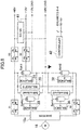
- a vehicle drive system 10 is mounted in a vehicle 1.
- the vehicle drive system 10 includes: an engine 12 that drives rear wheels 2a; a force transmission mechanism 14 that transmits driving force to the rear wheels 2a; a main drive motor 16 that drives the rear wheels 2a; sub-drive motors 20 that drive front wheels 2b; an inverter 15a electrically connected to the main drive motor 16; an inverter 15b electrically connected to the sub-drive motors 20; a battery unit 18 that supplies electric power to the inverters 15a and 15b; a control unit 24; and a fuel tank 30 that stores fuel to be supplied to the engine 12. That is, the vehicle drive system 10 is a hybrid drive system.
- the engine 12 is an internal combustion engine for generating driving force for the rear wheels 2a that are main drive wheels of the vehicle 1, which is a rotary engine in this embodiment.
- the engine 12 may otherwise be an engine other than the rotary engine, such as a reciprocating engine.
- the engine 12 is placed in the front part of the vehicle 1 and drives the rear wheels 2a through the force transmission mechanism 14.
- the force transmission mechanism 14 is configured to transmit the driving force generated by the engine 12 to the rear wheels 2a that are the main drive wheels.
- the force transmission mechanism 14 includes a propeller shaft 14a connected to the engine 12, a clutch 14b, and a transmission 14c that is a stepped gearbox.
- the propeller shaft 14a extends from the engine 12 placed in the front part of the vehicle 1 toward the rear of the vehicle 1 through a propeller shaft tunnel (not shown).
- the rear end of the propeller shaft 14a is connected to the transmission 14c via the clutch 14b.
- An output axis of the transmission 14c is connected to axles (not shown) of the rear wheels 2a, to drive the rear wheels 2a.
- the main drive motor 16 is an electric motor for generating driving force for the rear wheels 2a that are the main drive wheels of the vehicle 1, placed adjacent to the engine 12 on the rear side of the engine 12.
- the main drive motor 16 is serially connected with the engine 12, so that the driving force generated by the main drive motor 16 is also transmitted to the rear wheels 2a through the force transmission mechanism 14.
- a 25 kW permanent magnet synchronous motor driven at 48V is used as the main drive motor 16.
- the inverter 15a placed adjacent to the main drive motor 16, converts DC electric power supplied from the battery unit 18 to AC electric power and supplies the power to the main drive motor 16.
- the sub-drive motors 20 are electric motors for generating driving force for the front wheels 2b that are sub-drive wheels and, in this embodiment, are in-wheel motors housed in the front wheels 2b. In this embodiment, 17 kW induction motors are used as the sub-drive motors 20.
- the inverter 15b converts DC electric power supplied from the battery unit 18 to AC electric power and supplies the power to the sub-drive motors 20.
- the battery unit 18 is placed behind a seat 3 and in front of the fuel tank 30.
- the battery unit 18 includes four batteries 18a, 18b, 18c, and 18d.
- Each of the batteries 18a to 18d, having an output voltage of 48V, includes four serially-connected 12V battery cells inside.
- the batteries 18a and 18b are electrically connected in series and fixed in the battery unit 18.
- the connection node of the batteries 18a and 18b i.e., the negative pole of the battery 18a and the positive pole of the battery 18b are connected to the ground, in common with the inverter 15a.
- the battery 18c is connected in parallel with the battery 18a, and the battery 18d is connected in parallel with the battery 18b.
- the batteries 18c and 18d are battery cartridges removably loaded into the battery unit 18.
- the battery unit 18 is configured so that, once the cartridge batteries 18c and 18d are loaded thereinto, the battery 18c is connected in parallel with the battery 18a and the battery 18d is connected in parallel with the battery 18b.
- the control unit 24 is configured to control the engine 12, the inverter 15a electrically connected with the main drive motor 16, and the inverter 15b electrically connected with the sub-drive motors 20 whereby the vehicle 1 can execute an engine cruise mode and a motor cruise mode appropriately.
- the control unit 24 can be constituted by a microprocessor, a memory, an interface circuit, and a program for actuating these (none of these is shown).
- Switching control between the engine cruise mode and the motor cruise mode is performed as follows, for example. It is assumed that the vehicle 1 is provided with a switch for selecting the engine cruise mode or the motor cruise mode.
- the mode is set at the motor cruise mode in which the vehicle cruises at a comparatively low speed, repeating start and stop, on a city street.
- the control unit 24 controls to supply electric power from the battery unit 18 to the inverter 15a to drive the main drive motor 16. Meanwhile, the control unit 24 controls not to supply fuel to the engine 12 to prevent the engine 12 from producing torque.
- the vehicle 1 purely functions as an electric vehicle (EV).
- the motor cruise mode is maintained as long as an acceleration of a given amount or greater is not exerted, and the vehicle 1 is driven by the main drive motor 16.
- the control unit 24 starts supply of fuel to the engine 12, whereby the engine 12 produces torque. Meanwhile, the control unit 24 stops the control on the inverter 15a to stop the drive by the main drive motor 16. The driver then can enjoy a feeling of driving the vehicle 1 driven by the engine 12.
- FIG. 3 shows a configuration of main circuits related to motor driving in the vehicle drive system of this embodiment.
- FIG. 4 shows a configuration of main circuits related to motor driving according to a comparative example.
- a connector 4a of the battery unit 18 and a connector 4b of the inverter 15a are electrically connected through three wires 5 (5a, 5b, and 5c).
- the batteries 18a and 18b are serially connected, and their connection node, i.e., the negative pole of the battery 18a and the positive pole of the battery 18b are connected to the ground.
- the wire 5a is connected to the positive pole of the battery 18a
- the wire 5b is connected to the negative pole of the battery 18a and the positive pole of the battery 18b
- the wire 5c is connected to the negative pole of the battery 18b. That is, voltages of ⁇ 48V are output from the battery unit 18.
- capacitors 15c and 15d are serially connected, and their connection node is connected to the wire 5b.
- the other end of the capacitor 15c is connected to the wire 5a, and the other end of the capacitor 15d is connected to the wire 5c. That is, a voltage of 96 V is applied to the capacitors 15c and 15d.
- Safety measures against high voltage are basically unnecessary for a low voltage less than 60 V, and low-cost elements and parts can be used. Specifically, in the configuration of FIG. 3 , inexpensive ones for low voltage can be used as the connectors 4a and 4b and the wires 5. Also, the weight of harnesses, etc. can be widely reduced.
- connection node of the serially-connected batteries 18a and 18b since the connection node of the serially-connected batteries 18a and 18b is grounded in the battery unit 18, a positive voltage of the same value as the output voltage of the battery 18a and a negative voltage of which the absolute value is the same as the output voltage of the battery 18b, with reference to the ground, are output from the battery unit 18. This decreases the voltage of the output of the battery unit 18, and thus can keep the vehicle weight and cost from increasing.
- a 3-level inverter is used as the inverter 15a.
- FIGS. 5A and 5B are views showing an outline of a 3-level inverter, where FIG. 5A shows a circuit configuration and FIG. 5B shows a waveform of the output voltage.
- FIG. 5A in a 3-level inverter, two serially-connected switching elements are placed in each of the positive side and the negative side. For control of a 3-phase motor, a total of 12 (2 ⁇ 2 ⁇ 3) switching elements are necessary. When ⁇ 48V are given as the battery voltages, a motor drive voltage of 96 V can be generated by controlling the switching elements, as shown in FIG. 5B .
- MOSFETs low in withstand voltage compared to IGBTs can be used.
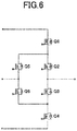
- FIG. 6 shows a configuration example of an inverter circuit corresponding to one phase.
- the connection node of switching elements Q5 and Q6 is connected to the ground.
- the same drive signal given to a switching element Q3 is given, and to the switching element Q6, the same drive signal given a switching element Q2 is given.
- FIG. 7 shows examples of drive waveforms for switching elements in each phase and interphase voltages.
- the difference between voltages in two phases driven according to the drive waveforms is to be an interphase voltage between the two phases.
- the difference between the voltage in u phase driven according to drive waveforms Q1u to Q4u and the voltage in v phase driven according to drive waveforms Q1v to Q4v is to be an interphase voltage Vu-v.
- a motor drive voltage of 96 V can be generated from the battery voltages of ⁇ 48V, for example.
- FIG. 8 shows an example of a circuit configuration related to battery control in the vehicle drive system of this embodiment.
- Batt1, Batt2, Batt3, and Batt4 are each 48V batteries and respectively correspond to the batteries 18a, 18b, 18c, and 18d in the configuration of FIG. 2 .
- the negative pole of the battery Batt1 and the positive pole of the battery Batt2 are connected, and their connection node is grounded (a neutral point).
- the battery Batt3 is connected in parallel with the battery Batt1, and the battery Batt4 is connected in parallel with the battery Batt2.
- the batteries Batt3 and Batt4 may be omitted.
- a switch S1 is inserted between the positive pole of the battery Batt1 and the inverter 15a, and a switch S2 is inserted between the negative pole of the battery Batt2 and the inverter 15a. Also, it is made possible to supply 48V power and 12V power from the battery Batt1 to electric components inside the vehicle 1.
- a switch S3 is inserted between the positive pole of the battery Batt1 and a 48V power line.
- a switch S0 is inserted between the positive pole of one battery cell in the battery Batt1 and a 12V power line.
- the switches S0 to S3 are constituted by MOSFETs, for example.
- a DC/DC converter 41 converts 48V power supplied from the battery Batt1 to 12V power and outputs the converted power.
- a balance circuit 30 (indicated as balance 0 in FIG. 8 ) is provided for the batteries Batt1 and Batt2.
- the balance circuit 30 has a function of balancing the charged amounts of the batteries Batt1 and Batt2 by performing charge/discharge control between the batteries Batt1 and Batt2.
- cell balance circuits 31, 32, 33, and 34 (indicated as balances 1 to 4 in FIG. 8 ) are respectively provided for the batteries Batt1, Batt2, Batt3, and Batt4.
- the cell balance circuits 31 to 34 have a function of balancing the charged amounts of battery cells in the corresponding batteries.
- a controller 42 performs on/off control of the switches S0 to S3 and control of the balance circuit 30 and the cell balance circuits 31 to 34.
- the controller 42 can be constituted by a microprocessor, a memory, an interface circuit, and programs for actuating these.
- the controller 42 may be configured integrally with the control unit 24 shown in FIG. 2 or separately from it.
- FIG. 9 shows a circuit configuration example of the balance circuit 30.
- the balance circuit 30 of FIG. 9 includes switches S4 and S5 serially arranged between the positive and negative poles of the battery Batt1, switches S6 and S7 serially arranged between the positive and negative poles of the battery Batt2, and a capacitor C30 provided between the node of the switches S4 and S5 and the node of the switches S6 and S7.
- a capacitor C30 provided between the node of the switches S4 and S5 and the node of the switches S6 and S7.
- FIG. 10 shows a circuit configuration example of the cell balance circuit 31.
- the battery Batt1 includes four serially-connected battery cells 181 to 184.
- the cell balance circuit 31 of FIG. 10 includes switches S11 to S14 and a capacitor C31a as a configuration for balancing the charged amounts of the battery cells 181 and 182.
- the cell balance circuit 31 also includes switches S15 to S18 and a capacitor C31b as a configuration for balancing the charged amounts of the battery cells 183 and 184.
- the cell balance circuit 31 includes switches S21 to S24 and a capacitor C31c as a configuration for balancing the charged amount of the battery cells 181 and 182 and the charged amount of the battery cells 183 and 184. Note that detailed description on the operation of the cell balance circuit 31 is omitted here as it will be easily known by analogy from the operation of the balance circuit 30 that will be described hereinafter.
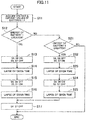
- FIG. 11 is a flowchart showing the operation of the balance circuit 30.
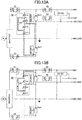
- FIGS. 12A and 12B show the operation of transferring energy from the battery Batt1 to the battery Batt2
- FIGS. 13A and 13B show the operation of transferring energy from the battery Batt2 to the battery Batt1. Note that, in FIGS. 12A, 12B , 13A, and 13B , illustration of the batteries Batt3 and Batt4 and components related to these batteries is omitted for simplification of the drawings.
- the controller 42 acquires the voltage values and current values of the batteries Batt1 and Batt2 (step S11), and determines which of the batteries Batt1 and Batt2 has greater energy.
- the balance circuit 30 operates to transfer the energy of the battery Batt1 to the battery Batt2. That is, the controller 42 turns on the switches S4 and S6 and turns off the switches S5 and S7 in the balance circuit 30 (step S13). By this switching, as shown in FIG. 12A , the energy of the battery Batt1 starts to be transferred to the capacitor C30. After the lapse of a given time (step S14), the controller 42 turns off the switches S4 and S6 and turns on the switches S5 and S7 in the balance circuit 30 (step S15). By this switching, as shown in FIG. 12B , the energy stored in the capacitor C30 starts to be transferred to the battery Batt2. After the lapse of a given time (step S16), the controller 42 turns off the switches S4 to S7 (step S17). By this operation of the balance circuit 30, part of the energy of the battery Batt1 can be transferred to the battery Batt2.
- the balance circuit 30 operates to transfer the energy of the battery Batt2 to the battery Batt1. That is, the controller 42 turns off the switches S4 and S6 and turns on the switches S5 and S7 in the balance circuit 30 (step S22). By this switching, as shown in FIG. 13A , the energy of the battery Batt2 starts to be transferred to the capacitor C30. After the lapse of a given time (step S23), the controller 42 turns on the switches S4 and S6 and turns off the switches S5 and S7 in the balance circuit 30 (step S24). By this switching, as shown in FIG. 13B , the energy stored in the capacitor C30 starts to be transferred to the battery Batt1. After the lapse of a given time (step S25), the controller 42 turns off the switches S4 to S7 (step S17). By this operation of the balance circuit 30, part of the energy of the battery Batt2 can be transferred to the battery Batt1.
- the battery Batt1 may be determined to have greater energy than the battery batt2 if the energy of the battery Batt1 is greater than that of the battery Batt2 by a given value or larger.
- the battery Batt2 may be determined to have greater energy than the battery Batt1 if the energy of the battery Batt2 is greater than that of the battery Batt1 by a given value or larger.
- the given time during which energy from the battery Batt1 or Batt2 is stored in the capacitor C30 may be determined in advance based on the capacity of the capacitor C30 and the capacities of the batteries Batt1 and Batt2.
- the balance circuit 30 can be operated in the motor cruise mode in which the vehicle 1 is cruising by the motor and also in the engine cruise mode.
- an inductor L may be provided on an electric route between the connection node of the batteries Batt1 and Batt2 and the connection node of the switches S5 and S6. With this, energy can be transferred to the capacitor C30 by use of LC resonance even when the voltage difference between the batteries Batt1 and Batt2 is small.
- the cell balance circuits 31 to 34 may be omitted. In the battery Batt1, however, since 12V power is output from one battery cell, the charged amounts may be unbalanced among the battery cells. It is therefore preferable to provide the cell balance circuit 31 for the battery Batt1.
- the third and fourth batteries 18c and 18d are cartridges configured to be removably loaded into the battery part 18.
- a configuration example of a battery cartridge according to this embodiment will be described hereinafter.
- FIG. 14 shows an appearance example of a battery cartridge according to this embodiment
- FIG. 15 shows a configuration example of an electric connecting part of the battery cartridge.
- the battery cartridge 50 has a roughly quadrangular prism shape, where the longitudinal edges of the side faces are rounded.
- an electric connecting part 52 including a positive pole 52a and a negative pole 52b is formed on one end face 51 of the battery cartridge 50.
- a handle 54 is formed on the other end face 53.
- the battery cartridge 50 is slightly tapered from the end face 53 toward the end face 51.
- FIG. 16 shows a configuration example of a portion of the battery unit 18 for loading of the battery cartridge 50.
- the battery unit has a hole 60 into which the battery cartridge 50 is to be loaded.
- the hole 60 has a bottom 61 on which an electric connecting part 62 is formed.
- An elastic member 63 is provided on the side wall of the hole 60.
- the inverter 15a is controlled so that the motor drive voltage output from the inverter 15a is higher than the output voltage of the battery Batt1 and also than the output voltage of the battery Batt2.
- the battery unit 18 is configured so that the cartridge batteries 18c and 18d are removably loaded, and the loaded battery 18c is connected in parallel with the battery 18a and the loaded battery 18d is connected in parallel with the battery 18b. This makes it possible to use an auxiliary battery and also makes replacement of the auxiliary battery easy, whereby the problem of the cruising distance can be alleviated.
- At least one of the batteries 18a and 18b may be a battery cartridge.
- the configuration example of the battery cartridge and the battery unit shown in FIGS. 14 to 16 may be applied to at least one of the batteries 18a and 18b. This makes it easy to replace at least one of the batteries 18a and 18b, whereby the problem of the cruising distance can be alleviated.
- the vehicle 1 is a one-row seat vehicle, and the battery unit 18 is placed behind the seat 3 and in front of the fuel tank 30. It is preferable to place the battery unit 18 at a position like this, i.e., behind a rearmost seat and in front of the fuel tank. At such a position, a worker can easily access the battery unit, and thus battery replacement becomes further easy. Also, luggage space can be secured.
- the placement position of the battery unit is not limited to this indicated in this embodiment, but may be under the floor, for example. Otherwise, the battery unit may be divided and placed at a plurality of positions. For example, a portion of the battery unit that houses a battery cartridge may be placed at a position behind a rear seat easily accessible to a worker, and a portion thereof where a battery is fixed may be placed under the floor.
- the balance circuit 30 that balances the charged amounts of the batteries Batt1 and Batt2 by performing charge/discharge control between the batteries Batt1 and Batt2 is provided.
- the configuration may be made to use a battery cartridge in the battery unit 18 as in this embodiment.
- the inverter 15a is a 3-level inverter in this embodiment, the present disclosure is not limited to this.
- the inverter 15a may be a multi-level inverter such as a 4-level inverter and a 5-level inverter.
- the inverter 15a may be an inverter that is not a multi-level inverter but of which the operation is controlled so that the motor drive voltage output therefrom is higher than the output voltage of the battery Batt1 and also than the output voltage of the battery Batt2.
- the battery unit 18 includes the batteries 18a and 18b fixed in the vehicle 1 and the removable cartridge batteries 18c and 18d in this embodiment, the number of batteries and the forms thereof are not limited to these.
- the battery unit may include two batteries fixed in the vehicle and no cartridge batteries.
- the voltage of each battery, the number of battery cells constituting the battery, and the voltage of each battery cell are not limited to those described in this embodiment. It is however preferable that the output voltage of each battery is less than 60V, for example, from the standpoint of the objective of the present disclosure of reducing the output voltage of the battery unit to keep the vehicle weight and cost from increasing.
- vehicle drive system of this embodiment is a hybrid drive system
- present disclosure may also be applied to a motor drive system.
Landscapes
- Engineering & Computer Science (AREA)
- Mechanical Engineering (AREA)
- Transportation (AREA)
- Power Engineering (AREA)
- Combustion & Propulsion (AREA)
- Chemical & Material Sciences (AREA)
- Life Sciences & Earth Sciences (AREA)
- Sustainable Development (AREA)
- Sustainable Energy (AREA)
- Automation & Control Theory (AREA)
- Electric Propulsion And Braking For Vehicles (AREA)
- Charge And Discharge Circuits For Batteries Or The Like (AREA)
- Secondary Cells (AREA)
- Battery Mounting, Suspending (AREA)
Abstract
Description
- The present disclosure relates to a vehicle drive system that uses a motor for cruising and a battery.
- A vehicle drive system for driving a motor for cruising by a high-voltage battery has been conventionally known. Since the power output of the motor depends on the current and the voltage (P = I · V · cosθ), to increase the output of the motor, it is effective to raise the voltage of the battery. In general, a high-voltage battery of 60V or higher is used for driving a motor for cruising.
- In a device using a high-voltage battery, measures against high voltage are necessary for parts and wires of the device, and this leads to increase in cost and weight. For example, wires for connecting an inverter with the battery become large in size and heavy. Also, as connectors for the inverter and the battery, expensive ones resistant to high voltage must be used. On the other hand, since the current value required for attaining given motor output becomes smaller as the voltage is higher (P = I · V · cosθ), motor loss can be reduced (Ploss = R · I2). This improves the electric mileage of the vehicle. In recent years, a configuration having a higher-voltage battery is in the mainstream, placing higher priority on the merit of improving the electric mileage than the demerit of increasing the vehicle weight and cost.
-
Japanese Unexamined Patent Publication No. 2019-162964 - In general, a capacitor can supply a larger current momentarily than a normal battery. In the configuration of the cited patent document, such a capacitor with good responsiveness is used for acceleration at the startup of a vehicle, for example. However, since a capacitor is small in energy density, it is difficult for the capacitor to supply electric power to the motor for a long time. It is therefore preferable to use a battery, not a capacitor, from the standpoint of securing the cruising distance.
- An objective of the present disclosure is providing a vehicle drive system using a motor for cruising, capable of increasing the output of the motor, achieving long-time power supply to the motor, and alleviating a problem of the cruising distance while keeping the vehicle weight and cost from increasing.
- The inventors of the present disclosure have attained the following findings as a result of experiments and examinations on the vehicle drive system having the configuration described above.
- That is, in the above-described vehicle drive system, the connection node of serially connected first and second batteries is connected to the ground, to reduce the voltage output from the battery unit. Also, a 3-level inverter is used as the inverter, so that a motor drive voltage higher than the battery voltage is generated. It is therefore possible to implement a vehicle drive system with a reduced weight, low cost, and high motor output.
- As a result of experiments by the present inventers, however, it has been found that the vehicle drive system having the above-described configuration fails to secure output performance as excellent as expected. From our examinations, the reason for this has been found to be variations in charged amount (SOC)/voltage between the batteries.
- That is, with variations in charged amount/voltage between the batteries that supply power to the inverter, the amplitude of the motor drive voltage varies, causing torque fluctuations of the motor. In vehicle driving, torque fluctuations of the motor become a cause of greatly impairing driving comfort and therefore must be kept to a minimum. To keep torque fluctuations to a minimum, however, the inverter output is forced to be restricted to suit to one of the batteries lower in charged amount/voltage. This raises a problem of failing to make full use of the potential of the vehicle drive system.
- The present inventors have thus attained the findings that, in order to adequately secure the motor output performance in the vehicle drive system having the above-described configuration, it is important to strike a balance in charged amount/voltage between the batteries that supply power to the inverter. Based on the findings, the present inventors have invented a configuration as described below.
- That is, according to the present disclosure, a vehicle drive system includes: a motor that generates driving force for drive wheels; an inverter electrically connected to the motor; a battery unit that supplies electric power to the inverter; and a control unit that controls operation of the inverter, wherein the battery unit is configured to house a first and second batteries, and configured so that, when the first and second batteries are housed, the first and second batteries are serially connected, and a negative pole of the first battery and a positive pole of the second battery that are mutually connected are grounded, the control unit controls the operation of the inverter so that a voltage output from the inverter to the motor is higher than an output voltage of the first battery and also than an output voltage of the second battery, and at least one of the first and second batteries is a battery cartridge configured to be removably loaded into the battery unit.
- With the above configuration, since the connection node of the serially-connected first and second batteries is grounded in the battery unit, a positive voltage of the same value as the output voltage of the first battery and a negative voltage of which the absolute value is the same as the output voltage of the second battery, with reference to the ground, are output from the battery unit. The operation of the inverter is controlled so that the motor drive voltage output from the inverter is higher than the output voltage of the first battery and also than the output voltage of the second battery. This makes it possible to increase the output of the motor while reducing the voltage of the output of the battery unit to keep the vehicle weight and cost from increasing. Moreover, since a low-voltage battery can be used, at least one of the first and second batteries can be a battery cartridge configured to be removably loaded into the battery unit. This makes battery replacement easy, and thus the problem of the cruising distance can be alleviated.
- The battery cartridge may have a roughly quadrangular prism shape, with a first electric connecting part including a positive pole and a negative pole formed on one of end faces of the battery cartridge and a handle formed on the other end face.
- With the above configuration, handling of the battery cartridge becomes easy, and this makes the replacement easy.
- Further, the battery unit may have a hole for loading the battery cartridge, and the hole may have a second electric connecting part on its bottom and be configured so that, when the battery cartridge is loaded into the hole with the one end face of the battery cartridge facing the bottom of the hole, the first electric connecting part is electrically connected with the second electric connecting part.
- With the above configuration, loading of the battery cartridge into the battery unit becomes easy.
- Alternatively, according to the present disclosure, a vehicle drive system includes: a motor that generates driving force for drive wheels; an inverter electrically connected to the motor; a battery unit that supplies electric power to the inverter; and a control unit that controls operation of the inverter, wherein the battery unit has serially-connected first and second batteries, and a negative pole of the first battery and a positive pole of the second battery that are mutually connected are grounded, the control unit controls the operation of the inverter so that a voltage output from the inverter to the motor is higher than an output voltage of the first battery and also than an output voltage of the second battery, and the battery unit is configured so that third and fourth batteries each in a form of a cartridge are removably loaded, and the loaded third battery is connected in parallel with the first battery and the loaded fourth battery is connected in parallel with the second battery.
- With the above configuration, since the connection node of the serially-connected first and second batteries is grounded in the battery unit, a positive voltage of the same value as the output voltage of the first battery and a negative voltage of which the absolute value is the same as the output voltage of the second battery, with reference to the ground, are output from the battery unit. The operation of the inverter is controlled so that the motor drive voltage output from the inverter is higher than the output voltage of the first battery and also than the output voltage of the second battery. This makes it possible to increase the output of the motor while reducing the voltage of the output of the battery unit to keep the vehicle weight and cost from increasing. Moreover, the battery unit is configured so that the third and fourth batteries each in a form of a cartridge are removably loaded, and the loaded third battery is connected in parallel with the first battery and the loaded fourth battery is connected in parallel with the second battery. This makes it possible to use an auxiliary battery and also makes replacement of the auxiliary battery easy, whereby the problem of the cruising distance can be alleviated.
- The third and fourth batteries each may have a roughly quadrangular prism shape, with a first electric connecting part including a positive pole and a negative pole formed on one of end faces of the battery and a handle formed on the other end face.
- With the above configuration, handling of the third and fourth batteries becomes easy, and this makes the replacement easy.
- Further, the battery unit may have a hole for loading each of the third and fourth batteries, and the hole may have a second electric connecting part on its bottom and be configured so that, when the third or fourth battery is loaded into the hole with the one end face of the battery facing the bottom of the hole, the first electric connecting part is electrically connected with the second electric connecting part.
- With the above configuration, loading of the third and fourth batteries into the battery unit becomes easy.
- In the vehicle drive system described above, the battery unit may be placed behind a rearmost seat and in front of a fuel tank in the vehicle.
- With the above configuration, a worker can easily access the battery unit, and thus battery replacement becomes further easy. Also, luggage space can be secured.
- The vehicle drive system described above may further include a balance circuit that balances charged amounts of the first and second batteries by performing charge/discharge control between the first and second batteries
- With the above configuration, the charged amounts of the first and second batteries can be balanced by performing charge/discharge control between the first and second batteries by the balance circuit. It is therefore possible to make full use of the potential of the vehicle drive system and adequately secure the motor output performance while keeping the torque fluctuations of the motor to a minimum.
- In the vehicle drive system described above, the inverter may be a multi-level inverter.
- With the above configuration, the operation of the inverter can be easily controlled so that the voltage output from the inverter to the motor becomes higher than the output voltage of the first battery and also than the output voltage of the second battery.
- In the vehicle drive system described above, the output voltages of the first and second batteries are each less than 60V, for example.
- As described above, according to the present disclosure, in a vehicle drive system using a motor for cruising, it is possible to increase the output of the motor, achieve long-time power supply to the motor, and alleviate the problem of the cruising distance while keeping the vehicle weight and cost from increasing.
-
-
FIG. 1 shows an example of the layout of a vehicle drive system of an embodiment mounted in a vehicle. -
FIG. 2 shows a configuration example of the vehicle drive system of the embodiment. -
FIG. 3 shows a main circuit configuration for motor driving in the vehicle drive system of the embodiment. -
FIG. 4 shows a main circuit configuration for motor driving according to a comparative example. -
FIGS. 5A and 5B show a configuration outline and an operation, respectively, of a 3-level inverter. -
FIG. 6 shows an inverter circuit of one phase of the 3-level inverter. -
FIG. 7 shows a detailed operation diagram of the 3-level inverter. -
FIG. 8 shows an example of a circuit configuration related to battery control in the vehicle drive system of the embodiment. -
FIG. 9 shows a circuit configuration example of a balance circuit inFIG. 8 . -
FIG. 10 shows a circuit configuration of a cell balance circuit inFIG. 8 . -
FIG. 11 is a flowchart showing the operation of the balance circuit. -
FIGS. 12A and 12B are views showing the operation of transferring energy frombattery 1 tobattery 2. -
FIGS. 13A and 13B are views showing the operation of transferring energy frombattery 2 tobattery 1. -
FIG. 14 shows an appearance example of a battery cartridge. -
FIG. 15 shows a configuration example of an electric connecting part of the battery cartridge. -
FIG. 16 shows a configuration example of a portion of a battery unit into which the battery cartridge is loaded. - An illustrative embodiment will be described hereinafter in detail with reference to the accompanying drawings.
-
FIG. 1 shows an example of the layout of a vehicle drive system of this embodiment mounted in a vehicle, illustrated as a phantom view of the vehicle viewed from a side.FIG. 2 shows a configuration example of the vehicle drive system of this embodiment. - As shown in
FIGS. 1 and2 , avehicle drive system 10 is mounted in avehicle 1. Thevehicle drive system 10 includes: anengine 12 that drivesrear wheels 2a; aforce transmission mechanism 14 that transmits driving force to therear wheels 2a; amain drive motor 16 that drives therear wheels 2a;sub-drive motors 20 that drivefront wheels 2b; aninverter 15a electrically connected to themain drive motor 16; aninverter 15b electrically connected to thesub-drive motors 20; abattery unit 18 that supplies electric power to theinverters control unit 24; and afuel tank 30 that stores fuel to be supplied to theengine 12. That is, thevehicle drive system 10 is a hybrid drive system. - The
engine 12 is an internal combustion engine for generating driving force for therear wheels 2a that are main drive wheels of thevehicle 1, which is a rotary engine in this embodiment. Theengine 12 may otherwise be an engine other than the rotary engine, such as a reciprocating engine. Theengine 12 is placed in the front part of thevehicle 1 and drives therear wheels 2a through theforce transmission mechanism 14. - The
force transmission mechanism 14 is configured to transmit the driving force generated by theengine 12 to therear wheels 2a that are the main drive wheels. Theforce transmission mechanism 14 includes apropeller shaft 14a connected to theengine 12, a clutch 14b, and atransmission 14c that is a stepped gearbox. Thepropeller shaft 14a extends from theengine 12 placed in the front part of thevehicle 1 toward the rear of thevehicle 1 through a propeller shaft tunnel (not shown). The rear end of thepropeller shaft 14a is connected to thetransmission 14c via the clutch 14b. An output axis of thetransmission 14c is connected to axles (not shown) of therear wheels 2a, to drive therear wheels 2a. - The
main drive motor 16 is an electric motor for generating driving force for therear wheels 2a that are the main drive wheels of thevehicle 1, placed adjacent to theengine 12 on the rear side of theengine 12. Themain drive motor 16 is serially connected with theengine 12, so that the driving force generated by themain drive motor 16 is also transmitted to therear wheels 2a through theforce transmission mechanism 14. In this embodiment, a 25 kW permanent magnet synchronous motor driven at 48V is used as themain drive motor 16. - The
inverter 15a, placed adjacent to themain drive motor 16, converts DC electric power supplied from thebattery unit 18 to AC electric power and supplies the power to themain drive motor 16. - The
sub-drive motors 20 are electric motors for generating driving force for thefront wheels 2b that are sub-drive wheels and, in this embodiment, are in-wheel motors housed in thefront wheels 2b. In this embodiment, 17 kW induction motors are used as thesub-drive motors 20. - The
inverter 15b converts DC electric power supplied from thebattery unit 18 to AC electric power and supplies the power to thesub-drive motors 20. - The
battery unit 18 is placed behind aseat 3 and in front of thefuel tank 30. In this embodiment, thebattery unit 18 includes fourbatteries batteries 18a to 18d, having an output voltage of 48V, includes four serially-connected 12V battery cells inside. - The
batteries battery unit 18. As will be described later, the connection node of thebatteries battery 18a and the positive pole of thebattery 18b are connected to the ground, in common with theinverter 15a. Thebattery 18c is connected in parallel with thebattery 18a, and thebattery 18d is connected in parallel with thebattery 18b. In this case, thebatteries battery unit 18. Thebattery unit 18 is configured so that, once thecartridge batteries battery 18c is connected in parallel with thebattery 18a and thebattery 18d is connected in parallel with thebattery 18b. - The
control unit 24 is configured to control theengine 12, theinverter 15a electrically connected with themain drive motor 16, and theinverter 15b electrically connected with thesub-drive motors 20 whereby thevehicle 1 can execute an engine cruise mode and a motor cruise mode appropriately. Specifically, thecontrol unit 24 can be constituted by a microprocessor, a memory, an interface circuit, and a program for actuating these (none of these is shown). - Switching control between the engine cruise mode and the motor cruise mode is performed as follows, for example. It is assumed that the
vehicle 1 is provided with a switch for selecting the engine cruise mode or the motor cruise mode. - The mode is set at the motor cruise mode in which the vehicle cruises at a comparatively low speed, repeating start and stop, on a city street. In the motor cruise mode, the
control unit 24 controls to supply electric power from thebattery unit 18 to theinverter 15a to drive themain drive motor 16. Meanwhile, thecontrol unit 24 controls not to supply fuel to theengine 12 to prevent theengine 12 from producing torque. In this case, thevehicle 1 purely functions as an electric vehicle (EV). - Even when the
vehicle 1 is cruising at a speed higher than a given speed, the motor cruise mode is maintained as long as an acceleration of a given amount or greater is not exerted, and thevehicle 1 is driven by themain drive motor 16. - Assume here that the driver operates the switch to change the mode to the engine cruise mode and depresses the accelerator pedal. In the engine cruise mode, the
control unit 24 starts supply of fuel to theengine 12, whereby theengine 12 produces torque. Meanwhile, thecontrol unit 24 stops the control on theinverter 15a to stop the drive by themain drive motor 16. The driver then can enjoy a feeling of driving thevehicle 1 driven by theengine 12. -
FIG. 3 shows a configuration of main circuits related to motor driving in the vehicle drive system of this embodiment.FIG. 4 shows a configuration of main circuits related to motor driving according to a comparative example. - As shown in
FIG. 3 , in this embodiment, aconnector 4a of thebattery unit 18 and aconnector 4b of theinverter 15a are electrically connected through three wires 5 (5a, 5b, and 5c). In thebattery unit 18, thebatteries battery 18a and the positive pole of thebattery 18b are connected to the ground. Thewire 5a is connected to the positive pole of thebattery 18a, thewire 5b is connected to the negative pole of thebattery 18a and the positive pole of thebattery 18b, and thewire 5c is connected to the negative pole of thebattery 18b. That is, voltages of ±48V are output from thebattery unit 18. - In the
inverter 15a,capacitors wire 5b. The other end of thecapacitor 15c is connected to thewire 5a, and the other end of thecapacitor 15d is connected to thewire 5c. That is, a voltage of 96 V is applied to thecapacitors - Safety measures against high voltage are basically unnecessary for a low voltage less than 60 V, and low-cost elements and parts can be used. Specifically, in the configuration of
FIG. 3 , inexpensive ones for low voltage can be used as theconnectors wires 5. Also, the weight of harnesses, etc. can be widely reduced. - On the contrary, in the configuration of
FIG. 4 , in abattery unit 118,batteries battery unit 118. Therefore, as aconnector 104a in thebattery unit 118 and aconnector 104b in aninverter 115a, high voltage-support ones must be used. Also, aswires 105 for connecting theconnectors - In other words, in the configuration of this embodiment, since the connection node of the serially-connected
batteries battery unit 18, a positive voltage of the same value as the output voltage of thebattery 18a and a negative voltage of which the absolute value is the same as the output voltage of thebattery 18b, with reference to the ground, are output from thebattery unit 18. This decreases the voltage of the output of thebattery unit 18, and thus can keep the vehicle weight and cost from increasing. - Further, in this embodiment, to attain a motor drive voltage higher than the
battery voltage 48V, a 3-level inverter is used as theinverter 15a. -
FIGS. 5A and 5B are views showing an outline of a 3-level inverter, whereFIG. 5A shows a circuit configuration andFIG. 5B shows a waveform of the output voltage. As shown inFIG. 5A , in a 3-level inverter, two serially-connected switching elements are placed in each of the positive side and the negative side. For control of a 3-phase motor, a total of 12 (2 × 2 × 3) switching elements are necessary. When ±48V are given as the battery voltages, a motor drive voltage of 96 V can be generated by controlling the switching elements, as shown inFIG. 5B . As the switching elements, MOSFETs low in withstand voltage compared to IGBTs can be used. -
FIG. 6 shows a configuration example of an inverter circuit corresponding to one phase. InFIG. 6 , the connection node of switching elements Q5 and Q6 is connected to the ground. To the switching element Q5, the same drive signal given to a switching element Q3 is given, and to the switching element Q6, the same drive signal given a switching element Q2 is given. -
FIG. 7 shows examples of drive waveforms for switching elements in each phase and interphase voltages. As shown inFIG. 7 , the difference between voltages in two phases driven according to the drive waveforms is to be an interphase voltage between the two phases. For example, the difference between the voltage in u phase driven according to drive waveforms Q1u to Q4u and the voltage in v phase driven according to drive waveforms Q1v to Q4v is to be an interphase voltage Vu-v. By controlling the inverter as shown inFIG. 7 , a motor drive voltage of 96 V can be generated from the battery voltages of ±48V, for example. -
FIG. 8 shows an example of a circuit configuration related to battery control in the vehicle drive system of this embodiment. In the configuration ofFIG. 8 , Batt1, Batt2, Batt3, and Batt4 are each 48V batteries and respectively correspond to thebatteries FIG. 2 . The negative pole of the battery Batt1 and the positive pole of the battery Batt2 are connected, and their connection node is grounded (a neutral point). The battery Batt3 is connected in parallel with the battery Batt1, and the battery Batt4 is connected in parallel with the battery Batt2. The batteries Batt3 and Batt4 may be omitted. - A switch S1 is inserted between the positive pole of the battery Batt1 and the
inverter 15a, and a switch S2 is inserted between the negative pole of the battery Batt2 and theinverter 15a. Also, it is made possible to supply 48V power and 12V power from the battery Batt1 to electric components inside thevehicle 1. A switch S3 is inserted between the positive pole of the battery Batt1 and a 48V power line. A switch S0 is inserted between the positive pole of one battery cell in the battery Batt1 and a 12V power line. The switches S0 to S3 are constituted by MOSFETs, for example. A DC/DC converter 41converts 48V power supplied from the battery Batt1 to 12V power and outputs the converted power. - A balance circuit 30 (indicated as balance 0 in
FIG. 8 ) is provided for the batteries Batt1 and Batt2. Thebalance circuit 30 has a function of balancing the charged amounts of the batteries Batt1 and Batt2 by performing charge/discharge control between the batteries Batt1 and Batt2. Also,cell balance circuits balances 1 to 4 inFIG. 8 ) are respectively provided for the batteries Batt1, Batt2, Batt3, and Batt4. Thecell balance circuits 31 to 34 have a function of balancing the charged amounts of battery cells in the corresponding batteries. - A
controller 42 performs on/off control of the switches S0 to S3 and control of thebalance circuit 30 and thecell balance circuits 31 to 34. Thecontroller 42 can be constituted by a microprocessor, a memory, an interface circuit, and programs for actuating these. Thecontroller 42 may be configured integrally with thecontrol unit 24 shown inFIG. 2 or separately from it. -
FIG. 9 shows a circuit configuration example of thebalance circuit 30. Thebalance circuit 30 ofFIG. 9 includes switches S4 and S5 serially arranged between the positive and negative poles of the battery Batt1, switches S6 and S7 serially arranged between the positive and negative poles of the battery Batt2, and a capacitor C30 provided between the node of the switches S4 and S5 and the node of the switches S6 and S7. By controlling on/off of the switches S4 to S7, energy can be transferred from one of the batteries Batt1 and Batt2 to the other through the capacitor C30. The operation of thebalance circuit 30 will be described later in detail. -
FIG. 10 shows a circuit configuration example of thecell balance circuit 31. Note that thecell balance circuits 32 to 34 may have a similar circuit configuration to that ofFIG. 10 . The battery Batt1 includes four serially-connectedbattery cells 181 to 184. Thecell balance circuit 31 ofFIG. 10 includes switches S11 to S14 and a capacitor C31a as a configuration for balancing the charged amounts of thebattery cells cell balance circuit 31 also includes switches S15 to S18 and a capacitor C31b as a configuration for balancing the charged amounts of thebattery cells cell balance circuit 31 includes switches S21 to S24 and a capacitor C31c as a configuration for balancing the charged amount of thebattery cells battery cells cell balance circuit 31 is omitted here as it will be easily known by analogy from the operation of thebalance circuit 30 that will be described hereinafter. - The operation of the
balance circuit 30 is as follows.FIG. 11 is a flowchart showing the operation of thebalance circuit 30.FIGS. 12A and 12B show the operation of transferring energy from the battery Batt1 to the battery Batt2, andFIGS. 13A and 13B show the operation of transferring energy from the battery Batt2 to the battery Batt1. Note that, inFIGS. 12A, 12B ,13A, and 13B , illustration of the batteries Batt3 and Batt4 and components related to these batteries is omitted for simplification of the drawings. - At the start of the operation of the
balance circuit 30, thecontroller 42 acquires the voltage values and current values of the batteries Batt1 and Batt2 (step S11), and determines which of the batteries Batt1 and Batt2 has greater energy. - If the battery Batt1 has greater energy than the battery Batt2 (YES in step S12), the
balance circuit 30 operates to transfer the energy of the battery Batt1 to the battery Batt2. That is, thecontroller 42 turns on the switches S4 and S6 and turns off the switches S5 and S7 in the balance circuit 30 (step S13). By this switching, as shown inFIG. 12A , the energy of the battery Batt1 starts to be transferred to the capacitor C30. After the lapse of a given time (step S14), thecontroller 42 turns off the switches S4 and S6 and turns on the switches S5 and S7 in the balance circuit 30 (step S15). By this switching, as shown inFIG. 12B , the energy stored in the capacitor C30 starts to be transferred to the battery Batt2. After the lapse of a given time (step S16), thecontroller 42 turns off the switches S4 to S7 (step S17). By this operation of thebalance circuit 30, part of the energy of the battery Batt1 can be transferred to the battery Batt2. - Contrarily, if the battery Batt2 has greater energy than the battery Batt1 (YES in step S21), the
balance circuit 30 operates to transfer the energy of the battery Batt2 to the battery Batt1. That is, thecontroller 42 turns off the switches S4 and S6 and turns on the switches S5 and S7 in the balance circuit 30 (step S22). By this switching, as shown inFIG. 13A , the energy of the battery Batt2 starts to be transferred to the capacitor C30. After the lapse of a given time (step S23), thecontroller 42 turns on the switches S4 and S6 and turns off the switches S5 and S7 in the balance circuit 30 (step S24). By this switching, as shown inFIG. 13B , the energy stored in the capacitor C30 starts to be transferred to the battery Batt1. After the lapse of a given time (step S25), thecontroller 42 turns off the switches S4 to S7 (step S17). By this operation of thebalance circuit 30, part of the energy of the battery Batt2 can be transferred to the battery Batt1. - It may be configured not to operate the
balance circuit 30, causing no energy transfer between the batteries Batt1 and Batt2, if the difference in energy between the batteries Batt1 and Batt2, if any, is less than a given value. That is, the battery Batt1 may be determined to have greater energy than the battery batt2 if the energy of the battery Batt1 is greater than that of the battery Batt2 by a given value or larger. Also, the battery Batt2 may be determined to have greater energy than the battery Batt1 if the energy of the battery Batt2 is greater than that of the battery Batt1 by a given value or larger. - The given time during which energy from the battery Batt1 or Batt2 is stored in the capacitor C30 may be determined in advance based on the capacity of the capacitor C30 and the capacities of the batteries Batt1 and Batt2.
- The
balance circuit 30 can be operated in the motor cruise mode in which thevehicle 1 is cruising by the motor and also in the engine cruise mode. - In the configuration of the
balance circuit 30 ofFIG. 9 , an inductor L may be provided on an electric route between the connection node of the batteries Batt1 and Batt2 and the connection node of the switches S5 and S6. With this, energy can be transferred to the capacitor C30 by use of LC resonance even when the voltage difference between the batteries Batt1 and Batt2 is small. - In the configuration of
FIG. 8 , thecell balance circuits 31 to 34 may be omitted. In the battery Batt1, however, since 12V power is output from one battery cell, the charged amounts may be unbalanced among the battery cells. It is therefore preferable to provide thecell balance circuit 31 for the battery Batt1. - As described above, the third and
fourth batteries battery part 18. A configuration example of a battery cartridge according to this embodiment will be described hereinafter. -
FIG. 14 shows an appearance example of a battery cartridge according to this embodiment, andFIG. 15 shows a configuration example of an electric connecting part of the battery cartridge. As shown inFIG. 14 , thebattery cartridge 50 has a roughly quadrangular prism shape, where the longitudinal edges of the side faces are rounded. As shown inFIG. 15 , on oneend face 51 of thebattery cartridge 50, an electric connectingpart 52 including apositive pole 52a and anegative pole 52b is formed. On theother end face 53, ahandle 54 is formed. Thebattery cartridge 50 is slightly tapered from theend face 53 toward theend face 51. -
FIG. 16 shows a configuration example of a portion of thebattery unit 18 for loading of thebattery cartridge 50. As shown inFIG. 16 , the battery unit has ahole 60 into which thebattery cartridge 50 is to be loaded. Thehole 60 has a bottom 61 on which an electric connectingpart 62 is formed. Anelastic member 63 is provided on the side wall of thehole 60. When thebattery cartridge 50 is loaded into thehole 60 with theend face 51 facing the bottom 61 of thehole 60, the electric connectingpart 52 of thebattery cartridge 50 is electrically connected with the electric connectingpart 62 of thehole 60. - As described above, according to this embodiment, in the
battery unit 18, since the connection node of the serially-connected batteries Batt1 and Batt2 is grounded, a positive voltage of the same value as the output voltage of the battery Batt1 and a negative voltage of which the absolute value is the same as the output voltage of the battery Batt2, with reference to the ground, are output from thebattery unit 18. The operation of theinverter 15a is controlled so that the motor drive voltage output from theinverter 15a is higher than the output voltage of the battery Batt1 and also than the output voltage of the battery Batt2. By this control, it is possible to increase the output of themotor 16 while reducing the voltage of the output of thebattery unit 18 thereby keeping the vehicle weight and cost from increasing. - Further, the
battery unit 18 is configured so that thecartridge batteries battery 18c is connected in parallel with thebattery 18a and the loadedbattery 18d is connected in parallel with thebattery 18b. This makes it possible to use an auxiliary battery and also makes replacement of the auxiliary battery easy, whereby the problem of the cruising distance can be alleviated. - While the
batteries battery unit 18 in this embodiment, at least one of thebatteries FIGS. 14 to 16 may be applied to at least one of thebatteries batteries - In this embodiment, the
vehicle 1 is a one-row seat vehicle, and thebattery unit 18 is placed behind theseat 3 and in front of thefuel tank 30. It is preferable to place thebattery unit 18 at a position like this, i.e., behind a rearmost seat and in front of the fuel tank. At such a position, a worker can easily access the battery unit, and thus battery replacement becomes further easy. Also, luggage space can be secured. The placement position of the battery unit is not limited to this indicated in this embodiment, but may be under the floor, for example. Otherwise, the battery unit may be divided and placed at a plurality of positions. For example, a portion of the battery unit that houses a battery cartridge may be placed at a position behind a rear seat easily accessible to a worker, and a portion thereof where a battery is fixed may be placed under the floor. - In this embodiment, the
balance circuit 30 that balances the charged amounts of the batteries Batt1 and Batt2 by performing charge/discharge control between the batteries Batt1 and Batt2 is provided. However, even in the case of not providing thebalance circuit 30, the configuration may be made to use a battery cartridge in thebattery unit 18 as in this embodiment. - While the
inverter 15a is a 3-level inverter in this embodiment, the present disclosure is not limited to this. For example, theinverter 15a may be a multi-level inverter such as a 4-level inverter and a 5-level inverter. Otherwise, theinverter 15a may be an inverter that is not a multi-level inverter but of which the operation is controlled so that the motor drive voltage output therefrom is higher than the output voltage of the battery Batt1 and also than the output voltage of the battery Batt2. - Also, while the
battery unit 18 includes thebatteries vehicle 1 and theremovable cartridge batteries - The voltage of each battery, the number of battery cells constituting the battery, and the voltage of each battery cell are not limited to those described in this embodiment. It is however preferable that the output voltage of each battery is less than 60V, for example, from the standpoint of the objective of the present disclosure of reducing the output voltage of the battery unit to keep the vehicle weight and cost from increasing.
- While description has been made assuming that the vehicle drive system of this embodiment is a hybrid drive system, the present disclosure may also be applied to a motor drive system.
- It is to be understood that the above-described embodiment is a mere illustration and the scope of the present disclosure should not be construed restrictively. It is also to be understood that the scope of the present disclosure is defined by the appended claims, and that all changes and modifications belonging to the equivalent scope of the claims will fall within the scope of the present disclosure.
Claims (15)
- A vehicle drive system (10), comprising:a motor (16, 20) that generates driving force for drive wheels (2a);an inverter (15a, 15b) electrically connected to the motor (16, 20);a battery unit (18) that supplies electric power to the inverter (15a, 15b); anda control unit (24) that controls operation of the inverter (15a, 15b),
whereinthe battery unit (18) is configured to house a first (18a, Batt1) and second (18b, Batt2) batteries, and configured so that, when the first (18a, Batt1) and second (18b, Batt2) batteries are housed, the first (18a, Batt1) and second (18b, Batt2) batteries are serially connected, and a negative pole of the first battery (18a, Batt1) and a positive pole of the second battery (18b, Batt2) that are mutually connected are grounded,the control unit (24) controls the operation of the inverter (15a, 15b) so that a voltage output from the inverter (15a, 15b) to the motor is higher than an output voltage of the first battery (18a, Batt1) and also than an output voltage of the second battery (18b, Batt2),
andat least one of the first (18a, Batt1) and second (18b; Batt2) batteries is a battery cartridge (50) configured to be removably loaded into the battery unit (18). - The vehicle drive system (10) of claim 1, wherein
the battery cartridge (50) has a roughly quadrangular prism shape, with a first electric connecting part including a positive pole and a negative pole formed on one of end faces (51) of the battery cartridge (50) and a handle (54) formed on the other end face (53). - The vehicle drive system (10) of claim 2, wherein
the battery unit (18) has a hole (60) for loading the battery cartridge (50), and
the hole (60) has a second electric connecting part on its bottom and is configured so that, when the battery cartridge (50) is loaded into the hole (60) with the one end face of the battery cartridge (50) facing the bottom of the hole (60), the first electric connecting part is electrically connected with the second electric connecting part. - A vehicle drive system (10), comprising:a motor (16, 20) that generates driving force for drive wheels (2a, 2b);an inverter (15a, 15b) electrically connected to the motor (16, 20);a battery unit (18) that supplies electric power to the inverter (15a, 15b); anda control unit (24) that controls operation of the inverter (15a, 15b),
whereinthe battery unit (18) has serially-connected first (18a, Batt1) and second (18b, Batt2) batteries, and a negative pole of the first battery (18a, Batt1) and a positive pole of the second (18b, Batt2) battery that are mutually connected are grounded,the control unit (24) controls the operation of the inverter (15a, 15b) so that a voltage output from the inverter (15a, 15b) to the motor (16) is higher than an output voltage of the first battery (18a, Batt1) and also than an output voltage of the second battery (18b, Batt2), andthe battery unit (18) is configured so that third (18c, Batt3) and fourth (18d, Batt4) batteries each in a form of a cartridge (50) are removably loaded, and the loaded third (18c, Batt3) battery is connected in parallel with the first battery (18a, Batt1) and the loaded fourth battery (18d, Batt4) is connected in parallel with the second battery (18b, Batt2). - The vehicle drive system (10) of claim 4, wherein
the third (18c, Batt3) and fourth (18d, Batt4) batteries each have a roughly quadrangular prism shape, with a first electric connecting part including a positive pole and a negative pole formed on one of end faces of the battery and a handle (54) formed on the other end face. - The vehicle drive system (10) of claim 5, wherein
the battery unit (18) has a hole (60) for loading each of the third (18c, Batt3) and fourth (18d, Batt4) batteries, and
the hole (60) has a second electric connecting part on its bottom and is configured so that, when the third or fourth battery (18c, Batt3, 18d, Batt4) is loaded into the hole (60) with the one end face of the battery facing the bottom of the hole (60), the first electric connecting part is electrically connected with the second electric connecting part. - The vehicle drive system (10) of claim 1 or 4, wherein
the battery unit (18) is placed behind a rearmost seat and in front of a fuel tank (30) in the vehicle. - The vehicle drive system (10) of claim 1 or 4, further comprising:
a balance circuit (30) that balances charged amounts of the first (18a, Batt1) and second (18b, Batt2) batteries by performing charge/discharge control between the first (18a, Batt1) and second (18b, Batt2) batteries. - The vehicle drive system (10) of claim 1 or 4, wherein
the inverter (15a, 15b) is a multi-level inverter. - The vehicle drive system (10) of claim 1 or 4, wherein
the output voltages of the first (18a, Batt1) and second (18b, Batt2) batteries are each less than 60V. - The vehicle drive system (10) of any one of claims 1 to 10, further comprising:an engine (12) that drives rear wheels (2a); anda force transmission mechanism (14) that transmits driving force to the rear wheels (2a),
whereinthe motor (16, 20) includes a main drive motor (16) that drives the rear wheels (2a) and a sub-drive motor (20) that drives front wheels (2b),the inverter (15a, 15b) includes a first inverter (15a) electrically connected to the main drive motor (16) and a second inverter (15b) electrically connected to the sub-drive motor (20),the batteries supply electric power to the first (15a) and second (15b) inverters, andthe control unit (24) controls the engine and the first and second inverters (15a, 15b). - The vehicle drive system (10) of claim 11, wherein
the engine (12) is a rotary engine and placed in a front part of the vehicle. - The vehicle drive system (10) of claim 11 or 12, wherein
the main drive motor (16) is placed to be adjacent to the engine on the rear side of the engine. - The vehicle drive system (10) of any one of claims 11 to 13, wherein
the sub-drive motor (20) is an in-wheel motor housed in each of the front wheels (2b). - The vehicle drive system (10) of any one of claims 11 to 14, wherein
a switch for selecting an engine cruise mode or a motor cruise mode is provided in the vehicle, and
the control unit (24) controls so thatin the motor cruise mode, while electric power from the battery unit (18) is supplied to the first inverter (15a) to drive the main drive motor (16), no fuel is supplied to the engine, andin the engine cruise mode, while fuel is supplied to the engine (18), control of the first inverter (15a) is stopped to stop driving by the main drive motor (16).
Applications Claiming Priority (1)
| Application Number | Priority Date | Filing Date | Title |
|---|---|---|---|
| JP2020106230A JP7537141B2 (en) | 2020-06-19 | 2020-06-19 | Vehicle Drive System |
Publications (2)
| Publication Number | Publication Date |
|---|---|
| EP3925816A1 true EP3925816A1 (en) | 2021-12-22 |
| EP3925816B1 EP3925816B1 (en) | 2023-07-26 |
Family
ID=76355250
Family Applications (1)
| Application Number | Title | Priority Date | Filing Date |
|---|---|---|---|
| EP21178222.2A Active EP3925816B1 (en) | 2020-06-19 | 2021-06-08 | Vehicle drive system with a removable battery |
Country Status (4)
| Country | Link |
|---|---|
| US (1) | US11691496B2 (en) |
| EP (1) | EP3925816B1 (en) |
| JP (1) | JP7537141B2 (en) |
| CN (1) | CN113815484B (en) |
Cited By (1)
| Publication number | Priority date | Publication date | Assignee | Title |
|---|---|---|---|---|
| GB2616594A (en) * | 2022-03-07 | 2023-09-20 | David Alcraft Francis | Removable cassettes |
Families Citing this family (8)
| Publication number | Priority date | Publication date | Assignee | Title |
|---|---|---|---|---|
| JP7146168B2 (en) * | 2018-03-20 | 2022-10-04 | マツダ株式会社 | vehicle drive |
| JP7501142B2 (en) * | 2020-06-19 | 2024-06-18 | マツダ株式会社 | Vehicle Drive System |
| JP7537140B2 (en) * | 2020-06-19 | 2024-08-21 | マツダ株式会社 | Vehicle Drive System |
| GB2605357B (en) * | 2021-02-24 | 2024-05-01 | Mclaren Automotive Ltd | Battery system |
| CN114852042A (en) * | 2022-05-27 | 2022-08-05 | 中国第一汽车股份有限公司 | Vehicle mode management method and device, automobile and storage medium |
| JP2026005611A (en) * | 2024-06-27 | 2026-01-16 | トヨタ自動車株式会社 | Hybrid vehicles |
| JP2026005613A (en) * | 2024-06-27 | 2026-01-16 | トヨタ自動車株式会社 | Hybrid vehicles |
| JP2026005612A (en) * | 2024-06-27 | 2026-01-16 | トヨタ自動車株式会社 | Hybrid vehicles |
Citations (7)
| Publication number | Priority date | Publication date | Assignee | Title |
|---|---|---|---|---|
| EP3372439A1 (en) * | 2015-11-02 | 2018-09-12 | Yamaha Hatsudoki Kabushiki Kaisha | Mobile body using removable battery |
| US20190232900A1 (en) * | 2018-01-30 | 2019-08-01 | Kwang Yang Motor Co., Ltd. | Electricity supply system of driven element of vehicle |
| JP2019163026A (en) * | 2018-03-20 | 2019-09-26 | マツダ株式会社 | Vehicle drive device |
| JP2019162964A (en) | 2018-03-20 | 2019-09-26 | マツダ株式会社 | Hybrid driving device |
| WO2020051427A1 (en) * | 2018-09-06 | 2020-03-12 | Artisan Vehicle Systems, Inc. | Electric power distribution system and method for electric mining machine |
| US20200122580A1 (en) * | 2018-10-19 | 2020-04-23 | Ford Global Technologies, Llc | Reconfigurable electrical power conversion system |
| US20200189379A1 (en) * | 2017-08-31 | 2020-06-18 | Honda Motor Co., Ltd. | Electric vehicle |
Family Cites Families (20)
| Publication number | Priority date | Publication date | Assignee | Title |
|---|---|---|---|---|
| JPS58112476A (en) * | 1981-12-25 | 1983-07-04 | Toyota Central Res & Dev Lab Inc | multilevel inverter |
| JP3460534B2 (en) * | 1997-09-29 | 2003-10-27 | 三菱自動車工業株式会社 | Power storage device |
| JP2007098981A (en) * | 2005-09-30 | 2007-04-19 | Toyota Motor Corp | Vehicle power supply |
| JP2007210586A (en) * | 2006-01-10 | 2007-08-23 | Hitachi Ltd | Vehicle drive system |
| JP4674722B2 (en) * | 2006-03-17 | 2011-04-20 | 国立大学法人静岡大学 | Electric vehicle power supply device |
| US7909124B2 (en) * | 2008-04-02 | 2011-03-22 | GM Global Technology Operations LLC | Power systems for hybrid electric vehicle (HEV) |
| JP4577413B2 (en) * | 2008-06-20 | 2010-11-10 | トヨタ自動車株式会社 | vehicle |
| JP2010028881A (en) * | 2008-07-15 | 2010-02-04 | Fujitsu Ten Ltd | Control device, and method |
| JP6065782B2 (en) * | 2013-08-12 | 2017-01-25 | 住友電気工業株式会社 | Power storage device, charging method and discharging method |
| KR102302783B1 (en) * | 2014-07-25 | 2021-09-16 | 현대모비스 주식회사 | Vehicle Driving System and Method |
| DE102014224371A1 (en) * | 2014-11-28 | 2016-06-02 | Robert Bosch Gmbh | Battery system with a hybrid battery and an NPC inverter connected to the battery on the input side and method for operating an NPC inverter connected on the input side with a hybrid battery |
| JP6476936B2 (en) * | 2015-02-02 | 2019-03-06 | スズキ株式会社 | Drive control device |
| DE102015203008A1 (en) * | 2015-02-19 | 2016-08-25 | Robert Bosch Gmbh | Circuit arrangement for operating an electrical machine |
| US20180105062A1 (en) * | 2016-10-14 | 2018-04-19 | Inevit, Inc. | Battery module compartment chamber and battery module mounting area of an energy storage system and method thereof |
| WO2018128404A1 (en) * | 2017-01-05 | 2018-07-12 | 삼성에스디아이 주식회사 | Chassis components, vehicle battery system integrally formed with chassis components, and integrated battery system vehicle comprising same |
| KR102478054B1 (en) * | 2017-10-18 | 2022-12-16 | 현대자동차주식회사 | Battery system for vehicle |
| EP3859900B1 (en) * | 2018-09-27 | 2023-12-20 | Honda Motor Co., Ltd. | Male connector, and accommodating device comprising same |
| CN114041231A (en) * | 2019-06-05 | 2022-02-11 | Avl动力工程公司 | Vehicle frame and power supply assembly and related systems and methods |
| JP7342542B2 (en) * | 2019-09-06 | 2023-09-12 | 富士電機株式会社 | Driver circuits and semiconductor devices |
| JP7537140B2 (en) * | 2020-06-19 | 2024-08-21 | マツダ株式会社 | Vehicle Drive System |
-
2020
- 2020-06-19 JP JP2020106230A patent/JP7537141B2/en active Active
-
2021
- 2021-06-08 EP EP21178222.2A patent/EP3925816B1/en active Active
- 2021-06-09 CN CN202110643157.6A patent/CN113815484B/en active Active
- 2021-06-10 US US17/343,774 patent/US11691496B2/en active Active
Patent Citations (8)
| Publication number | Priority date | Publication date | Assignee | Title |
|---|---|---|---|---|
| EP3372439A1 (en) * | 2015-11-02 | 2018-09-12 | Yamaha Hatsudoki Kabushiki Kaisha | Mobile body using removable battery |
| US20200189379A1 (en) * | 2017-08-31 | 2020-06-18 | Honda Motor Co., Ltd. | Electric vehicle |
| US20190232900A1 (en) * | 2018-01-30 | 2019-08-01 | Kwang Yang Motor Co., Ltd. | Electricity supply system of driven element of vehicle |
| JP2019163026A (en) * | 2018-03-20 | 2019-09-26 | マツダ株式会社 | Vehicle drive device |
| JP2019162964A (en) | 2018-03-20 | 2019-09-26 | マツダ株式会社 | Hybrid driving device |
| WO2019181296A1 (en) * | 2018-03-20 | 2019-09-26 | マツダ株式会社 | Hybrid driving apparatus |
| WO2020051427A1 (en) * | 2018-09-06 | 2020-03-12 | Artisan Vehicle Systems, Inc. | Electric power distribution system and method for electric mining machine |
| US20200122580A1 (en) * | 2018-10-19 | 2020-04-23 | Ford Global Technologies, Llc | Reconfigurable electrical power conversion system |
Cited By (1)
| Publication number | Priority date | Publication date | Assignee | Title |
|---|---|---|---|---|
| GB2616594A (en) * | 2022-03-07 | 2023-09-20 | David Alcraft Francis | Removable cassettes |
Also Published As
| Publication number | Publication date |
|---|---|
| JP7537141B2 (en) | 2024-08-21 |
| EP3925816B1 (en) | 2023-07-26 |
| CN113815484A (en) | 2021-12-21 |
| US20210394606A1 (en) | 2021-12-23 |
| US11691496B2 (en) | 2023-07-04 |
| CN113815484B (en) | 2024-04-02 |
| JP2022002429A (en) | 2022-01-06 |
Similar Documents
| Publication | Publication Date | Title |
|---|---|---|
| EP3925816B1 (en) | Vehicle drive system with a removable battery | |
| EP3925815B1 (en) | Vehicle drive system | |
| JP6527785B2 (en) | Drive device and transportation equipment | |
| EP3925813A2 (en) | Vehicle drive system | |
| US20210394609A1 (en) | Vehicle drive system | |
| EP1740409B1 (en) | Power supply system for vehicle with improved energy efficiency and vehicle including the same | |
| US7933694B2 (en) | Power supply system and vehicle including the same, and method of controlling power supply system | |
| US8314595B2 (en) | Battery equalization using a plug-in charger in a hybrid electric vehicle | |
| US9493090B2 (en) | Dynamic battery system voltage control through mixed dynamic series and parallel cell connections | |
| US20110100735A1 (en) | Propulsion Energy Storage Control System and Method of Control | |
| EP2110280A1 (en) | Electric vehicle control device | |
| US20100133025A1 (en) | Expandable Energy Storage Control System Architecture | |
| US8946926B2 (en) | Electrical supply and starting system for a motor vehicle and method for operating the electrical supply and starting system | |
| JP2008168894A (en) | Power supply system for hybrid electric vehicle and operation method of same | |
| JP2020198714A (en) | Vehicle drive device | |
| EP3489069B1 (en) | Electric drive system of a hybrid or electric vehicle | |
| JP2026047680A (en) | Charging control method and electric vehicle | |
| JPH11122709A (en) | Hybrid electric vehicle | |
| JP2014076767A (en) | Hybrid vehicle | |
| KR20120124816A (en) | Apparatus for charging battery and electric vehicle having the same |
Legal Events
| Date | Code | Title | Description |
|---|---|---|---|
| PUAI | Public reference made under article 153(3) epc to a published international application that has entered the european phase |
Free format text: ORIGINAL CODE: 0009012 |
|
| STAA | Information on the status of an ep patent application or granted ep patent |
Free format text: STATUS: THE APPLICATION HAS BEEN PUBLISHED |
|
| AK | Designated contracting states |
Kind code of ref document: A1 Designated state(s): AL AT BE BG CH CY CZ DE DK EE ES FI FR GB GR HR HU IE IS IT LI LT LU LV MC MK MT NL NO PL PT RO RS SE SI SK SM TR |
|
| B565 | Issuance of search results under rule 164(2) epc |
Effective date: 20211110 |
|
| STAA | Information on the status of an ep patent application or granted ep patent |
Free format text: STATUS: REQUEST FOR EXAMINATION WAS MADE |
|
| 17P | Request for examination filed |
Effective date: 20220614 |
|
| RBV | Designated contracting states (corrected) |
Designated state(s): AL AT BE BG CH CY CZ DE DK EE ES FI FR GB GR HR HU IE IS IT LI LT LU LV MC MK MT NL NO PL PT RO RS SE SI SK SM TR |
|
| STAA | Information on the status of an ep patent application or granted ep patent |
Free format text: STATUS: EXAMINATION IS IN PROGRESS |
|
| 17Q | First examination report despatched |
Effective date: 20220829 |
|
| REG | Reference to a national code |
Ref legal event code: R079 Ipc: H02M0007487000 Ref country code: DE Ref legal event code: R079 Ref document number: 602021003733 Country of ref document: DE Free format text: PREVIOUS MAIN CLASS: B60L0050600000 Ipc: H02M0007487000 |
|
| GRAP | Despatch of communication of intention to grant a patent |
Free format text: ORIGINAL CODE: EPIDOSNIGR1 |
|
| STAA | Information on the status of an ep patent application or granted ep patent |
Free format text: STATUS: GRANT OF PATENT IS INTENDED |
|
| RIC1 | Information provided on ipc code assigned before grant |
Ipc: B60L 58/21 20190101ALI20230228BHEP Ipc: H02M 7/487 20070101AFI20230228BHEP |
|
| INTG | Intention to grant announced |
Effective date: 20230316 |
|
| GRAS | Grant fee paid |
Free format text: ORIGINAL CODE: EPIDOSNIGR3 |
|
| GRAA | (expected) grant |
Free format text: ORIGINAL CODE: 0009210 |
|
| STAA | Information on the status of an ep patent application or granted ep patent |
Free format text: STATUS: THE PATENT HAS BEEN GRANTED |
|
| AK | Designated contracting states |
Kind code of ref document: B1 Designated state(s): AL AT BE BG CH CY CZ DE DK EE ES FI FR GB GR HR HU IE IS IT LI LT LU LV MC MK MT NL NO PL PT RO RS SE SI SK SM TR |
|
| REG | Reference to a national code |
Ref country code: CH Ref legal event code: EP |
|
| REG | Reference to a national code |
Ref country code: DE Ref legal event code: R096 Ref document number: 602021003733 Country of ref document: DE |
|
| REG | Reference to a national code |
Ref country code: IE Ref legal event code: FG4D |
|
| REG | Reference to a national code |
Ref country code: LT Ref legal event code: MG9D |
|
| REG | Reference to a national code |
Ref country code: NL Ref legal event code: MP Effective date: 20230726 |
|
| REG | Reference to a national code |
Ref country code: AT Ref legal event code: MK05 Ref document number: 1593107 Country of ref document: AT Kind code of ref document: T Effective date: 20230726 |
|
| PG25 | Lapsed in a contracting state [announced via postgrant information from national office to epo] |
Ref country code: NL Free format text: LAPSE BECAUSE OF FAILURE TO SUBMIT A TRANSLATION OF THE DESCRIPTION OR TO PAY THE FEE WITHIN THE PRESCRIBED TIME-LIMIT Effective date: 20230726 |
|
| PG25 | Lapsed in a contracting state [announced via postgrant information from national office to epo] |
Ref country code: GR Free format text: LAPSE BECAUSE OF FAILURE TO SUBMIT A TRANSLATION OF THE DESCRIPTION OR TO PAY THE FEE WITHIN THE PRESCRIBED TIME-LIMIT Effective date: 20231027 |
|
| PG25 | Lapsed in a contracting state [announced via postgrant information from national office to epo] |
Ref country code: IS Free format text: LAPSE BECAUSE OF FAILURE TO SUBMIT A TRANSLATION OF THE DESCRIPTION OR TO PAY THE FEE WITHIN THE PRESCRIBED TIME-LIMIT Effective date: 20231126 |
|
| PG25 | Lapsed in a contracting state [announced via postgrant information from national office to epo] |
Ref country code: SE Free format text: LAPSE BECAUSE OF FAILURE TO SUBMIT A TRANSLATION OF THE DESCRIPTION OR TO PAY THE FEE WITHIN THE PRESCRIBED TIME-LIMIT Effective date: 20230726 Ref country code: RS Free format text: LAPSE BECAUSE OF FAILURE TO SUBMIT A TRANSLATION OF THE DESCRIPTION OR TO PAY THE FEE WITHIN THE PRESCRIBED TIME-LIMIT Effective date: 20230726 Ref country code: PT Free format text: LAPSE BECAUSE OF FAILURE TO SUBMIT A TRANSLATION OF THE DESCRIPTION OR TO PAY THE FEE WITHIN THE PRESCRIBED TIME-LIMIT Effective date: 20231127 Ref country code: NO Free format text: LAPSE BECAUSE OF FAILURE TO SUBMIT A TRANSLATION OF THE DESCRIPTION OR TO PAY THE FEE WITHIN THE PRESCRIBED TIME-LIMIT Effective date: 20231026 Ref country code: LV Free format text: LAPSE BECAUSE OF FAILURE TO SUBMIT A TRANSLATION OF THE DESCRIPTION OR TO PAY THE FEE WITHIN THE PRESCRIBED TIME-LIMIT Effective date: 20230726 Ref country code: LT Free format text: LAPSE BECAUSE OF FAILURE TO SUBMIT A TRANSLATION OF THE DESCRIPTION OR TO PAY THE FEE WITHIN THE PRESCRIBED TIME-LIMIT Effective date: 20230726 Ref country code: IS Free format text: LAPSE BECAUSE OF FAILURE TO SUBMIT A TRANSLATION OF THE DESCRIPTION OR TO PAY THE FEE WITHIN THE PRESCRIBED TIME-LIMIT Effective date: 20231126 Ref country code: HR Free format text: LAPSE BECAUSE OF FAILURE TO SUBMIT A TRANSLATION OF THE DESCRIPTION OR TO PAY THE FEE WITHIN THE PRESCRIBED TIME-LIMIT Effective date: 20230726 Ref country code: GR Free format text: LAPSE BECAUSE OF FAILURE TO SUBMIT A TRANSLATION OF THE DESCRIPTION OR TO PAY THE FEE WITHIN THE PRESCRIBED TIME-LIMIT Effective date: 20231027 Ref country code: FI Free format text: LAPSE BECAUSE OF FAILURE TO SUBMIT A TRANSLATION OF THE DESCRIPTION OR TO PAY THE FEE WITHIN THE PRESCRIBED TIME-LIMIT Effective date: 20230726 Ref country code: AT Free format text: LAPSE BECAUSE OF FAILURE TO SUBMIT A TRANSLATION OF THE DESCRIPTION OR TO PAY THE FEE WITHIN THE PRESCRIBED TIME-LIMIT Effective date: 20230726 |
|
| PG25 | Lapsed in a contracting state [announced via postgrant information from national office to epo] |
Ref country code: PL Free format text: LAPSE BECAUSE OF FAILURE TO SUBMIT A TRANSLATION OF THE DESCRIPTION OR TO PAY THE FEE WITHIN THE PRESCRIBED TIME-LIMIT Effective date: 20230726 |
|
| PG25 | Lapsed in a contracting state [announced via postgrant information from national office to epo] |
Ref country code: ES Free format text: LAPSE BECAUSE OF FAILURE TO SUBMIT A TRANSLATION OF THE DESCRIPTION OR TO PAY THE FEE WITHIN THE PRESCRIBED TIME-LIMIT Effective date: 20230726 |
|
| REG | Reference to a national code |
Ref country code: DE Ref legal event code: R097 Ref document number: 602021003733 Country of ref document: DE |
|
| PG25 | Lapsed in a contracting state [announced via postgrant information from national office to epo] |
Ref country code: SM Free format text: LAPSE BECAUSE OF FAILURE TO SUBMIT A TRANSLATION OF THE DESCRIPTION OR TO PAY THE FEE WITHIN THE PRESCRIBED TIME-LIMIT Effective date: 20230726 Ref country code: RO Free format text: LAPSE BECAUSE OF FAILURE TO SUBMIT A TRANSLATION OF THE DESCRIPTION OR TO PAY THE FEE WITHIN THE PRESCRIBED TIME-LIMIT Effective date: 20230726 Ref country code: ES Free format text: LAPSE BECAUSE OF FAILURE TO SUBMIT A TRANSLATION OF THE DESCRIPTION OR TO PAY THE FEE WITHIN THE PRESCRIBED TIME-LIMIT Effective date: 20230726 Ref country code: EE Free format text: LAPSE BECAUSE OF FAILURE TO SUBMIT A TRANSLATION OF THE DESCRIPTION OR TO PAY THE FEE WITHIN THE PRESCRIBED TIME-LIMIT Effective date: 20230726 Ref country code: DK Free format text: LAPSE BECAUSE OF FAILURE TO SUBMIT A TRANSLATION OF THE DESCRIPTION OR TO PAY THE FEE WITHIN THE PRESCRIBED TIME-LIMIT Effective date: 20230726 Ref country code: CZ Free format text: LAPSE BECAUSE OF FAILURE TO SUBMIT A TRANSLATION OF THE DESCRIPTION OR TO PAY THE FEE WITHIN THE PRESCRIBED TIME-LIMIT Effective date: 20230726 Ref country code: SK Free format text: LAPSE BECAUSE OF FAILURE TO SUBMIT A TRANSLATION OF THE DESCRIPTION OR TO PAY THE FEE WITHIN THE PRESCRIBED TIME-LIMIT Effective date: 20230726 |
|
| PG25 | Lapsed in a contracting state [announced via postgrant information from national office to epo] |
Ref country code: IT Free format text: LAPSE BECAUSE OF FAILURE TO SUBMIT A TRANSLATION OF THE DESCRIPTION OR TO PAY THE FEE WITHIN THE PRESCRIBED TIME-LIMIT Effective date: 20230726 |
|
| PLBE | No opposition filed within time limit |
Free format text: ORIGINAL CODE: 0009261 |
|
| STAA | Information on the status of an ep patent application or granted ep patent |
Free format text: STATUS: NO OPPOSITION FILED WITHIN TIME LIMIT |
|
| 26N | No opposition filed |
Effective date: 20240429 |
|
| PG25 | Lapsed in a contracting state [announced via postgrant information from national office to epo] |
Ref country code: SI Free format text: LAPSE BECAUSE OF FAILURE TO SUBMIT A TRANSLATION OF THE DESCRIPTION OR TO PAY THE FEE WITHIN THE PRESCRIBED TIME-LIMIT Effective date: 20230726 |
|
| PG25 | Lapsed in a contracting state [announced via postgrant information from national office to epo] |
Ref country code: BG Free format text: LAPSE BECAUSE OF FAILURE TO SUBMIT A TRANSLATION OF THE DESCRIPTION OR TO PAY THE FEE WITHIN THE PRESCRIBED TIME-LIMIT Effective date: 20230726 |
|
| PG25 | Lapsed in a contracting state [announced via postgrant information from national office to epo] |
Ref country code: BG Free format text: LAPSE BECAUSE OF FAILURE TO SUBMIT A TRANSLATION OF THE DESCRIPTION OR TO PAY THE FEE WITHIN THE PRESCRIBED TIME-LIMIT Effective date: 20230726 |
|
| PG25 | Lapsed in a contracting state [announced via postgrant information from national office to epo] |
Ref country code: MC Free format text: LAPSE BECAUSE OF FAILURE TO SUBMIT A TRANSLATION OF THE DESCRIPTION OR TO PAY THE FEE WITHIN THE PRESCRIBED TIME-LIMIT Effective date: 20230726 |
|
| REG | Reference to a national code |
Ref country code: CH Ref legal event code: PL |
|
| PG25 | Lapsed in a contracting state [announced via postgrant information from national office to epo] |
Ref country code: LU Free format text: LAPSE BECAUSE OF NON-PAYMENT OF DUE FEES Effective date: 20240608 |
|
| PG25 | Lapsed in a contracting state [announced via postgrant information from national office to epo] |
Ref country code: IE Free format text: LAPSE BECAUSE OF NON-PAYMENT OF DUE FEES Effective date: 20240608 |
|
| PG25 | Lapsed in a contracting state [announced via postgrant information from national office to epo] |
Ref country code: CH Free format text: LAPSE BECAUSE OF NON-PAYMENT OF DUE FEES Effective date: 20240630 Ref country code: BE Free format text: LAPSE BECAUSE OF NON-PAYMENT OF DUE FEES Effective date: 20240630 |
|
| PG25 | Lapsed in a contracting state [announced via postgrant information from national office to epo] |
Ref country code: FR Free format text: LAPSE BECAUSE OF NON-PAYMENT OF DUE FEES Effective date: 20240630 |
|
| REG | Reference to a national code |
Ref country code: BE Ref legal event code: MM Effective date: 20240630 |
|
| PGFP | Annual fee paid to national office [announced via postgrant information from national office to epo] |
Ref country code: DE Payment date: 20250429 Year of fee payment: 5 |
|
| PG25 | Lapsed in a contracting state [announced via postgrant information from national office to epo] |
Ref country code: CY Free format text: LAPSE BECAUSE OF FAILURE TO SUBMIT A TRANSLATION OF THE DESCRIPTION OR TO PAY THE FEE WITHIN THE PRESCRIBED TIME-LIMIT; INVALID AB INITIO Effective date: 20210608 |
|
| GBPC | Gb: european patent ceased through non-payment of renewal fee |
Effective date: 20250608 |
|
| PG25 | Lapsed in a contracting state [announced via postgrant information from national office to epo] |
Ref country code: HU Free format text: LAPSE BECAUSE OF FAILURE TO SUBMIT A TRANSLATION OF THE DESCRIPTION OR TO PAY THE FEE WITHIN THE PRESCRIBED TIME-LIMIT; INVALID AB INITIO Effective date: 20210608 |
|
| PG25 | Lapsed in a contracting state [announced via postgrant information from national office to epo] |
Ref country code: GB Free format text: LAPSE BECAUSE OF NON-PAYMENT OF DUE FEES Effective date: 20250608 |