EP3925764A1 - Siegeln mit druckluftunterstützung - Google Patents
Siegeln mit druckluftunterstützung Download PDFInfo
- Publication number
- EP3925764A1 EP3925764A1 EP21178431.9A EP21178431A EP3925764A1 EP 3925764 A1 EP3925764 A1 EP 3925764A1 EP 21178431 A EP21178431 A EP 21178431A EP 3925764 A1 EP3925764 A1 EP 3925764A1
- Authority
- EP
- European Patent Office
- Prior art keywords
- packaging tray
- sealing surface
- pressurized gas
- tool
- cover film
- Prior art date
- Legal status (The legal status is an assumption and is not a legal conclusion. Google has not performed a legal analysis and makes no representation as to the accuracy of the status listed.)
- Withdrawn
Links
- 238000007789 sealing Methods 0.000 title claims abstract description 213
- 238000004806 packaging method and process Methods 0.000 claims abstract description 149
- 239000013039 cover film Substances 0.000 claims abstract description 55
- 238000000034 method Methods 0.000 claims abstract description 32
- 239000010408 film Substances 0.000 claims abstract description 11
- 238000003825 pressing Methods 0.000 claims abstract description 10
- 239000000463 material Substances 0.000 claims description 51
- 239000007789 gas Substances 0.000 description 70
- 238000010438 heat treatment Methods 0.000 description 15
- QVGXLLKOCUKJST-UHFFFAOYSA-N atomic oxygen Chemical compound [O] QVGXLLKOCUKJST-UHFFFAOYSA-N 0.000 description 2
- 230000004888 barrier function Effects 0.000 description 2
- 239000011888 foil Substances 0.000 description 2
- 239000001301 oxygen Substances 0.000 description 2
- 229910052760 oxygen Inorganic materials 0.000 description 2
- 239000000123 paper Substances 0.000 description 2
- 230000005540 biological transmission Effects 0.000 description 1
- 238000001816 cooling Methods 0.000 description 1
- 238000005520 cutting process Methods 0.000 description 1
- 230000001419 dependent effect Effects 0.000 description 1
- 238000004519 manufacturing process Methods 0.000 description 1
- 238000012856 packing Methods 0.000 description 1
Images
Classifications
-
- B—PERFORMING OPERATIONS; TRANSPORTING
- B65—CONVEYING; PACKING; STORING; HANDLING THIN OR FILAMENTARY MATERIAL
- B65B—MACHINES, APPARATUS OR DEVICES FOR, OR METHODS OF, PACKAGING ARTICLES OR MATERIALS; UNPACKING
- B65B51/00—Devices for, or methods of, sealing or securing package folds or closures; Devices for gathering or twisting wrappers, or necks of bags
- B65B51/10—Applying or generating heat or pressure or combinations thereof
- B65B51/20—Applying or generating heat or pressure or combinations thereof by fluid pressure acting directly on folds or on opposed surfaces, e.g. using hot-air jets
-
- B—PERFORMING OPERATIONS; TRANSPORTING
- B29—WORKING OF PLASTICS; WORKING OF SUBSTANCES IN A PLASTIC STATE IN GENERAL
- B29C—SHAPING OR JOINING OF PLASTICS; SHAPING OF MATERIAL IN A PLASTIC STATE, NOT OTHERWISE PROVIDED FOR; AFTER-TREATMENT OF THE SHAPED PRODUCTS, e.g. REPAIRING
- B29C65/00—Joining or sealing of preformed parts, e.g. welding of plastics materials; Apparatus therefor
- B29C65/02—Joining or sealing of preformed parts, e.g. welding of plastics materials; Apparatus therefor by heating, with or without pressure
- B29C65/18—Joining or sealing of preformed parts, e.g. welding of plastics materials; Apparatus therefor by heating, with or without pressure using heated tools
-
- B—PERFORMING OPERATIONS; TRANSPORTING
- B29—WORKING OF PLASTICS; WORKING OF SUBSTANCES IN A PLASTIC STATE IN GENERAL
- B29C—SHAPING OR JOINING OF PLASTICS; SHAPING OF MATERIAL IN A PLASTIC STATE, NOT OTHERWISE PROVIDED FOR; AFTER-TREATMENT OF THE SHAPED PRODUCTS, e.g. REPAIRING
- B29C65/00—Joining or sealing of preformed parts, e.g. welding of plastics materials; Apparatus therefor
- B29C65/78—Means for handling the parts to be joined, e.g. for making containers or hollow articles, e.g. means for handling sheets, plates, web-like materials, tubular articles, hollow articles or elements to be joined therewith; Means for discharging the joined articles from the joining apparatus
-
- B—PERFORMING OPERATIONS; TRANSPORTING
- B29—WORKING OF PLASTICS; WORKING OF SUBSTANCES IN A PLASTIC STATE IN GENERAL
- B29C—SHAPING OR JOINING OF PLASTICS; SHAPING OF MATERIAL IN A PLASTIC STATE, NOT OTHERWISE PROVIDED FOR; AFTER-TREATMENT OF THE SHAPED PRODUCTS, e.g. REPAIRING
- B29C65/00—Joining or sealing of preformed parts, e.g. welding of plastics materials; Apparatus therefor
- B29C65/78—Means for handling the parts to be joined, e.g. for making containers or hollow articles, e.g. means for handling sheets, plates, web-like materials, tubular articles, hollow articles or elements to be joined therewith; Means for discharging the joined articles from the joining apparatus
- B29C65/7858—Means for handling the parts to be joined, e.g. for making containers or hollow articles, e.g. means for handling sheets, plates, web-like materials, tubular articles, hollow articles or elements to be joined therewith; Means for discharging the joined articles from the joining apparatus characterised by the feeding movement of the parts to be joined
- B29C65/7861—In-line machines, i.e. feeding, joining and discharging are in one production line
-
- B—PERFORMING OPERATIONS; TRANSPORTING
- B29—WORKING OF PLASTICS; WORKING OF SUBSTANCES IN A PLASTIC STATE IN GENERAL
- B29C—SHAPING OR JOINING OF PLASTICS; SHAPING OF MATERIAL IN A PLASTIC STATE, NOT OTHERWISE PROVIDED FOR; AFTER-TREATMENT OF THE SHAPED PRODUCTS, e.g. REPAIRING
- B29C66/00—General aspects of processes or apparatus for joining preformed parts
- B29C66/01—General aspects dealing with the joint area or with the area to be joined
- B29C66/05—Particular design of joint configurations
- B29C66/10—Particular design of joint configurations particular design of the joint cross-sections
- B29C66/11—Joint cross-sections comprising a single joint-segment, i.e. one of the parts to be joined comprising a single joint-segment in the joint cross-section
- B29C66/112—Single lapped joints
-
- B—PERFORMING OPERATIONS; TRANSPORTING
- B29—WORKING OF PLASTICS; WORKING OF SUBSTANCES IN A PLASTIC STATE IN GENERAL
- B29C—SHAPING OR JOINING OF PLASTICS; SHAPING OF MATERIAL IN A PLASTIC STATE, NOT OTHERWISE PROVIDED FOR; AFTER-TREATMENT OF THE SHAPED PRODUCTS, e.g. REPAIRING
- B29C66/00—General aspects of processes or apparatus for joining preformed parts
- B29C66/01—General aspects dealing with the joint area or with the area to be joined
- B29C66/05—Particular design of joint configurations
- B29C66/10—Particular design of joint configurations particular design of the joint cross-sections
- B29C66/13—Single flanged joints; Fin-type joints; Single hem joints; Edge joints; Interpenetrating fingered joints; Other specific particular designs of joint cross-sections not provided for in groups B29C66/11 - B29C66/12
- B29C66/131—Single flanged joints, i.e. one of the parts to be joined being rigid and flanged in the joint area
-
- B—PERFORMING OPERATIONS; TRANSPORTING
- B29—WORKING OF PLASTICS; WORKING OF SUBSTANCES IN A PLASTIC STATE IN GENERAL
- B29C—SHAPING OR JOINING OF PLASTICS; SHAPING OF MATERIAL IN A PLASTIC STATE, NOT OTHERWISE PROVIDED FOR; AFTER-TREATMENT OF THE SHAPED PRODUCTS, e.g. REPAIRING
- B29C66/00—General aspects of processes or apparatus for joining preformed parts
- B29C66/01—General aspects dealing with the joint area or with the area to be joined
- B29C66/05—Particular design of joint configurations
- B29C66/20—Particular design of joint configurations particular design of the joint lines, e.g. of the weld lines
- B29C66/24—Particular design of joint configurations particular design of the joint lines, e.g. of the weld lines said joint lines being closed or non-straight
- B29C66/242—Particular design of joint configurations particular design of the joint lines, e.g. of the weld lines said joint lines being closed or non-straight said joint lines being closed, i.e. forming closed contours
- B29C66/2424—Particular design of joint configurations particular design of the joint lines, e.g. of the weld lines said joint lines being closed or non-straight said joint lines being closed, i.e. forming closed contours being a closed polygonal chain
- B29C66/24243—Particular design of joint configurations particular design of the joint lines, e.g. of the weld lines said joint lines being closed or non-straight said joint lines being closed, i.e. forming closed contours being a closed polygonal chain forming a quadrilateral
- B29C66/24244—Particular design of joint configurations particular design of the joint lines, e.g. of the weld lines said joint lines being closed or non-straight said joint lines being closed, i.e. forming closed contours being a closed polygonal chain forming a quadrilateral forming a rectangle
-
- B—PERFORMING OPERATIONS; TRANSPORTING
- B29—WORKING OF PLASTICS; WORKING OF SUBSTANCES IN A PLASTIC STATE IN GENERAL
- B29C—SHAPING OR JOINING OF PLASTICS; SHAPING OF MATERIAL IN A PLASTIC STATE, NOT OTHERWISE PROVIDED FOR; AFTER-TREATMENT OF THE SHAPED PRODUCTS, e.g. REPAIRING
- B29C66/00—General aspects of processes or apparatus for joining preformed parts
- B29C66/01—General aspects dealing with the joint area or with the area to be joined
- B29C66/346—Making joints having variable thicknesses in the joint area, e.g. by using jaws having an adapted configuration
-
- B—PERFORMING OPERATIONS; TRANSPORTING
- B29—WORKING OF PLASTICS; WORKING OF SUBSTANCES IN A PLASTIC STATE IN GENERAL
- B29C—SHAPING OR JOINING OF PLASTICS; SHAPING OF MATERIAL IN A PLASTIC STATE, NOT OTHERWISE PROVIDED FOR; AFTER-TREATMENT OF THE SHAPED PRODUCTS, e.g. REPAIRING
- B29C66/00—General aspects of processes or apparatus for joining preformed parts
- B29C66/50—General aspects of joining tubular articles; General aspects of joining long products, i.e. bars or profiled elements; General aspects of joining single elements to tubular articles, hollow articles or bars; General aspects of joining several hollow-preforms to form hollow or tubular articles
- B29C66/51—Joining tubular articles, profiled elements or bars; Joining single elements to tubular articles, hollow articles or bars; Joining several hollow-preforms to form hollow or tubular articles
- B29C66/53—Joining single elements to tubular articles, hollow articles or bars
- B29C66/534—Joining single elements to open ends of tubular or hollow articles or to the ends of bars
- B29C66/5346—Joining single elements to open ends of tubular or hollow articles or to the ends of bars said single elements being substantially flat
- B29C66/53461—Joining single elements to open ends of tubular or hollow articles or to the ends of bars said single elements being substantially flat joining substantially flat covers and/or substantially flat bottoms to open ends of container bodies
-
- B—PERFORMING OPERATIONS; TRANSPORTING
- B29—WORKING OF PLASTICS; WORKING OF SUBSTANCES IN A PLASTIC STATE IN GENERAL
- B29C—SHAPING OR JOINING OF PLASTICS; SHAPING OF MATERIAL IN A PLASTIC STATE, NOT OTHERWISE PROVIDED FOR; AFTER-TREATMENT OF THE SHAPED PRODUCTS, e.g. REPAIRING
- B29C66/00—General aspects of processes or apparatus for joining preformed parts
- B29C66/70—General aspects of processes or apparatus for joining preformed parts characterised by the composition, physical properties or the structure of the material of the parts to be joined; Joining with non-plastics material
- B29C66/72—General aspects of processes or apparatus for joining preformed parts characterised by the composition, physical properties or the structure of the material of the parts to be joined; Joining with non-plastics material characterised by the structure of the material of the parts to be joined
- B29C66/723—General aspects of processes or apparatus for joining preformed parts characterised by the composition, physical properties or the structure of the material of the parts to be joined; Joining with non-plastics material characterised by the structure of the material of the parts to be joined being multi-layered
- B29C66/7232—General aspects of processes or apparatus for joining preformed parts characterised by the composition, physical properties or the structure of the material of the parts to be joined; Joining with non-plastics material characterised by the structure of the material of the parts to be joined being multi-layered comprising a non-plastics layer
- B29C66/72327—General aspects of processes or apparatus for joining preformed parts characterised by the composition, physical properties or the structure of the material of the parts to be joined; Joining with non-plastics material characterised by the structure of the material of the parts to be joined being multi-layered comprising a non-plastics layer consisting of natural products or their composites, not provided for in B29C66/72321 - B29C66/72324
- B29C66/72328—Paper
-
- B—PERFORMING OPERATIONS; TRANSPORTING
- B29—WORKING OF PLASTICS; WORKING OF SUBSTANCES IN A PLASTIC STATE IN GENERAL
- B29C—SHAPING OR JOINING OF PLASTICS; SHAPING OF MATERIAL IN A PLASTIC STATE, NOT OTHERWISE PROVIDED FOR; AFTER-TREATMENT OF THE SHAPED PRODUCTS, e.g. REPAIRING
- B29C66/00—General aspects of processes or apparatus for joining preformed parts
- B29C66/70—General aspects of processes or apparatus for joining preformed parts characterised by the composition, physical properties or the structure of the material of the parts to be joined; Joining with non-plastics material
- B29C66/73—General aspects of processes or apparatus for joining preformed parts characterised by the composition, physical properties or the structure of the material of the parts to be joined; Joining with non-plastics material characterised by the intensive physical properties of the material of the parts to be joined, by the optical properties of the material of the parts to be joined, by the extensive physical properties of the parts to be joined, by the state of the material of the parts to be joined or by the material of the parts to be joined being a thermoplastic or a thermoset
- B29C66/739—General aspects of processes or apparatus for joining preformed parts characterised by the composition, physical properties or the structure of the material of the parts to be joined; Joining with non-plastics material characterised by the intensive physical properties of the material of the parts to be joined, by the optical properties of the material of the parts to be joined, by the extensive physical properties of the parts to be joined, by the state of the material of the parts to be joined or by the material of the parts to be joined being a thermoplastic or a thermoset characterised by the material of the parts to be joined being a thermoplastic or a thermoset
- B29C66/7392—General aspects of processes or apparatus for joining preformed parts characterised by the composition, physical properties or the structure of the material of the parts to be joined; Joining with non-plastics material characterised by the intensive physical properties of the material of the parts to be joined, by the optical properties of the material of the parts to be joined, by the extensive physical properties of the parts to be joined, by the state of the material of the parts to be joined or by the material of the parts to be joined being a thermoplastic or a thermoset characterised by the material of the parts to be joined being a thermoplastic or a thermoset characterised by the material of at least one of the parts being a thermoplastic
-
- B—PERFORMING OPERATIONS; TRANSPORTING
- B29—WORKING OF PLASTICS; WORKING OF SUBSTANCES IN A PLASTIC STATE IN GENERAL
- B29C—SHAPING OR JOINING OF PLASTICS; SHAPING OF MATERIAL IN A PLASTIC STATE, NOT OTHERWISE PROVIDED FOR; AFTER-TREATMENT OF THE SHAPED PRODUCTS, e.g. REPAIRING
- B29C66/00—General aspects of processes or apparatus for joining preformed parts
- B29C66/80—General aspects of machine operations or constructions and parts thereof
- B29C66/82—Pressure application arrangements, e.g. transmission or actuating mechanisms for joining tools or clamps
- B29C66/826—Pressure application arrangements, e.g. transmission or actuating mechanisms for joining tools or clamps without using a separate pressure application tool, e.g. the own weight of the parts to be joined
- B29C66/8266—Pressure application arrangements, e.g. transmission or actuating mechanisms for joining tools or clamps without using a separate pressure application tool, e.g. the own weight of the parts to be joined using fluid pressure directly acting on the parts to be joined
-
- B—PERFORMING OPERATIONS; TRANSPORTING
- B29—WORKING OF PLASTICS; WORKING OF SUBSTANCES IN A PLASTIC STATE IN GENERAL
- B29C—SHAPING OR JOINING OF PLASTICS; SHAPING OF MATERIAL IN A PLASTIC STATE, NOT OTHERWISE PROVIDED FOR; AFTER-TREATMENT OF THE SHAPED PRODUCTS, e.g. REPAIRING
- B29C66/00—General aspects of processes or apparatus for joining preformed parts
- B29C66/80—General aspects of machine operations or constructions and parts thereof
- B29C66/83—General aspects of machine operations or constructions and parts thereof characterised by the movement of the joining or pressing tools
- B29C66/832—Reciprocating joining or pressing tools
- B29C66/8322—Joining or pressing tools reciprocating along one axis
-
- B—PERFORMING OPERATIONS; TRANSPORTING
- B29—WORKING OF PLASTICS; WORKING OF SUBSTANCES IN A PLASTIC STATE IN GENERAL
- B29C—SHAPING OR JOINING OF PLASTICS; SHAPING OF MATERIAL IN A PLASTIC STATE, NOT OTHERWISE PROVIDED FOR; AFTER-TREATMENT OF THE SHAPED PRODUCTS, e.g. REPAIRING
- B29C66/00—General aspects of processes or apparatus for joining preformed parts
- B29C66/80—General aspects of machine operations or constructions and parts thereof
- B29C66/84—Specific machine types or machines suitable for specific applications
- B29C66/849—Packaging machines
-
- B—PERFORMING OPERATIONS; TRANSPORTING
- B65—CONVEYING; PACKING; STORING; HANDLING THIN OR FILAMENTARY MATERIAL
- B65B—MACHINES, APPARATUS OR DEVICES FOR, OR METHODS OF, PACKAGING ARTICLES OR MATERIALS; UNPACKING
- B65B51/00—Devices for, or methods of, sealing or securing package folds or closures; Devices for gathering or twisting wrappers, or necks of bags
- B65B51/10—Applying or generating heat or pressure or combinations thereof
- B65B51/14—Applying or generating heat or pressure or combinations thereof by reciprocating or oscillating members
-
- B—PERFORMING OPERATIONS; TRANSPORTING
- B65—CONVEYING; PACKING; STORING; HANDLING THIN OR FILAMENTARY MATERIAL
- B65B—MACHINES, APPARATUS OR DEVICES FOR, OR METHODS OF, PACKAGING ARTICLES OR MATERIALS; UNPACKING
- B65B7/00—Closing containers or receptacles after filling
- B65B7/16—Closing semi-rigid or rigid containers or receptacles not deformed by, or not taking-up shape of, contents, e.g. boxes or cartons
- B65B7/162—Closing semi-rigid or rigid containers or receptacles not deformed by, or not taking-up shape of, contents, e.g. boxes or cartons by feeding web material to securing means
- B65B7/164—Securing by heat-sealing
-
- B—PERFORMING OPERATIONS; TRANSPORTING
- B29—WORKING OF PLASTICS; WORKING OF SUBSTANCES IN A PLASTIC STATE IN GENERAL
- B29C—SHAPING OR JOINING OF PLASTICS; SHAPING OF MATERIAL IN A PLASTIC STATE, NOT OTHERWISE PROVIDED FOR; AFTER-TREATMENT OF THE SHAPED PRODUCTS, e.g. REPAIRING
- B29C65/00—Joining or sealing of preformed parts, e.g. welding of plastics materials; Apparatus therefor
- B29C65/02—Joining or sealing of preformed parts, e.g. welding of plastics materials; Apparatus therefor by heating, with or without pressure
- B29C65/10—Joining or sealing of preformed parts, e.g. welding of plastics materials; Apparatus therefor by heating, with or without pressure using hot gases (e.g. combustion gases) or flames coming in contact with at least one of the parts to be joined
-
- B—PERFORMING OPERATIONS; TRANSPORTING
- B29—WORKING OF PLASTICS; WORKING OF SUBSTANCES IN A PLASTIC STATE IN GENERAL
- B29C—SHAPING OR JOINING OF PLASTICS; SHAPING OF MATERIAL IN A PLASTIC STATE, NOT OTHERWISE PROVIDED FOR; AFTER-TREATMENT OF THE SHAPED PRODUCTS, e.g. REPAIRING
- B29C65/00—Joining or sealing of preformed parts, e.g. welding of plastics materials; Apparatus therefor
- B29C65/02—Joining or sealing of preformed parts, e.g. welding of plastics materials; Apparatus therefor by heating, with or without pressure
- B29C65/18—Joining or sealing of preformed parts, e.g. welding of plastics materials; Apparatus therefor by heating, with or without pressure using heated tools
- B29C65/24—Joining or sealing of preformed parts, e.g. welding of plastics materials; Apparatus therefor by heating, with or without pressure using heated tools characterised by the means for heating the tool
- B29C65/30—Electrical means
- B29C65/305—Electrical means involving the use of cartridge heaters
-
- B—PERFORMING OPERATIONS; TRANSPORTING
- B29—WORKING OF PLASTICS; WORKING OF SUBSTANCES IN A PLASTIC STATE IN GENERAL
- B29C—SHAPING OR JOINING OF PLASTICS; SHAPING OF MATERIAL IN A PLASTIC STATE, NOT OTHERWISE PROVIDED FOR; AFTER-TREATMENT OF THE SHAPED PRODUCTS, e.g. REPAIRING
- B29C65/00—Joining or sealing of preformed parts, e.g. welding of plastics materials; Apparatus therefor
- B29C65/78—Means for handling the parts to be joined, e.g. for making containers or hollow articles, e.g. means for handling sheets, plates, web-like materials, tubular articles, hollow articles or elements to be joined therewith; Means for discharging the joined articles from the joining apparatus
- B29C65/7897—Means for discharging the joined articles from the joining apparatus
-
- B—PERFORMING OPERATIONS; TRANSPORTING
- B29—WORKING OF PLASTICS; WORKING OF SUBSTANCES IN A PLASTIC STATE IN GENERAL
- B29L—INDEXING SCHEME ASSOCIATED WITH SUBCLASS B29C, RELATING TO PARTICULAR ARTICLES
- B29L2031/00—Other particular articles
- B29L2031/712—Containers; Packaging elements or accessories, Packages
- B29L2031/7162—Boxes, cartons, cases
- B29L2031/7164—Blister packages
Definitions
- the invention relates to the sealing of a cover film on a packaging tray for closing the packaging tray.
- Packaging machines with a sealing station for closing packaging trays filled with a product to be packaged by sealing on a cover film are known from practice.
- the sealing station usually comprises a lower tool and an upper tool which cooperate to connect the packaging tray and the cover film along a flange area of the packaging tray by means of the action of heat and pressure.
- the packaging tray and the cover film are pressed together between a sealing surface of the lower tool and a sealing surface of the upper tool along a circumferential sealing seam.
- it is important to ensure that the sealing seam is actually tight in order to be able to guarantee the appropriate shelf life of the products.
- the reliable achievement of a tight sealing seam is a particular challenge if the packaging tray has one or more irregularities locally in the area provided for the sealing seam, such as an elevation, a depression, a recess, a slot, a different material thickness, or a different material type. In this case it can be difficult to press the packaging tray and the cover film against one another with sufficient pressure when sealing along the entire extent of the sealing seam.
- the object of the invention is to provide a way in which packaging trays with a sealing area which locally has one or more irregularities can be reliably closed with a cover film along a tight sealing seam.
- a method for closing a packaging tray comprises arranging a packaging tray filled with a product to be packaged between a lower tool and an upper tool of a sealing station.
- a cover film is positioned over the packaging tray between the lower tool and the upper tool of the sealing station.
- a lower sealing surface of the The lower tool and an upper sealing surface of the upper tool that interacts with the lower sealing surface, the cover film and the packaging tray are pressed together.
- the cover film and the packaging tray are connected to one another along a sealed seam.
- the overpressure generated by the supply of the compressed gas can support the sealing process locally.
- the quality or strength of the seal can be improved locally in one or more areas.
- the local overpressure can support the sealing process at one or more points at which the sealing pressure achieved by pressing the cover film and the packaging tray through the lower sealing surface and the upper sealing surface alone is not sufficient.
- the overpressure generated by the supply of pressurized gas can act as a non-shape-related counter-pressure element.
- the non-shape-related counter-pressure element provided by the overpressure can adapt perfectly to the local shape of the packaging tray and thus provide a uniform counter-pressure for the sealing, regardless of the local shape of the packaging tray.
- the overpressure can be generated in an area in which the packaging tray has a local irregularity with regard to its shape or its material.
- the overpressure can be generated in an area in which the packaging tray has an elevation, a depression, a recess, a slot, a different material thickness, or a different material type.
- the overpressure can be generated in an area in which the packaging tray has a reduced rigidity.
- the overpressure can be generated in an area in which there are difficult conditions for applying sufficient pressure to compress the packaging tray and the cover film by means of the lower sealing surface and the upper sealing surface.
- the overpressure is preferably generated in an area in which the packaging tray has a locally reduced density.
- the overpressure can ensure that a suitable counterpressure counteracts a pressure applied by the lower sealing surface or through the upper sealing surface, even if this is not, or not completely, applied by the opposite sealing surface due to the locally reduced density of the packaging tray in the relevant area can.
- the overpressure can ensure that in one too Area in which the packaging tray has a reduced thickness, a sufficiently strong connection between the packaging tray and the cover film is created.
- the overpressure is preferably generated in an area in which at least one material layer of the packaging tray is cut out.
- the packaging tray can have a locally reduced thickness and / or reduced rigidity.
- the packaging tray can have a first material layer and a second material layer.
- the first material layer can have a higher rigidity than the second material layer.
- the first layer of material can be a cardboard or paper layer.
- the second material layer can be a film layer.
- the first material layer and the second material layer can be connected to one another lying one above the other.
- the first layer of material could define the shape of the packaging tray.
- the second material layer could be attached to the first material layer inside the shell in order to separate a product to be packaged from the first material layer and / or to seal the packaging shell.
- the second material layer is preferably formed on the first material layer as an oxygen barrier layer between the product and the first material layer.
- the first material layer for example in the area of the corners of the packaging tray, could comprise slot-shaped recesses in order to facilitate folding of the packaging tray.
- the second layer of material could be attached to the first layer of material in the interior of the packaging tray and span the slot-shaped recesses.
- the overpressure can be generated at at least one corner of the packaging tray. According to one embodiment, the overpressure is generated exclusively at one or more corners of the packaging tray.
- the local overpressure can be generated at a point which lies in the course of the sealing seam to be produced or which crosses the sealing seam to be produced.
- a pressurized gas opening can be provided in the lower sealing surface or in the upper sealing surface.
- the overpressure can be provided through the pressurized gas opening. Providing the pressurized gas opening in the lower sealing surface or in the upper sealing surface facilitates a pressure build-up during sealing directly in the area of the sealing seam to be produced. If the pressurized gas opening is provided in the lower sealing surface, the overpressure can act as counterpressure with the upper sealing surface. If the pressurized gas opening is provided in the upper sealing surface, the overpressure can act as counterpressure with the lower sealing surface.
- the overpressure is preferably generated by supplying the pressurized gas only after the cover film and the packaging tray have been pressed together by the lower sealing surface and the upper sealing surface for at least a first period of time.
- the cover film and the packaging tray can already have been pressed together under the action of heat before the overpressure is generated. If the sealing was started before the overpressure was generated, the course of the sealing seam on the packaging tray and on the cover film can already have been defined before the overpressure was generated. If a connection between the packaging tray and the cover film already exists, at least in some areas, before the overpressure is generated, the precise generation of the overpressure is simplified. If the local overpressure is only generated when the sealing has already started, the generation of the local overpressure is simplified, since the pressure gas is at least partially prevented from escaping by the started sealing.
- the overpressure is preferably at least partially relieved again by the lower sealing surface and the upper sealing surface before the end of the pressing together of the cover film and the packaging tray. This can reduce a pressure loss when opening the sealing station. In addition, it can be prevented that the packaging tray is inadvertently moved or displaced by the overpressure during or after the opening of the sealing station.
- the overpressure can be a pressure of at least 4 bar, or at least 5 bar, or at least 6 bar.
- the compressed gas is preferably actively heated before it is supplied.
- the compressed gas can be heated by means of a heating device. To heat the compressed gas, this can be done before Reaching the point at which the overpressure is to be generated, can be passed through heated areas of the lower tool or the upper tool. However, it would also be conceivable to heat the compressed gas outside the upper tool and the lower tool or outside the sealing station.
- the compressed gas can also be heated by a heating device for heating the lower tool or by a heating device for heating the upper tool.
- a heating device for heating the pressurized gas could also be provided, which is independent of heating of the lower tool and heating of the upper tool.
- the heating device could, for example, be an electrical heating device.
- the invention relates to a sealing station.
- the sealing station comprises a lower tool with a lower sealing surface and an upper tool with an upper sealing surface.
- the upper tool is arranged above the lower tool.
- the sealing station also includes a drive device.
- the drive device is configured to move the lower tool and the upper tool towards one another, so that a packaging tray and a cover film for closing the packaging tray are pressed against one another between the lower sealing surface and the upper sealing surface.
- the sealing station also includes a source of pressurized gas.
- a pressurized gas opening is provided in the lower sealing surface or in the upper sealing surface.
- the pressurized gas opening is configured to allow a pressurized gas provided by the pressurized gas source to escape.
- an overpressure can be generated locally in the area of the sealing seam by supplying pressurized gas while the lid film and the packaging tray are pressed together, which acts as counter pressure with the lower sealing surface or with the upper sealing surface in order to compress the lidding film and the packaging tray.
- the lower sealing surface or the upper sealing surface preferably has a recess in which the pressurized gas opening is arranged. By providing the recess, escape of the compressed gas can be facilitated.
- the sealing station can also comprise a valve which is configured to selectively prevent or release a flow of the pressurized gas from the pressurized gas source to the pressurized gas opening.
- the sealing station can also comprise a control unit.
- the control unit can be configured to control the drive device for pressing the packaging tray and the cover film against one another through the lower sealing surface and the upper sealing surface.
- the control unit can be configured to open the valve for releasing the flow of the pressurized gas to control the compressed gas opening after the cover film and the packaging tray have been pressed together for at least a predetermined first period of time.
- the control unit can activate the valve for preventing the flow of the pressurized gas from the pressurized gas source to the pressurized gas opening when a predetermined second period of time following the first period of time has elapsed.
- the control unit preferably controls the drive device only after the second time period for opening the sealing station has elapsed, the upper tool and the lower tool being removed from one another when the sealing station is opened.
- the lower sealing tool can be designed as a tray receptacle for receiving the packaging tray.
- the lower sealing surface can provide a support surface for a flange of the packaging tray.
- the invention relates to the use of compressed gas to provide counter pressure when connecting a packaging tray to a cover film along a sealing seam by pressing the packaging tray and the cover film together by a lower sealing surface and an upper sealing surface.
- the compressed gas is preferably only supplied locally with respect to an extension of the sealing seam in order to compensate for a local irregularity in the packaging tray during the connection of the packaging tray and the cover film. This is to be understood in the sense that the influence of the local irregularity on the sealing process is to be compensated. It is not necessary that the local irregularity itself be removed by the pressurized gas.
- the invention relates to a method for closing a packaging tray, a sealing station and the use of pressurized gas.
- the sealing station can be suitable, designed and / or configured to carry out the method or the use.
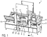
- FIG. 1 shows a packaging machine 1 according to an embodiment.
- the packaging machine 1 comprises a feed device 3 for packaging trays 4 filled with product and to be closed (see FIG Figure 2 ).
- the packaging trays 4 are transferred from the feed device 3 into a sealing station 5 along a production direction P by means of a gripper system.
- the sealing station 5 the packaging trays 4 are closed with a cover film 7.
- the cover film 7 is fed to the sealing station 5 from a supply roll (not shown) which can be attached to a film holder 8 of the packaging machine 1.
- the sealing station 5 comprises a lower tool 9 and an upper tool 11.
- the lower tool 9 and the upper tool 11 are arranged one above the other.
- the sealing station 5 can be moved between an open position and a closed position by means of a drive device 13.
- the lower tool 9 and the upper tool 11 are spaced apart from one another along a vertical direction, so that packaging trays 4 to be closed can be transferred to the lower tool 9 and a corresponding section of the cover film 7 for closing the packaging trays 4 in an area between the lower tool 9 and the upper tool 11 can be brought to lie over the packaging trays 4.
- the sealing station 5 is moved from the open position into a closed position or sealing position in that the drive device 13 moves the lower tool 9 and the upper tool 11 towards one another in the vertical direction. It is conceivable here that both the lower tool 9 and the upper tool 11 are moved, or that only either the lower tool 9 or the upper tool 11 is moved.
- a packaging tray 4 and the cover film 7 are pressed against one another by the lower tool 9 and the upper tool 11 and connected to one another. This is preferably done under the action of heat.
- the lower tool 9 and / or the upper tool 11 can be heated in order to support the sealing process.
- the sealing station 5 is opened again and the closed packaging trays 4 are transferred to a discharge device 15.
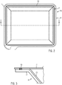
- FIG 2 shows a schematic top view of a finished package 16 which has been closed in the sealing station 5.
- the packaging 16 has the packaging tray 4 and the cover film 7 that closes the packaging tray 4.
- the packaging tray 4 is shown as a rectangular packaging tray. It goes without saying that any other forms of packaging trays 4 are also conceivable.
- the packaging tray 4 comprises a flange 17 which runs around the packaging tray 4.
- the flange 17 provides a connection surface for the connection to the cover film 7.
- the packaging tray 4 and the cover film 7 were connected to one another along a circumferential sealing seam 19 during the sealing process.
- the sealing seam 19 runs along the flange 17 completely around the packaging tray 16.
- Figure 3 shows a partial sectional view through the in Figure 2 shown packaging 16 with respect to the section line II Figure 3
- the packaging tray 4 consists of two material layers arranged one above the other, namely a first material layer 21 and a second material layer 23.
- the first material layer 21 represents a structural layer which defines the shape of the packaging tray 4 and ensures the required rigidity.
- the first material layer 21 can be designed, for example, as a cardboard layer or a paper layer.
- the second material layer 23 is arranged above the first material layer 21 on the side facing the product.
- the second material layer 23 can be designed as a film layer in order to produce an oxygen barrier between the product and the environment.
- the sealing between the cover film 7 and the packaging tray 4 takes place along the sealing seam 19 between the cover film 7 and the second material layer 23 of the packaging tray 4.
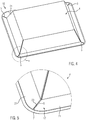
- Figure 4 shows the packaging 16 in a perspective view from below.
- the first material layer 21 of the packaging tray 4 is not continuous.
- the first material layer 21 has slots 5.
- the slots 5 are provided in order to facilitate the folding of the first material layer 21 to form the packaging tray 4.
- the slots 5 also extend beyond the flange 17. In particular, the slots 5 extend essentially radially outward over the flange 17.
- FIG. 4 shows a detailed view of the area F from FIG Figure 4 .
- the second material layer 23 also extends over the slots 5. This ensures that the packaging tray 4 is also tight in the area of the slots 5.
- the second material layer 23 is designed to be continuous across the flange 17.
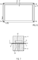
- Figure 6 shows a schematic top view of the lower tool 9 of the sealing station 5.
- the lower tool 9 forms a tray receptacle for receiving the packaging tray 4.
- the body of the packaging tray 4 can be received in a receiving space 27 of the lower tool 9, while the flange 17 of the packaging tray 4 on a lower one Sealing surface 29 of the lower tool 9 rests.
- the lower sealing surface 29 forms a support for the flange 17 of the packaging tray 4.
- FIG. 11 is a sectional view taken along line II-II from FIG Figure 6 during the sealing process, whereby in Figure 7 the packaging tray 4, the cover film 7 and the upper tool 11 are also shown, which in FIG Figure 6 are omitted for the sake of clarity.
- the upper tool 11 comprises a downwardly directed upper sealing surface 31.
- the lower sealing surface 29 and the upper sealing surface 31 are opposite one another.
- the lower sealing surface 29 and the upper sealing surface 31 can each be designed as horizontal, flat surfaces.
- the packaging tray 4 and the cover film 7 are pressed together between the lower sealing surface 29 and the upper sealing surface 31 and are thus connected. This is preferably done with the action of heat in order to facilitate the process.
- the lower tool 9 and / or the upper tool 11 can be heated by means of an integrated heating device 33.
- the packaging tray 4 does not lie against the lower sealing surface 29.
- the lower sealing surface 29 can therefore not function effectively as a counter-pressure element during sealing in the region of the slots 5. Without further measures, this would result in a weak point in the sealing seam 19 with a lower connection strength in the area of the slots 5. In the area of the slots 5, leaks in the connection between the packaging tray 4 and the cover film 7 could occur.
- compressed gas openings 35 are provided.
- the compressed gas openings 35 are in Figure 1 Compressed gas source 37, shown schematically, is connected and configured to allow compressed gas provided by the compressed gas source 37 to escape.
- the sealing station 5 also includes an in Figure 1 schematically illustrated valve 39, which is configured to selectively prevent or release a flow of the pressurized gas from the pressurized gas source 37 to the pressurized gas openings 35.
- the valve 39 is actuated in order to allow pressurized gas to escape through the pressurized gas openings 35 and to locally generate an overpressure in the region of the slits 5.
- this overpressure acts as a counter-pressure element with the upper sealing surface 31 and ensures that the sealing seam 19 is also reliably produced in the area of the slots 5 with a sufficient connection strength and tightness.
- the compressed gas presses the second material layer 23 in the area of the slots 5 from bottom to top against the cover foil 7 and, in the area of the slots 5, together with the upper sealing surface 31, ensures that the packaging tray 4 and the cover foil 7 are pressed together.
- the sequence of a sealing process in the sealing station 5 is described below.
- the sealing process is preferably carried out by means of a control unit 41 (see Figure 1 ) the sealing station 5 can be controlled.
- the control unit 41 can be a separate control unit of the sealing station 5 or functionally part of an overall control unit of the packaging machine 1. It is conceivable, but not necessary, for the control unit 41 to be functionally or physically separate from an overall control unit of the packaging machine 1.
- the drive device 13 is activated by the control unit 41 in order to move the lower tool 9 and the upper tool 11 into the closed position and to press them together.
- the packaging tray 4 and the cover film 7 are pressed against one another along the course of the sealing seam 19 to be created between the lower sealing surface 29 and the upper sealing surface 31. This takes place under the influence of heat.
- the control unit 41 activates the valve 39 to enable the flow of the compressed gas to the compressed gas openings 35.
- a local overpressure is built up in the area of the slots 5 in order to press the second material layer 23 of the packaging tray 4 from below against the cover film 7 in these areas.
- the local overpressure is maintained for a second period of time. After the second period of time has elapsed, the control unit 41 activates the valve 39 in order to prevent the flow of the pressurized gas to the pressurized gas openings 35 again. After stopping the flow of the Pressurized gas to the pressurized gas openings 35, the control unit 41 controls the drive device 13 in order to open the sealing station 5 again.
- the pressurized gas is preferably heated by means of a pressurized gas heating device 43 before it reaches the pressurized gas openings 35 in order to prevent the pressurized gas from cooling the sealing area.
- the pressurized gas heating device 43 is provided on the pressurized gas source 37.
- the local supply of the compressed gas compensates for a locally reduced thickness of the packaging tray 4 due to a local recess in the first material layer 21.
- the invention could, however, also be used to compensate for other local irregularities in the structure of the packaging tray 4 in the area of the sealing seam 19.
- a recess in a lower material layer 21 of the packaging tray 4 instead of a recess in a lower material layer 21 of the packaging tray 4, a recess in an upper material layer 23 of the packaging tray 4 could be compensated for.
- a locally increased compressibility of the packaging tray 4 in the area of the sealing seam 19 could be compensated for.
- the pressurized gas openings 35 are provided in the lower sealing surface 29.
- the local overpressure generated by the supply of pressurized gas can in this case interact as a counter-pressure element with the upper sealing surface 31 during sealing.
- an overpressure could be generated locally which could interact as a counter-pressure element with the lower sealing surface 29 during sealing.
Landscapes
- Engineering & Computer Science (AREA)
- Mechanical Engineering (AREA)
- Physics & Mathematics (AREA)
- Fluid Mechanics (AREA)
- Manufacturing & Machinery (AREA)
- Chemical & Material Sciences (AREA)
- Composite Materials (AREA)
- Closing Of Containers (AREA)
- Vacuum Packaging (AREA)
Abstract
Ein Verfahren zum Verschließen einer Verpackungsschale (4) umfasst das Anordnen einer mit einem zu verpackenden Produkt befüllten Verpackungsschale (4) zwischen einem Unterwerkzeug (9) und einem Oberwerkzeug (11) einer Siegelstation (5), das Positionieren einer Deckelfolie (7) über der Verpackungsschale (4) zwischen dem Unterwerkzeug (9) und dem Oberwerkzeug (11) der Siegelstation (5), und das Zusammenpressen der Deckelfolie (7) und der Verpackungsschale (4) durch eine untere Siegelfläche (29) des Unterwerkzeugs (9) und eine mit der unteren Siegelfläche (29) zusammenwirkende obere Siegelfläche (31) des Oberwerkzeugs (11). Bei dem Zusammenpressen werden die Deckelfolie (7) und die Verpackungsschale (4) entlang einer Siegelnaht (19) miteinander verbunden. Während des Zusammenpressens der Deckelfolie (7) und der Verpackungsschale (4) wird durch Zuführen von Druckgas aus einer Druckgasquelle (37) lokal ein Überdruck erzeugt, welcher als Gegendruck mit der unteren Siegelfläche (29) oder mit der oberen Siegelfläche (31) zusammenwirkt, um die Deckelfolie (7) und die Verpackungsschale (4) zusam menzupressen.
Description
- Die Erfindung betrifft das Ansiegeln einer Deckelfolie an eine Verpackungsschale zum Verschließen der Verpackungsschale.
- Aus der Praxis sind Verpackungsmaschinen mit einer Siegelstation zum Verschließen von mit einem zu verpackenden Produkt befüllten Verpackungsschalen durch Ansiegeln einer Deckelfolie bekannt. Die Siegelstation umfasst für gewöhnlich ein Unterwerkzeug und ein Oberwerkzeug, die zum Verbinden der Verpackungsschale und der Deckelfolie entlang eines Flanschbereichs der Verpackungsschale mittels Wärme und Druckeinwirkung zusammenwirken. Beim Siegelvorgang werden die Verpackungsschale und die Deckelfolie zwischen einer Siegelfläche des Unterwerkzeugs und einer Siegelfläche des Oberwerkzeugs entlang einer umlaufenden Siegelnaht zusammengepresst. Insbesondere beim Verpacken von Lebensmitteln ist darauf zu achten, dass die Siegelnaht tatsächlich dicht ist, um eine entsprechende Haltbarkeit der Produkte gewährleisten zu können.
- Das zuverlässige Erreichen einer dichten Siegelnaht stellt eine besondere Herausforderung dar, wenn die Verpackungsschale in dem für die Siegelnaht vorgesehenen Bereich lokal eine oder mehrere Unregelmäßigkeiten aufweist, wie zum Beispiel eine Erhebung, eine Vertiefung, eine Ausnehmung, einen Schlitz, eine abweichende Materialstärke, oder eine abweichende Materialart. In diesem Fall kann es schwierig sein, beim Siegeln entlang der gesamten Erstreckung der Siegelnaht die Verpackungsschale und die Deckelfolie mit einem ausreichenden Druck aneinander zu pressen.
- Es ist Aufgabe der Erfindung, einen Weg bereitzustellen, wie auch Verpackungsschalen mit einem Siegelbereich, welcher lokal eine oder mehrere Unregelmäßigkeiten aufweist, zuverlässig entlang einer dichten Siegelnaht mit einer Deckelfolie verschlossen werden können.
- Diese Aufgabe wird jeweils gelöst durch ein Verfahren gemäß Anspruch 1, durch eine Siegelstation gemäß Anspruch 10 und durch eine Verwendung gemäß Anspruch 14. Die abhängigen Ansprüche geben vorteilhafte Ausführungsformen der Erfindung an.
- Gemäß einem Aspekt der Erfindung wird ein Verfahren zum Verschließen einer Verpackungsschale bereitgestellt. Das Verfahren umfasst das Anordnen einer mit einem zu verpackenden Produkt befüllten Verpackungsschale zwischen einem Unterwerkzeug und einem Oberwerkzeug einer Siegelstation. Es wird eine Deckelfolie über der Verpackungsschale zwischen dem Unterwerkzeug und dem Oberwerkzeug der Siegelstation positioniert. Durch eine untere Siegelfläche des Unterwerkzeugs und eine mit der unteren Siegelfläche zusammenwirkende obere Siegelfläche des Oberwerkzeugs werden die Deckelfolie und die Verpackungsschale zusammengepresst. Bei dem Zusammenpressen werden die Deckelfolie und die Verpackungsschale entlang einer Siegelnaht miteinander verbunden. Durch Zuführen von Druckgas aus einer Druckgasquelle wird während des Zusammenpressens der Deckelfolie und der Verpackungsschale lokal ein Überdruck erzeugt. Der Überdruck wirkt als Gegendruck mit der unteren Siegelfläche oder mit der oberen Siegelfläche zusammen, um die Deckelfolie und die Verpackungsschale zusammenzupressen.
- Der durch das Zuführen des Druckgases erzeugte Überdruck kann den Siegelvorgang lokal unterstützen. Durch das Erzeugen des lokalen Überdrucks als Gegendruck für die untere Siegelfläche oder die obere Siegelfläche kann die Qualität oder Stärke der Siegelung lokal in einem oder mehreren Bereichen verbessert werden. Insbesondere kann der lokale Überdruck den Siegelvorgang an einer oder mehreren Stellen unterstützen, an denen der durch das Zusammenpressen der Deckelfolie und der Verpackungsschale durch die untere Siegelfläche und die obere Siegelfläche erreichte Siegeldruck alleine nicht ausreicht. Der durch das Zuführen von Druckgas erzeugte Überdruck kann als nicht formgebundenes Gegendruckelement wirken. Das durch den Überdruck bereitgestellte, nicht formgebundene Gegendruckelement kann sich perfekt an die lokale Formgebung der Verpackungsschale anpassen und somit unabhängig von der lokalen Formgebung der Verpackungsschale einen gleichmäßigen Gegendruck für das Siegeln bereitstellen.
- Der Überdruck kann in einem Bereich erzeugt werden, in dem die Verpackungsschale bezüglich ihrer Form oder ihres Materials eine lokale Unregelmäßigkeit aufweist. Zum Beispiel kann der Überdruck in einem Bereich erzeugt werden, in dem die Verpackungsschale eine Erhebung, eine Vertiefung, eine Ausnehmung, einen Schlitz, eine abweichende Materialstärke, oder eine abweichende Materialart aufweist. Der Überdruck kann in einem Bereich erzeugt werden, in dem die Verpackungsschale eine reduzierte Steifigkeit aufweist. Der Überdruck kann in einem Bereich erzeugt werden, in dem erschwerte Bedingungen für das Aufbringen eines ausreichenden Pressdrucks zum Zusammenpressen der Verpackungsschale und der Deckelfolie mittels der unteren Siegelfläche und der oberen Siegelfläche vorliegen.
- Vorzugsweise wird der Überdruck in einem Bereich erzeugt, in dem die Verpackungsschale lokal eine reduzierte Dichte aufweist. Der Überdruck kann dafür sorgen, dass einem durch die untere Siegelfläche oder durch die obere Siegelfläche aufgebrachten Pressdruck ein geeigneter Gegendruck entgegenwirkt, auch wenn dieser aufgrund der lokal reduzierten Dichte der Verpackungsschale in dem betreffenden Bereich nicht, oder nicht vollständig, von der gegenüberliegenden Siegelfläche aufgebracht werden kann. Der Überdruck kann dafür sorgen, dass auch in einem Bereich, in dem die Verpackungsschale eine reduzierte Dicke aufweist, eine ausreichend starke Verbindung zwischen der Verpackungsschale und der Deckelfolie erzeugt wird.
- Wenn die Verpackungsschale zumindest zwei übereinander angeordnete Materiallagen umfasst, wird der Überdruck vorzugsweise in einem Bereich erzeugt, in dem zumindest eine Materiallage der Verpackungsschale ausgespart ist. Im Bereich der ausgesparten Materiallage kann die Verpackungsschale eine lokal reduzierte Dicke und/oder eine reduzierte Steifigkeit aufweisen.
- Zum Beispiel kann die Verpackungsschale eine erste Materiallage und eine zweite Materiallage aufweisen. Die erste Materiallage kann eine höhere Steifigkeit aufweisen als die zweite Materiallage. Die erste Materiallage kann eine Karton- oder Papierlage sein. Die zweite Materiallage kann eine Folienlage sein. Die erste Materiallage und die zweite Materiallage können übereinanderliegend miteinander verbunden sein. Zum Beispiel könnte die erste Materiallage die Form der Verpackungsschale definieren. Die zweite Materiallage könnte im Inneren der Schale auf der ersten Materiallage angebracht sein, um ein zu verpackendes Produkt von der ersten Materiallage zu trennen und/oder um die Verpackungsschale abzudichten. Die zweite Materiallage ist auf der ersten Materiallage vorzugsweise als Sauerstoffbarriereschicht zwischen dem Produkt und der ersten Materiallage ausgebildet.
- Im Fall einer rechteckigen oder polygonalen Verpackungsschale könnte die erste Materiallage, beispielsweise im Bereich der Ecken der Verpackungsschale, schlitzförmige Ausnehmungen umfassen, um ein Falten der Verpackungsschale zu erleichtern. Die zweite Materiallage könnte im Inneren der Verpackungsschale auf der ersten Materiallage angebracht sein und die schlitzförmigen Ausnehmungen überspannen. Beim Ansiegeln der Deckelfolie an die Verpackungsschale könnte in einem oder mehreren Bereichen, in denen die schlitzförmigen Ausnehmungen die Siegelnaht kreuzen, ein Unterdruck erzeugt werden, welcher als Gegendruck mit der unteren Siegelfläche oder mit der oberen Siegelfläche zusammenwirkt um die Deckelfolie und die Verpackungsschale zusammenzupressen. Der Überdruck kann das Auftreten von Undichtigkeiten aufgrund einer mangelhaften Pressdruckübertragung im Bereich der schlitzförmigen Ausnehmungen beim Siegeln verringern.
- Der Überdruck kann an zumindest einer Ecke der Verpackungsschale erzeugt werden. Gemäß einer Ausführungsform wird der Überdruck ausschließlich an einer oder mehreren Ecken der Verpackungsschale erzeugt.
- Der lokale Überdruck kann an einer Stelle erzeugt werden, welche im Verlauf der zu erzeugenden Siegelnaht liegt oder die zu erzeugende Siegelnaht kreuzt.
- In der unteren Siegelfläche oder in der oberen Siegelfläche kann eine Druckgasöffnung vorgesehen sein. Der Überdruck kann durch die Druckgasöffnung bereitgestellt werden. Ein Vorsehen der Druckgasöffnung in der unteren Siegelfläche oder in der oberen Siegelfläche erleichtert einen Druckaufbau während des Siegelns direkt im Bereich der zu erzeugenden Siegelnaht. Wenn die Druckgasöffnung in der unteren Siegelfläche vorgesehen ist, kann der Überdruck als Gegendruck mit der oberen Siegelfläche zusammenwirken. Wenn die Druckgasöffnung in der oberen Siegelfläche vorgesehen ist, kann der Überdruck als Gegendruck mit der unteren Siegelfläche zusammenwirken.
- Vorzugsweise erfolgt das Erzeugen des Überdrucks durch Zuführen des Druckgases erst, nachdem die Deckelfolie und die Verpackungsschale durch die untere Siegelfläche und die obere Siegelfläche zumindest über einen ersten Zeitraum hinweg zusammengepresst wurden. Insbesondere können die Deckelfolie und die Verpackungsschale vor dem Erzeugen des Überdrucks bereits unter Wärmeeinwirkung zusammengepresst worden sein. Wenn bereits vor dem Erzeugen des Überdrucks mit der Siegelung begonnen wurde, kann der Verlauf der Siegelnaht auf der Verpackungsschale und auf der Deckelfolie bereits vor dem Erzeugen des Überdrucks definiert worden sein. Wenn vor dem Erzeugen des Überdrucks bereits zumindest bereichsweise eine Verbindung zwischen der Verpackungsschale und der Deckelfolie besteht, vereinfacht sich das positionsgenaue Erzeugen des Überdrucks. Wenn der lokale Überdruck erst erzeugt wird, wenn mit der Siegelung bereits begonnen wurde, vereinfacht sich das Erzeugen des lokalen Überdrucks, da das Druckgas durch die begonnene Siegelung zumindest teilweise am Entweichen gehindert wird.
- Vorzugsweise wird der Überdruck vor einem Beenden des Zusammenpressens der Deckelfolie und der Verpackungsschale durch die untere Siegelfläche und die obere Siegelfläche zumindest teilweise wieder abgebaut. Hierdurch kann ein Druckverlust beim Öffnen der Siegelstation verringert werden. Außerdem kann verhindert werden, dass die Verpackungsschale bei oder nach dem Öffnen der Siegelstation durch den Überdruck ungewollt bewegt oder verschoben wird.
- Der Überdruck kann ein Druck von zumindest 4 bar, oder zumindest 5 bar, oder zumindest 6 bar sein.
- Vorzugsweise wird das Druckgas vor dem Zuführen aktiv erwärmt. Durch Erwärmen des Druckgases kann vermieden werden, dass die Siegelnaht während des Siegelprozesses durch das Druckgas abgekühlt wird, was die Qualität der Siegelnaht verringern könnte. Das Druckgas kann mittels einer Heizeinrichtung erwärmt werden. Zum Erwärmen des Druckgases kann dieses vor Erreichen der Stelle, an der der Überdruck erzeugt werden soll, durch beheizte Bereiche des Unterwerkzeugs oder des Oberwerkzeugs geleitet werden. Es wäre aber auch denkbar, das Druckgas außerhalb des Oberwerkzeugs und des Unterwerkzeugs oder außerhalb der Siegelstation zu beheizen. Das Druckgas kann durch eine Heizeinrichtung zum Beheizen des Unterwerkzeugs oder durch eine Heizeinrichtung zum Beheizen des Oberwerkzeugs mitbeheizt werden. Es könnte aber auch eine Heizeinrichtung zum Beheizen des Druckgases vorgesehen sein, die unabhängig von einem Beheizen des Unterwerkzeugs und einem Beheizen des Oberwerkzeugs ist. Die Heizeinrichtung könnte beispielsweise eine elektrische Heizeinrichtung sein.
- Gemäß einem weiteren Aspekt betrifft die Erfindung eine Siegelstation. Die Siegelstation umfasst ein Unterwerkzeug mit einer unteren Siegelfläche und ein Oberwerkzeug mit einer oberen Siegelfläche. Das Oberwerkzeug ist oberhalb des Unterwerkzeugs angeordnet. Die Siegelstation umfasst zudem eine Antriebseinrichtung. Die Antriebseinrichtung ist dazu konfiguriert, das Unterwerkzeug und das Oberwerkzeug aufeinander zu zubewegen, sodass eine Verpackungsschale und eine Deckelfolie zum Verschließen der Verpackungsschale zwischen der unteren Siegelfläche und der oberen Siegelfläche aneinandergepresst werden. Zudem umfasst die Siegelstation eine Druckgasquelle. In der unteren Siegelfläche oder in der oberen Siegelfläche ist eine Druckgasöffnung vorgesehen. Die Druckgasöffnung ist dazu konfiguriert, ein von der Druckgasquelle bereitgestelltes Druckgas entweichen zu lassen.
- Durch das Vorsehen der Druckgasöffnung kann im Bereich der Siegelnaht durch Zuführen von Druckgas während des Zusammenpressens der Deckelfolie und der Verpackungsschale lokal ein Überdruck erzeugt werden, welcher als Gegendruck mit der unteren Siegelfläche oder mit der oberen Siegelfläche zusammenwirkt, um die Deckelfolie und die Verpackungsschale zusammenzupressen.
- Vorzugsweise weist die untere Siegelfläche oder die obere Siegelfläche eine Vertiefung auf, in der die Druckgasöffnung angeordnet ist. Durch Vorsehen der Vertiefung kann ein Entweichen des Druckgases erleichtert werden.
- Die Siegelstation kann zudem ein Ventil umfassen, welches dazu konfiguriert ist, einen Fluss des Druckgases von der Druckgasquelle zu der Druckgasöffnung wahlweise zu verhindern oder freizugeben. Die Siegelstation kann zudem eine Steuereinheit umfassen. Die Steuereinheit kann dazu konfiguriert sein, die Antriebseinrichtung zum Aneinanderpressen der Verpackungsschale und der Deckelfolie durch die untere Siegelfläche und die obere Siegelfläche anzusteuern. Die Steuereinheit kann dazu konfiguriert sein, das Ventil zum Freigeben des Flusses des Druckgases zu der Druckgasöffnung anzusteuern, nachdem die Deckelfolie und die Verpackungsschale zumindest für einen vorbestimmten ersten Zeitraum zusammengepresst wurden.
- Die Steuereinheit kann das Ventil zum Verhindern des Flusses des Druckgases von der Druckgasquelle zu der Druckgasöffnung ansteuern, wenn ein auf den ersten Zeitraum folgender, vorbestimmter zweiter Zeitraum abgelaufen ist. Vorzugsweise steuert die Steuereinheit die Antriebseinrichtung erst nach Ablauf des zweiten Zeitraums zum Öffnen der Siegelstation an, wobei beim Öffnen der Siegelstation das Oberwerkzeug und das Unterwerkzeug voneinander entfernt werden.
- Das untere Siegelwerkzeug kann als Schalenaufnahme zur Aufnahme der Verpackungsschale ausgebildet sein. Die untere Siegelfläche kann eine Auflagefläche für einen Flansch der Verpackungsschale bereitstellen.
- Gemäß einem weiteren Aspekt betrifft die Erfindung eine Verwendung von Druckgas zum Bereitstellen von Gegendruck beim Verbinden einer Verpackungsschale mit einer Deckelfolie entlang einer Siegelnaht durch Zusammenpressen der Verpackungsschale und der Deckelfolie durch eine untere Siegelfläche und eine obere Siegelfläche.
- Vorzugsweise wird das Druckgas bezüglich einer Erstreckung der Siegelnaht nur lokal zugeführt, um während des Verbindens der Verpackungsschale und der Deckelfolie eine lokale Irregularität in der Verpackungsschale auszugleichen. Dies ist in dem Sinne zu verstehen, dass der Einfluss der lokalen Irregularität auf den Siegelvorgang ausgeglichen werden soll. Es ist nicht erforderlich, dass die lokale Irregularität selbst durch das Druckgas beseitigt wird.
- Die Erfindung betrifft ein Verfahren zum Verschließen einer Verpackungsschale, eine Siegelstation und eine Verwendung von Druckgas. Merkmale, Eigenschaften und Erläuterungen die in Bezug auf einen dieser Aspekte beschrieben werden, lassen sich jeweils auf die anderen Aspekte übertragen. Insbesondere kann die Siegelstation dazu geeignet, ausgelegt und/oder konfiguriert sein, das Verfahren oder die Verwendung durchzuführen.
- Im Folgenden soll die Erfindung anhand einer Ausführungsform unter Bezugnahme auf die Figuren weiter erläutert werden. Dabei zeigt
- Figur 1
- eine schematische Perspektivansicht einer Verpackungsmaschine mit einer Siegelstation gemäß einer Ausführungsform;
- Figur 2
- eine schematische Draufsicht auf eine mit der Siegelstation verschlossene Verpackung gemäß der Ausführungsform;
- Figur 3
- eine ausschnittsweise schematische Schnittdarstellung der Verpackung, wobei die Schnittlinie in
Figur 2 als I-I eingezeichnet ist; - Figur 4
- die Verpackung aus
Figur 2 in schematischer Perspektivansicht von unten; - Figur 5
- eine Detailansicht von Bereich F aus
Figur 4 ; - Figur 6
- eine schematische Draufsicht auf das Unterwerkzeug der Siegelstation gemäß der Ausführungsform; und
- Figur 7
- eine schematische Schnittdarstellung während des Siegelvorgangs, wobei die Lage des Schnitts in
Figur 6 mit II-II gekennzeichnet ist. -
Figur 1 zeigt eine Verpackungsmaschine 1 gemäß einer Ausführungsform. Die Verpackungsmaschine 1 umfasst eine Zuführvorrichtung 3 für mit Produkt befüllte, zu verschließende Verpackungsschalen 4 (sieheFigur 2 ). Die Verpackungsschalen 4 werden von der Zuführvorrichtung 3 entlang einer Produktionsrichtung P mittels eines Greifersystems in eine Siegelstation 5 umgesetzt. In der Siegelstation 5 werden die Verpackungsschalen 4 mit einer Deckelfolie 7 verschlossen. Die Deckelfolie 7 wird der Siegelstation 5 von einer Vorratsrolle (nicht dargestellt) zugeführt, welche an einer Folienaufnahme 8 der Verpackungsmaschine 1 anbringbar ist. Die Siegelstation 5 umfasst ein Unterwerkzeug 9 und ein Oberwerkzeug 11. Das Unterwerkzeug 9 und das Oberwerkzeug 11 sind übereinander angeordnet. Mittels einer Antriebseinrichtung 13 kann die Siegelstation 5 zwischen einer geöffneten Stellung und einer geschlossenen Stellung verfahren werden. In der geöffneten Stellung sind das Unterwerkzeug 9 und das Oberwerkzeug 11 entlang einer vertikalen Richtung voneinander beabstandet, sodass zu verschließende Verpackungsschalen 4 auf das Unterwerkzeug 9 umgesetzt werden können und ein entsprechender Abschnitt der Deckelfolie 7 zum Verschließen der Verpackungsschalen 4 in einen Bereich zwischen dem Unterwerkzeug 9 und dem Oberwerkzeug 11 verbracht werden kann, um über der Verpackungsschalen 4 zu liegen. Aus der geöffneten Stellung heraus wird die Siegelstation 5 in eine geschlossene Stellung oder Siegelstellung verbracht, indem die Antriebseinrichtung 13 das Unterwerkzeug 9 und das Oberwerkzeug 11 entlang der vertikalen Richtung aufeinander zu bewegt. Hierbei ist es denkbar, dass sowohl das Unterwerkzeug 9 als auch das Oberwerkzeug 11 bewegt werden, oder dass nur entweder das Unterwerkzeug 9 oder das Oberwerkzeug 11 bewegt wird. - Bei einem Siegelvorgang werden eine Verpackungsschale 4 und die Deckelfolie 7 durch das Unterwerkzeug 9 und das Oberwerkzeug 11 aneinandergepresst und miteinander verbunden. Dies geschieht vorzugsweise unter Wärmeeinwirkung. Zum Beispiel kann das Unterwerkzeug 9 und/oder das Oberwerkzeug 11 beheizt werden, um den Siegelvorgang zu unterstützen.
- Nach erfolgtem Siegeln wird die Siegelstation 5 wieder geöffnet und die verschlossenen Verpackungsschalen 4 werden an eine Abführvorrichtung 15 übergeben.
-
Figur 2 zeigt eine schematische Draufsicht auf eine fertiggestellte Verpackung 16, welche in der Siegelstation 5 verschlossen wurde. Die Verpackung 16 weist die Verpackungsschale 4 sowie die die Verpackungsschale 4 verschließende Deckelfolie 7 auf. Die Verpackungsschale 4 ist als rechteckige Verpackungsschale gezeigt. Es versteht sich, dass auch beliebige andere Formen von Verpackungsschalen 4 denkbar sind. Die Verpackungsschale 4 umfasst einen Flansch 17, welcher die Verpackungsschale 4 umläuft. Der Flansch 17 stellt eine Verbindungsfläche für die Verbindung mit der Deckelfolie 7 bereit. Wie inFigur 2 dargestellt, wurden die Verpackungsschale 4 und die Deckelfolie 7 während des Siegelprozesses entlang einer umlaufenden Siegelnaht 19 miteinander verbunden. Die Siegelnaht 19 verläuft entlang des Flansches 17 vollständig um die Verpackungsschale 16 herum. -
Figur 3 zeigt eine ausschnittsweise Schnittansicht durch die inFigur 2 dargestellte Verpackung 16 bezüglich der Schnittlinie I-I. AusFigur 3 ist ersichtlich, dass die Verpackungsschale 4 aus zwei übereinander angeordneten Materiallagen besteht, nämlich einer ersten Materiallage 21 und einer zweiten Materiallage 23. Die erste Materiallage 21 stellt eine Strukturschicht dar, welche die Form der Verpackungsschale 4 vorgibt und für die erforderliche Steifigkeit sorgt. Die erste Materiallage 21 kann beispielsweise als Kartonlage oder Papierlage ausgebildet sein. Die zweite Materiallage 23 ist auf der dem Produkt zugewandten Seite über der ersten Materiallage 21 angeordnet. Die zweite Materiallage 23 kann als Folienlage ausgebildet sein, um eine Sauerstoffbarriere zwischen dem Produkt und der Umgebung herzustellen. Die Siegelung zwischen der Deckelfolie 7 und der Verpackungsschale 4 erfolgt in der gezeigten Ausführungsform entlang der Siegelnaht 19 zwischen der Deckelfolie 7 und der zweiten Materiallage 23 der Verpackungsschale 4. -
Figur 4 zeigt die Verpackung 16 in einer Perspektivansicht von unten. InFigur 4 ist ersichtlich, dass die erste Materiallage 21 der Verpackungsschale 4 nicht durchgängig ausgebildet ist. Im Bereich der Ecken der Verpackungsschale 4 weist die erste Materiallage 21 Schlitze 5 auf. Die Schlitze 5 sind vorgesehen, um das Falten der ersten Materiallage 21 zu der Verpackungsschale 4 zu erleichtern. Die Schlitze 5 erstrecken sich auch über den Flansch 17 hinweg. Insbesondere erstrecken sich die Schlitze 5 im Wesentlichen radial nach außen über den Flansch 17 hinweg. -
Figur 5 zeigt eine Detailansicht des Bereichs F ausFigur 4 . InFigur 5 ist ersichtlich, dass sich die zweite Materiallage 23 auch über die Schlitze 5 hinweg erstreckt. Hierdurch wird sichergestellt, dass die Verpackungsschale 4 auch im Bereich der Schlitze 5 dicht ist. Insbesondere ist die zweite Materiallage 23 über den Flansch 17 hinweg durchgängig ausgebildet. -
Figur 6 zeigt eine schematische Draufsicht auf das Unterwerkzeug 9 der Siegelstation 5. Das Unterwerkzeug 9 bildet eine Schalenaufnahme zur Aufnahme der Verpackungsschale 4. Der Körper der Verpackungsschale 4 kann in einem Aufnahmeraum 27 des Unterwerkzeugs 9 aufgenommen sein, während der Flansch 17 der Verpackungsschale 4 auf einer unteren Siegelfläche 29 des Unterwerkzeugs 9 aufliegt. Die untere Siegelfläche 29 bildet eine Auflage für den Flansch 17 der Verpackungsschale 4. -
Figur 7 ist eine Schnittdarstellung bezüglich der Schnittlinie II-II ausFigur 6 während des Siegelprozesses, wobei inFigur 7 auch die Verpackungsschale 4, die Deckelfolie 7 und das Oberwerkzeug 11 dargestellt sind, welche inFigur 6 der Übersichtlichkeit halber weggelassen sind. Das Oberwerkzeug 11 umfasst eine nach unten gerichtete obere Siegelfläche 31. Die untere Siegelfläche 29 und die obere Siegelfläche 31 liegen sich gegenüber. Die untere Siegelfläche 29 und die obere Siegelfläche 31 können jeweils als horizontale, ebene Flächen ausgebildet sein. Während des Siegelvorgangs werden die Verpackungsschale 4 und die Deckelfolie 7 zwischen der unteren Siegelfläche 29 und der oberen Siegelfläche 31 zusammengepresst und somit verbunden. Vorzugsweise erfolgt dies unter Wärmeeinwirkung, um den Vorgang zu erleichtern. Zum Beispiel kann das Unterwerkzeug 9 und/oder das Oberwerkzeug 11 mittels einer integrierten Heizeinrichtung 33 beheizt werden. - In den Bereichen des Flansches 17, in denen die Verpackungsschale 4 sowohl durch die erste Materiallage 21 als auch durch die darüber angeordnete zweite Materiallage 23 gebildet ist, also überall außer im Bereich der Schlitze 5, liegt beim Siegeln ein direkter Kontakt zwischen der unteren Siegelfläche 29 und dem Flansch 17 und ein direkter Kontakt zwischen der oberen Siegelfläche 31 und der Deckelfolie 7 vor. Beim Aneinanderpressen der Verpackungsschale 4 und der Deckelfolie 7 wirkt in diesen Bereichen die untere Siegelfläche 29 als Gegendruckelement für die obere Siegelfläche 31 und wirkt die obere Siegelfläche 31 als Gegendruckelement für die untere Siegelfläche 29. Im Bereich der Schlitze 5 ist dies aufgrund der reduzierten Dicke der Verpackungsschale 4 (wegen des lokalen Fehlens der ersten Materiallage 21) nicht der Fall. Im Bereich der Schlitze 5 liegt die Verpackungsschale 4 nicht an der unteren Siegelfläche 29 an. Die untere Siegelfläche 29 kann beim Siegeln im Bereich der Schlitze 5 somit nicht wirksam als Gegendruckelement fungieren. Ohne weitere Maßnahmen hätte dies eine Schwachstelle der Siegelnaht 19 mit einer geringeren Verbindungsstärke im Bereich der Schlitze 5 zur Folge. Im Bereich der Schlitze 5 könnten Undichtigkeiten der Verbindung zwischen der Verpackungsschale 4 und der Deckelfolie 7 auftreten.
- Um dieser Problematik zu begegnen, sind in der unteren Siegelfläche 29 im Bereich der Ecken, an den Stellen, an denen die Schlitze 5 der Verpackungsschale 4 während des Siegelvorgangs liegen, Druckgasöffnungen 35 vorgesehen. Die Druckgasöffnungen 35 sind mit einer in
Figur 1 schematisch dargestellten Druckgasquelle 37 verbunden und dazu konfiguriert, von der Druckgasquelle 37 bereitgestelltes Druckgas entweichen zu lassen. Die Siegelstation 5 umfasst zudem ein inFigur 1 schematisch dargestelltes Ventil 39, welches dazu konfiguriert ist, einen Fluss des Druckgases von der Druckgasquelle 37 zu den Druckgasöffnungen 35 wahlweise zu verhindern oder freizugeben. Während des Siegelvorgangs wird das Ventil 39 betätigt, um Druckgas durch die Druckgasöffnungen 35 entweichen zu lassen und im Bereich der Schlitze 5 lokal einen Überdruck zu erzeugen. Dieser Überdruck wirkt beim Siegeln im Bereich der Schlitze 5 als Gegendruckelement mit der oberen Siegelfläche 31 zusammen und sorgt dafür, dass die Siegelnaht 19 auch im Bereich der Schlitze 5 zuverlässig mit einer ausreichenden Verbindungsstärke und Dichtigkeit hergestellt wird. Das Druckgas drückt in der dargestellten Ausführungsform die zweite Materiallage 23 im Bereich der Schlitze 5 von unten nach oben gegen die Deckelfolie 7 und sorgt im Bereich der Schlitze 5 zusammen mit der oberen Siegelfläche 31 für ein Zusammendrücken der Verpackungsschale 4 und der Deckelfolie 7. - Im Folgenden wird der Ablauf eines Siegelvorgangs in der Siegelstation 5 beschrieben. Der Siegelvorgang wird vorzugsweise mittels einer Steuereinheit 41 (siehe
Figur 1 ) der Siegelstation 5 gesteuert werden. Die Steuereinheit 41 kann eine separate Steuereinheit der Siegelstation 5 sein oder funktionsmäßig Teil einer Gesamtsteuereinheit der Verpackungsmaschine 1 sein. Es ist denkbar, aber nicht erforderlich, dass die Steuereinheit 41 funktional oder physisch von einer Gesamtsteuereinheit der Verpackungsmaschine 1 getrennt ist. - Zu Beginn des Siegelvorgangs wird die Antriebseinrichtung 13 von der Steuereinheit 41 angesteuert, um das Unterwerkzeug 9 und das Oberwerkzeug 11 in die geschlossene Stellung zu verfahren und aneinanderzupressen. Hierbei werden die Verpackungsschale 4 und die Deckelfolie 7 entlang des Verlaufs der zu erstellenden Siegelnaht 19 zwischen der unteren Siegelfläche 29 und der oberen Siegelfläche 31 aneinandergepresst. Dies erfolgt unter Wärmeeinwirkung. Nachdem die Verpackungsschale 4 und die Deckelfolie 7 auf diese Art und Weise über einen ersten Zeitraum hinweg zusammengepresst wurden, steuert die Steuereinheit 41 das Ventil 39 zum Freigeben des Flusses des Druckgases zu den Druckgasöffnungen 35 an. Im Bereich der Schlitze 5 wird, wie beschrieben, ein lokaler Überdruck aufgebaut, um in diesen Bereichen die zweite Materiallage 23 der Verpackungsschale 4 von unten gegen die Deckelfolie 7 zu drücken. Der lokale Überdruck wird über einen zweiten Zeitraum hinweg aufrechterhalten. Nach Ablauf des zweiten Zeitraums steuert die Steuereinheit 41 das Ventil 39 an, um den Fluss des Druckgases zu den Druckgasöffnungen 35 wieder zu unterbinden. Nach dem Unterbinden des Flusses des Druckgases zu den Druckgasöffnungen 35 steuert die Steuereinheit 41 die Antriebseinrichtung 13 an, um die Siegelstation 5 wieder zu öffnen.
- Vorzugsweise wird das Druckgas vor Erreichen der Druckgasöffnungen 35 mittels einer Druckgas-Heizeinrichtung 43 beheizt, um eine Abkühlung des Siegelbereichs durch das Druckgas zu vermeiden. In der dargestellten Ausführungsform ist die Druckgas-Heizeinrichtung 43 an der Druckgasquelle 37 vorgesehen.
- In der dargestellten Ausführungsform wird durch das lokale Zuführen des Druckgases eine aufgrund einer lokalen Aussparung der ersten Materiallage 21 lokal verminderte Dicke der Verpackungsschale 4 ausgeglichen. Die Erfindung könnte aber auch zum Ausgleich anderer lokaler Irregularitäten im Aufbau der Verpackungsschale 4 im Bereich der Siegelnaht 19 angewandt werden. Zum Beispiel könnte anstatt einer Aussparung in einer unteren Materiallage 21 der Verpackungsschale 4 eine Aussparung in einer oberen Materiallage 23 der Verpackungsschale 4 ausgeglichen werden. Es wäre zum Beispiel auch denkbar, durch das lokale Vorsehen der Druckgas während des Siegelns Irregularitäten auszugleichen, welche durch lokale Materialunterschiede (mit oder ohne Dickenunterschiede) der Verpackungsschale 4 im Bereich der Siegelnaht 19 gegeben sind. Beispielsweise könnte eine lokal erhöhte Kompressibilität der Verpackungsschale 4 im Bereich der Siegelnaht 19 ausgeglichen werden.
- In der gezeigten Ausführungsform sind die Druckgasöffnungen 35 in der unteren Siegelfläche 29 vorgesehen. Der durch die Druckgaszufuhr erzeugte lokale Überdruck kann in diesem Fall beim Siegeln als Gegendruckelement mit der oberen Siegelfläche 31 zusammenwirken. Je nach Anwendung wäre es alternativ oder zusätzlich auch denkbar, entsprechende Druckgasöffnungen 35 in der oberen Siegelfläche 31 vorzusehen. Durch Zufuhr von Druckgas durch diese Druckgasöffnungen 35 könnte lokal ein Überdruck erzeugt werden, welcher beim Siegeln als Gegendruckelement mit der unteren Siegelfläche 29 zusammenwirken könnte.
Claims (15)
- Verfahren zum Verschließen einer Verpackungsschale (4), umfassend:Anordnen einer mit einem zu verpackenden Produkt befüllten Verpackungsschale (4) zwischen einem Unterwerkzeug (9) und einem Oberwerkzeug (11) einer Siegelstation (5);Positionieren einer Deckelfolie (7) über der Verpackungsschale (4) zwischen dem Unterwerkzeug (9) und dem Oberwerkzeug (11) der Siegelstation (5); undZusammenpressen der Deckelfolie (7) und der Verpackungsschale (4) durch eine untere Siegelfläche (29) des Unterwerkzeugs (9) und eine mit der unteren Siegelfläche (29) zusammenwirkende obere Siegelfläche (31) des Oberwerkzeugs (11), wobei bei dem Zusammenpressen die Deckelfolie (7) und die Verpackungsschale (4) entlang einer Siegelnaht (19) miteinander verbunden werden,wobei während des Zusammenpressens der Deckelfolie (7) und der Verpackungsschale (4) durch Zuführen von Druckgas aus einer Druckgasquelle (37) lokal ein Überdruck erzeugt wird, welcher als Gegendruck mit der unteren Siegelfläche (29) oder mit der oberen Siegelfläche (31) zusammenwirkt, um die Deckelfolie (7) und die Verpackungsschale (4) zusammenzupressen.
- Verfahren nach Anspruch 1, wobei der Überdruck in einem Bereich erzeugt wird, in dem die Verpackungsschale (4) lokal eine reduzierte Dicke aufweist.
- Verfahren nach Anspruch 1 oder 2, wobei die Verpackungsschale (4) zumindest zwei übereinander angeordnete Materiallagen (21, 23) umfasst, wobei der Überdruck in einem Bereich erzeugt wird, in dem zumindest eine Materiallage (21, 23) der Verpackungsschale (4) ausgespart ist.
- Verfahren nach einem der vorangehenden Ansprüche, wobei der Überdruck an zumindest einer Ecke der Verpackungsschale (4) erzeugt wird.
- Verfahren nach einem der vorangehenden Ansprüche, wobei in der unteren Siegelfläche (29) oder in der oberen Siegelfläche (31) eine Druckgasöffnung (35) vorgesehen ist und der Überdruck durch die Druckgasöffnung (35) bereitgestellt wird.
- Verfahren nach einem der vorangehenden Ansprüche, wobei das Erzeugen des Überdrucks durch Zuführen des Druckgases erst erfolgt, nachdem die Deckelfolie (7) und die Verpackungsschale (4) zumindest für einen ersten Zeitraum durch die untere Siegelfläche (29) und die obere Siegelfläche (31) zusammengepresst wurden.
- Verfahren nach einem der vorangehenden Ansprüche, wobei der Überdruck vor einem Beenden des Zusammenpressens der Deckelfolie (7) und der Verpackungsschale (4) durch die untere Siegelfläche (29) und die obere Siegelfläche (31) wieder abgebaut wird.
- Verfahren nach einem der vorangehenden Ansprüche, wobei der Überdruck ein Druck von zumindest 4 bar, oder zumindest 5 bar, oder zumindest 6 bar ist.
- Verfahren nach einem der vorangehenden Ansprüche, wobei das Druckgas vor dem Zuführen aktiv erwärmt wird.
- Siegelstation (5), umfassend:ein Unterwerkzeug (9) mit einer unteren Siegelfläche (29);ein oberhalb des Unterwerkzeugs (9) angeordnetes Oberwerkzeug (11) mit einer oberen Siegelfläche (31);eine Antriebseinrichtung (13), welche dazu konfiguriert ist, das Unterwerkzeug (9) und das Oberwerkzeug (11) aufeinander zu zubewegen, so dass eine Verpackungsschale (4) und eine Deckelfolie (7) zum Verschließen der Verpackungsschale (4) zwischen der unteren Siegelfläche (29) und der oberen Siegelfläche (31) aneinandergepresst werden; undeine Druckgasquelle (37),wobei in der unteren Siegelfläche (29) oder in der oberen Siegelfläche (31) eine Druckgasöffnung (35) vorgesehen ist, welche dazu konfiguriert ist, ein von der Druckgasquelle (37) bereitgestelltes Druckgas entweichen zu lassen.
- Siegelstation nach Anspruch 10, wobei die untere Siegelfläche (29) oder die obere Siegelfläche (31) eine Vertiefung aufweist, und wobei die Druckgasöffnung (35) in der Vertiefung angeordnet ist.
- Siegelstation nach Anspruch 10 oder 11, wobei
die Siegelstation (5) zudem ein Ventil (39) umfasst, welches dazu konfiguriert ist, einen Fluss des Druckgases von der Druckgasquelle (37) zu der Druckgasöffnung (35) wahlweise zu verhindern oder freizugeben, und
die Siegelstation (5) zudem eine Steuereinheit (41) umfasst, welche dazu konfiguriert ist, die Antriebseinrichtung (13) zum Aneinanderpressen der Verpackungsschale (4) und der Deckelfolie (7) durch die untere Siegelfläche (29) und die obere Siegelfläche (31) anzusteuern und das Ventil (39) zum Freigeben des Flusses des Druckgases zu der Druckgasöffnung (35) anzusteuern, nachdem die Deckelfolie (7) und die Verpackungsschale (4) zumindest für einen vorbestimmten ersten Zeitraum zusammengepresst wurden. - Siegelstation nach einem der Ansprüche 10 bis 12, wobei das untere Siegelwerkzeug (9) als Schalenaufnahme zur Aufnahme der Verpackungsschale (4) ausgebildet ist, wobei die untere Siegelfläche (29) eine Auflagefläche für einen Flansch (17) der Verpackungsschale (4) bereitstellt.
- Verwendung von Druckgas zum Bereitstellen von Gegendruck beim Verbinden einer Verpackungsschale (4) mit einer Deckelfolie (7) entlang einer Siegelnaht (19) durch Zusammenpressen der Verpackungsschale (4) und der Deckelfolie (7) durch eine untere Siegelfläche (29) und eine obere Siegelfläche (31).
- Verwendung nach Anspruch 14, wobei das Druckgas bezüglich einer Erstreckung der Siegelnaht (19) nur lokal zugeführt wird, um während des Verbindens eine lokale Irregularität in der Verpackungsschale (4) auszugleichen.
Applications Claiming Priority (1)
| Application Number | Priority Date | Filing Date | Title |
|---|---|---|---|
| DE102020207551.4A DE102020207551A1 (de) | 2020-06-18 | 2020-06-18 | Siegeln mit Druckluftunterstützung |
Publications (1)
| Publication Number | Publication Date |
|---|---|
| EP3925764A1 true EP3925764A1 (de) | 2021-12-22 |
Family
ID=76355341
Family Applications (1)
| Application Number | Title | Priority Date | Filing Date |
|---|---|---|---|
| EP21178431.9A Withdrawn EP3925764A1 (de) | 2020-06-18 | 2021-06-09 | Siegeln mit druckluftunterstützung |
Country Status (3)
| Country | Link |
|---|---|
| US (1) | US11649082B2 (de) |
| EP (1) | EP3925764A1 (de) |
| DE (1) | DE102020207551A1 (de) |
Families Citing this family (1)
| Publication number | Priority date | Publication date | Assignee | Title |
|---|---|---|---|---|
| DE102021110382A1 (de) * | 2021-04-23 | 2022-10-27 | Multivac Sepp Haggenmüller Se & Co. Kg | Siegelstation mit einer Produktschutzplatte |
Citations (3)
| Publication number | Priority date | Publication date | Assignee | Title |
|---|---|---|---|---|
| US3962844A (en) * | 1974-08-21 | 1976-06-15 | International Paper Company | Process for forming and applying a hermetic, heat sealed closure |
| US5049720A (en) * | 1990-08-24 | 1991-09-17 | Fmc Corporation | Laser welding apparatus with sky window |
| EP0564695A1 (de) * | 1992-04-04 | 1993-10-13 | Tetra Laval Convenience Food GmbH & Co. KG | Verfahren und Vorrichtung zur Herstellung einer wiederverschliessbaren Verpackung |
Family Cites Families (14)
| Publication number | Priority date | Publication date | Assignee | Title |
|---|---|---|---|---|
| US3536567A (en) * | 1967-08-14 | 1970-10-27 | Halm Instrument Co | Heat sealing and cooling means |
| US3793115A (en) * | 1971-11-22 | 1974-02-19 | T Jindra | Apparatus for shaping and welding plastic sheet material for packaging articles |
| FR2600995B1 (fr) * | 1986-07-02 | 1988-10-28 | Erca Holding | Procede et dispositif de fabrication et de mise en place d'un couvercle thermoplastique a contre-depouille sur un recipient et recipient muni d'un tel couvercle |
| US4991375A (en) * | 1988-11-14 | 1991-02-12 | Raque Food Systems, Inc. | Heat seal carrier assembly |
| US5156329A (en) * | 1989-04-05 | 1992-10-20 | American National Can Company | Seal testable container structure |
| DE3925746C2 (de) * | 1989-08-03 | 1994-06-23 | Multivac Haggenmueller Kg | Verfahren und Vorrichtung zum Herstellen einer wiederverschließbaren Packung |
| JPH0737253B2 (ja) * | 1989-12-27 | 1995-04-26 | 株式会社フジキカイ | フィルムのヒートシール装置 |
| CA2079043A1 (en) * | 1992-04-04 | 1993-10-05 | Alfred Schmeck | Method and apparatus for the manufacture of a resealable package |
| NL9202176A (nl) * | 1992-08-04 | 1994-03-01 | Stork Titan Bv | Verpakken van voedingswaar. |
| US6625955B2 (en) | 2000-06-28 | 2003-09-30 | Aylward Enterprises, Inc. | Methods for forming product package with recloseable locking mechanism |
| DE10149136A1 (de) | 2001-10-05 | 2003-04-17 | Bosch Gmbh Robert | Vorrichtung und Verfahren zum Herstellen und Verschließen von aus wenigstens einer heißsiegelfähigen Packstoffbahn hergestellten Packung |
| DE102006020360A1 (de) * | 2006-02-09 | 2007-08-16 | Cfs Germany Gmbh | Siegelstation einer Verpackungsmaschine |
| EP2284085B1 (de) | 2009-08-11 | 2013-03-13 | Sauerlandfrische Dornseifer GmbH & Co. KG | Abgepacktes Fertiggericht und Verfahren zu seiner Herstellung |
| DE102012006696A1 (de) * | 2012-03-30 | 2013-10-02 | Multivac Sepp Haggenmüller Gmbh & Co. Kg | Verpackungsmaschine mit einer Siegelvorrichtung |
-
2020
- 2020-06-18 DE DE102020207551.4A patent/DE102020207551A1/de active Pending
-
2021
- 2021-06-09 EP EP21178431.9A patent/EP3925764A1/de not_active Withdrawn
- 2021-06-18 US US17/351,831 patent/US11649082B2/en active Active
Patent Citations (3)
| Publication number | Priority date | Publication date | Assignee | Title |
|---|---|---|---|---|
| US3962844A (en) * | 1974-08-21 | 1976-06-15 | International Paper Company | Process for forming and applying a hermetic, heat sealed closure |
| US5049720A (en) * | 1990-08-24 | 1991-09-17 | Fmc Corporation | Laser welding apparatus with sky window |
| EP0564695A1 (de) * | 1992-04-04 | 1993-10-13 | Tetra Laval Convenience Food GmbH & Co. KG | Verfahren und Vorrichtung zur Herstellung einer wiederverschliessbaren Verpackung |
Also Published As
| Publication number | Publication date |
|---|---|
| DE102020207551A1 (de) | 2021-12-23 |
| US11649082B2 (en) | 2023-05-16 |
| US20210394943A1 (en) | 2021-12-23 |
Similar Documents
| Publication | Publication Date | Title |
|---|---|---|
| DE3941183C2 (de) | ||
| EP2251265B1 (de) | Verpackungsmaschine | |
| DE3739432C2 (de) | ||
| EP0076979B1 (de) | Packung für fliessfähige Füllgüter mit Verstärkungsstreifen | |
| EP0710605A1 (de) | Verfahren und Vorrichtung zum Maximieren der Taktgeschwindigkeit einer Vakuumverpackungsmaschine | |
| EP1908689A2 (de) | Abdichtleiste für kontrollierte Gaszufuhr in die Verpackungen | |
| EP2251264A1 (de) | Verpackungsmaschine und Verfahren zum Verschließen von Behältern mit Deckeln | |
| DE102006020361A1 (de) | Verpackungsmaschine für die Herstellung einer Verpackung mit einem Rücksprung in dem Verpackungsmuldenrand | |
| EP2644516A1 (de) | Verpackungsmaschine mit einer Siegelvorrichtung | |
| DE1411657A1 (de) | Versiegelbarer Faltkarton | |
| DE102020207551A1 (de) | Siegeln mit Druckluftunterstützung | |
| CH700772A2 (de) | Arbeitsstation einer Blisterverpackungsmaschine. | |
| DE3404451A1 (de) | Verpackungsmaschine mit einer versiegelungsstation | |
| EP3880559A2 (de) | Doppelpackung mit unterschiedlicher begasung | |
| EP3405399A2 (de) | Siegelwerkzeug, verpackungmachine und verfahren zur herstellung eine skinverpackung | |
| WO2011134591A2 (de) | Verpackungsmaschine mit einem mittel zur befestigung einer einlage an einem verpackungsmuldenstrukturelement | |
| EP4523893A1 (de) | Siegeleinrichtung mit angetriebener halteeinrichtung | |
| EP3294636A1 (de) | Verpackungsmaschine mit einer hubvorrichtung | |
| EP4368366B1 (de) | Tiefziehvorrichtung, verpackungsmaschine mit einer tiefziehvorrichtung und verfahren zum betrieb der tiefziehvorrichtung | |
| EP1584448A1 (de) | Siegeleinheit zum Aufbringen einer Kunststoffolie auf ein Substratmaterial | |
| EP2380726B1 (de) | Verpackungsmaschine mit oszillierendem Siegelwerkzeug | |
| EP3733528B1 (de) | Siegelwerkzeug und verfahren zum versiegeln von schalen | |
| DE2337730A1 (de) | Verpackungsmaschine | |
| EP4155056A1 (de) | Formstation für eine tiefziehverpackungsmaschine, tiefziehverpackungsmaschine, deren verwendung sowie verfahren zum tiefziehen einer kunststofffolie | |
| DE102021109913A1 (de) | Verschließen einer Verpackungsschale mit mehreren Materialschichten |
Legal Events
| Date | Code | Title | Description |
|---|---|---|---|
| PUAI | Public reference made under article 153(3) epc to a published international application that has entered the european phase |
Free format text: ORIGINAL CODE: 0009012 |
|
| STAA | Information on the status of an ep patent application or granted ep patent |
Free format text: STATUS: THE APPLICATION HAS BEEN PUBLISHED |
|
| AK | Designated contracting states |
Kind code of ref document: A1 Designated state(s): AL AT BE BG CH CY CZ DE DK EE ES FI FR GB GR HR HU IE IS IT LI LT LU LV MC MK MT NL NO PL PT RO RS SE SI SK SM TR |
|
| B565 | Issuance of search results under rule 164(2) epc |
Effective date: 20211122 |
|
| STAA | Information on the status of an ep patent application or granted ep patent |
Free format text: STATUS: THE APPLICATION IS DEEMED TO BE WITHDRAWN |
|
| 18D | Application deemed to be withdrawn |
Effective date: 20220623 |