EP3924614B1 - Ventilvorrichtung - Google Patents
Ventilvorrichtung Download PDFInfo
- Publication number
- EP3924614B1 EP3924614B1 EP19705484.4A EP19705484A EP3924614B1 EP 3924614 B1 EP3924614 B1 EP 3924614B1 EP 19705484 A EP19705484 A EP 19705484A EP 3924614 B1 EP3924614 B1 EP 3924614B1
- Authority
- EP
- European Patent Office
- Prior art keywords
- valve
- valve device
- valve guide
- housing
- conductor path
- Prior art date
- Legal status (The legal status is an assumption and is not a legal conclusion. Google has not performed a legal analysis and makes no representation as to the accuracy of the status listed.)
- Active
Links
Images


Classifications
-
- F—MECHANICAL ENGINEERING; LIGHTING; HEATING; WEAPONS; BLASTING
- F02—COMBUSTION ENGINES; HOT-GAS OR COMBUSTION-PRODUCT ENGINE PLANTS
- F02M—SUPPLYING COMBUSTION ENGINES IN GENERAL WITH COMBUSTIBLE MIXTURES OR CONSTITUENTS THEREOF
- F02M26/00—Engine-pertinent apparatus for adding exhaust gases to combustion-air, main fuel or fuel-air mixture, e.g. by exhaust gas recirculation [EGR] systems
- F02M26/65—Constructional details of EGR valves
-
- F—MECHANICAL ENGINEERING; LIGHTING; HEATING; WEAPONS; BLASTING
- F02—COMBUSTION ENGINES; HOT-GAS OR COMBUSTION-PRODUCT ENGINE PLANTS
- F02M—SUPPLYING COMBUSTION ENGINES IN GENERAL WITH COMBUSTIBLE MIXTURES OR CONSTITUENTS THEREOF
- F02M26/00—Engine-pertinent apparatus for adding exhaust gases to combustion-air, main fuel or fuel-air mixture, e.g. by exhaust gas recirculation [EGR] systems
- F02M26/65—Constructional details of EGR valves
- F02M26/72—Housings
- F02M26/73—Housings with means for heating or cooling the EGR valve
-
- F—MECHANICAL ENGINEERING; LIGHTING; HEATING; WEAPONS; BLASTING
- F16—ENGINEERING ELEMENTS AND UNITS; GENERAL MEASURES FOR PRODUCING AND MAINTAINING EFFECTIVE FUNCTIONING OF MACHINES OR INSTALLATIONS; THERMAL INSULATION IN GENERAL
- F16K—VALVES; TAPS; COCKS; ACTUATING-FLOATS; DEVICES FOR VENTING OR AERATING
- F16K1/00—Lift valves or globe valves, i.e. cut-off apparatus with closure members having at least a component of their opening and closing motion perpendicular to the closing faces
-
- F—MECHANICAL ENGINEERING; LIGHTING; HEATING; WEAPONS; BLASTING
- F16—ENGINEERING ELEMENTS AND UNITS; GENERAL MEASURES FOR PRODUCING AND MAINTAINING EFFECTIVE FUNCTIONING OF MACHINES OR INSTALLATIONS; THERMAL INSULATION IN GENERAL
- F16K—VALVES; TAPS; COCKS; ACTUATING-FLOATS; DEVICES FOR VENTING OR AERATING
- F16K31/00—Actuating devices; Operating means; Releasing devices
- F16K31/44—Mechanical actuating means
- F16K31/52—Mechanical actuating means with crank, eccentric, or cam
-
- F—MECHANICAL ENGINEERING; LIGHTING; HEATING; WEAPONS; BLASTING
- F16—ENGINEERING ELEMENTS AND UNITS; GENERAL MEASURES FOR PRODUCING AND MAINTAINING EFFECTIVE FUNCTIONING OF MACHINES OR INSTALLATIONS; THERMAL INSULATION IN GENERAL
- F16K—VALVES; TAPS; COCKS; ACTUATING-FLOATS; DEVICES FOR VENTING OR AERATING
- F16K41/00—Spindle sealings
- F16K41/02—Spindle sealings with stuffing-box ; Sealing rings
-
- F—MECHANICAL ENGINEERING; LIGHTING; HEATING; WEAPONS; BLASTING
- F16—ENGINEERING ELEMENTS AND UNITS; GENERAL MEASURES FOR PRODUCING AND MAINTAINING EFFECTIVE FUNCTIONING OF MACHINES OR INSTALLATIONS; THERMAL INSULATION IN GENERAL
- F16K—VALVES; TAPS; COCKS; ACTUATING-FLOATS; DEVICES FOR VENTING OR AERATING
- F16K49/00—Means in or on valves for heating or cooling
- F16K49/002—Electric heating means
Definitions
- the present invention relates to a valve device with a housing having an inlet and an outlet, a flow channel formed between the inlet and the outlet, a valve member via which a free cross section of the flow channel can be regulated, a valve rod connected to the valve member which can be moved by means of an actuator, a bore in the housing and a valve guide fastened in the bore which can be heated by a heating element having at least one conductor track.
- valve devices are used in particular in internal combustion engines as exhaust gas recirculation valves, but can also be used in other applications such as heat recovery for heating purposes in a passenger compartment.
- the first version involves a heater which is attached between the inner wall of the housing bore and the valve rod and therefore surrounds the valve rod.
- the heater is located inside the valve rod.
- the first version is more difficult to assemble, as this can cause damage to the heater, whereas the second version requires more complex and therefore more costly production.
- the object of the present invention is therefore to prevent the valve rod from seizing due to contamination with the aid of heating, whereby an easier, damage-free assembly is to be ensured and standard market production costs of the components are to be observed.
- a housing part for example the plug housing, in which all components for the power supply of the actuator are installed and which therefore has a plug, includes contact lugs for the electrical supply of the heating element
- the connection to the current-carrying heating on the valve guide can be established automatically by closing the said housing part.
- the contact lugs protrude from the inside of the plug housing when the plug housing is open. If the plug housing is now mounted on the actuator housing to close the latter, the contact lugs rest springily against the two poles of the heating element arranged around the valve guide circumference without any further action. This eliminates the need for Additional electrical contacting of the heated valve guide in the form of, for example, terminals, plug contacts or material-locking connections.
- the heating element is preferably formed by an electrical thick-film heater, which is applied to the outside and the areas of the valve guide with reduced diameter.
- the conductor tracks of the thick-film heaters can have a width of just 1 millimeter, which makes many delicate shapes possible, even on tubular geometries.
- the most important advantage of thick-film heating is that the conductor track can be applied closer to the material. This allows the heat to be distributed more quickly and locally with much greater precision. Furthermore, the heat output can be continuously controlled.
- the ends of the conductor track of the heating element extend over the valve guide circumference to establish the connection with the contact lugs.
- the ends of the conductor track that function as the positive and negative poles are axially spaced from one another. In this way, the precise orientation of the valve guide in the direction of rotation angle within the housing bore does not have to be taken into account during the assembly process, which ensures simplified and quick installation, since the contact lugs protruding from the connector housing are arranged axially one above the other corresponding to the ends of the conductor track that extend over the valve guide circumference and rest against the ends in a correspondingly springy manner.
- the ends of the conductor track (62) are arranged parallel axially next to each other and corresponding to the contact lugs (90), which rest resiliently against the ends of the conductor track (62).
- the positions of the Contact tabs to those of the ends of the conductor track. This ensures the electrical contact of the heating element.
- the conductor track runs in a meandering shape on the outside of the valve guide.
- This design allows the electrically produced heat to be conducted evenly through the valve guide.
- the meandering design allows a large conductor track surface to be created and thus a high level of heat output to be supplied to the contaminants.
- the two ends of the conductor track can be arranged directly next to each other, regardless of the course of the conductor track between their ends. This facilitates electrical contact via the contact tabs.
- the conductor track on the outside of the valve guide is designed in a spiral shape. This also ensures uniform heating of the valve guide and ultimately of the contaminants or deposits over the circumference.
- the actuator operates the valve rod within the valve guide in a translational manner.
- the valve rod and thus also the valve member perform a linear movement so that the fluidic connection between the inlet and outlet of the valve device can be both established and interrupted.
- valve rod is moved in rotation by the actuator. This can be used, for example, to heat the valve guides of exhaust flaps or EGR flaps in larger engines.
- At least two contact surfaces are formed between the valve guide and the inner wall of the bore of the housing, which are axially spaced from one another.
- the contact surfaces between the valve guide and the inner wall of the housing bore extend over the circumference of the valve guide. This ensures that the valve guide is securely fastened. At least the contact surface facing the valve member extends completely over the valve guide, so that the transition or press fit between the valve guide and the housing bore also fulfills a sealing function against the exhaust gas.
- the contact surface (42) arranged closer to the actuator (22) is interrupted over a circumferential section, the valve guide (40) being reduced in its outer diameter in this circumferential section, the smallest arc length of the circumferential section with the reduced diameter corresponding to at least twice the width of the conductor track (62).
- the circumferential section designed as a recess must be sufficiently large so that the ends of the conductor track arranged on the valve guide protrude in order to ultimately be able to establish the electrical connection of the heating element to the contact lugs.
- the ends of the conductor tracks can thus be placed axially in the area of the contact surface, so that errors in contacting due to a rotational angle offset during installation are excluded.
- the two contact surfaces are each formed at the axial ends of the valve guide. This design ensures great stability and flexural rigidity of the valve guide.
- valve guide is designed to be fully expanded in its inner diameter in at least one axial section, which makes it easier to install the valve rod and reduces its wear.
- receptacles for sealing elements can be created in this way.
- the valve device shown in the figures has a housing 15, which consists of a plug housing 10 and an actuator housing 20. All components for the power supply of an actuator 22, including a control unit (not shown) for an electric motor 24, are installed in the plug housing 10. A plug 12 for electrically contacting the valve device to the outside is formed on the plug housing 10. In addition, the plug housing 10 houses a first gear stage (not shown) for actuating the valve. A pinion of this first gear stage is attached to a drive shaft of the electric motor 24, with the electric motor 24 itself being housed in the actuator housing 20.
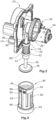
- Fig.2 the electric motor 24 can be seen.
- the second gear stage 26 for driving a valve is also visible.
- a valve rod 30, which is connected to the gate 28, also carries out a translatory movement as a result.
- the gate 28 and the valve rod 30 are subjected to a pressure load by a compression spring 32.
- the compression spring 32 is supported on a contact surface 34 on an annular projection 36 on the actuator housing 20 and on a second contact surface 39 on the gate 28, so that the valve is preloaded in the closing direction.
- valve rod 30 Due to the rotation of the eccentrically designed unit on the actuator 22 and as a result of the interaction of this unit with the gate 28, a translational up and down movement of the valve rod 30 takes place.
- a valve member 38 attached to the valve rod 30 can thus alternately separate and restore the fluidic connection between the inlet and the outlet of the housing.
- valve guide 40 which is fastened in a bore 50 in the housing 15.
- the valve guide 40 is designed to be largely rotationally symmetrical and resembles a hollow cylinder with a reduced diameter in the middle area.
- the valve guide 40 is fastened in the bore 50 by press or transition fits via cylindrical contact surfaces 42, 43 pointing in the circumferential direction.
- the contact surface 42 pointing towards the actuator 22 is provided with a recess 44 over part of its circumference or is interrupted so that a circumferential section with a reduced outer diameter is created, which no longer touches the inner wall of the bore 50 (see Fig.3 ).
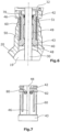
- valve guide 40 has a completely reduced outer diameter region 46 in the axially central region of the valve guide 40 as well as three completely circumferential material recesses or diameter increases 48, 49, 51 on its inner diameter (see Fig.6 ).
- the first diameter increase 48 is located on the side facing the valve member 38 and is designed as an internal bevel to facilitate the reception of the valve rod 30 during insertion.
- the second diameter increase 49 is located in the middle area of the valve guide 40 and has the purpose of reducing the contact area between the valve rod 30 and the valve guide 40.
- the third diameter increase 51 serves to accommodate a seal 70.
- the thick film heater 60 is attached in a meandering manner to the outer circumference of the valve guide 40, in the area 46 with a reduced outer diameter.
- the contact surface 43 of the valve guide 40 facing the valve member 38 is characterized by a transition or press fit over its entire circumference. Furthermore, the seal 70 is located between the valve rod 30 and the valve guide 40. Due to the transition or press fit between the valve guide 40 and the bore 50 of the housing 15 on the one hand, and with the help of the seal 70 between the valve rod 30 and the valve guide 40 on the other hand, ensures that if the valve device is used as an exhaust gas recirculation valve, no exhaust gases enter the actuator housing 20 and the connector housing 10. This ensures the functionality of the electric motor 24, the actuator gear and the electrical components, since corrosion and high temperatures caused by hot exhaust gases on, for example, gears, the control unit or the coils of the electric motor are prevented.
- valve guide 40 can be seen in the installed state within the actuator housing 20.
- the ends of the conductor track 62 of the thick-film heater 60 which function as the negative pole 80 and positive pole 82, protrude from the recess 44 parallel to the longitudinal axis of the valve rod 30.
- the exact position of the poles 80 and 82 corresponds to a material recess in the annular projection 36.
- the protruding poles 80 and 82 are electrically contacted with the contact lugs 90, which protrude from the connector housing 10.
- the contact lugs 90 are arranged in such a way that they correspond to the negative pole 80 and positive pole 82, that when the connector housing 10 is closed or fastened, a springy mechanical and thus also an electrical contact is automatically established.
- the thick-film heater 60 can provide a heat output.
- the heat produced is supplied to the deposits between the valve rod 30 and the valve guide 40 by means of heat conduction through the valve guide 40. In this way, the deposits are reduced. Furthermore, ice frozen during a cold start can be heated and evaporated, so that the valve rod 30 is prevented from getting stuck in the valve guide 40. The cleaning effect of the valve device that is achieved in this way maintains the functionality of the valve device.
- FIG 7 a second embodiment of the valve guide 40 or thick-film heating 60 is shown.
- the negative pole 80 and the positive pole 82 are not arranged parallel to the longitudinal axis of the valve guide 40 (cf. Fig.3 ), but run around the circumference of the valve guide 40.
- the two poles are axially spaced apart and run almost completely around the circumference, ie with a small interruption in the circumferential direction. The interruption is necessary due to the design in order to avoid a short circuit reaction between the negative pole 80 and the positive pole 82.
- the advantage of the second embodiment lies in the simplified assembly of the valve guide 40 in general, and in its simpler alignment within the bore 50 of the housing in particular.
- the exact position of the poles 80 and 82 was predetermined by the recess on the annular projection 36 of the actuator housing 20. Accordingly, in the first embodiment, the valve guide 40 must be rotated within the bore 50 until the negative pole 80 and the positive pole 82 are arranged corresponding to the recess on the annular projection 36.
- assembly is simpler in that less attention needs to be paid to the exact angle of rotation of the valve guide 40, since the negative pole 80 and the positive pole 82 extend over almost the entire circumference of the valve guide.
- valve device according to the invention significantly increases the service life, since functionality is maintained even at low temperatures and high physical stress caused by deposits.
- such a valve device is very quickly ready for operation immediately after a cold start and thus in phases of maximum pollutant emissions.
Landscapes
- Engineering & Computer Science (AREA)
- General Engineering & Computer Science (AREA)
- Mechanical Engineering (AREA)
- Chemical & Material Sciences (AREA)
- Combustion & Propulsion (AREA)
- Details Of Valves (AREA)
Description
- Die vorliegende Erfindung betrifft eine Ventilvorrichtung mit einem Gehäuse, das einen Einlass und einen Auslass aufweist, einem Strömungskanal, der zwischen dem Einlass und dem Auslass ausgebildet ist, einem Ventilglied, über den ein freier Querschnitt des Strömungskanals regelbar ist, einer mit dem Ventilglied verbundenen Ventilstange, die mittels eines Aktuators bewegbar ist, einer Bohrung im Gehäuse sowie einer in der Bohrung befestigten Ventilführung, die durch ein zumindest eine Leiterbahn aufweisendes Heizelement beheizbar ist.
- Derartige Ventilvorrichtungen kommen insbesondere in Verbrennungsmotoren als Abgasrückführventile zum Einsatz, können jedoch auch in anderen Anwendungen wie beispielsweise der Wärmerückgewinnung zu Heizzwecken eines Fahrgastinnenraums eingesetzt werden.
- In Verbrennungsmotoren entstehen während des Verbrennungsprozesses gesundheitsschädliche Stickoxide (NOx). Die Stickoxidkonzentrationen im Abgas korrelieren dabei exponentiell mit der Verbrennungstemperatur. Die Minderung der Stickoxidemissionen wird daher u.a. durch die Senkung der Verbrennungstemperatur herbeigeführt, welche letztlich mit Hilfe der Abgasrückführung (AGR) erfolgt. Hierbei wird heißes Abgas aus dem Abgaskanal durch Nutzung eines AGR-Ventils abgezweigt und dem Ansaugtrakt zugeleitet und dort mit Frischluft gemengt. Die höhere Wärmekapazität des Abgases gegenüber Frischluft senkt die Verbrennungstemperatur, da das vorhandene Kohlendioxid einen Teil der Verbrennungswärme absorbiert. Mit anderen Worten nimmt das Abgas an der Verbrennung nicht teil, muss jedoch mit aufgeheizt werden. Infolge der geringeren Verbrennungstemperatur entstehen schlussendlich weniger Stickoxidemissionen. Durch den Einsatz eines integrierten Abgaskühlers kann die Effizienz der Abgasrückführung gesteigert und folglich die Stickoxidemissionen zusätzlich gesenkt werden.
- Allerdings besteht bei der Abgasrückführung in Verbrennungsmotoren ein Zielkonflikt. Hohe AGR-Raten senken die NOx-Emissionen, fördern jedoch gleichzeitig die (Ruß-)Partikelkonzentrationen und den Wassergehalt im Abgasrückführkanal, wobei sich die Verunreinigungen bestehend aus Partikeln, Öldämpfen und Wasser im Zuge der Zeit zwischen der Ventilstange und der Ventilführung ablagern, wodurch sich die Ventilstange insbesondere bei wechselnden Temperaturen, wie nach dem Abstellen und Auskühlen des Verbrennungsmotors, festsetzen kann. Aus diesem Grund bedarf es einer Beheizung der Ventilstange, welche die Ablagerungen durch Wärmezufuhr loslöst bzw. sie durch Verdampfung der Flüssigkeiten im Abgas verhindert. Die verdampften Verunreinigungen können anschließend mit dem Abgasstrom fortgespült werden, sodass letztlich die Funktionsfähigkeit des AGR-Ventils nicht eingeschränkt wird. Eine derartige Anordnung zur thermischen Befreiung der Ventilstange von festgesetzten Ablagerungen wird beispielsweise in
DE 10 2014 109 273 A1 offenbart. - Aus der
FR 2 944 333 A1 - Die Aufgabe der vorliegenden Erfindung liegt somit darin, das Festsetzen der Ventilstange infolge von Verunreinigungen unter Zuhilfenahme einer Beheizung zu verhindern, wobei eine erleichterte, schadenfreie Montage gewährleistet werden soll und marktübliche Produktionskosten der Bauteile eingehalten werden sollen.
- Diese Aufgabe wird dadurch gelöst, dass die Ventilführung zumindest teilweise in ihrem Außendurchmesser reduziert und das Heizelement auf den in ihrem Außendurchmesser reduzierten Bereich der Ventilführung angeordnet ist. So ergeben sich im montierten Zustand sowohl Bereiche, in denen die Ventilführung durch Press- oder Übergangspassungen mit der Innenwand der Gehäusebohrung verbunden sind und an denen keine Leiterbahn des Heizelementes angeordnet ist, als auch solche, die Abstände zwischen der Ventilführung und der Innenwand der Gehäusebohrung aufweisen, wobei an diesen die Leiterbahn angeordnet ist. Angesichts der Tatsache, dass die Kontaktflächen zwischen der Ventilführung und der Gehäusebohrung sich nicht entlang der gesamten Ventilführungslänge erstrecken, ergibt sich darüber hinaus der Vorteil, dass eine geringere Reib- und damit auch geringere Anpresskraft während des Einpressens bzw. der Montage der Ventilführung erforderlich ist.
- Dadurch, dass ein Gehäuseteil, beispielsweise das Steckergehäuse, in dem sämtliche Bauteile für die Stromversorgung des Aktuators eingebaut sind und das folglich einen Stecker aufweist, Kontaktfahnen für die elektrische Versorgung des Heizelements umfasst, kann durch das Schließen des besagten Gehäuseteils automatisch die Verbindung zur stromführenden Beheizung auf der Ventilführung hergestellt werden. Die Kontaktfahnen ragen dabei im geöffneten Zustand des Steckergehäuses aus dem Inneren des Steckergehäuses hinaus. Wird nun das Steckergehäuse zum Schließen des Aktuatorgehäuses auf Letzteres montiert, liegen die Kontaktfahnen ohne weiteres Zutun federnd gegen die beiden Pole des um den Ventilführungsumfang angeordneten Heizelements an. Somit entfällt eine zusätzliche elektrische Kontaktierung der beheizbaren Ventilführung in Form von beispielsweise Klemmen, Steckkontakten oder stoffschlüssigen Verbindungen.
- Vorzugsweise ist das Heizelement durch eine elektrische Dickschichtbeheizung ausgebildet, welche auf der Außenseite und der im Durchmesser reduzierten Bereiche der Ventilführung aufgebracht ist. In Abgrenzung zu herkömmlichen Heizelementen können die Leiterbahnen der Dickschichtbeheizungen eine Breite von lediglich 1 Millimeter aufweisen, wodurch viele filigrane Formen, auch auf rohrförmigen Geometrien, möglich sind. Wichtigster Vorteil der Dickschichtbeheizung ist, dass sich die Leiterbahn näher am Material auftragen lässt. Hierdurch lässt sich die Wärme schneller und lokal sehr viel genauer verteilen. Des Weiteren ist eine stufenlose Steuerung der Wärmeleistung möglich.
- In einer bevorzugten Ausführung der Erfindung erstrecken sich die Enden der Leiterbahn des Heizelements zur Herstellung der Verbindung mit den Kontaktfahnen über den Ventilführungsumfang. Hierbei sind die als Plus- und Minuspol fungierenden Enden der Leiterbahn axial zueinander beabstandet. Auf diese Weise muss die genaue Orientierung der Ventilführung in Drehwinkelrichtung innerhalb der Gehäusebohrung während des Montagevorgangs nicht beachtet werden, wodurch ein vereinfachter und schneller Einbau gewährleistet wird, da die aus dem Steckergehäuse herausragenden Kontaktfahnen korrespondierend zu den sich über den Ventilführungsumfang erstreckenden Enden der Leiterbahn axial übereinander liegend angeordnet sind und entsprechend federnd gegen die Enden anliegen.
- In einer alternativen vorteilhaften Ausführung sind die Enden der Leiterbahn (62) parallel axial nebeneinander und korrespondierend zu den Kontaktfahnen (90) angeordnet, die federnd gegen die Enden der Leiterbahn (62) anliegen. Dabei korrespondieren die Positionen der Kontaktfahnen zu denen der Enden der Leiterbahn. Auf diese Weise wird die elektrische Kontaktierung des Heizelements sichergestellt.
- Vorzugsweise verläuft die Leiterbahn auf der Außenseite der Ventilführung mäanderförmig. Durch diese Ausgestaltung wird die elektrisch produzierte Wärme durch die Ventilführung gleichmäßig geleitet. Ferner kann durch die mäanderförmige Ausführung eine große Leiterbahnfläche realisiert und damit einhergehend den Verunreinigungen eine hohe Wärmeleistung zugeführt werden. Zudem können die beiden Enden der Leiterbahn unmittelbar nebeneinander angeordnet werden, unabhängig vom Verlauf der Leiterbahn zwischen ihren Enden. Dies erleichtert die elektrische Kontaktierung über die Kontaktfahnen.
- In einer alternativen vorteilhaften Ausführung der Erfindung ist die Leiterbahn auf der Außenseite der Ventilführung spiralförmig ausgebildet. Auch auf diese Weise wird über den Umfang eine gleichmäßige Erwärmung der Ventilführung und letztendlich der Verunreinigungen bzw. Ablagerungen gewährleistet.
- In einer besonders bevorzugten Ausführung der Erfindung betätigt der Aktuator die Ventilstange innerhalb der Ventilführung translatorisch. Hierbei führt die Ventilstange und damit einhergehend auch das Ventilglied eine lineare Bewegung aus, sodass die fluidische Verbindung zwischen Ein- und Auslass der Ventilvorrichtung sowohl hergestellt als auch unterbrochen werden kann.
- In einer alternativen Ausführung der Erfindung wird die Ventilstange durch den Aktuator rotatorisch bewegt. Dies kann beispielsweise zur Beheizung der Ventilführungen von Abgasklappen oder AGR-Klappen in größeren Motoren Anwendung finden.
- Vorteilhafterweise sind zwischen der Ventilführung und der Innenwand der Bohrung des Gehäuses mindestens zwei Berührungsflächen ausgebildet, die axial zueinander beabstandet sind. Mit Hilfe dieser ausreichenden Anzahl an Kontaktflächen wird die Ventilführung in der Bohrung befestigt und eine etwaige Bewegung im Betrieb unterbunden. Auf diese Weise wird das zweckmäßige Gleiten der Ventilstange innerhalb der Ventilführung sichergestellt.
- Vorzugsweise erstrecken sich die Berührungsflächen zwischen der Ventilführung und der Innenwand der Gehäusebohrung über den Ventilführungsumfang. So wird die sichere Befestigung der Ventilführung gewährleistet. Hierbei erstreckt sich zumindest die zum Ventilglied weisende Berührungsfläche vollumfänglich über die Ventilführung, so dass durch die Übergangs- oder Presspassung zwischen Ventilführung und Gehäusebohrung auch eine Abdichtungsfunktion gegenüber dem Abgas erfüllt wird.
- Weiterhin ist es vorteilhaft, dass die näher zum Aktuator (22) angeordnete Berührungsfläche (42) über einen Umfangsabschnitt unterbrochen ist, wobei die Ventilführung (40) in diesem Umfangsabschnitt in ihrem Außendurchmesser reduziert ist, wobei die kleinste Bogenlänge des im Durchmesser reduzierten Umfangsabschnitts mindestens der zweifachen Breite der Leiterbahn (62) entspricht. Der als Aussparung ausgebildete Umfangsabschnitt muss hierbei hinlänglich groß sein, damit die Enden der auf der Ventilführung angeordneten Leiterbahn überstehen, um letztendlich die elektrische Verbindung des Heizelementes zu den Kontaktfahnen herstellen zu können. So können die Enden der Leiterbahnen axial in den Bereich der Berührungsfläche gelegt werden, so dass Fehler bei der Kontaktierung durch einen Drehwinkelversatz beim Einbau ausgeschlossen werden.
- Vorteilhafterweise sind die beiden Berührungsflächen jeweils an den axialen Enden der Ventilführung ausgebildet. Diese Ausführung gewährleistet eine große Stabilität bzw. Biegesteifigkeit der Ventilführung.
- Des Weiteren befinden sich in einer hierzu weiterführenden Ausführung an der zum Aktuator weisenden Berührungsfläche mindestens drei die Gehäusebohrung berührende Abschnitte, die gleichmäßig über den Umfang verteilt angeordnet sind. So wird sichergestellt, dass eine etwaige Bewegung der Ventilführung in alle Richtungen innerhalb jeder Ebene quer zur Ventilstangenachse unterbunden wird.
- Vorzugsweise ist die Ventilführung in zumindest einem axialen Abschnitt in ihrem Innendurchmesser vollumfänglich erweitert ausgebildet, wodurch die Montage der Ventilstange erleichtert und deren Verschleiß reduziert wird. Zusätzlich können auf diese Weise Aufnahmen für Dichtelemente geschaffen werden.
- Es wird somit eine Ventilvorrichtung geschaffen, welche eine lange Lebensdauer aufweist, da durch die Wärmezufuhr Ablagerungen und somit ein Festsetzen der Ventilstange bzw. ein Funktionsausfall des Ventils verhindert wird. Dabei werden die Produktionskosten und der Montageaufwand gering gehalten.
- Weitere Einzelheiten und Vorteile der vorliegenden Erfindung ergeben sich aus der nachfolgenden Beschreibung der Ausführungsbeispiele in Verbindung mit den Zeichnungen.
-
Figur 1 zeigt eine Seitenansicht des Gehäuses einer erfindungsgemäßen Ventilvorrichtung. -
Figur 2 zeigt eine perspektivische Ansicht der erfindungsgemäßen Ventilvorrichtung ausFigur 1 bei ausgeblendetem Aktuatorgehäuse. -
Figur 3 zeigt eine perspektivische Ansicht der Ventilführung mit mäanderförmiger Dickschichtbeheizung ausFigur 2 . -
Figur 4 zeigt einen Ausschnitt einer perspektivischen Ansicht der Ventilführung im innerhalb der Bohrung des Aktuatorgehäuses montierten Zustand. -
Figur 5 zeigt einen Ausschnitt einer perspektivischen Ansicht der Ventilführung im elektrisch kontaktierten Zustand der mäanderförmigen Dickschichtbeheizung über die Kontaktfahnen aus dem Steckergehäuse. -
Figur 6 zeigt einen Ausschnitt einer Seitenansicht der Ventilführung in geschnittener Darstellung. -
Figur 7 zeigt die Seitenansicht eines zweiten Ausführungsbeispiels der Dickschichtbeheizung mit ringförmig und parallel zueinander verlaufenden Enden der Leiterbahn. - Die in den Figuren dargestellte Ventilvorrichtung weist ein Gehäuse 15 auf, welches aus einem Steckergehäuse 10 und einem Aktuatorgehäuse 20 besteht. Im Steckergehäuse 10 sind sämtliche Bauteile für die Stromversorgung eines Aktuators 22 inklusive einer nicht dargestellten Steuereinheit für einen Elektromotor 24 eingebaut. Am Steckergehäuse 10 ist ein Stecker 12 zur elektrischen Kontaktierung der Ventilvorrichtung nach außen ausgebildet. Darüber hinaus beherbergt das Steckergehäuse 10 eine erste, nicht dargestellte Getriebestufe zur Betätigung des Ventils. Ein Ritzel dieser ersten Getriebestufe ist auf einer Antriebswelle des Elektromotors 24 befestigt, wobei der Elektromotor 24 selbst im Aktuatorgehäuse 20 untergebracht ist.
- In
Fig. 2 ist der Elektromotor 24 zu sehen. Des Weiteren ist die zweite Getriebestufe 26 zum Antrieb eines Ventils ersichtlich. Durch die Bestromung des Elektromotors 24 wird über die beiden Getriebestufen eine als Exzenter ausgebildete Einheit derart in Bewegung versetzt, dass eine translatorische Bewegung einer Kulisse 28 hervorgerufen wird. Eine Ventilstange 30, welche mit der Kulisse 28 verbunden ist, führt hierdurch ebenfalls eine translatorische Bewegung aus. Dabei erfahren die Kulisse 28 und die Ventilstange 30 durch eine Druckfeder 32 eine Druckbelastung. Die Druckfeder 32 wird hierbei auf einer Anlagefläche 34 an einem ringförmigen Vorsprung 36 am Aktuatorgehäuse 20 und auf einer zweiten Anlagefläche 39 an der Kulisse 28 abgestützt, so dass das Ventil in Schließrichtung vorgespannt wird. - Aufgrund der Rotation der exzentrisch ausgebildeten Einheit am Aktuator 22 sowie infolge der Wechselwirkung dieser Einheit mit der Kulisse 28 erfolgt eine translatorische Auf- und Ab-Bewegung der Ventilstange 30. Ein an der Ventilstange 30 befestigtes Ventilglied 38 kann auf diese Weise die fluidische Verbindung zwischen dem Einlass und dem Auslass des Gehäuses abwechselnd trennen und wiederherstellen.
- Die translatorische Bewegung der Ventilstange 30 erfolgt innerhalb einer Ventilführung 40, die in einer Bohrung 50 im Gehäuse 15 befestigt ist. Die Ventilführung 40 ist hierbei weitestgehend rotationssymmetrisch ausgebildet und gleicht einem Hohlzylinder mit reduziertem Durchmesser im mittleren Bereich. An den axial beabstandeten Endbereichen größeren Außendurchmessers erfolgt die Befestigung der Ventilführung 40 in der Bohrung 50 durch Press- oder Übergangspassungen über zylindrisch in Umfangsrichtung weisende Berührungsflächen 42, 43. Hierbei ist die zum Aktuator 22 weisende Berührungsfläche 42 über einen Teil ihres Umfangs mit einer Ausnehmung 44 versehen beziehungsweise unterbrochen, so dass ein Umfangsabschnitt mit verringertem Außendurchmesser entsteht, der die Innenwand der Bohrung 50 nicht mehr berührt, (siehe
Fig. 3 ). - Des Weiteren weist die Ventilführung 40 einen vollumfänglich im Außendurchmesser reduzierten Bereich 46 im axial mittleren Bereich der Ventilführung 40 sowie drei vollumfängliche Materialaussparungen bzw. Durchmessererhöhungen 48, 49, 51 an ihrem Innendurchmesser auf (siehe
Fig. 6 ). Die erste Durchmessererhöhung 48 befindet sich an der zum Ventilglied 38 weisenden Seite und ist als Innenfase ausgebildet, um die Aufnahme der Ventilstange 30 beim Einführen zu erleichtern. Die zweite Durchmessererhöhung 49 befindet sich im mittleren Bereich der Ventilführung 40 und hat zum Zweck, die Kontaktfläche zwischen Ventilstange 30 und Ventilführung 40 zu verringern. Die dritte Durchmessererhöhung 51 dient der Aufnahme einer Dichtung 70. Die Dickschichtbeheizung 60 ist auf dem Außenumfang der Ventilführung 40, im Außendurchmesser reduzierten Bereich 46, mäanderförmig befestigt. - Das Einpressen der Ventilführung 40 in die Bohrung 50 des Gehäuses 15 wird aufgrund des im Außendurchmesser reduzierten Bereichs 46 der Ventilführung 40 und damit einhergehend aufgrund einer geringeren Reibungsfläche erleichtert. Darüber hinaus erfolgt infolge der verringerten Kontaktfläche zwischen der im Betrieb translatorisch bewegten Ventilstange 30 und der stets feststehenden Ventilführung 40 das Gleiten der Ventilstange 30 unter geringerem Energieaufwand. Ferner wird die Wärmeproduktion aufgrund der verringerten Gleitreibung zwischen der Ventilstange 30 und der Ventilführung 40 möglichst minimiert.
- Die zum Ventilglied 38 weisende Berührungsfläche 43 der Ventilführung 40 ist durch eine Übergangs- oder Presspassung über ihren vollständigen Umfang gekennzeichnet. Des Weiteren befindet sich die Dichtung 70 zwischen der Ventilstange 30 und der Ventilführung 40. Durch die Übergangs- bzw. Presspassung zwischen der Ventilführung 40 und der Bohrung 50 des Gehäuses 15 einerseits, sowie mit Hilfe der Dichtung 70 zwischen der Ventilstange 30 und der Ventilführung 40 andererseits wird gewährleistet, dass im Falle einer Anwendung der Ventilvorrichtung als Abgasrückführventil keine Abgase in das Aktuatorgehäuse 20 und das Steckergehäuse 10 gelangen. Hierdurch wird die Funktionstüchtigkeit des Elektromotors 24, des Aktuatorgetriebes sowie der elektrischen Bauteile sichergestellt, da Korrosion und hohe Temperaturen durch heiße Abgase an beispielsweise Zahnrädern, an der Steuereinheit oder den Spulen des Elektromotors verhindert werden.
- In
Fig. 4 ist die Ventilführung 40 im eingebauten Zustand innerhalb des Aktuatorgehäuses 20 zu sehen. Die Enden der Leiterbahn 62 der Dickschichtbeheizung 60, welche als Minuspol 80 und Pluspol 82 fungieren, ragen dabei an der Ausnehmung 44 parallel zur Längsachse der Ventilstange 30 hinaus. Dabei korrespondiert die genaue Lage der Pole 80 und 82 mit einer im ringförmigen Vorsprung 36 befindlichen Materialaussparung. Die überstehenden Pole 80 und 82 werden im Betrieb mit den Kontaktfahnen 90, welche aus dem Steckergehäuse 10 hinausragen, elektrisch kontaktiert. Hierbei sind die Kontaktfahnen 90 derart korrespondierend zum Minuspol 80 und Pluspol 82 angeordnet, dass beim Verschließen bzw. bei der Befestigung des Steckergehäuses 10 ein federnder mechanischer und somit auch ein elektrischer Kontakt automatisch hergestellt wird. - Infolge der elektrischen Kontaktierung kann die Dickschichtbeheizung 60 eine Wärmeleistung erbringen. Die produzierte Wärme wird mittels Wärmeleitung durch die Ventilführung 40 den Ablagerungen zwischen der Ventilstange 30 und der Ventilführung 40 zugeführt. Auf diese Weise werden die Ablagerungen verringert. Ferner kann bei einem Kaltstart gefrorenes Eis erhitzt und verdampft werden, sodass ein Festsetzen der Ventilstange 30 in der Ventilführung 40 verhindert wird. Der Reinigungseffekt der Ventilvorrichtung, der hierdurch bewerkstelligt wird, erhält so die Funktionstüchtigkeit der Ventilvorrichtung aufrecht.
- In
Figur 7 ist ein zweites Ausführungsbeispiel der Ventilführung 40 bzw. Dickschichtbeheizung 60 dargestellt. Der Minuspol 80 und der Pluspol 82 sind hierbei in Abgrenzung zum ersten Ausführungsbeispiel nicht parallel zur Längsachse der Ventilführung 40 angeordnet (vgl.Fig. 3 ), sondern verlaufen um den Umfang der Ventilführung 40. Dabei sind die beiden Pole axial beabstandet und verlaufen nahezu vollumfänglich, d.h. mit einer kleinen Unterbrechung in Umfangsrichtung. Die Unterbrechung ist hierbei konstruktionsbedingt erforderlich, um eine Kurzschlussreaktion zwischen dem Minuspol 80 und dem Pluspol 82 zu vermeiden. - Der Vorteil des zweiten Ausführungsbeispiels liegt in der vereinfachten Montage der Ventilführung 40 im Allgemeinen, und in ihrer einfacheren Ausrichtung innerhalb der Bohrung 50 des Gehäuses im Besonderen. Im ersten Ausführungsbeispiel war die genaue Position der Pole 80 und 82 durch die Ausnehmung am ringförmigen Vorsprung 36 des Aktuatorgehäuses 20 vorgegeben. Entsprechend ist im ersten Ausführungsbeispiel die Ventilführung 40 innerhalb der Bohrung 50 soweit zu drehen, bis das Minuspol 80 und das Pluspol 82 korrespondierend zur Ausnehmung am ringförmigen Vorsprung 36 angeordnet sind. Im Fall des zweiten Ausführungsbeispiels hingegen ist die Montage insofern einfacher, als dem exakten Drehwinkel der Ventilführung 40 weniger Beachtung geschenkt werden muss, da sich das Minuspol 80 und das Pluspol 82 über nahezu den gesamten Ventilführungsumfang erstrecken.
- Durch die erfindungsgemäße Ventilvorrichtung wird die Lebensdauer deutlich erhöht, da die Funktionsfähigkeit auch bei tiefen Temperaturen und hohen physikalischen Belastungen durch auftretende Ablagerungen erhalten bleibt. Insbesondere ist eine derartige Ventilvorrichtung unmittelbar nach dem Kaltstart und somit in Phasen höchsten Schadstoffausstoßes sehr schnell betriebsbereit.
Claims (15)
- Ventilvorrichtung für eine Verbrennungskraftmaschine miteinem Gehäuse (15), das einen Einlass (16) und einen Auslass (18) aufweist,einem Strömungskanal (19), der zwischen dem Einlass (16) und dem Auslass (18) ausgebildet ist,einem Ventilglied (38), über den ein freier Querschnitt des Strömungskanals regelbar ist,einer mit dem Ventilglied (38) verbundenen Ventilstange (30), die mittels eines Aktuators (22) bewegbar ist,einer Bohrung im Gehäuse (15) sowieeiner in der Bohrung (50) befestigten Ventilführung (40), die durch ein Heizelement (60, 61) beheizbar ist,dadurch gekennzeichnet, dassdas Heizelement (60, 61) zumindest eine Leiterbahn (62) aufweist, unddie Ventilführung (40) zumindest teilweise in ihrem Außendurchmesser reduziert und das Heizelement (60, 61) auf den in ihrem Außendurchmesser reduzierten Bereich (46) der Ventilführung (40) angeordnet ist.
- Ventilvorrichtung nach Anspruch 1, dadurch gekennzeichnet, dass ein Steckergehäuse (10), an dem ein Stecker (12) ausgebildet ist, Kontaktfahnen (90) aufweist, über die das Heizelement (60, 61) elektrisch kontaktiert ist.
- Ventilvorrichtung nach Anspruch 2, dadurch gekennzeichnet, dass das Heizelement (60, 61) durch eine elektrische Dickschichtbeheizung (60) ausgebildet ist.
- Ventilvorrichtung nach Anspruch 2 oder 3, dadurch gekennzeichnet, dass die Enden der Leiterbahn (62) des Heizelements (60, 61) zur Herstellung der Verbindung mit den Kontaktfahnen (90) sich über den Ventilführungsumfang erstrecken, wobei das erste Ende axial beabstandet zum zweiten Ende angeordnet ist, und die beiden Enden parallel zueinander verlaufen.
- Ventilvorrichtung nach Anspruch 2, dadurch gekennzeichnet, dass die Enden der Leiterbahn (62) parallel axial nebeneinander und korrespondierend zu den Kontaktfahnen (90) angeordnet sind, die federnd gegen die Enden der Leiterbahn (62) anliegen.
- Ventilvorrichtung nach einem der vorhergehenden Ansprüche, dadurch gekennzeichnet, dass die Leiterbahn (62), zumindest zwischen den Enden der Leiterbahn (62), mäanderförmig ausgebildet ist.
- Ventilvorrichtung nach einem der Ansprüche 1 bis 5, dadurch gekennzeichnet, dass die Leiterbahn (62), zumindest zwischen den Enden der Leiterbahn, spiralförmig ausgebildet ist.
- Ventilvorrichtung nach einem der vorangegangenen Ansprüche, dadurch gekennzeichnet, dass die vom Aktuator (22) betätigte Ventilstange (30) innerhalb der Ventilführung (40) eine translatorische Bewegung ausführt.
- Ventilvorrichtung nach einem der Ansprüche 1 bis 7, dadurch gekennzeichnet, dass die vom Aktuator (22) betätigte Ventilstange (30) innerhalb der Ventilführung (40) eine rotatorische Bewegung ausführt.
- Ventilvorrichtung nach einem der vorangegangenen Ansprüche, dadurch gekennzeichnet, dass zwischen der Ventilführung (40) und der Innenwand der Bohrung (50) des Gehäuses (15) mindestens zwei Berührungsflächen (42, 43) axial beabstandet zueinander ausgebildet sind.
- Ventilvorrichtung nach Anspruch 10, dadurch gekennzeichnet, dass die Berührungsflächen (42, 43) zwischen der Ventilführung (40) und der Bohrung (50) des Gehäuses (15) sich über ihren Umfang erstrecken.
- Ventilvorrichtung nach Anspruch 10, dadurch gekennzeichnet, dass die näher zum Aktuator (22) angeordnete Berührungsfläche (42) über einen Umfangsabschnitt unterbrochen ist, wobei die Ventilführung (40) in diesem Umfangsabschnitt in ihrem Außendurchmesser reduziert ist, wobei die kleinste Bogenlänge des im Durchmesser reduzierten Umfangsabschnitts mindestens der zweifachen Breite der Leiterbahn (62) entspricht.
- Ventilvorrichtung nach einem der Ansprüche 10 bis 12, dadurch gekennzeichnet, dass jeweils eine Berührungsfläche (42, 43) an den axialen Enden der Ventilführung (40) ausgebildet ist.
- Ventilvorrichtung nach Anspruch 10, dadurch gekennzeichnet, dass an der zum Aktuator (22) weisenden Berührungsfläche (42) mindestens drei die Bohrung (50) des Gehäuses (15) berührende Umfangsabschnitte ausgebildet sind.
- Ventilvorrichtung nach einem der vorhergehenden Ansprüche, dadurch gekennzeichnet, dass die Ventilführung (40) in zumindest einem axialen Abschnitt in ihrem Innendurchmesser vollumfänglich erweitert ausgebildet ist.
Applications Claiming Priority (1)
| Application Number | Priority Date | Filing Date | Title |
|---|---|---|---|
| PCT/EP2019/053490 WO2020164695A1 (de) | 2019-02-13 | 2019-02-13 | Ventilvorrichtung |
Publications (2)
| Publication Number | Publication Date |
|---|---|
| EP3924614A1 EP3924614A1 (de) | 2021-12-22 |
| EP3924614B1 true EP3924614B1 (de) | 2024-04-17 |
Family
ID=65440958
Family Applications (1)
| Application Number | Title | Priority Date | Filing Date |
|---|---|---|---|
| EP19705484.4A Active EP3924614B1 (de) | 2019-02-13 | 2019-02-13 | Ventilvorrichtung |
Country Status (2)
| Country | Link |
|---|---|
| EP (1) | EP3924614B1 (de) |
| WO (1) | WO2020164695A1 (de) |
Cited By (1)
| Publication number | Priority date | Publication date | Assignee | Title |
|---|---|---|---|---|
| RU232904U1 (ru) * | 2024-12-13 | 2025-03-26 | Общество с ограниченной ответственностью "РСГ ГРУПП" | Задвижка клиновая |
Families Citing this family (1)
| Publication number | Priority date | Publication date | Assignee | Title |
|---|---|---|---|---|
| CN114001171A (zh) * | 2021-11-17 | 2022-02-01 | 西诺威阀门控制(苏州)有限公司 | 一种超低温顶装式浮动球阀阀组 |
Family Cites Families (8)
| Publication number | Priority date | Publication date | Assignee | Title |
|---|---|---|---|---|
| US5758826A (en) * | 1996-03-29 | 1998-06-02 | Siemens Automotive Corporation | Fuel injector with internal heater |
| DE19959854A1 (de) * | 1999-12-10 | 2001-06-13 | Heraeus Electro Nite Int | Verfahren zur Abgasrückführung in einem Luftansaugbereich von Fahrzeug-Brennkraftmaschinen sowie Vorrichtung |
| DE10232072B4 (de) * | 2002-07-15 | 2005-03-24 | Robert Bosch Gmbh | Verfahren zur Reinigung eines von einem Gasstrom umströmten Messelementes |
| FR2902470B1 (fr) * | 2006-06-19 | 2010-12-10 | Peugeot Citroen Automobiles Sa | Systeme de rechauffage du siege de soupape d'une vanne egr |
| FR2944333A1 (fr) | 2009-04-09 | 2010-10-15 | Peugeot Citroen Automobiles Sa | Vanne comprenant un element chauffant electrique |
| ES2409116T3 (es) * | 2010-09-23 | 2013-06-25 | Andreas Massold | Procedimiento para la medición de temperatura en un vehículo. |
| DE102014109273A1 (de) | 2014-07-02 | 2016-01-07 | Pierburg Gmbh | Regelventil zum Anbau an einen Kfz-Motor |
| DE102016010772A1 (de) * | 2016-09-08 | 2018-03-08 | Eichenauer Heizelemente Gmbh & Co. Kg | Heizelement zum Beheizen eines Regelventils |
-
2019
- 2019-02-13 EP EP19705484.4A patent/EP3924614B1/de active Active
- 2019-02-13 WO PCT/EP2019/053490 patent/WO2020164695A1/de not_active Ceased
Cited By (1)
| Publication number | Priority date | Publication date | Assignee | Title |
|---|---|---|---|---|
| RU232904U1 (ru) * | 2024-12-13 | 2025-03-26 | Общество с ограниченной ответственностью "РСГ ГРУПП" | Задвижка клиновая |
Also Published As
| Publication number | Publication date |
|---|---|
| EP3924614A1 (de) | 2021-12-22 |
| WO2020164695A1 (de) | 2020-08-20 |
Similar Documents
| Publication | Publication Date | Title |
|---|---|---|
| EP2997249B1 (de) | Abgasventilvorrichtung für eine verbrennungskraftmaschine | |
| DE102020115516A1 (de) | Wegeventil und Ventilkäfig für ein Wegeventil | |
| DE102013107293B4 (de) | Steuerventileinheit für Kühlkreisläufe eines Kraftfahrzeugs | |
| DE102014104578B4 (de) | Klappenvorrichtung für eine Verbrennungskraftmaschine | |
| DE102021111839A1 (de) | Vorrichtung zur Handhabung von Fluid eines zumindest teilweise elektrisch angetriebenen Fahrzeugs | |
| EP4004413A1 (de) | Drehschieberventil für einen kühlkreislauf | |
| EP3147474A1 (de) | Elektrisch angetriebenes ventil | |
| DE10041579A1 (de) | Ventilanordnung mit Doppelklappe und Wärmebrücke für ein Abgasrückführungssystem und Verfahren zu deren Betrieb | |
| DE102012220432A1 (de) | Vorheizeinrichtung für eine Kraftstoffeinspritzanlage | |
| EP3227540B1 (de) | Klappenvorrichtung für eine verbrennungskraftmaschine | |
| EP3924614B1 (de) | Ventilvorrichtung | |
| EP2942500A1 (de) | Abgaswärmetauscher mit bypassrohr | |
| DE102007037359A1 (de) | Drosselvorrichtung für ein strömendes Medium | |
| DE102017107688A1 (de) | Ventilanordnung für ein Kühlsystem eines Fahrzeugs | |
| DE102017206128B4 (de) | Stelleinrichtung und zugehöriges Herstellungsverfahren | |
| EP3510835B1 (de) | Ringförmiges heizelement | |
| DE69904400T2 (de) | Steuervorrichtung zum öffnen und schliessen von mindestens einer luftzufuhrleitung eines zylinderkopfes einer brennkraftmaschine | |
| DE10142411A1 (de) | Einstückige Ventilklappe und Rotationsventil | |
| DE102014208420A1 (de) | Ventilbetätigungseinrichtung für einen Ventiltrieb einer Brennkraftmaschine | |
| WO2019057401A1 (de) | Stellvorrichtung mit einem abgedichteten führungszylinder | |
| DE202011051982U1 (de) | Kanal für ein gasförmiges Medium mit einer Klappe | |
| EP3234336B1 (de) | Ventilklappenanordnung einer ventilvorrichtung, und eine entsprechende ventilvorrichtung | |
| DE102016203707B4 (de) | Aktuatoranordnung für einen Antriebsstrang eines Kraftfahrzeugs | |
| DE102022206150B4 (de) | Steckverbinder und Steckverbinderanordnung | |
| DE102009036284A1 (de) | Ventilvorrichtung für eine Verbrennungskraftmaschine |
Legal Events
| Date | Code | Title | Description |
|---|---|---|---|
| STAA | Information on the status of an ep patent application or granted ep patent |
Free format text: STATUS: UNKNOWN |
|
| STAA | Information on the status of an ep patent application or granted ep patent |
Free format text: STATUS: THE INTERNATIONAL PUBLICATION HAS BEEN MADE |
|
| PUAI | Public reference made under article 153(3) epc to a published international application that has entered the european phase |
Free format text: ORIGINAL CODE: 0009012 |
|
| STAA | Information on the status of an ep patent application or granted ep patent |
Free format text: STATUS: REQUEST FOR EXAMINATION WAS MADE |
|
| 17P | Request for examination filed |
Effective date: 20210902 |
|
| AK | Designated contracting states |
Kind code of ref document: A1 Designated state(s): AL AT BE BG CH CY CZ DE DK EE ES FI FR GB GR HR HU IE IS IT LI LT LU LV MC MK MT NL NO PL PT RO RS SE SI SK SM TR |
|
| DAV | Request for validation of the european patent (deleted) | ||
| DAX | Request for extension of the european patent (deleted) | ||
| GRAP | Despatch of communication of intention to grant a patent |
Free format text: ORIGINAL CODE: EPIDOSNIGR1 |
|
| STAA | Information on the status of an ep patent application or granted ep patent |
Free format text: STATUS: GRANT OF PATENT IS INTENDED |
|
| RIC1 | Information provided on ipc code assigned before grant |
Ipc: F16K 41/02 20060101ALI20231121BHEP Ipc: F16K 31/52 20060101ALI20231121BHEP Ipc: F16K 1/00 20060101ALI20231121BHEP Ipc: F16K 49/00 20060101ALI20231121BHEP Ipc: F02M 26/73 20160101ALI20231121BHEP Ipc: F02M 26/65 20160101AFI20231121BHEP |
|
| INTG | Intention to grant announced |
Effective date: 20231207 |
|
| GRAS | Grant fee paid |
Free format text: ORIGINAL CODE: EPIDOSNIGR3 |
|
| GRAA | (expected) grant |
Free format text: ORIGINAL CODE: 0009210 |
|
| STAA | Information on the status of an ep patent application or granted ep patent |
Free format text: STATUS: THE PATENT HAS BEEN GRANTED |
|
| AK | Designated contracting states |
Kind code of ref document: B1 Designated state(s): AL AT BE BG CH CY CZ DE DK EE ES FI FR GB GR HR HU IE IS IT LI LT LU LV MC MK MT NL NO PL PT RO RS SE SI SK SM TR |
|
| REG | Reference to a national code |
Ref country code: GB Ref legal event code: FG4D Free format text: NOT ENGLISH |
|
| REG | Reference to a national code |
Ref country code: CH Ref legal event code: EP |
|
| REG | Reference to a national code |
Ref country code: IE Ref legal event code: FG4D Free format text: LANGUAGE OF EP DOCUMENT: GERMAN Ref country code: DE Ref legal event code: R096 Ref document number: 502019011056 Country of ref document: DE |
|
| REG | Reference to a national code |
Ref country code: LT Ref legal event code: MG9D |
|
| REG | Reference to a national code |
Ref country code: NL Ref legal event code: MP Effective date: 20240417 |
|
| PG25 | Lapsed in a contracting state [announced via postgrant information from national office to epo] |
Ref country code: NL Free format text: LAPSE BECAUSE OF FAILURE TO SUBMIT A TRANSLATION OF THE DESCRIPTION OR TO PAY THE FEE WITHIN THE PRESCRIBED TIME-LIMIT Effective date: 20240417 |
|
| PG25 | Lapsed in a contracting state [announced via postgrant information from national office to epo] |
Ref country code: NL Free format text: LAPSE BECAUSE OF FAILURE TO SUBMIT A TRANSLATION OF THE DESCRIPTION OR TO PAY THE FEE WITHIN THE PRESCRIBED TIME-LIMIT Effective date: 20240417 |
|
| PG25 | Lapsed in a contracting state [announced via postgrant information from national office to epo] |
Ref country code: IS Free format text: LAPSE BECAUSE OF FAILURE TO SUBMIT A TRANSLATION OF THE DESCRIPTION OR TO PAY THE FEE WITHIN THE PRESCRIBED TIME-LIMIT Effective date: 20240817 |
|
| PG25 | Lapsed in a contracting state [announced via postgrant information from national office to epo] |
Ref country code: BG Free format text: LAPSE BECAUSE OF FAILURE TO SUBMIT A TRANSLATION OF THE DESCRIPTION OR TO PAY THE FEE WITHIN THE PRESCRIBED TIME-LIMIT Effective date: 20240417 |
|
| PG25 | Lapsed in a contracting state [announced via postgrant information from national office to epo] |
Ref country code: HR Free format text: LAPSE BECAUSE OF FAILURE TO SUBMIT A TRANSLATION OF THE DESCRIPTION OR TO PAY THE FEE WITHIN THE PRESCRIBED TIME-LIMIT Effective date: 20240417 Ref country code: FI Free format text: LAPSE BECAUSE OF FAILURE TO SUBMIT A TRANSLATION OF THE DESCRIPTION OR TO PAY THE FEE WITHIN THE PRESCRIBED TIME-LIMIT Effective date: 20240417 |
|
| PG25 | Lapsed in a contracting state [announced via postgrant information from national office to epo] |
Ref country code: GR Free format text: LAPSE BECAUSE OF FAILURE TO SUBMIT A TRANSLATION OF THE DESCRIPTION OR TO PAY THE FEE WITHIN THE PRESCRIBED TIME-LIMIT Effective date: 20240718 |
|
| PG25 | Lapsed in a contracting state [announced via postgrant information from national office to epo] |
Ref country code: PT Free format text: LAPSE BECAUSE OF FAILURE TO SUBMIT A TRANSLATION OF THE DESCRIPTION OR TO PAY THE FEE WITHIN THE PRESCRIBED TIME-LIMIT Effective date: 20240819 |
|
| PG25 | Lapsed in a contracting state [announced via postgrant information from national office to epo] |
Ref country code: ES Free format text: LAPSE BECAUSE OF FAILURE TO SUBMIT A TRANSLATION OF THE DESCRIPTION OR TO PAY THE FEE WITHIN THE PRESCRIBED TIME-LIMIT Effective date: 20240417 |
|
| PG25 | Lapsed in a contracting state [announced via postgrant information from national office to epo] |
Ref country code: PL Free format text: LAPSE BECAUSE OF FAILURE TO SUBMIT A TRANSLATION OF THE DESCRIPTION OR TO PAY THE FEE WITHIN THE PRESCRIBED TIME-LIMIT Effective date: 20240417 |
|
| PG25 | Lapsed in a contracting state [announced via postgrant information from national office to epo] |
Ref country code: LV Free format text: LAPSE BECAUSE OF FAILURE TO SUBMIT A TRANSLATION OF THE DESCRIPTION OR TO PAY THE FEE WITHIN THE PRESCRIBED TIME-LIMIT Effective date: 20240417 |
|
| PG25 | Lapsed in a contracting state [announced via postgrant information from national office to epo] |
Ref country code: PT Free format text: LAPSE BECAUSE OF FAILURE TO SUBMIT A TRANSLATION OF THE DESCRIPTION OR TO PAY THE FEE WITHIN THE PRESCRIBED TIME-LIMIT Effective date: 20240819 Ref country code: PL Free format text: LAPSE BECAUSE OF FAILURE TO SUBMIT A TRANSLATION OF THE DESCRIPTION OR TO PAY THE FEE WITHIN THE PRESCRIBED TIME-LIMIT Effective date: 20240417 Ref country code: NO Free format text: LAPSE BECAUSE OF FAILURE TO SUBMIT A TRANSLATION OF THE DESCRIPTION OR TO PAY THE FEE WITHIN THE PRESCRIBED TIME-LIMIT Effective date: 20240717 Ref country code: LV Free format text: LAPSE BECAUSE OF FAILURE TO SUBMIT A TRANSLATION OF THE DESCRIPTION OR TO PAY THE FEE WITHIN THE PRESCRIBED TIME-LIMIT Effective date: 20240417 Ref country code: IS Free format text: LAPSE BECAUSE OF FAILURE TO SUBMIT A TRANSLATION OF THE DESCRIPTION OR TO PAY THE FEE WITHIN THE PRESCRIBED TIME-LIMIT Effective date: 20240817 Ref country code: HR Free format text: LAPSE BECAUSE OF FAILURE TO SUBMIT A TRANSLATION OF THE DESCRIPTION OR TO PAY THE FEE WITHIN THE PRESCRIBED TIME-LIMIT Effective date: 20240417 Ref country code: GR Free format text: LAPSE BECAUSE OF FAILURE TO SUBMIT A TRANSLATION OF THE DESCRIPTION OR TO PAY THE FEE WITHIN THE PRESCRIBED TIME-LIMIT Effective date: 20240718 Ref country code: FI Free format text: LAPSE BECAUSE OF FAILURE TO SUBMIT A TRANSLATION OF THE DESCRIPTION OR TO PAY THE FEE WITHIN THE PRESCRIBED TIME-LIMIT Effective date: 20240417 Ref country code: ES Free format text: LAPSE BECAUSE OF FAILURE TO SUBMIT A TRANSLATION OF THE DESCRIPTION OR TO PAY THE FEE WITHIN THE PRESCRIBED TIME-LIMIT Effective date: 20240417 Ref country code: BG Free format text: LAPSE BECAUSE OF FAILURE TO SUBMIT A TRANSLATION OF THE DESCRIPTION OR TO PAY THE FEE WITHIN THE PRESCRIBED TIME-LIMIT Effective date: 20240417 Ref country code: RS Free format text: LAPSE BECAUSE OF FAILURE TO SUBMIT A TRANSLATION OF THE DESCRIPTION OR TO PAY THE FEE WITHIN THE PRESCRIBED TIME-LIMIT Effective date: 20240717 |
|
| PG25 | Lapsed in a contracting state [announced via postgrant information from national office to epo] |
Ref country code: DK Free format text: LAPSE BECAUSE OF FAILURE TO SUBMIT A TRANSLATION OF THE DESCRIPTION OR TO PAY THE FEE WITHIN THE PRESCRIBED TIME-LIMIT Effective date: 20240417 |
|
| REG | Reference to a national code |
Ref country code: DE Ref legal event code: R097 Ref document number: 502019011056 Country of ref document: DE |
|
| PG25 | Lapsed in a contracting state [announced via postgrant information from national office to epo] |
Ref country code: EE Free format text: LAPSE BECAUSE OF FAILURE TO SUBMIT A TRANSLATION OF THE DESCRIPTION OR TO PAY THE FEE WITHIN THE PRESCRIBED TIME-LIMIT Effective date: 20240417 |
|
| PG25 | Lapsed in a contracting state [announced via postgrant information from national office to epo] |
Ref country code: CZ Free format text: LAPSE BECAUSE OF FAILURE TO SUBMIT A TRANSLATION OF THE DESCRIPTION OR TO PAY THE FEE WITHIN THE PRESCRIBED TIME-LIMIT Effective date: 20240417 |
|
| PG25 | Lapsed in a contracting state [announced via postgrant information from national office to epo] |
Ref country code: SK Free format text: LAPSE BECAUSE OF FAILURE TO SUBMIT A TRANSLATION OF THE DESCRIPTION OR TO PAY THE FEE WITHIN THE PRESCRIBED TIME-LIMIT Effective date: 20240417 Ref country code: RO Free format text: LAPSE BECAUSE OF FAILURE TO SUBMIT A TRANSLATION OF THE DESCRIPTION OR TO PAY THE FEE WITHIN THE PRESCRIBED TIME-LIMIT Effective date: 20240417 |
|
| PG25 | Lapsed in a contracting state [announced via postgrant information from national office to epo] |
Ref country code: SM Free format text: LAPSE BECAUSE OF FAILURE TO SUBMIT A TRANSLATION OF THE DESCRIPTION OR TO PAY THE FEE WITHIN THE PRESCRIBED TIME-LIMIT Effective date: 20240417 |
|
| PG25 | Lapsed in a contracting state [announced via postgrant information from national office to epo] |
Ref country code: SM Free format text: LAPSE BECAUSE OF FAILURE TO SUBMIT A TRANSLATION OF THE DESCRIPTION OR TO PAY THE FEE WITHIN THE PRESCRIBED TIME-LIMIT Effective date: 20240417 Ref country code: SK Free format text: LAPSE BECAUSE OF FAILURE TO SUBMIT A TRANSLATION OF THE DESCRIPTION OR TO PAY THE FEE WITHIN THE PRESCRIBED TIME-LIMIT Effective date: 20240417 Ref country code: RO Free format text: LAPSE BECAUSE OF FAILURE TO SUBMIT A TRANSLATION OF THE DESCRIPTION OR TO PAY THE FEE WITHIN THE PRESCRIBED TIME-LIMIT Effective date: 20240417 Ref country code: EE Free format text: LAPSE BECAUSE OF FAILURE TO SUBMIT A TRANSLATION OF THE DESCRIPTION OR TO PAY THE FEE WITHIN THE PRESCRIBED TIME-LIMIT Effective date: 20240417 Ref country code: DK Free format text: LAPSE BECAUSE OF FAILURE TO SUBMIT A TRANSLATION OF THE DESCRIPTION OR TO PAY THE FEE WITHIN THE PRESCRIBED TIME-LIMIT Effective date: 20240417 Ref country code: CZ Free format text: LAPSE BECAUSE OF FAILURE TO SUBMIT A TRANSLATION OF THE DESCRIPTION OR TO PAY THE FEE WITHIN THE PRESCRIBED TIME-LIMIT Effective date: 20240417 |
|
| PG25 | Lapsed in a contracting state [announced via postgrant information from national office to epo] |
Ref country code: IT Free format text: LAPSE BECAUSE OF FAILURE TO SUBMIT A TRANSLATION OF THE DESCRIPTION OR TO PAY THE FEE WITHIN THE PRESCRIBED TIME-LIMIT Effective date: 20240417 |
|
| PLBE | No opposition filed within time limit |
Free format text: ORIGINAL CODE: 0009261 |
|
| STAA | Information on the status of an ep patent application or granted ep patent |
Free format text: STATUS: NO OPPOSITION FILED WITHIN TIME LIMIT |
|
| REG | Reference to a national code |
Ref country code: DE Ref legal event code: R082 Ref document number: 502019011056 Country of ref document: DE Representative=s name: TERPATENT PARTGMBB, DE |
|
| 26N | No opposition filed |
Effective date: 20250120 |
|
| PG25 | Lapsed in a contracting state [announced via postgrant information from national office to epo] |
Ref country code: SI Free format text: LAPSE BECAUSE OF FAILURE TO SUBMIT A TRANSLATION OF THE DESCRIPTION OR TO PAY THE FEE WITHIN THE PRESCRIBED TIME-LIMIT Effective date: 20240417 |
|
| REG | Reference to a national code |
Ref country code: DE Ref legal event code: R119 Ref document number: 502019011056 Country of ref document: DE |
|
| PG25 | Lapsed in a contracting state [announced via postgrant information from national office to epo] |
Ref country code: SE Free format text: LAPSE BECAUSE OF FAILURE TO SUBMIT A TRANSLATION OF THE DESCRIPTION OR TO PAY THE FEE WITHIN THE PRESCRIBED TIME-LIMIT Effective date: 20240417 |
|
| PG25 | Lapsed in a contracting state [announced via postgrant information from national office to epo] |
Ref country code: MC Free format text: LAPSE BECAUSE OF FAILURE TO SUBMIT A TRANSLATION OF THE DESCRIPTION OR TO PAY THE FEE WITHIN THE PRESCRIBED TIME-LIMIT Effective date: 20240417 |
|
| REG | Reference to a national code |
Ref country code: CH Ref legal event code: PL |
|
| PG25 | Lapsed in a contracting state [announced via postgrant information from national office to epo] |
Ref country code: LU Free format text: LAPSE BECAUSE OF NON-PAYMENT OF DUE FEES Effective date: 20250213 |
|
| PG25 | Lapsed in a contracting state [announced via postgrant information from national office to epo] |
Ref country code: CH Free format text: LAPSE BECAUSE OF NON-PAYMENT OF DUE FEES Effective date: 20250228 |
|
| GBPC | Gb: european patent ceased through non-payment of renewal fee |
Effective date: 20250213 |
|
| REG | Reference to a national code |
Ref country code: BE Ref legal event code: MM Effective date: 20250228 |
|
| PG25 | Lapsed in a contracting state [announced via postgrant information from national office to epo] |
Ref country code: DE Free format text: LAPSE BECAUSE OF NON-PAYMENT OF DUE FEES Effective date: 20250902 |
|
| PG25 | Lapsed in a contracting state [announced via postgrant information from national office to epo] |
Ref country code: GB Free format text: LAPSE BECAUSE OF NON-PAYMENT OF DUE FEES Effective date: 20250213 |
|
| PG25 | Lapsed in a contracting state [announced via postgrant information from national office to epo] |
Ref country code: FR Free format text: LAPSE BECAUSE OF NON-PAYMENT OF DUE FEES Effective date: 20250228 |
|
| PG25 | Lapsed in a contracting state [announced via postgrant information from national office to epo] |
Ref country code: BE Free format text: LAPSE BECAUSE OF NON-PAYMENT OF DUE FEES Effective date: 20250228 |
|
| PG25 | Lapsed in a contracting state [announced via postgrant information from national office to epo] |
Ref country code: IE Free format text: LAPSE BECAUSE OF NON-PAYMENT OF DUE FEES Effective date: 20250213 |
|
| PG25 | Lapsed in a contracting state [announced via postgrant information from national office to epo] |
Ref country code: AT Free format text: LAPSE BECAUSE OF NON-PAYMENT OF DUE FEES Effective date: 20250213 |
|
| REG | Reference to a national code |
Ref country code: AT Ref legal event code: MM01 Ref document number: 1677472 Country of ref document: AT Kind code of ref document: T Effective date: 20250213 |