EP3923033B1 - Image processing device and image processing method - Google Patents
Image processing device and image processing method Download PDFInfo
- Publication number
- EP3923033B1 EP3923033B1 EP20752373.9A EP20752373A EP3923033B1 EP 3923033 B1 EP3923033 B1 EP 3923033B1 EP 20752373 A EP20752373 A EP 20752373A EP 3923033 B1 EP3923033 B1 EP 3923033B1
- Authority
- EP
- European Patent Office
- Prior art keywords
- image
- tomographic image
- tomographic
- frame
- output
- Prior art date
- Legal status (The legal status is an assumption and is not a legal conclusion. Google has not performed a legal analysis and makes no representation as to the accuracy of the status listed.)
- Active
Links
Images


Classifications
-
- G—PHYSICS
- G01—MEASURING; TESTING
- G01T—MEASUREMENT OF NUCLEAR OR X-RADIATION
- G01T1/00—Measuring X-radiation, gamma radiation, corpuscular radiation, or cosmic radiation
- G01T1/29—Measurement performed on radiation beams, e.g. position or section of the beam; Measurement of spatial distribution of radiation
- G01T1/2914—Measurement of spatial distribution of radiation
- G01T1/2985—In depth localisation, e.g. using positron emitters; Tomographic imaging (longitudinal and transverse section imaging; apparatus for radiation diagnosis sequentially in different planes, steroscopic radiation diagnosis)
-
- G—PHYSICS
- G06—COMPUTING OR CALCULATING; COUNTING
- G06T—IMAGE DATA PROCESSING OR GENERATION, IN GENERAL
- G06T12/00—Tomographic reconstruction from projections
-
- G—PHYSICS
- G06—COMPUTING OR CALCULATING; COUNTING
- G06T—IMAGE DATA PROCESSING OR GENERATION, IN GENERAL
- G06T12/00—Tomographic reconstruction from projections
- G06T12/20—Inverse problem, i.e. transformations from projection space into object space
-
- G—PHYSICS
- G06—COMPUTING OR CALCULATING; COUNTING
- G06T—IMAGE DATA PROCESSING OR GENERATION, IN GENERAL
- G06T2210/00—Indexing scheme for image generation or computer graphics
- G06T2210/41—Medical
-
- G—PHYSICS
- G06—COMPUTING OR CALCULATING; COUNTING
- G06T—IMAGE DATA PROCESSING OR GENERATION, IN GENERAL
- G06T2211/00—Image generation
- G06T2211/40—Computed tomography
- G06T2211/412—Dynamic
-
- G—PHYSICS
- G06—COMPUTING OR CALCULATING; COUNTING
- G06T—IMAGE DATA PROCESSING OR GENERATION, IN GENERAL
- G06T2211/00—Image generation
- G06T2211/40—Computed tomography
- G06T2211/441—AI-based methods, deep learning or artificial neural networks
Definitions
- the PET apparatus includes a detection unit having a large number of small radiation detectors arranged around a measurement space in which the object is placed.
- the PET apparatus detects a photon pair of an energy of 511 keV generated by electron-positron annihilation in the object into which a positron-emitting isotope (RI source) is introduced by a coincidence method using the detection unit, and collects coincidence information.
- RI source positron-emitting isotope
- the reconstructed tomographic image contains a lot of noise, and therefore, noise removal processing by an image filter is necessary.
- Examples of the image filter used for the noise removal include a Gaussian filter and a guided filter. Conventionally, the Gaussian filter is used. On the other hand, the guided filter is developed in recent years, and has a feature of being able to preserve a boundary of shading in the image compared to the Gaussian filter.
- An embodiment of the present invention is a radiation tomography system.
- the radiation tomography system includes a radiation tomography apparatus for collecting list data for reconstructing a tomographic image of an object; and the image processing apparatus of the above configuration for creating the tomographic image after the noise removal processing based on the list data collected by the radiation tomography apparatus.
- An embodiment of the present invention is an image processing method according to claim 7.
- a noise-removed tomographic image can be created with high performance based on list data collected by a radiation tomography apparatus.
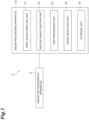
- FIG. 1 is a diagram illustrating a configuration of a radiation tomography system 1.
- the radiation tomography system 1 includes a radiation tomography apparatus 2 and an image processing apparatus 10.
- the image processing apparatus 10 includes a first image creation unit 11, a second image creation unit 12, a CNN processing unit 13, an image selection unit 14, and a storage unit 15.
- a computer including a CPU, a RAM, a ROM, a hard disk drive, and the like is used as the image processing apparatus 10.
- the image processing apparatus 10 includes an input unit (for example, a keyboard or a mouse) that receives an input of an operator, and a display unit (for example, a liquid crystal display) that displays an image and the like.
- an input unit for example, a keyboard or a mouse
- a display unit for example, a liquid crystal display
- the radiation tomography apparatus 2 is an apparatus for collecting list data for reconstructing a tomographic image of an object.
- Examples of the radiation tomography apparatus 2 include a PET apparatus and a SPECT apparatus.
- the radiation tomography apparatus 2 will be described as a PET apparatus.
- the list data includes identification information and detection time information of a pair of radiation detectors used in coincidence detection of the photon pair.
- the list data may further include energy information of photons detected by each radiation detector and detection time difference information of a pair of radiation detectors.
- the image processing apparatus 10 reconstructs a tomographic image based on the list data.
- a maximum likelihood expectation maximization (ML-EM) method and a successive approximation type image reconstruction technique based on a block iterative method obtained by improving the above method are known.
- ML-EM maximum likelihood expectation maximization
- successive approximation type image reconstruction technique by the block iterative method an ordered subset ML-EM (OSEM) method, a row-action maximum likelihood algorithm (RAMLA) method, a dynamic RAMLA (DRAMA) method, and the like are known.
- the image processing apparatus 10 creates a tomographic image after noise removal processing using a convolutional neural network (CNN).
- CNN convolutional neural network
- the first image creation unit 11 divides the list data into a plurality of frames (first to M-th frames) in a collection order, performs reconstruction processing for each of the plurality of frames using a data group included in the m-th frame in the list data, and creates a first tomographic image D m of the m-th frame.
- the first tomographic images D 1 to D M are dynamic PET images.
- the second image creation unit 12 creates a second tomographic image S m by performing reconstruction processing using a data group having a data amount larger than that of the data group used in creating the first tomographic image D m of the m-th frame in the list data in the first image creation unit 11.
- the second tomographic image S m may be a static PET image.
- the second tomographic image may be created for each frame, may be created in common for all frames, or may be created in common for some frames.
- the first image creation unit 11 and the second image creation unit 12 may be provided in common or may be provided separately.
- the CNN processing unit 13 inputs the second tomographic image S m to the CNN, and outputs an output tomographic image O m from the CNN.
- the CNN processing unit 13 compares the output tomographic image O m with the first tomographic image D m , and trains the CNN based on the comparison result.
- the CNN processing unit 13 repeats the above training operation, and generates the output tomographic image O m,n in each training.
- the output tomographic image O m,n is an output tomographic image output from the CNN after (n-1) times of training of the CNN using the first tomographic image D m and the second tomographic image S m for the m-th frame.
- the output tomographic image O m,1 is an output tomographic image output from the CNN in a state where no training has been performed.
- the image selection unit 14 selects, for each of the first to M-th frames, any one output tomographic image from the plurality of output tomographic images O m,1 to O m,N as the tomographic image after the noise removal processing.
- the image selection unit 14 selects one output tomographic image from the plurality of output tomographic images O m,1 to O m,N based on a comparison between the output tomographic image O m,n and the second tomographic image S m .
- an output tomographic image that minimizes the error between the output tomographic image O m,n and the second tomographic image S m may be selected, or any one output tomographic image in one or two or more output tomographic images with which the error between the output tomographic image O m,n and the second tomographic image S m becomes a threshold value or less may be selected. Further, a doctor, an operator, or the like may select one output tomographic image from the plurality of output tomographic images O m,1 to O m,N .
- the storage unit 15 stores the list data, and stores the first tomographic image D m and the second tomographic image S m of each frame. Further, the storage unit 15 stores the plurality of output tomographic images O m,1 to O m,N of each frame, and stores the output tomographic image selected from them.
- FIG. 3 is a flowchart illustrating an image processing method.
- the image processing method includes a list data acquisition step S10 for acquiring the list data collected by the radiation tomography apparatus 2, a first image creation step S11 performed by the first image creation unit 11, a second image creation step S12 performed by the second image creation unit 12, a CNN processing step S13 performed by the CNN processing unit 13, and an image selection step S14 performed by the image selection unit 14.
- the list data collected by the radiation tomography apparatus 2 is acquired.
- the list data is divided into the plurality of frames (first to M-th frames) in the collection order, and for each of the plurality of frames, reconstruction processing is performed using a data group included in the m-th frame in the list data to create the first tomographic image D m of the m-th frame.
- reconstruction processing is performed using a data group in the list data having a data amount larger than that of the data group used in creating the first tomographic image D m of the m-th frame in the first image creation unit 11 to create the second tomographic image S m .
- the first image creation step S11 and the second image creation step S12 may be performed in an arbitrary order or may be performed in parallel.
- the second tomographic image S m is input to the CNN, and the output tomographic image O m is output from the CNN.
- the CNN is trained based on a comparison between the output tomographic image O m and the first tomographic image D m .
- the above training operation is repeated to generate the output tomographic image O m,n in each training operation.
- one output tomographic image is selected from the plurality of output tomographic images O m,1 to O m,N as the tomographic image after the noise removal processing.
- FIG. 4 is a flowchart illustrating the operation of the CNN processing unit 13 and the CNN processing step S13.
- the CNN performs learning by being repeatedly trained N times, and the N output tomographic images O m,1 to O m,N are stored.
- the output tomographic image O m,n may be compared with the second tomographic image S m , and when the error between the images becomes a predetermined threshold value or less, the CNN processing step S13 may be terminated, and the finally obtained output tomographic image may be used as the tomographic image after the noise removal processing.
- FIG. 5 is a diagram illustrating the list data, the frame, the first tomographic image D m , and the second tomographic image S m .
- the horizontal axis represents the time for collecting the list data, and the time axis is divided into the plurality of frames.
- the first tomographic image D m of the m-th frame is a tomographic image reconstructed using a data group included in the m-th frame in the list data.
- the second tomographic image S m corresponding to the first tomographic image D m of the m-th frame is a tomographic image reconstructed using a data group with a data amount larger than that of the data group included in the m-th frame in the list data.
- the second tomographic image S m corresponding to the first tomographic image D m of the m-th frame is created using a data group with a data amount that is twice or more the data group of the m-th frame.
- the second tomographic image S m corresponding to the first tomographic image D m of the m-th frame may be created using a data group including the data group of the m-th frame, or may be created using a data group before and after the data group of the m-th frame.
- FIG. 6 is a graph showing a temporal change of acquisition frequency of coincidence information in the object into which the RI source is introduced.
- the frequency of electron-positron annihilation in the object into which the RI source is introduced increases with time immediately after the input of the RI source, reaches a peak at a certain time Tp, and gradually decreases after the peak.
- the period of each frame is set to be relatively short, and in a subsequent period in which the acquisition frequency of the coincidence information gradually decreases, the period of each frame is set to be relatively long. Further, it is known that the tomographic image is significantly different between the period from the time immediately after the input of the RI source until the acquisition frequency of the coincidence information reaches the peak (before the time Tp) and the period after the peak (after the time Tp).
- the second tomographic image S m corresponding to the first tomographic image D m of the m-th frame is preferably created using a data group before the time Tp in the list data.
- the second tomographic image S m corresponding to the first tomographic image D m of the m-th frame is preferably created using a data group after the time Tp in the list data.
- the second tomographic image S m corresponding to the first tomographic image D m of the m-th frame may be created using the entire list data.
- the second tomographic image S m corresponding to the first tomographic image D m of the m-th frame is preferably created by performing normalization such that the maximum pixel value of the second tomographic image S m is equal to the maximum pixel value of the first tomographic image D m . That is, it is preferable to use a normalized second tomographic image S' m expressed by the following Formula (1).
- MaxD m is the maximum pixel value in the first tomographic image D m of the m-th frame.
- MaxS m is the maximum pixel value in the second tomographic image S m corresponding to the first tomographic image D m of the m-th frame.
- a sinogram ((b) in FIG. 7 ) of each frame was created.
- the sinogram is a histogram of the coincidence information for each pair of radiation detectors in the radiation tomography apparatus 2.
- Each period for first to fourth frames was set to 20 seconds (subtotal 80 seconds)
- each period for fifth to eighth frames was set to 40 seconds (subtotal 160 seconds)
- each period for ninth to twelfth frames was set to 60 seconds (subtotal 240 seconds)
- each period for thirteenth to sixteenth frames was set to 180 seconds (subtotal 720 seconds)
- each period for seventeenth to thirtieth frames was set to 300 seconds (subtotal 4200 seconds)
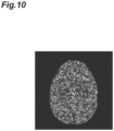
- FIG. 9 is a diagram showing a numerical phantom image.
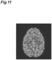
- FIG. 10 is a diagram showing a first tomographic image of a sixth frame.
- FIG. 11 is a diagram showing an image obtained by performing noise removal processing of a first comparative example on the first tomographic image of FIG. 10 .
- the noise removal processing of the first comparative example is processing by the Gaussian filter.
- FIG. 12 is a diagram showing an image obtained by performing noise removal processing of a second comparative example on the first tomographic image of FIG. 10 .
- the noise removal processing of the second comparative example is processing described in Non Patent Document 2.
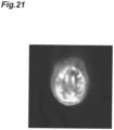
- FIG. 13 is a diagram showing an output tomographic image selected by performing the CNN processing of the present embodiment on the first tomographic image of FIG. 10 .
- a normalized second tomographic image S' m created using the entire list data is used.
- the boundary of the shading in the image is well preserved, and the noise is well removed, and in addition, the unnaturalness of the processed image is reduced.
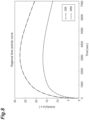
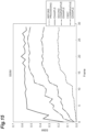
- FIG. 14 is a graph showing the temporal change of PSNR of the reconstructed image for each of the first comparative example, the second comparative example, and the present embodiment obtained in the simulation.
- the PSNR Peak Signal to Noise Ratio
- dB decibels
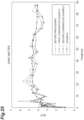
- FIG. 15 is a graph showing the temporal change of SSIM of the reconstructed image for each of the first comparative example, the second comparative example, and the present embodiment obtained in the simulation.
- the SSIM Structuretural Similarity Index
- the SSIM is an index for quantifying the change of the intensity, contrast, and structure in the image, and a higher value means better image quality.
- Both indexes of PSNR and SSIM show better performance for the noise removal processing of the present embodiment compared with the noise removal processing of the first and second comparative examples. For other frames also, the noise removal processing of the present embodiment has better performance.
- the second image creation unit may use, in creating the second tomographic image corresponding to the first tomographic image of each frame, a data group including the data group used in creating the first tomographic image of the frame in the first image creation unit. Further, the second image creation unit may use, in creating the second tomographic image corresponding to the first tomographic image of each frame, a data group before and after the data group used in creating the first tomographic image of the frame in the first image creation unit.
- the radiation tomography system of the above embodiment includes a radiation tomography apparatus for collecting list data for reconstructing a tomographic image of an object; and the image processing apparatus of the above configuration for creating the tomographic image after the noise removal processing based on the list data collected by the radiation tomography apparatus.
- the image processing method of the above embodiment is a method for creating a tomographic image after noise removal processing based on list data collected by a radiation tomography apparatus, and includes (1) a first image creation step of dividing the list data into a plurality of frames in a collection order, and performing reconstruction processing for each of the plurality of frames using a data group in the list data included in the frame to create a first tomographic image of the frame; (2) a second image creation step of performing reconstruction processing using a data group in the list data having a data amount larger than that of the data group used in creating the first tomographic image of each frame in the first image creation step to create a second tomographic image; and (3) a CNN processing step of
- 1 - radiation tomography system 1 - radiation tomography system
- 2 - radiation tomography apparatus 10 - image processing apparatus, 11 - first image creation unit, 12 - second image creation unit, 13 - CNN processing unit, 14 - image selection unit, 15 - storage unit.
Landscapes
- Physics & Mathematics (AREA)
- General Physics & Mathematics (AREA)
- Engineering & Computer Science (AREA)
- Theoretical Computer Science (AREA)
- Health & Medical Sciences (AREA)
- Life Sciences & Earth Sciences (AREA)
- High Energy & Nuclear Physics (AREA)
- Molecular Biology (AREA)
- Spectroscopy & Molecular Physics (AREA)
- Image Processing (AREA)
- Nuclear Medicine (AREA)
- Image Analysis (AREA)
Applications Claiming Priority (2)
| Application Number | Priority Date | Filing Date | Title |
|---|---|---|---|
| JP2019020467A JP7237624B2 (ja) | 2019-02-07 | 2019-02-07 | 画像処理装置および画像処理方法 |
| PCT/JP2020/003268 WO2020162296A1 (ja) | 2019-02-07 | 2020-01-29 | 画像処理装置および画像処理方法 |
Publications (3)
| Publication Number | Publication Date |
|---|---|
| EP3923033A1 EP3923033A1 (en) | 2021-12-15 |
| EP3923033A4 EP3923033A4 (en) | 2022-11-16 |
| EP3923033B1 true EP3923033B1 (en) | 2025-06-25 |
Family
ID=71947437
Family Applications (1)
| Application Number | Title | Priority Date | Filing Date |
|---|---|---|---|
| EP20752373.9A Active EP3923033B1 (en) | 2019-02-07 | 2020-01-29 | Image processing device and image processing method |
Country Status (5)
| Country | Link |
|---|---|
| US (1) | US11893660B2 (https=) |
| EP (1) | EP3923033B1 (https=) |
| JP (1) | JP7237624B2 (https=) |
| CN (1) | CN113454489B (https=) |
| WO (1) | WO2020162296A1 (https=) |
Families Citing this family (8)
| Publication number | Priority date | Publication date | Assignee | Title |
|---|---|---|---|---|
| JP7562223B2 (ja) * | 2020-11-17 | 2024-10-07 | キヤノンメディカルシステムズ株式会社 | 核医学診断装置および核医学データ処理装置 |
| WO2023106479A1 (ko) * | 2021-12-10 | 2023-06-15 | 광주과학기술원 | Ste 및 최적 중단시점 자동 결정 알고리즘을 적용한 dip를 사용하여 노이즈 이미지를 디노이징하는 방법 및 장치 |
| KR102476433B1 (ko) * | 2021-12-22 | 2022-12-12 | 이화여자대학교 산학협력단 | 신경망을 이용하여 영상의 노이즈를 저감하기 위한 학습 및 복원 방법과 이를 수행하는 컴퓨팅 장치 |
| JP2023112818A (ja) * | 2022-02-02 | 2023-08-15 | 浜松ホトニクス株式会社 | 画像処理装置および画像処理方法 |
| JP2023173737A (ja) * | 2022-05-26 | 2023-12-07 | 浜松ホトニクス株式会社 | 画像処理装置および画像処理方法 |
| JP7815033B2 (ja) * | 2022-05-31 | 2026-02-17 | 浜松ホトニクス株式会社 | 画像処理装置および画像処理方法 |
| JP2024054668A (ja) * | 2022-10-05 | 2024-04-17 | 浜松ホトニクス株式会社 | 画像処理装置および画像処理方法 |
| WO2025142535A1 (ja) * | 2023-12-27 | 2025-07-03 | 浜松ホトニクス株式会社 | 画像処理装置および画像処理方法 |
Family Cites Families (16)
| Publication number | Priority date | Publication date | Assignee | Title |
|---|---|---|---|---|
| US10964075B2 (en) | 2004-01-13 | 2021-03-30 | Spectrum Dynamics Llc | Gating with anatomically varying durations |
| CN103955899A (zh) | 2014-05-02 | 2014-07-30 | 南方医科大学 | 基于组合图像引导的动态pet图像去噪方法 |
| US20180018757A1 (en) | 2016-07-13 | 2018-01-18 | Kenji Suzuki | Transforming projection data in tomography by means of machine learning |
| CN110234400B (zh) | 2016-09-06 | 2021-09-07 | 医科达有限公司 | 用于生成合成医学图像的神经网络 |
| US10621756B2 (en) | 2017-01-13 | 2020-04-14 | Canon Medical Systems Corporation | Apparatus and method for correcting bias in low-count computed tomography projection data |
| RU2667879C1 (ru) * | 2017-05-30 | 2018-09-24 | Общество с ограниченной ответственностью "Аби Продакшн" | Обработка и анализ данных на изображениях компьютерной томографии |
| WO2019100511A1 (en) * | 2017-11-22 | 2019-05-31 | Zhejiang Dahua Technology Co., Ltd. | An image processing method and system |
| WO2019161043A1 (en) * | 2018-02-15 | 2019-08-22 | GE Precision Healthcare LLC | System and method for synthesizing magnetic resonance images |
| JP7262933B2 (ja) | 2018-05-25 | 2023-04-24 | キヤノンメディカルシステムズ株式会社 | 医用情報処理システム、医用情報処理装置、放射線診断装置、超音波診断装置、学習用データの生産方法及びプログラム |
| US10685445B2 (en) * | 2018-06-09 | 2020-06-16 | Uih-Rt Us Llc | Systems and methods for generating augmented segmented image set |
| CN109166161B (zh) | 2018-07-04 | 2023-06-30 | 东南大学 | 一种基于噪声伪影抑制卷积神经网络的低剂量ct图像处理系统 |
| CN109009179B (zh) | 2018-08-02 | 2020-09-18 | 浙江大学 | 基于深度置信网络的相同同位素标记双示踪剂pet分离方法 |
| US10991092B2 (en) * | 2018-08-13 | 2021-04-27 | Siemens Healthcare Gmbh | Magnetic resonance imaging quality classification based on deep machine-learning to account for less training data |
| US11446008B2 (en) * | 2018-08-17 | 2022-09-20 | Tokitae Llc | Automated ultrasound video interpretation of a body part with one or more convolutional neural networks |
| CN109272472B (zh) | 2018-10-15 | 2022-07-15 | 天津大学 | 面向医用能谱ct图像的噪声及伪影消除方法 |
| US11222447B2 (en) * | 2020-05-06 | 2022-01-11 | Siemens Medical Solutions Usa, Inc. | Inter-frame motion correction in whole-body direct parametric image reconstruction |
-
2019
- 2019-02-07 JP JP2019020467A patent/JP7237624B2/ja active Active
-
2020
- 2020-01-29 WO PCT/JP2020/003268 patent/WO2020162296A1/ja not_active Ceased
- 2020-01-29 EP EP20752373.9A patent/EP3923033B1/en active Active
- 2020-01-29 US US17/428,693 patent/US11893660B2/en active Active
- 2020-01-29 CN CN202080012799.XA patent/CN113454489B/zh active Active
Also Published As
| Publication number | Publication date |
|---|---|
| EP3923033A4 (en) | 2022-11-16 |
| WO2020162296A1 (ja) | 2020-08-13 |
| US11893660B2 (en) | 2024-02-06 |
| JP7237624B2 (ja) | 2023-03-13 |
| CN113454489B (zh) | 2024-07-26 |
| US20220114772A1 (en) | 2022-04-14 |
| JP2020128882A (ja) | 2020-08-27 |
| CN113454489A (zh) | 2021-09-28 |
| EP3923033A1 (en) | 2021-12-15 |
Similar Documents
| Publication | Publication Date | Title |
|---|---|---|
| EP3923033B1 (en) | Image processing device and image processing method | |
| Park et al. | Unpaired image denoising using a generative adversarial network in X-ray CT | |
| US12444098B2 (en) | Image processing device and image processing method | |
| CN110097611B (zh) | 图像重建方法、装置、设备及存储介质 | |
| US20100260402A1 (en) | Image analysis | |
| CN114387236B (zh) | 基于卷积神经网络的低剂量Sinogram去噪与PET图像重建方法 | |
| US11481937B2 (en) | Positron emission tomography image reconstruction method | |
| Humphries et al. | Comparison of deep learning approaches to low dose CT using low intensity and sparse view data | |
| Whiteley et al. | FastPET: Near real-time PET reconstruction from histo-images using a neural network | |
| JP6974159B2 (ja) | 画像処理装置および画像処理方法 | |
| CN105488824B (zh) | 一种重建pet图像的方法和装置 | |
| US12266102B2 (en) | Attenuation distribution image creating device, image processing device, radiation computed tomography system, attenuation distribution image creating method, and image processing method | |
| JP6495615B2 (ja) | 画像処理装置および画像処理方法 | |
| US20250157099A1 (en) | Image processing device and image processing method | |
| US10636128B2 (en) | Recursive filter for space-variant images | |
| JP6986961B2 (ja) | 画像処理装置および画像処理方法 | |
| Suzuki et al. | Image Correction in Emission Tomography Using Deep Convolution Neural Network | |
| JP7018306B2 (ja) | 画像処理装置および画像処理方法 | |
| Liu et al. | Deep Spatial Spectral Convolutional Sparse Coding for Spectral CT Image Reconstruction | |
| Bian et al. | Dynamic PET image reconstruction using a spatial-temporal edge-preserving prior | |
| Wallis et al. | Comparison of the convergence properties of the It-W and OS-EM algorithms in SPECT | |
| Ronchetti et al. | Generative Tomography Reconstruction | |
| Whiteley | Deep Learning in Positron Emission Tomography Image Reconstruction | |
| Denisova | Regularized versus non-regularized statistical reconstruction techniques |
Legal Events
| Date | Code | Title | Description |
|---|---|---|---|
| STAA | Information on the status of an ep patent application or granted ep patent |
Free format text: STATUS: THE INTERNATIONAL PUBLICATION HAS BEEN MADE |
|
| PUAI | Public reference made under article 153(3) epc to a published international application that has entered the european phase |
Free format text: ORIGINAL CODE: 0009012 |
|
| STAA | Information on the status of an ep patent application or granted ep patent |
Free format text: STATUS: REQUEST FOR EXAMINATION WAS MADE |
|
| 17P | Request for examination filed |
Effective date: 20210830 |
|
| AK | Designated contracting states |
Kind code of ref document: A1 Designated state(s): AL AT BE BG CH CY CZ DE DK EE ES FI FR GB GR HR HU IE IS IT LI LT LU LV MC MK MT NL NO PL PT RO RS SE SI SK SM TR |
|
| DAV | Request for validation of the european patent (deleted) | ||
| DAX | Request for extension of the european patent (deleted) | ||
| A4 | Supplementary search report drawn up and despatched |
Effective date: 20221018 |
|
| RIC1 | Information provided on ipc code assigned before grant |
Ipc: G06T 11/00 20060101AFI20221012BHEP |
|
| REG | Reference to a national code |
Ref country code: DE Ref legal event code: R079 Free format text: PREVIOUS MAIN CLASS: G01T0001161000 Ipc: G06T0011000000 Ref document number: 602020053340 Country of ref document: DE |
|
| GRAP | Despatch of communication of intention to grant a patent |
Free format text: ORIGINAL CODE: EPIDOSNIGR1 |
|
| STAA | Information on the status of an ep patent application or granted ep patent |
Free format text: STATUS: GRANT OF PATENT IS INTENDED |
|
| RIC1 | Information provided on ipc code assigned before grant |
Ipc: G01T 1/29 20060101ALI20250121BHEP Ipc: G06T 11/00 20060101AFI20250121BHEP |
|
| INTG | Intention to grant announced |
Effective date: 20250205 |
|
| GRAS | Grant fee paid |
Free format text: ORIGINAL CODE: EPIDOSNIGR3 |
|
| GRAA | (expected) grant |
Free format text: ORIGINAL CODE: 0009210 |
|
| STAA | Information on the status of an ep patent application or granted ep patent |
Free format text: STATUS: THE PATENT HAS BEEN GRANTED |
|
| AK | Designated contracting states |
Kind code of ref document: B1 Designated state(s): AL AT BE BG CH CY CZ DE DK EE ES FI FR GB GR HR HU IE IS IT LI LT LU LV MC MK MT NL NO PL PT RO RS SE SI SK SM TR |
|
| REG | Reference to a national code |
Ref country code: GB Ref legal event code: FG4D |
|
| REG | Reference to a national code |
Ref country code: CH Ref legal event code: EP |
|
| REG | Reference to a national code |
Ref country code: CH Ref legal event code: EP |
|
| REG | Reference to a national code |
Ref country code: IE Ref legal event code: FG4D |
|
| REG | Reference to a national code |
Ref country code: DE Ref legal event code: R096 Ref document number: 602020053340 Country of ref document: DE |
|
| P01 | Opt-out of the competence of the unified patent court (upc) registered |
Free format text: CASE NUMBER: UPC_APP_1544_3923033/2025 Effective date: 20250730 |
|
| PG25 | Lapsed in a contracting state [announced via postgrant information from national office to epo] |
Ref country code: FI Free format text: LAPSE BECAUSE OF FAILURE TO SUBMIT A TRANSLATION OF THE DESCRIPTION OR TO PAY THE FEE WITHIN THE PRESCRIBED TIME-LIMIT Effective date: 20250625 |
|
| REG | Reference to a national code |
Ref country code: LT Ref legal event code: MG9D |
|
| PG25 | Lapsed in a contracting state [announced via postgrant information from national office to epo] |
Ref country code: GR Free format text: LAPSE BECAUSE OF FAILURE TO SUBMIT A TRANSLATION OF THE DESCRIPTION OR TO PAY THE FEE WITHIN THE PRESCRIBED TIME-LIMIT Effective date: 20250926 Ref country code: NO Free format text: LAPSE BECAUSE OF FAILURE TO SUBMIT A TRANSLATION OF THE DESCRIPTION OR TO PAY THE FEE WITHIN THE PRESCRIBED TIME-LIMIT Effective date: 20250925 |
|
| PG25 | Lapsed in a contracting state [announced via postgrant information from national office to epo] |
Ref country code: BG Free format text: LAPSE BECAUSE OF FAILURE TO SUBMIT A TRANSLATION OF THE DESCRIPTION OR TO PAY THE FEE WITHIN THE PRESCRIBED TIME-LIMIT Effective date: 20250625 |
|
| PG25 | Lapsed in a contracting state [announced via postgrant information from national office to epo] |
Ref country code: HR Free format text: LAPSE BECAUSE OF FAILURE TO SUBMIT A TRANSLATION OF THE DESCRIPTION OR TO PAY THE FEE WITHIN THE PRESCRIBED TIME-LIMIT Effective date: 20250625 |
|
| PG25 | Lapsed in a contracting state [announced via postgrant information from national office to epo] |
Ref country code: RS Free format text: LAPSE BECAUSE OF FAILURE TO SUBMIT A TRANSLATION OF THE DESCRIPTION OR TO PAY THE FEE WITHIN THE PRESCRIBED TIME-LIMIT Effective date: 20250925 |
|
| PG25 | Lapsed in a contracting state [announced via postgrant information from national office to epo] |
Ref country code: LV Free format text: LAPSE BECAUSE OF FAILURE TO SUBMIT A TRANSLATION OF THE DESCRIPTION OR TO PAY THE FEE WITHIN THE PRESCRIBED TIME-LIMIT Effective date: 20250625 |
|
| REG | Reference to a national code |
Ref country code: NL Ref legal event code: MP Effective date: 20250625 |
|
| PG25 | Lapsed in a contracting state [announced via postgrant information from national office to epo] |
Ref country code: NL Free format text: LAPSE BECAUSE OF FAILURE TO SUBMIT A TRANSLATION OF THE DESCRIPTION OR TO PAY THE FEE WITHIN THE PRESCRIBED TIME-LIMIT Effective date: 20250625 |
|
| PG25 | Lapsed in a contracting state [announced via postgrant information from national office to epo] |
Ref country code: PT Free format text: LAPSE BECAUSE OF FAILURE TO SUBMIT A TRANSLATION OF THE DESCRIPTION OR TO PAY THE FEE WITHIN THE PRESCRIBED TIME-LIMIT Effective date: 20251027 |
|
| REG | Reference to a national code |
Ref country code: AT Ref legal event code: MK05 Ref document number: 1807326 Country of ref document: AT Kind code of ref document: T Effective date: 20250625 |
|
| PG25 | Lapsed in a contracting state [announced via postgrant information from national office to epo] |
Ref country code: IS Free format text: LAPSE BECAUSE OF FAILURE TO SUBMIT A TRANSLATION OF THE DESCRIPTION OR TO PAY THE FEE WITHIN THE PRESCRIBED TIME-LIMIT Effective date: 20251025 |
|
| PG25 | Lapsed in a contracting state [announced via postgrant information from national office to epo] |
Ref country code: AT Free format text: LAPSE BECAUSE OF FAILURE TO SUBMIT A TRANSLATION OF THE DESCRIPTION OR TO PAY THE FEE WITHIN THE PRESCRIBED TIME-LIMIT Effective date: 20250625 Ref country code: SM Free format text: LAPSE BECAUSE OF FAILURE TO SUBMIT A TRANSLATION OF THE DESCRIPTION OR TO PAY THE FEE WITHIN THE PRESCRIBED TIME-LIMIT Effective date: 20250625 |
|
| PG25 | Lapsed in a contracting state [announced via postgrant information from national office to epo] |
Ref country code: CZ Free format text: LAPSE BECAUSE OF FAILURE TO SUBMIT A TRANSLATION OF THE DESCRIPTION OR TO PAY THE FEE WITHIN THE PRESCRIBED TIME-LIMIT Effective date: 20250625 |
|
| PG25 | Lapsed in a contracting state [announced via postgrant information from national office to epo] |
Ref country code: PL Free format text: LAPSE BECAUSE OF FAILURE TO SUBMIT A TRANSLATION OF THE DESCRIPTION OR TO PAY THE FEE WITHIN THE PRESCRIBED TIME-LIMIT Effective date: 20250625 |
|
| PG25 | Lapsed in a contracting state [announced via postgrant information from national office to epo] |
Ref country code: EE Free format text: LAPSE BECAUSE OF FAILURE TO SUBMIT A TRANSLATION OF THE DESCRIPTION OR TO PAY THE FEE WITHIN THE PRESCRIBED TIME-LIMIT Effective date: 20250625 |
|
| PG25 | Lapsed in a contracting state [announced via postgrant information from national office to epo] |
Ref country code: SK Free format text: LAPSE BECAUSE OF FAILURE TO SUBMIT A TRANSLATION OF THE DESCRIPTION OR TO PAY THE FEE WITHIN THE PRESCRIBED TIME-LIMIT Effective date: 20250625 |
|
| PG25 | Lapsed in a contracting state [announced via postgrant information from national office to epo] |
Ref country code: ES Free format text: LAPSE BECAUSE OF FAILURE TO SUBMIT A TRANSLATION OF THE DESCRIPTION OR TO PAY THE FEE WITHIN THE PRESCRIBED TIME-LIMIT Effective date: 20250625 |
|
| PG25 | Lapsed in a contracting state [announced via postgrant information from national office to epo] |
Ref country code: DK Free format text: LAPSE BECAUSE OF FAILURE TO SUBMIT A TRANSLATION OF THE DESCRIPTION OR TO PAY THE FEE WITHIN THE PRESCRIBED TIME-LIMIT Effective date: 20250625 |
|
| PGFP | Annual fee paid to national office [announced via postgrant information from national office to epo] |
Ref country code: DE Payment date: 20251203 Year of fee payment: 7 |
|
| PG25 | Lapsed in a contracting state [announced via postgrant information from national office to epo] |
Ref country code: IT Free format text: LAPSE BECAUSE OF FAILURE TO SUBMIT A TRANSLATION OF THE DESCRIPTION OR TO PAY THE FEE WITHIN THE PRESCRIBED TIME-LIMIT Effective date: 20250625 |
|
| PLBE | No opposition filed within time limit |
Free format text: ORIGINAL CODE: 0009261 |
|
| STAA | Information on the status of an ep patent application or granted ep patent |
Free format text: STATUS: NO OPPOSITION FILED WITHIN TIME LIMIT |