EP3922377A1 - Coiling machine, method for manufacturing coil spring, and coil spring - Google Patents
Coiling machine, method for manufacturing coil spring, and coil spring Download PDFInfo
- Publication number
- EP3922377A1 EP3922377A1 EP19914558.2A EP19914558A EP3922377A1 EP 3922377 A1 EP3922377 A1 EP 3922377A1 EP 19914558 A EP19914558 A EP 19914558A EP 3922377 A1 EP3922377 A1 EP 3922377A1
- Authority
- EP
- European Patent Office
- Prior art keywords
- wire
- laser light
- cutter
- coil spring
- irradiation
- Prior art date
- Legal status (The legal status is an assumption and is not a legal conclusion. Google has not performed a legal analysis and makes no representation as to the accuracy of the status listed.)
- Granted
Links
Images





Classifications
-
- B—PERFORMING OPERATIONS; TRANSPORTING
- B23—MACHINE TOOLS; METAL-WORKING NOT OTHERWISE PROVIDED FOR
- B23K—SOLDERING OR UNSOLDERING; WELDING; CLADDING OR PLATING BY SOLDERING OR WELDING; CUTTING BY APPLYING HEAT LOCALLY, e.g. FLAME CUTTING; WORKING BY LASER BEAM
- B23K26/00—Working by laser beam, e.g. welding, cutting or boring
- B23K26/352—Working by laser beam, e.g. welding, cutting or boring for surface treatment
- B23K26/354—Working by laser beam, e.g. welding, cutting or boring for surface treatment by melting
-
- B—PERFORMING OPERATIONS; TRANSPORTING
- B21—MECHANICAL METAL-WORKING WITHOUT ESSENTIALLY REMOVING MATERIAL; PUNCHING METAL
- B21F—WORKING OR PROCESSING OF METAL WIRE
- B21F11/00—Cutting wire
- B21F11/005—Cutting wire springs
-
- B—PERFORMING OPERATIONS; TRANSPORTING
- B21—MECHANICAL METAL-WORKING WITHOUT ESSENTIALLY REMOVING MATERIAL; PUNCHING METAL
- B21F—WORKING OR PROCESSING OF METAL WIRE
- B21F3/00—Coiling wire into particular forms
- B21F3/02—Coiling wire into particular forms helically
- B21F3/04—Coiling wire into particular forms helically externally on a mandrel or the like
-
- B—PERFORMING OPERATIONS; TRANSPORTING
- B21—MECHANICAL METAL-WORKING WITHOUT ESSENTIALLY REMOVING MATERIAL; PUNCHING METAL
- B21F—WORKING OR PROCESSING OF METAL WIRE
- B21F35/00—Making springs from wire
-
- B—PERFORMING OPERATIONS; TRANSPORTING
- B23—MACHINE TOOLS; METAL-WORKING NOT OTHERWISE PROVIDED FOR
- B23K—SOLDERING OR UNSOLDERING; WELDING; CLADDING OR PLATING BY SOLDERING OR WELDING; CUTTING BY APPLYING HEAT LOCALLY, e.g. FLAME CUTTING; WORKING BY LASER BEAM
- B23K26/00—Working by laser beam, e.g. welding, cutting or boring
- B23K26/0093—Working by laser beam, e.g. welding, cutting or boring combined with mechanical machining or metal-working covered by other subclasses than B23K
-
- B—PERFORMING OPERATIONS; TRANSPORTING
- B23—MACHINE TOOLS; METAL-WORKING NOT OTHERWISE PROVIDED FOR
- B23K—SOLDERING OR UNSOLDERING; WELDING; CLADDING OR PLATING BY SOLDERING OR WELDING; CUTTING BY APPLYING HEAT LOCALLY, e.g. FLAME CUTTING; WORKING BY LASER BEAM
- B23K26/00—Working by laser beam, e.g. welding, cutting or boring
- B23K26/02—Positioning or observing the workpiece, e.g. with respect to the point of impact; Aligning, aiming or focusing the laser beam
- B23K26/03—Observing, e.g. monitoring, the workpiece
- B23K26/034—Observing the temperature of the workpiece
-
- B—PERFORMING OPERATIONS; TRANSPORTING
- B23—MACHINE TOOLS; METAL-WORKING NOT OTHERWISE PROVIDED FOR
- B23K—SOLDERING OR UNSOLDERING; WELDING; CLADDING OR PLATING BY SOLDERING OR WELDING; CUTTING BY APPLYING HEAT LOCALLY, e.g. FLAME CUTTING; WORKING BY LASER BEAM
- B23K26/00—Working by laser beam, e.g. welding, cutting or boring
- B23K26/08—Devices involving relative movement between laser beam and workpiece
- B23K26/083—Devices involving movement of the workpiece in at least one axial direction
-
- B—PERFORMING OPERATIONS; TRANSPORTING
- B23—MACHINE TOOLS; METAL-WORKING NOT OTHERWISE PROVIDED FOR
- B23K—SOLDERING OR UNSOLDERING; WELDING; CLADDING OR PLATING BY SOLDERING OR WELDING; CUTTING BY APPLYING HEAT LOCALLY, e.g. FLAME CUTTING; WORKING BY LASER BEAM
- B23K26/00—Working by laser beam, e.g. welding, cutting or boring
- B23K26/60—Preliminary treatment
Definitions
- inventions described herein relate to a coiling machine configured to manufacture a coil spring, manufacturing method of a coil spring, and coil spring.
- a coil spring forming machine As a device configured to manufacture a coil spring, for example, a coil spring forming machine described in Patent Literature 1 is known.
- This coil spring forming machine calculates in advance a position of a cutting portion on the basis of a length of a wire to be formed into a helical shape, and cuts the wire at the cutting portion in a state where the cutting portion is softened by high-frequency heating.
- the cutting portion is heated by high-frequency heating, and hence the responsiveness of heating of the cutting portion is not good. Moreover, cutting is carried out in the state where the cutting portion is continuously heated by high-frequency heating, and hence there is sometimes a case where the members used for cutting are adversely affected by the high-frequency heating. Furthermore, regarding the high-frequency heating, the responsiveness of heating of the cutting portion is not sufficient, and the wire is coiled in the state where the wire is partially heated, and hence there is a possibility of the forming accuracy of the spring becoming difficult to be maintained constant.
- Present inventions make it one of the objects to provide a coiling machine and manufacturing method of a coil spring making it possible to easily cut a wire formed into a helical shape, and to further provide a coil spring excellent in quality.
- a coiling machine includes a laser heating machine configured to irradiate a wire formed into a helical shape with laser light to thereby heat a part of the wire, and cutting components configured to cut a portion of the wire after the irradiation of the laser light is stopped, a temperature of the portion being higher than before irradiated with the laser light.
- a manufacturing method of a coil spring according to the present invention includes irradiating a wire formed into a helical shape with laser light to thereby heat a part of the wire, and cutting a portion of the wire after the irradiation of the laser light is stopped, a temperature of the portion being higher than before irradiated with the laser light.
- a coil spring according to the present invention is formed of a wire including a first end and a second end opposite to the first end, the first end includes a first irradiation scar of laser light, the first irradiation scar includes a quench-hardened zone the hardness of which is higher than a base material of the wire, and a first heat affected zone which is positioned around the quench-hardened zone and the hardness of which is lower than the base material, and the first heat affected zone extends to at least a part of an end face of the first end.
- the present invention it is possible to provide a coiling machine and manufacturing method of a coil spring making it possible to easily cut a wire formed into a helical shape. Furthermore, according to the present invention, it is possible to provide a coil spring excellent in quality.
- FIG. 1 is a schematic perspective view showing the main part of a coiling machine 100 according to a first embodiment.
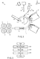
- FIG. 2 is a schematic front view of the coiling machine 100 of FIG. 1 .
- the X-direction, Y-direction, Z-direction, and ⁇ -direction are defined as shown in FIG. 1 and FIG. 2 .
- the X-direction, Y-direction, and Z-direction are orthogonal to each other.
- the X-direction is the wire-feeding direction.
- the Z-direction is the direction in which the helix of the coil spring is formed.
- the ⁇ -direction is the direction in which a wire constituting the coil spring is wound.
- the coiling machine 100 includes a helix forming unit 10, heating unit (laser heating machine 20), cutting unit 30, and control unit 40.
- the helix forming unit 10 forms the wire 1 which is the material for the coil spring into a helical shape while feeding the wire thereto.
- the helix forming unit 10 described above includes a pair of driving rollers 11, a pair of driven rollers 12, wire guide 13, first forming roller 14, second forming roller 15, and pitch tool 16.
- Each of the driving rollers 11 and each of the driven rollers 12 are opposed to each other with a gap held between them.
- each of the driven rollers 12 is rotated through the wire 1.
- the wire 1 pinched between each driving roller 11 and each driven roller 12 is moved in the X-direction shown in FIG. 1 and FIG. 2 .
- the wire 1 is inserted through the wire guide 13.
- the wire guide 13 guides the wire 1 in such a manner that the wire 1 moves straight ahead in the X-direction to thereby lead the wire 1 to the first forming roller 14.
- the first forming roller 14, second forming roller 15, and pitch tool 16 are arranged in this order in the ⁇ -direction and, when viewed from above, the order of their positions is different from the above in the Z-direction.
- the first forming roller 14 guides the wire 1 moving in the X-direction to the second forming roller 15 while bending the wire 1 into an arc-like shape and moving the wire 1 in the Y-direction shown in FIG. 1 .
- the second forming roller 15 guides the wire 1 moving forward in an arc-like shape to the pitch tool 16 while further bending the wire 1 into the arc-like shape.
- the wire 1 guided by the pitch tool 16 moves in the Z-direction shown in FIG. 1 in a helically-formed state.
- the laser heating machine 20 radiates laser light in such a manner as to heat a part of the wire 1 formed into a helical shape. Owing to the irradiation of the laser light, a heated portion 1V the temperature of which is higher than the other portions is formed in the wire 1.
- the laser heating machine 20 described above includes a laser oscillator 21, optical fiber 22, and beam-spot regulator 23.
- the laser oscillator 21 for example, a semiconductor laser configured to generate laser light can be used.
- the optical fiber 22 transmits the laser light generated by the laser oscillator 21 to the beam spot regulator 23.
- the beam spot regulator 23 modifies the beam shape of the laser light into a rectangular shape or circular shape.
- an optical element such as a beam homogenizer or the like can be used.
- the laser heating machine 20 may further include a measuring instrument 24 configured to measure the temperature of the heated portion 1V.
- the measuring instrument 24 includes, for example, a sensor configured to detect the temperature of the heated portion 1V of the wire 1.
- the measuring instrument 24 may be provided on the lateral side of the cutting unit 30.
- the measuring instrument 30 can also be configured in such a manner as to move away from the cutter 31 in conjunction with the operation of the cutter 31.
- the measurement result obtained by the measuring instrument 24 can be used for, for example, control of the timing for cutting the wire 1 to be carried out by the cutting unit 30.
- the measuring instrument 24 is not an indispensable configuration. That is, various conditions concerning cutting of the wire 1 may be set in advance without using the measuring instrument 24, and the cutting unit 30 may cut the heated portion 1V on the basis of the conditions.
- the laser heating machine 20 may further include a migration stage configured to move the beam spot regulator 23 closer to or away from the heated portion 1V of the wire 1.
- the migration stage can be constituted of, for example, a direct-acting stage or robot hand.
- the cutting unit 30 cuts the heated portion 1V of the wire 1 the temperature of which is higher than before being irradiated with the laser light after the irradiation of the laser light is stopped.
- the cutting unit 30 described above includes the cutter 31 and mandrel 32.
- the cutter 31 is arranged at a position between the second forming roller 15 and pitch tool 16, and above these members in the Y-direction.
- the cutter 31 includes a sharp cutting blade the cutting edge of which is in the Z-direction at a tip thereof.
- the cutter 31 is configured to be movable up and down in the Y-direction by means of a direct-acting stage not shown.
- the mandrel 32 is arranged inside the circular arc along which the first forming roller 14, second forming roller 15, and pitch tool 16 are arranged.
- the shape of the mandrel 32 in the X-Y plane is semicircular as shown in, for example, FIG. 2 , and extends to elongate in the Z-direction.
- the mandrel 32 supports the inner circumferential surface of the wire 1 formed into the helical shape on the upper part of the circular arc surface thereof.
- the control unit 40 controls the helix forming unit 10, laser heating machine 20, and cutting unit 30.
- the control unit 40 described above includes a controller 41.
- the controller 41 includes a read only memory (ROM), central processing unit (CPU), and random access memory (RAM).
- ROM stores therein computer programs for controlling the helix forming unit 10, laser heating machine 20, and cutting unit 30.
- the CPU executes the computer programs stored in the ROM.
- the RAM temporarily stores therein, while the computer programs are executed by the CPU, various data items occurring concomitantly with the execution of the computer programs.
- FIG. 3 is a flowchart concerning an operation of the coiling machine 100.
- the operation shown by the flowchart is realized by the controller 41 by executing the computer programs.
- the manufacturing process of the coil spring 2 to be carried out by the coiling machine 100 includes a helix forming step S01, heating step S02, and cutting step S03.
- the wire 1 is formed into a helical shape.
- a part of the wire 1 is irradiated with laser light, whereby the heated portion 1V is formed in the wire 1.
- the heated portion 1V includes a portion made softer than the other portions (base material) of the wire 1.
- the cutting step S03 after the heating step S02 is completed the heated portion 1V of the wire 1 is cut.
- FIG. 4 is a schematic perspective view of the coiling machine 100 showing a specific example of the helix forming step S01.
- the helix forming unit 10 makes the wire 1 move straight in the X-direction by means of the driving rollers 11 and driven rollers 12 to thereby lead the wire 1 to the wire guide 13.
- the wire 1 output from the wire guide 13 is formed into an arc-like shape by the first forming roller 14 and second forming roller 15.
- the wire 1 formed into the arc-like shape is guided by the pitch tool 16 in such a manner as to be formed into a helical shape having a predetermined pitch. Owing to such an operation, the helical wire 1 is gradually elongated in the Z-direction.
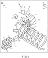
- FIG. 5 is a schematic perspective view of the coiling machine 100 showing a specific example of the heating step S02.
- the laser heating machine 20 directly irradiates, for example, the portion of the wire 1 formed into the helical shape positioned above (below the cutter 31) the end part of the mandrel 32 with laser light.
- the base material of the wire 1 is heated and a softened heated portion 1V is formed.
- the laser heating machine 20 is fixedly arranged at, for example, a predetermined position, and radiates laser light from this position toward a part of the stopped wire 1.
- the laser heating machine 20 may radiate laser light after making the beam spot regulator 23 close to the wire 1 as shown in FIG. 5 .
- the action of the laser heating machine 20 may also be controlled in such a manner that while the heating step S02 is executed, feeding of the wire 1 carried out by the helix forming unit 10 is not stopped, and the laser light irradiation position moves to follow the movement of the cutting position resulting from the coiling operation.
- FIG. 6 is a perspective view showing a first example of the method of softening a part of the wire 1 by heating.
- the laser heating machine 20 irradiates the surface of the wire 1 with laser light L1.
- the laser light L1 has a beam profile elongated in the width direction of the wire 1.
- a heated portion 1V is formed in the irradiated area 1a of the wire 1 irradiated with the laser light L1 and surrounding part thereof.
- FIG. 7 is a cross-sectional view of the wire 1 along line VII-VII in FIG. 6 .
- the heated portion 1V extends not only to the surrounding part of the irradiated area 1a on the surface of the wire 1, but also to the inside of the wire 1.
- the width WD1 of the laser light L1 in the width direction of the wire 1 is less than the diameter R of the wire 1. Accordingly, the most part of the laser light L1 is applied to the wire 1.
- FIG. 8 is a perspective view of the wire 1 showing a second example of the method of softening a part of the wire 1 by heating.
- the laser heating machine 20 irradiates the surface of the wire 1 with laser light L2.
- the laser light L2 has a beam profile of, for example, a circular shape.
- a heated portion 1V is formed as in the case of the first example.
- FIG. 9 is a cross-sectional view of the wire 1 along line IX-IX in FIG. 8 .
- the heated portion 1V extends not only to the surrounding part of the irradiated area 1a on the surface of the wire 1, but also to the inside of the wire 1.
- the width WD2 of the laser light L2 is sufficiently less than the diameter R of the wire 1. Accordingly, the most part of the laser light L2 is applied to the wire 1.
- the laser light L1 or L2 parallel to the Y-direction is applied to the top surface of the wire 1 in the Y-direction
- the irradiation direction of the laser light L1 or L2 is not limited to this.
- the laser light L1 or L2 may also be applied to the wire 1 from the direction intersecting the Y-direction.
- the laser light L1 or L2 may also be applied to the undersurface of the wire 1 in the Y-direction.
- the heated portion 1V may extend to a position deeper inside the wire 1 than the examples shown in FIG. 7 and FIG. 9 .
- the shape of the laser light emitted from the laser heating machine 20 is not limited to the first example and second example.
- the laser light may be applied to only one portion of the wire 1 or may be applied to a plurality of portions thereof.
- the heated portion 1V may include a melt pool formed by melting the base material of the wire 1 by the energy of the laser light.
- the melt pool may spread not only to parts inside the irradiated area 1a but also to the surrounding part thereof.
- FIG. 10 is a schematic perspective view of the coiling machine 100 showing a specific example of the cutting step S03.
- the cutting step S03 is executed after the laser light irradiation is stopped.
- the heated portion 1V of the wire 1 the temperature of which has become higher than before being irradiated with the laser light is cut by the cutting unit 30. Thereby, the coil spring 2 is manufactured.
- the cutter 31 is made to descend toward the vicinity of the part of the wire 1 supported on the mandrel 32. At this time, the wire 1 is cut by the impact applied thereto by the cutter 31.
- the melt pool may solidify within the time when the laser light irradiation is stopped to the time when the cutter 31 operates. Further, the melt pool may solidify after the cutter starts to operate, and when the cutter 31 comes into contact with the surface of the wire 1 to thereby draw heat from the heated portion 1V. As described above, the melt pool solidifies before or during the operation of the cutter 31, whereby it is possible to prevent the molten metal from adhering to the cutter 31.
- the cutter 31 may operate after the laser light irradiation is stopped and, when the temperature of the heated portion 1V lowers to a predetermined target temperature.
- the above-described target temperature may be, for example, the temperature at which the molten base material solidifies.
- the heated portion 1V may be cut without using the measuring instrument 24 by determining in advance a delay time from the stop of laser light irradiation to the start of the operation of the cutter 31.
- the cut-off coil spring 2 has a first end 51 including a first end face 51a, and second end 52 including a second end face 52a. After one coil spring 2 is manufactured, the above-described helix forming step S01, heating step S02, and cutting step S03 are executed again, and then the next coil spring 2 is manufactured. Accordingly, both the first end 51 and second end 52 are formed by cutting after the above-described steps are carried out.
- the shearing force required to cut the wire decreases with the raise in temperature of the wire resulting from heating. Further, even when the temperature of the wire does not reach the melting point, it is possible to reduce the shearing force. Furthermore, such a tendency described above is independent of the diameter of the wire. As one example, it is desirable that when the wire 1 is about to be cut by the cutter 31, the temperature of at least a part of the heated portion 1V be higher than or equal to 500°C.
- a part of the wire 1 formed into a helical shape is heated by laser light, and the portion (heated portion 1V) the temperature of which is higher than before being irradiated with the laser light after the irradiation of the laser light is stopped is cut by the cutting components (cutter 31 and mandrel 32).
- the cutting components cutter 31 and mandrel 32.
- the laser heating machine 20 When the laser heating machine 20 is used as in the case of this embodiment, it is possible to selectively and rapidly heat the portion to be cut by means of laser light.
- the laser heating machine 20 When the laser heating machine 20 is used, it is possible to arbitrarily set the heat input amount of heat to be input to the portion to be irradiated with laser light by adjusting the drive current of the laser oscillator 21. Further, it is possible to increase/decrease the output of the laser light by making a quick response to the adjustment of the drive current. Furthermore, it is possible to make the heated portion 1V carry out rapid self-cooling by stopping the laser light irradiation carried out by the laser heating machine 20.
- the term 'rapid self-cooling' implies that the heated portion 1V is rapidly cooled without aggressively cooling the heated portion 1V by using members and devices for cooling.
- the laser heating machine 20 it is possible for the laser heating machine 20 to arbitrarily set the irradiated area 1a to be irradiated with the laser light and heated portion 1V of the wire 1 by adjusting the irradiation angle of the laser light relative to the wire 1 or by using a lens or mirror. Accordingly, it is possible for the laser heating machine 20 to heat an arbitrary area of the wire 1 to an arbitrary temperature with a high degree of responsiveness in accordance with the thickness of the wire 1, material for the wire 1, required takt time (cycle time), and the like.
- the heated portion 1V in the state where the portion 1V is softened by the high temperature is cut, whereby the reaction force received by the cutter 31 and mandrel 32 from the wire 1 at the time of cutting is reduced. Accordingly, it is possible to suppress wear and tear of the cutter 31 and mandrel 32, and damage to these members. As a result, it is possible to make the replacement cycle of the cutter 31 or mandrel 32 longer than ever before and thereby reduce the running cost, and to lower the specification of abrasion resistance property or the like required of the materials for the cutter 31 and mandrel 32 and thereby form these members at lower costs than ever before. Further, it is possible to suppress lowering of the operating rate of the coiling machine 100 concomitant with the replacement of the cutter 31 and mandrel 32.
- the wire 1 is not cut by using only the laser light irradiation, the wire 1 is cut by further using the cutter 31.
- the laser heating machine 20 radiates laser light not for the purpose of cutting the wire 1 but for the purpose of softening the wire 1, whereby it is possible to make the intensity of the laser light lower as compared with the case where the wire 1 is cut by only the laser light.
- the laser heating machine 20 radiates laser light not for the purpose of cutting the wire 1 but for the purpose of softening the wire 1, and hence the laser heating machine 20 need not necessarily irradiate the entire area of the position scheduled to be cut and, it is sufficient if the laser heating machine 20 can irradiate a part of the wire 1 in the width direction with laser light as shown in, for example, FIGS. 6 to 9 . More specifically, it is possible for the laser heating machine 20 to irradiate the central part of the wire 1 with laser light while avoiding both the end parts of the wire 1 in the width direction thereof.
- the laser heating machine 20 radiates laser light not for the purpose of cutting the wire 1 but for the purpose of softening the wire 1, and hence the laser heating machine 20 need not radiate laser light in such a manner as to penetrate and split up the wire 1. Accordingly, it is possible to largely simplify or decommission the configuration for shielding the laser light as compared with the conventional coiling machine configured to cut the wire by means of laser light.
- the wire 1 is cut by only laser light, it is necessary to relatively enhance the intensity of the laser light, and hence it is difficult to form the first end face 51a and second end face 52a flat. Further, when the wire 1 is cut by only the cutter without using laser light, it is necessary to apply strong shearing force to the wire 1, and hence large unevenness is liable to occur on each of the end faces 51a and 52a. Conversely, in this embodiment, the wire 1 is cut not only by means of laser light irradiation, but also by means of the cutter 31, and thus it is possible to make the intensity of the laser light lower, and make the shearing force of the cutter 31 less, whereby it becomes possible to form the end faces 51a and 52a flat. As a result, it is possible to obtain a coil spring 2 excellent in quality.
- the heated portion 1V when the heated portion 1V is at least partially heated to a temperature higher than or equal to 500°C at the time of cutting by the cutter 31, it is possible to cut the wire 1 in the high-temperature solid state where the heated portion 1V is sufficiently softened (working resistance of the wire 1 is sufficiently reduced).
- carbon steel to be generally used as a material for the wire 1, by heating the steel to a temperature higher than or equal to about 500°C, the tensile strength (TS) thereof becomes about half the TS at normal temperature or less, and it is possible to easily cut the steel by the cutter 31.
- the heated portion 1V when a melt pool is formed at the heated portion 1V, it is possible to make the heated portion 1V extend to a position deep inside the wire 1. Thereby, the wire 1 is softened up to the part thereof deep inside, and cutting of the wire 1 by the cutter 31 is further facilitated.
- a second embodiment will be described below.
- appropriate conditions for cutting the wire 1 by using the above-described coiling machine 100 will mainly be disclosed.
- the configuration of the coiling machine and flow of the manufacturing method of the coil spring using the coiling machine 100 are identical to the first embodiment.
- FIG. 11 is a schematic cross-sectional view of the wire 1 irradiated with laser light.
- the surface of the wire 1 is irradiated with laser light (L2) having a shape shown in FIG. 8 , and melt pool is formed is assumed.
- O in FIG. 11 indicates the center of the irradiated area irradiated with the laser light on the outer circumferential surface of the wire 1.
- this irradiation center O corresponds to a position irradiated with the peak part of the beam profile of the laser light having the highest intensity. Further, it is also possible to consider the irradiation center O as the center of the melt pool.
- the heated portion 1V is formed.
- a melt pool is formed around the irradiation center O.
- the melt pool is solidified by subsequent cooling and a quench-hardened zone 1C is formed.
- a heat-affected zone (HAZ) 1H which is not melted but is changed to be different in characteristics from the base material of the wire 1 by the heat at the time of laser light irradiation is formed.
- the heated portion 1V includes the quench-hardened zone 1C and heat affected zone 1H.
- FIG. 11 a result of measuring the Vickers hardness as to each of the quench-hardened zone 1C, heat affected zone 1H, and base material of the wire 1 is shown.
- the quench-hardened zone 1C as a whole has higher hardness as compared with the base material.
- the heat affected zone 1H as a whole has lower hardness as compared with the base metal. The hardness of the heat affected zone 1H gradually becomes higher from the vicinity of the quench-hardened zone 1C toward the base material.
- the distribution of hardness is not uniform. Accordingly, it is necessary to appropriately determine the positional relationships between the positions of the cutter 31 and mandrel 32, and irradiated area irradiated with laser light.
- FIG. 12 is cross-sectional view showing an example of appropriate positional relationships between the cutter 31, mandrel 32, and irradiated area irradiated with laser light.
- the wire 1 formed into the helical shape is fed to a position between the cutter 31 and mandrel 32.
- a clearance G is provided in the feed direction ( ⁇ -direction) of the wire 1, between the end part 31a of the cutter and end part 32a of the mandrel 32.
- the center of the clearance G in the ⁇ -direction is referred to as the clearance center C.
- the clearance center C and irradiation center O are shifted from each other in the ⁇ -direction. More specifically, the irradiation center O is positioned on the cutter 31 side (downstream side in the ⁇ -direction) of the clearance center C.
- the heated portion 1V includes the melt pool 1P which becomes the quench-hardened zone 1C after solidification.
- the melt pool 1P and clearance center C are overlapped with each other. Further, the melt pool 1P is overlapped with the end part 31a of the cutter 31 when viewed from the Y-direction.
- the melt pool 1P is not overlapped with the end part 32a of the mandrel 32 when viewed from the Y-direction.
- the end part 32a of the mandrel 32 and a part of the heat affected zone 1H positioned on the upstream side of the melt pool 1P overlap each other when viewed from the Y-direction.
- FIG. 13 is a cross-sectional view showing a state where the wire 1 is cut by lowering the cutter 31 in the Y-direction from the state shown in FIG. 12 .
- the melt pool 1P is already solidified or the melt pool 1P is solidified by being deprived of heat thereof by the contact with the cutter 31. Accordingly, while the wire 1 is cut, the quench-hardened zone 1C is already formed. It should be noted that when the wire 1 to be cut, part of the melt pool 1P may remain inside the heated portion 1V.
- the tip part of the cutter 31 applies an impact to the outer circumferential surface of a part of the wire 1 protruding from the end part 32a of the mandrel 32, shearing force is applied to the heated portion 1V and surrounding par thereof, whereby the wire 1 is broken at around the portion 1V.
- the cutter lowers to, for example, a position close to the axis of the wire 1 at the maximum.
- a dent B attributable to the cutter 31 is formed on the cut wire 1, i.e., on the coil spring 2, a dent B attributable to the cutter 31 is formed.
- the quench-hardened zone 1C and heat affected zone are overlapped with the dent B, they may be shifted from each other.
- the heat affected zone 1H is lower in hardness than the quench-hardened zone 1C and base material of the wire 1. Accordingly, when the cutter 31 applies an impact to the wire 1, in the heated portion 1V, the heat affected zone 1H is susceptible to fracture. In particular, when the irradiation center O is shifted from the clearance center C to the cutter 31 side as shown in FIG. 12 , it is possible to effectively apply the burden to a part of the heat affected zone 1H positioned on the upstream side of the melt pool 1P in the ⁇ -direction and thereby fracture the wire 1 at this part.
- FIG. 14 is a schematic side view of the coil spring 2 cut off from the wire 1 by the method shown in FIG. 12 and FIG. 13 .
- the coil spring 2 has the first end 51 including the first end face 51a, and second end 52 including the second end face 52a.
- the first end face 51a corresponds to a fracture surface of the coil spring 2 cut off from the wire 1 in FIG. 13 .
- the first end 51 includes a first irradiation scar M1 of the laser light and dent B of the cutter 31.
- the first irradiation scar M1 includes the quench-hardened zone 1C and heat affected zone 1H (first heat affected zone).
- the second end face 52a corresponds to the fracture surface of the wire 1 left on the mandrel 32 when the coil spring 2 manufactured before the current coil spring 2 is cut off from the wire 1.
- the second end 52 includes a second irradiation scar M2 of the laser light.
- the second irradiation scar M2 includes the heat affected zone 1H (second heat affected zone).
- the second irradiation scar M2 includes no quench-hardened zone 1C.
- the second irradiation scar M2 may include, for example, a quench-hardened zone 1C less than the first irradiation scar M1.
- the heat affected zone 1H included in the first irradiation scar M1 extends to at least a part of the first end face 51a. Further, the heat affected zone 1H included in the second irradiation scar M2 extends to at least a part of the second end face 52a.
- the quench-hardened zone 1C included in the first irradiation scar M1 does not extend to the first end face 51a. However, a part of the quench-hardened zone 1C may extend to the first end face 51a. In this case, it is desirable that the area of the quench-hardened zone 1C be less than the area of the heat affected zone 1H in the first end face 51a.
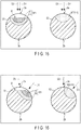
- FIG. 15 shows a first example of the first irradiation scar M1, second irradiation scar M2, and dent B, and shows a schematic cross-sectional view of the coil spring 2 at each of the first end 51 and second end 52.
- the cross section shown on the left side in FIG. 15 corresponds to the cross section of the first end 51 along line CA-CA in FIG. 14 .
- the cross section shown on the right side in FIG. 15 corresponds to the cross section of the second end 52 along line CB-CB in FIG. 14 .
- the upper surface in FIG. 15 is the outer circumferential surface 2a of the coil spring 2
- lower surface in FIG. 15 is the inner circumferential surface 2b of the coil spring 2.
- the broken line arrow in FIG. 15 indicates the irradiation direction D1 of the laser light at the time of heating.
- the solid line arrow indicates the moving direction D2 of the cutter 31 at the time of cutting.
- each of the irradiation direction D1 and moving direction D2 is the direction from the upper part in FIG. 15 to each end 51, 52. However, when the ends 51 and 52 are viewed from a direction different from the direction of the cross sections shown in FIG. 15 , these directions D1 and D2 may intersect each other.
- the first irradiation scar M1 includes the quench-hardened zone 1C and heat affected zone 1H. Further, the whole surface of the first irradiation scar M1 is overlapped with the dent B.
- the second irradiation scar M2 includes the heat affected zone 1H, and includes no quench-hardened zone 1C. Further, on the second end 52, no dent B is formed.
- Each of the first irradiation scar M1, second irradiation scar M2, and dent B is formed on the outer circumferential surface.
- FIG. 16 shows a second example of the first irradiation scar M1, second irradiation scar M2, and dent B, and shows a schematic cross-sectional view of the coil spring 2 at each of the first end 51 and second end 52 as in the case of FIG. 15 .
- the irradiation direction D1 forms an acute angle (for example 40°) with the moving direction D2.
- the first irradiation scar M1 includes a part thereof overlapping the dent B and part thereof not overlapping the dent B.
- the cutter 31 comes into contact with a hard part (base material) other than the heated portion 1V at the time of cutting, and hence it is possible to make the dent B less as compared with the first example.
- FIG. 17 shows a third example of the first irradiation scar M1, second irradiation scar M2, and dent B, and shows a schematic cross-sectional view of the coil spring 2 at each of the first end 51 and second end 52 as in the case of FIG. 15 .
- the irradiation direction D1 and moving direction D2 are directions opposite to each other.
- the first irradiation scar M1 and second irradiation scar M2 are formed on the inner circumferential surface 2b.
- the dent B is formed on the outer circumferential surface 2a.
- the cutter 31 does not come into contact with the heated portion 1V at the time of cutting, and hence the dent can be made further less as compared with the second example.
- the first irradiation scar M1, second irradiation scar M2, and dent B can be formed in various aspects.
- the dent B may be formed not only at the first end 51 but also at the second end 52.
- the dent B of the second end 52 may be less than the dent B of the first end 51.
- FIG. 18 is a schematic plan view of the wire 1 after being irradiated with the laser light having the shape shown in FIG. 6 .
- the irradiation center O of the laser light extends in the direction orthogonal to the axial direction of the wire 1. Accordingly, in the heated portion 1V formed by the irradiation of this laser light, the melt pool 1P (or quench-hardened zone 1C after solidification) has a shape elongated in the width direction of the wire 1.
- the heat affected zone 1H around the quench-hardened zone 1C has a shape elongated in the width direction of the wire 1.
- the heat affected zone 1H extends from one end to the other end of the wire 1 in the width direction thereof, the example is not limited to this.
- a distance D is provided between the irradiation center O and clearance center C by shifting the irradiation center O from the clearance center C to the cutter 31 side (left side in FIG. 18 ).
- the clearance center C is overlapped with the melt pool 1P.
- the end part 32a of the mandrel 32 is overlapped with a part of the heat affected zone 1H positioned on the upstream side of the melt pool 1P in the ⁇ -direction.
- the inventors of the present invention have carried out, a plurality of times, the experiment of cutting the wire 1 for each of the case where the irradiation center O and clearance center C are made overlapped with each other, case where the irradiation center O is shifted from the clearance center C to the cutter 31 side, and case where the irradiation center O is shifted from the clearance center C to the mandrel 32 side.
- the fracture surface of the case where the irradiation center O is shifted from the clearance center C to the cutter 31 side is the flattest
- fracture surface of the case where the irradiation center O and clearance center C are made overlapped with each other is the second flattest. From this result, it can be seen that by shifting the irradiation center O from the clearance center C to the cutter 31 side as in the case of this embodiment, the coil spring 2 having the flatter first end face 51a and flatter second end face 52a can be obtained.
- the heat affected zone 1H in the coil spring 2 manufactured by cutting the wire 1 under the condition of this embodiment, the heat affected zone 1H widely spreads in each of the first end face 51a and second end face 52a. In this case, the hardness of the heat affected zone 1H is lower as compared with the other parts, and hence the residual stress is reduced in this zone. Further, the above-described process of removing the residual stress can be omitted.
- the heat affected zone 1H spreads from one end of the wire 1 in the width direction thereof to the other end thereof.
- the heat affected zone 1H spreads over a wider range of the fracture surface. Accordingly, it is possible to more obviously obtain the effect of suppressing breakage of the end faces 51a and 52a.
- the configuration in which the coiling machine 100 cuts the heated portion 1V by means of the cutter 31 is exemplified.
- the coiling machine 100 is not limited to the configuration described above, and may cut the heated portion 1V of the wire 1 by a cutting operation using a rotary saw.
- the aspects of the coil springs 2 to be manufactured by the coiling machine 100 widely vary and, for example, the coil diameter and pitch may change in the axial direction of the coil spring. That is, the coil springs 2 to be manufactured by the coiling machine 100 may include coil springs of various aspects such as a cylindrical coil spring, barrel-type coil spring, hourglass-type coil spring, tapered coil spring, irregular-pitch coil spring, and coil spring including a negative-pitch part, and the like.
- Reference Signs List 1 ⁇ wire, 1V ⁇ heated portion, 1P ⁇ melt pool, 1C ⁇ quench-hardened zone, 1H ⁇ heat affected zone, 2 ⁇ coil spring, 10 ⁇ helix forming unit, 11 ⁇ driving roller, 12 ⁇ driven roller, 13 ⁇ wire guide, 14 ⁇ first forming roller, 15 ⁇ second forming roller, 16 ⁇ pitch tool, 20 ⁇ laser heating machine, 21 ⁇ laser oscillator, 22 ⁇ optical fiber, 23 ⁇ beam spot regulator, 24 ⁇ measuring instrument, 30 ⁇ cutting unit, 31 ⁇ cutter, 32 ⁇ mandrel, 40 ⁇ control unit, 41 ⁇ controller, 51 ⁇ first end, 51a ⁇ first end face, 52 ⁇ second end, 52a ⁇ second end face, 100 ⁇ coiling machine, L1, L2 ⁇ laser light, S01 ⁇ helix forming step, S02 ⁇ heating step, S03 ⁇ cutting step, M1 ⁇ first irradiation scar, M2 ⁇ Second irradiation scar
Landscapes
- Engineering & Computer Science (AREA)
- Mechanical Engineering (AREA)
- Physics & Mathematics (AREA)
- Optics & Photonics (AREA)
- Plasma & Fusion (AREA)
- Wire Processing (AREA)
- Springs (AREA)
- Particle Accelerators (AREA)
Abstract
Description
- Inventions described herein relate to a coiling machine configured to manufacture a coil spring, manufacturing method of a coil spring, and coil spring.
- As a device configured to manufacture a coil spring, for example, a coil spring forming machine described in
Patent Literature 1 is known. This coil spring forming machine calculates in advance a position of a cutting portion on the basis of a length of a wire to be formed into a helical shape, and cuts the wire at the cutting portion in a state where the cutting portion is softened by high-frequency heating. - On the other hand, as in the case of the spring manufacturing device described in
Patent Literature 2, a coiling machine configured to cut a wire formed into a helical shape by means of laser light is also known. -
- Patent Literature 1:
JP S62-50028 A - Patent Literature 2:
JP H06-218476 A - In the coil spring forming machine of
Patent Literature 1, the cutting portion is heated by high-frequency heating, and hence the responsiveness of heating of the cutting portion is not good. Moreover, cutting is carried out in the state where the cutting portion is continuously heated by high-frequency heating, and hence there is sometimes a case where the members used for cutting are adversely affected by the high-frequency heating. Furthermore, regarding the high-frequency heating, the responsiveness of heating of the cutting portion is not sufficient, and the wire is coiled in the state where the wire is partially heated, and hence there is a possibility of the forming accuracy of the spring becoming difficult to be maintained constant. - On the other hand, in the spring manufacturing device of
Patent Literature 2, high-power laser light capable of cutting a wire becomes necessary. In this case, a spatter resulting from laser light irradiation may occur, and laser light can possibly be applied to not only the wire, but also to various parts of the manufacturing device, and hence countermeasures should be taken against these problems. - Present inventions make it one of the objects to provide a coiling machine and manufacturing method of a coil spring making it possible to easily cut a wire formed into a helical shape, and to further provide a coil spring excellent in quality.
- A coiling machine according to the present invention includes a laser heating machine configured to irradiate a wire formed into a helical shape with laser light to thereby heat a part of the wire, and cutting components configured to cut a portion of the wire after the irradiation of the laser light is stopped, a temperature of the portion being higher than before irradiated with the laser light.
- A manufacturing method of a coil spring according to the present invention includes irradiating a wire formed into a helical shape with laser light to thereby heat a part of the wire, and cutting a portion of the wire after the irradiation of the laser light is stopped, a temperature of the portion being higher than before irradiated with the laser light.
- A coil spring according to the present invention is formed of a wire including a first end and a second end opposite to the first end, the first end includes a first irradiation scar of laser light, the first irradiation scar includes a quench-hardened zone the hardness of which is higher than a base material of the wire, and a first heat affected zone which is positioned around the quench-hardened zone and the hardness of which is lower than the base material, and the first heat affected zone extends to at least a part of an end face of the first end.
- According to the present invention, it is possible to provide a coiling machine and manufacturing method of a coil spring making it possible to easily cut a wire formed into a helical shape. Furthermore, according to the present invention, it is possible to provide a coil spring excellent in quality.
-
-
FIG. 1 is a schematic perspective view of a coiling machine according to a first embodiment. -
FIG. 2 is a schematic front view of the coiling machine ofFIG. 1 . -
FIG. 3 is a flowchart concerning an operation of the coiling machine according to the first embodiment. -
FIG. 4 is a schematic perspective view showing a process of forming a wire into a helical shape by the coiling machine according to the first embodiment. -
FIG. 5 is a schematic perspective view showing a process of softening a part of a wire by heating the part by means of a heating unit (laser heating machine). -
FIG. 6 is a perspective view showing a first example of the method of softening a part of a wire by heating. -
FIG. 7 is a cross-sectional view of the wire along VII-VII line ofFIG. 6 . -
FIG. 8 is a perspective view showing a second example of the method of softening a part of a wire by heating. -
FIG. 9 is a cross-sectional view of the wire along line IX-IX ofFIG. 8 . -
FIG. 10 is a schematic perspective view showing a process of cutting a wire by means of a cutting unit. -
FIG. 11 is a schematic cross-sectional view of a wire irradiated with laser light in a coiling machine according to a second embodiment. -
FIG. 12 is a cross-sectional view showing an example of appropriate positional relationships between a cutter, mandrel, and irradiated area irradiated with laser light. -
FIG. 13 is a cross-sectional view showing a state where a wire is cut by lowering the cutter from the state shown inFIG. 12 . -
FIG. 14 is a schematic side view of a coil spring cut off from the wire. -
FIG. 15 is a schematic cross-sectional view of a coil spring showing a first example of a first irradiation scar, second irradiation scar, and dent. -
FIG. 16 is a schematic cross-sectional view of a coil spring showing a second example of the first irradiation scar, second irradiation scar, and dent. -
FIG. 17 is a schematic cross-sectional view of a coil spring showing a third example of the first irradiation scar, second irradiation scar, and dent. -
FIG. 18 is a schematic plan view of a wire after being irradiated with laser light of a shape shown inFIG. 6 . - Some embodiments concerning a coiling machine, manufacturing method of a coil spring, and coil spring will be described below with reference to the accompanying drawings.
-
FIG. 1 is a schematic perspective view showing the main part of acoiling machine 100 according to a first embodiment.FIG. 2 is a schematic front view of thecoiling machine 100 ofFIG. 1 . The X-direction, Y-direction, Z-direction, and θ-direction are defined as shown inFIG. 1 andFIG. 2 . The X-direction, Y-direction, and Z-direction are orthogonal to each other. The X-direction is the wire-feeding direction. The Z-direction is the direction in which the helix of the coil spring is formed. The θ-direction is the direction in which a wire constituting the coil spring is wound. - The
coiling machine 100 includes ahelix forming unit 10, heating unit (laser heating machine 20),cutting unit 30, andcontrol unit 40. - The
helix forming unit 10 forms thewire 1 which is the material for the coil spring into a helical shape while feeding the wire thereto. Thehelix forming unit 10 described above includes a pair ofdriving rollers 11, a pair of drivenrollers 12,wire guide 13, first formingroller 14, second formingroller 15, andpitch tool 16. - Each of the
driving rollers 11 and each of the drivenrollers 12 are opposed to each other with a gap held between them. When each of thedriving rollers 11 rotates, each of the drivenrollers 12 is rotated through thewire 1. Thewire 1 pinched between eachdriving roller 11 and each drivenroller 12 is moved in the X-direction shown inFIG. 1 andFIG. 2 . Thewire 1 is inserted through thewire guide 13. Thewire guide 13 guides thewire 1 in such a manner that thewire 1 moves straight ahead in the X-direction to thereby lead thewire 1 to the first formingroller 14. - The first forming
roller 14, second formingroller 15, andpitch tool 16 are arranged in this order in the θ-direction and, when viewed from above, the order of their positions is different from the above in the Z-direction. The first formingroller 14 guides thewire 1 moving in the X-direction to the second formingroller 15 while bending thewire 1 into an arc-like shape and moving thewire 1 in the Y-direction shown inFIG. 1 . The second formingroller 15 guides thewire 1 moving forward in an arc-like shape to thepitch tool 16 while further bending thewire 1 into the arc-like shape. Thewire 1 guided by thepitch tool 16 moves in the Z-direction shown inFIG. 1 in a helically-formed state. - The
laser heating machine 20 radiates laser light in such a manner as to heat a part of thewire 1 formed into a helical shape. Owing to the irradiation of the laser light, aheated portion 1V the temperature of which is higher than the other portions is formed in thewire 1. Thelaser heating machine 20 described above includes alaser oscillator 21,optical fiber 22, and beam-spot regulator 23. - As the
laser oscillator 21, for example, a semiconductor laser configured to generate laser light can be used. Theoptical fiber 22 transmits the laser light generated by thelaser oscillator 21 to thebeam spot regulator 23. Thebeam spot regulator 23 modifies the beam shape of the laser light into a rectangular shape or circular shape. As thebeam spot regulator 23, for example, an optical element such as a beam homogenizer or the like can be used. - The
laser heating machine 20 may further include a measuringinstrument 24 configured to measure the temperature of theheated portion 1V. The measuringinstrument 24 includes, for example, a sensor configured to detect the temperature of theheated portion 1V of thewire 1. In order to avoid interference with the cuttingunit 30, the measuringinstrument 24 may be provided on the lateral side of the cuttingunit 30. In order to avoid interference with thecutter 31 to be described later, the measuringinstrument 30 can also be configured in such a manner as to move away from thecutter 31 in conjunction with the operation of thecutter 31. The measurement result obtained by the measuringinstrument 24 can be used for, for example, control of the timing for cutting thewire 1 to be carried out by the cuttingunit 30. - It should be noted that the measuring
instrument 24 is not an indispensable configuration. That is, various conditions concerning cutting of thewire 1 may be set in advance without using the measuringinstrument 24, and the cuttingunit 30 may cut theheated portion 1V on the basis of the conditions. - The
laser heating machine 20 may further include a migration stage configured to move thebeam spot regulator 23 closer to or away from theheated portion 1V of thewire 1. The migration stage can be constituted of, for example, a direct-acting stage or robot hand. When the operating distance of thebeam spot regulator 23 can be set sufficiently long or when the interference between thebeam spot regulator 23 and cuttingunit 30 can be avoided, there is no need to use the migration stage. - As shown in
FIG. 2 , the cuttingunit 30 cuts theheated portion 1V of thewire 1 the temperature of which is higher than before being irradiated with the laser light after the irradiation of the laser light is stopped. The cuttingunit 30 described above includes thecutter 31 andmandrel 32. - The
cutter 31 is arranged at a position between the second formingroller 15 andpitch tool 16, and above these members in the Y-direction. Thecutter 31 includes a sharp cutting blade the cutting edge of which is in the Z-direction at a tip thereof. Thecutter 31 is configured to be movable up and down in the Y-direction by means of a direct-acting stage not shown. Themandrel 32 is arranged inside the circular arc along which the first formingroller 14, second formingroller 15, andpitch tool 16 are arranged. The shape of themandrel 32 in the X-Y plane is semicircular as shown in, for example,FIG. 2 , and extends to elongate in the Z-direction. Themandrel 32 supports the inner circumferential surface of thewire 1 formed into the helical shape on the upper part of the circular arc surface thereof. - The
control unit 40 controls thehelix forming unit 10,laser heating machine 20, and cuttingunit 30. Thecontrol unit 40 described above includes acontroller 41. - The
controller 41 includes a read only memory (ROM), central processing unit (CPU), and random access memory (RAM). The ROM stores therein computer programs for controlling thehelix forming unit 10,laser heating machine 20, and cuttingunit 30. The CPU executes the computer programs stored in the ROM. The RAM temporarily stores therein, while the computer programs are executed by the CPU, various data items occurring concomitantly with the execution of the computer programs. - Subsequently, a manufacturing process of the
coil spring 2 using the coilingmachine 100 according to this embodiment will be described below with reference toFIGS. 3 to 10 . -
FIG. 3 is a flowchart concerning an operation of the coilingmachine 100. The operation shown by the flowchart is realized by thecontroller 41 by executing the computer programs. The manufacturing process of thecoil spring 2 to be carried out by the coilingmachine 100 includes a helix forming step S01, heating step S02, and cutting step S03. - In the helix forming step S01, the
wire 1 is formed into a helical shape. In the heating step S02 after the helix forming step S01 is completed, a part of thewire 1 is irradiated with laser light, whereby theheated portion 1V is formed in thewire 1. Theheated portion 1V includes a portion made softer than the other portions (base material) of thewire 1. In the cutting step S03 after the heating step S02 is completed, theheated portion 1V of thewire 1 is cut. -
FIG. 4 is a schematic perspective view of the coilingmachine 100 showing a specific example of the helix forming step S01. In the helix forming step S01, thehelix forming unit 10 makes thewire 1 move straight in the X-direction by means of the drivingrollers 11 and drivenrollers 12 to thereby lead thewire 1 to thewire guide 13. Thewire 1 output from thewire guide 13 is formed into an arc-like shape by the first formingroller 14 and second formingroller 15. Thewire 1 formed into the arc-like shape is guided by thepitch tool 16 in such a manner as to be formed into a helical shape having a predetermined pitch. Owing to such an operation, thehelical wire 1 is gradually elongated in the Z-direction. - With reference to
FIGS. 5 to 9 , the heating step S02 will be described below.FIG. 5 is a schematic perspective view of the coilingmachine 100 showing a specific example of the heating step S02. In the heating step S02, thelaser heating machine 20 directly irradiates, for example, the portion of thewire 1 formed into the helical shape positioned above (below the cutter 31) the end part of themandrel 32 with laser light. By the energy of the laser light, the base material of thewire 1 is heated and a softenedheated portion 1V is formed. - While the heating step S02 is executed, feeding of the
wire 1 carried out by thehelix forming unit 10 is stopped. Thelaser heating machine 20 is fixedly arranged at, for example, a predetermined position, and radiates laser light from this position toward a part of the stoppedwire 1. As another example, when thelaser heating machine 20 includes the above-described migration stage, thelaser heating machine 20 may radiate laser light after making thebeam spot regulator 23 close to thewire 1 as shown inFIG. 5 . Further, the action of thelaser heating machine 20 may also be controlled in such a manner that while the heating step S02 is executed, feeding of thewire 1 carried out by thehelix forming unit 10 is not stopped, and the laser light irradiation position moves to follow the movement of the cutting position resulting from the coiling operation. -
FIG. 6 is a perspective view showing a first example of the method of softening a part of thewire 1 by heating. Thelaser heating machine 20 irradiates the surface of thewire 1 with laser light L1. The laser light L1 has a beam profile elongated in the width direction of thewire 1. In theirradiated area 1a of thewire 1 irradiated with the laser light L1 and surrounding part thereof, aheated portion 1V is formed. -
FIG. 7 is a cross-sectional view of thewire 1 along line VII-VII inFIG. 6 . Theheated portion 1V extends not only to the surrounding part of theirradiated area 1a on the surface of thewire 1, but also to the inside of thewire 1. In the example ofFIG. 7 , the width WD1 of the laser light L1 in the width direction of thewire 1 is less than the diameter R of thewire 1. Accordingly, the most part of the laser light L1 is applied to thewire 1. -
FIG. 8 is a perspective view of thewire 1 showing a second example of the method of softening a part of thewire 1 by heating. Thelaser heating machine 20 irradiates the surface of thewire 1 with laser light L2. The laser light L2 has a beam profile of, for example, a circular shape. In theirradiated area 1a of thewire 1 irradiated with the laser light L2 and surrounding part thereof, aheated portion 1V is formed as in the case of the first example. -
FIG. 9 is a cross-sectional view of thewire 1 along line IX-IX inFIG. 8 . Theheated portion 1V extends not only to the surrounding part of theirradiated area 1a on the surface of thewire 1, but also to the inside of thewire 1. For example, the width WD2 of the laser light L2 is sufficiently less than the diameter R of thewire 1. Accordingly, the most part of the laser light L2 is applied to thewire 1. - It should be noted that although in each of the examples of
FIGS. 6 to 9 , the laser light L1 or L2 parallel to the Y-direction is applied to the top surface of thewire 1 in the Y-direction, the irradiation direction of the laser light L1 or L2 is not limited to this. For example, the laser light L1 or L2 may also be applied to thewire 1 from the direction intersecting the Y-direction. Further, the laser light L1 or L2 may also be applied to the undersurface of thewire 1 in the Y-direction. - The
heated portion 1V may extend to a position deeper inside thewire 1 than the examples shown inFIG. 7 andFIG. 9 . The shape of the laser light emitted from thelaser heating machine 20 is not limited to the first example and second example. The laser light may be applied to only one portion of thewire 1 or may be applied to a plurality of portions thereof. - In both the first example and second example, the
heated portion 1V may include a melt pool formed by melting the base material of thewire 1 by the energy of the laser light. In this case, the melt pool may spread not only to parts inside theirradiated area 1a but also to the surrounding part thereof. - The cutting step S03 will be described below with reference to
FIG. 10. FIG. 10 is a schematic perspective view of the coilingmachine 100 showing a specific example of the cutting step S03. The cutting step S03 is executed after the laser light irradiation is stopped. In the cutting step S03, theheated portion 1V of thewire 1 the temperature of which has become higher than before being irradiated with the laser light is cut by the cuttingunit 30. Thereby, thecoil spring 2 is manufactured. - More specifically, in the cutting step S03, the
cutter 31 is made to descend toward the vicinity of the part of thewire 1 supported on themandrel 32. At this time, thewire 1 is cut by the impact applied thereto by thecutter 31. - When the
heated portion 1V includes a melt pool, the melt pool may solidify within the time when the laser light irradiation is stopped to the time when thecutter 31 operates. Further, the melt pool may solidify after the cutter starts to operate, and when thecutter 31 comes into contact with the surface of thewire 1 to thereby draw heat from theheated portion 1V. As described above, the melt pool solidifies before or during the operation of thecutter 31, whereby it is possible to prevent the molten metal from adhering to thecutter 31. - It is also possible, in the cutting step S03, to operate the
cutter 31 on the basis of a result of measurement of the temperature of theheated portion 1V carried out by the measuringinstrument 24. That is, thecutter 31 may operate after the laser light irradiation is stopped and, when the temperature of theheated portion 1V lowers to a predetermined target temperature. The above-described target temperature may be, for example, the temperature at which the molten base material solidifies. Of course, in the cutting step S03, theheated portion 1V may be cut without using the measuringinstrument 24 by determining in advance a delay time from the stop of laser light irradiation to the start of the operation of thecutter 31. - The cut-off
coil spring 2 has afirst end 51 including afirst end face 51a, andsecond end 52 including asecond end face 52a. After onecoil spring 2 is manufactured, the above-described helix forming step S01, heating step S02, and cutting step S03 are executed again, and then thenext coil spring 2 is manufactured. Accordingly, both thefirst end 51 andsecond end 52 are formed by cutting after the above-described steps are carried out. - The shearing force required to cut the wire decreases with the raise in temperature of the wire resulting from heating. Further, even when the temperature of the wire does not reach the melting point, it is possible to reduce the shearing force. Furthermore, such a tendency described above is independent of the diameter of the wire. As one example, it is desirable that when the
wire 1 is about to be cut by thecutter 31, the temperature of at least a part of theheated portion 1V be higher than or equal to 500°C. - Subsequently, the advantageous effects of the coiling
machine 100 and manufacturing method of acoil spring 2 according to this embodiment will be described below. In this embodiment, a part of thewire 1 formed into a helical shape is heated by laser light, and the portion (heated portion 1V) the temperature of which is higher than before being irradiated with the laser light after the irradiation of the laser light is stopped is cut by the cutting components (cutter 31 and mandrel 32). When thewire 1 is heated, the shearing force required for cutting becomes less. Therefore, according to this embodiment, it is possible to easily cut thewire 1. - When the
laser heating machine 20 is used as in the case of this embodiment, it is possible to selectively and rapidly heat the portion to be cut by means of laser light. When thelaser heating machine 20 is used, it is possible to arbitrarily set the heat input amount of heat to be input to the portion to be irradiated with laser light by adjusting the drive current of thelaser oscillator 21. Further, it is possible to increase/decrease the output of the laser light by making a quick response to the adjustment of the drive current. Furthermore, it is possible to make theheated portion 1V carry out rapid self-cooling by stopping the laser light irradiation carried out by thelaser heating machine 20. It should be noted that the term 'rapid self-cooling' implies that theheated portion 1V is rapidly cooled without aggressively cooling theheated portion 1V by using members and devices for cooling. Further, it is possible for thelaser heating machine 20 to arbitrarily set theirradiated area 1a to be irradiated with the laser light andheated portion 1V of thewire 1 by adjusting the irradiation angle of the laser light relative to thewire 1 or by using a lens or mirror. Accordingly, it is possible for thelaser heating machine 20 to heat an arbitrary area of thewire 1 to an arbitrary temperature with a high degree of responsiveness in accordance with the thickness of thewire 1, material for thewire 1, required takt time (cycle time), and the like. - Further, according to the configuration of this embodiment, the
heated portion 1V in the state where theportion 1V is softened by the high temperature is cut, whereby the reaction force received by thecutter 31 andmandrel 32 from thewire 1 at the time of cutting is reduced. Accordingly, it is possible to suppress wear and tear of thecutter 31 andmandrel 32, and damage to these members. As a result, it is possible to make the replacement cycle of thecutter 31 ormandrel 32 longer than ever before and thereby reduce the running cost, and to lower the specification of abrasion resistance property or the like required of the materials for thecutter 31 andmandrel 32 and thereby form these members at lower costs than ever before. Further, it is possible to suppress lowering of the operating rate of the coilingmachine 100 concomitant with the replacement of thecutter 31 andmandrel 32. - Further, according to the configuration of this embodiment, even when a
wire 1 having a relatively large diameter is used, it is possible to cut thewire 1 without excessively increasing the time required for cutting of thewire 1. Furthermore, regarding the coilingmachine 100, even when awire 1 having a relatively large diameter is used, it is not necessary to impart a relatively higher capability to thecutter 31 andmandrel 32. Accordingly, even when awire 1 having a relatively large diameter is used, it is possible to maintain the mass-productivity, and suppress the cost required for thecutter 31 andmandrel 32. - Further, in this embodiment, the
wire 1 is not cut by using only the laser light irradiation, thewire 1 is cut by further using thecutter 31. According to such a configuration, it is possible to suppress the required intensity of the laser light. That is, thelaser heating machine 20 radiates laser light not for the purpose of cutting thewire 1 but for the purpose of softening thewire 1, whereby it is possible to make the intensity of the laser light lower as compared with the case where thewire 1 is cut by only the laser light. As a result, it is possible to suppress occurrence of the spatter and dross which can occur when thewire 1 is irradiated with laser light of high intensity, and make the facilities and cost for assist gas blowing unnecessary. Accordingly, it is possible to increase the operating rate of the coilingmachine 100 by keeping the cleanliness of thecoil spring 2 to be manufactured and thereby making washing thereof unnecessary, and by reducing the maintenance work concerning removal of the spatter adhering to the coilingmachine 100 itself. Furthermore, it is possible to simplify or decommission the facilities such as a suction device or the like necessary for removal of the spatter. - Further, according to the configuration of this embodiment, it is possible to limit the irradiation range of the laser light relative to the
wire 1. That is, thelaser heating machine 20 radiates laser light not for the purpose of cutting thewire 1 but for the purpose of softening thewire 1, and hence thelaser heating machine 20 need not necessarily irradiate the entire area of the position scheduled to be cut and, it is sufficient if thelaser heating machine 20 can irradiate a part of thewire 1 in the width direction with laser light as shown in, for example,FIGS. 6 to 9 . More specifically, it is possible for thelaser heating machine 20 to irradiate the central part of thewire 1 with laser light while avoiding both the end parts of thewire 1 in the width direction thereof. In this case, even when the position to be irradiated with laser light is shifted from the correct position relatively to thewire 1, it is possible to prevent the laser light from extending out of both the end parts of thewire 1 to thereby cause a shortage of the amount of laser light irradiation to be applied to thewire 1 or to thereby thermally and adversely affect the coilingmachine 100 itself. - Further, it is possible to prevent the laser light to be applied to the
wire 1 from leaking from the opposite side of thewire 1. That is, thelaser heating machine 20 radiates laser light not for the purpose of cutting thewire 1 but for the purpose of softening thewire 1, and hence thelaser heating machine 20 need not radiate laser light in such a manner as to penetrate and split up thewire 1. Accordingly, it is possible to largely simplify or decommission the configuration for shielding the laser light as compared with the conventional coiling machine configured to cut the wire by means of laser light. - Further, according to the configuration of this embodiment, in particular, when the
wire 1 after being formed into a helical shape by cold working is heated and cut, it is possible to maintain the shape accuracy of thecoil spring 2 higher as compared with the case of warm working. - Assuming that the
wire 1 is cut by only laser light, it is necessary to relatively enhance the intensity of the laser light, and hence it is difficult to form thefirst end face 51a andsecond end face 52a flat. Further, when thewire 1 is cut by only the cutter without using laser light, it is necessary to apply strong shearing force to thewire 1, and hence large unevenness is liable to occur on each of the end faces 51a and 52a. Conversely, in this embodiment, thewire 1 is cut not only by means of laser light irradiation, but also by means of thecutter 31, and thus it is possible to make the intensity of the laser light lower, and make the shearing force of thecutter 31 less, whereby it becomes possible to form the end faces 51a and 52a flat. As a result, it is possible to obtain acoil spring 2 excellent in quality. - As described above, when the
heated portion 1V is at least partially heated to a temperature higher than or equal to 500°C at the time of cutting by thecutter 31, it is possible to cut thewire 1 in the high-temperature solid state where theheated portion 1V is sufficiently softened (working resistance of thewire 1 is sufficiently reduced). Regarding carbon steel to be generally used as a material for thewire 1, by heating the steel to a temperature higher than or equal to about 500°C, the tensile strength (TS) thereof becomes about half the TS at normal temperature or less, and it is possible to easily cut the steel by thecutter 31. - As described above, when a melt pool is formed at the
heated portion 1V, it is possible to make theheated portion 1V extend to a position deep inside thewire 1. Thereby, thewire 1 is softened up to the part thereof deep inside, and cutting of thewire 1 by thecutter 31 is further facilitated. - In addition to the above, various appropriate effects can be obtained from this embodiment.
- A second embodiment will be described below. In this embodiment, appropriate conditions for cutting the
wire 1 by using the above-describedcoiling machine 100 will mainly be disclosed. The configuration of the coiling machine and flow of the manufacturing method of the coil spring using the coilingmachine 100 are identical to the first embodiment. -
FIG. 11 is a schematic cross-sectional view of thewire 1 irradiated with laser light. Here, the case where the surface of thewire 1 is irradiated with laser light (L2) having a shape shown inFIG. 8 , and melt pool is formed is assumed. Here, O inFIG. 11 indicates the center of the irradiated area irradiated with the laser light on the outer circumferential surface of thewire 1. As an example, this irradiation center O corresponds to a position irradiated with the peak part of the beam profile of the laser light having the highest intensity. Further, it is also possible to consider the irradiation center O as the center of the melt pool. - As described above, when the
wire 1 is irradiated with the laser light, theheated portion 1V is formed. During irradiation of the laser light or immediately after irradiation of the laser light, a melt pool is formed around the irradiation center O. The melt pool is solidified by subsequent cooling and a quench-hardenedzone 1C is formed. Around the melt pool, a heat-affected zone (HAZ) 1H which is not melted but is changed to be different in characteristics from the base material of thewire 1 by the heat at the time of laser light irradiation is formed. As described above, theheated portion 1V includes the quench-hardenedzone 1C and heat affectedzone 1H. - In
FIG. 11 , a result of measuring the Vickers hardness as to each of the quench-hardenedzone 1C, heat affectedzone 1H, and base material of thewire 1 is shown. The quench-hardenedzone 1C as a whole has higher hardness as compared with the base material. On the other hand, the heat affectedzone 1H as a whole has lower hardness as compared with the base metal.
The hardness of the heat affectedzone 1H gradually becomes higher from the vicinity of the quench-hardenedzone 1C toward the base material. - As described above, in the
heated portion 1V, the distribution of hardness is not uniform. Accordingly, it is necessary to appropriately determine the positional relationships between the positions of thecutter 31 andmandrel 32, and irradiated area irradiated with laser light. -
FIG. 12 is cross-sectional view showing an example of appropriate positional relationships between thecutter 31,mandrel 32, and irradiated area irradiated with laser light. In the above-described helix forming step S01, thewire 1 formed into the helical shape is fed to a position between thecutter 31 andmandrel 32. In the feed direction (θ-direction) of thewire 1, between theend part 31a of the cutter and endpart 32a of themandrel 32, a clearance G is provided. Hereinafter, the center of the clearance G in the θ-direction is referred to as the clearance center C. - In the example of
FIG. 12 , the clearance center C and irradiation center O are shifted from each other in the θ-direction. More specifically, the irradiation center O is positioned on thecutter 31 side (downstream side in the θ-direction) of the clearance center C. - In the example of
FIG. 12 , theheated portion 1V includes themelt pool 1P which becomes the quench-hardenedzone 1C after solidification. For example, themelt pool 1P and clearance center C are overlapped with each other. Further, themelt pool 1P is overlapped with theend part 31a of thecutter 31 when viewed from the Y-direction. - On the other hand, the
melt pool 1P is not overlapped with theend part 32a of themandrel 32 when viewed from the Y-direction. In the example ofFIG. 12 , theend part 32a of themandrel 32 and a part of the heat affectedzone 1H positioned on the upstream side of themelt pool 1P overlap each other when viewed from the Y-direction. -
FIG. 13 is a cross-sectional view showing a state where thewire 1 is cut by lowering thecutter 31 in the Y-direction from the state shown inFIG. 12 . As described above, whenwire 1 is cut by thecutter 31, themelt pool 1P is already solidified or themelt pool 1P is solidified by being deprived of heat thereof by the contact with thecutter 31. Accordingly, while thewire 1 is cut, the quench-hardenedzone 1C is already formed. It should be noted that when thewire 1 to be cut, part of themelt pool 1P may remain inside theheated portion 1V. - When the tip part of the
cutter 31 applies an impact to the outer circumferential surface of a part of thewire 1 protruding from theend part 32a of themandrel 32, shearing force is applied to theheated portion 1V and surrounding par thereof, whereby thewire 1 is broken at around theportion 1V. The cutter lowers to, for example, a position close to the axis of thewire 1 at the maximum. On thecut wire 1, i.e., on thecoil spring 2, a dent B attributable to thecutter 31 is formed. Although in the example ofFIG. 13 , the quench-hardenedzone 1C and heat affected zone are overlapped with the dent B, they may be shifted from each other. - As described above, the heat affected
zone 1H is lower in hardness than the quench-hardenedzone 1C and base material of thewire 1. Accordingly, when thecutter 31 applies an impact to thewire 1, in theheated portion 1V, the heat affectedzone 1H is susceptible to fracture. In particular, when the irradiation center O is shifted from the clearance center C to thecutter 31 side as shown inFIG. 12 , it is possible to effectively apply the burden to a part of the heat affectedzone 1H positioned on the upstream side of themelt pool 1P in the θ-direction and thereby fracture thewire 1 at this part. -
FIG. 14 is a schematic side view of thecoil spring 2 cut off from thewire 1 by the method shown inFIG. 12 andFIG. 13 . Thecoil spring 2 has thefirst end 51 including thefirst end face 51a, andsecond end 52 including thesecond end face 52a. - The
first end face 51a corresponds to a fracture surface of thecoil spring 2 cut off from thewire 1 inFIG. 13 . Thefirst end 51 includes a first irradiation scar M1 of the laser light and dent B of thecutter 31. The first irradiation scar M1 includes the quench-hardenedzone 1C and heat affectedzone 1H (first heat affected zone). - The
second end face 52a corresponds to the fracture surface of thewire 1 left on themandrel 32 when thecoil spring 2 manufactured before thecurrent coil spring 2 is cut off from thewire 1. Thesecond end 52 includes a second irradiation scar M2 of the laser light. The second irradiation scar M2 includes the heat affectedzone 1H (second heat affected zone). When thewire 1 is cut as shown inFIG. 13 , the second irradiation scar M2 includes no quench-hardenedzone 1C. However, the second irradiation scar M2 may include, for example, a quench-hardenedzone 1C less than the first irradiation scar M1. - The heat affected
zone 1H included in the first irradiation scar M1 extends to at least a part of thefirst end face 51a. Further, the heat affectedzone 1H included in the second irradiation scar M2 extends to at least a part of thesecond end face 52a. On the other hand, the quench-hardenedzone 1C included in the first irradiation scar M1 does not extend to thefirst end face 51a. However, a part of the quench-hardenedzone 1C may extend to thefirst end face 51a. In this case, it is desirable that the area of the quench-hardenedzone 1C be less than the area of the heat affectedzone 1H in thefirst end face 51a. - Subsequently, regarding the positional relationships between the first irradiation scar M1, second irradiation scar M2, and dent B, some aspects will be exemplified.
-
FIG. 15 shows a first example of the first irradiation scar M1, second irradiation scar M2, and dent B, and shows a schematic cross-sectional view of thecoil spring 2 at each of thefirst end 51 andsecond end 52. The cross section shown on the left side inFIG. 15 corresponds to the cross section of thefirst end 51 along line CA-CA inFIG. 14 . The cross section shown on the right side inFIG. 15 corresponds to the cross section of thesecond end 52 along line CB-CB inFIG. 14 . In each of thefirst end 51 andsecond end 52, the upper surface inFIG. 15 is the outercircumferential surface 2a of thecoil spring 2, and lower surface inFIG. 15 is the innercircumferential surface 2b of thecoil spring 2. - The broken line arrow in
FIG. 15 indicates the irradiation direction D1 of the laser light at the time of heating. The solid line arrow indicates the moving direction D2 of thecutter 31 at the time of cutting. In the example ofFIG. 15 , each of the irradiation direction D1 and moving direction D2 is the direction from the upper part inFIG. 15 to eachend FIG. 15 , these directions D1 and D2 may intersect each other. - In the
first end 51 shown on the left side inFIG. 15 , the first irradiation scar M1 includes the quench-hardenedzone 1C and heat affectedzone 1H. Further, the whole surface of the first irradiation scar M1 is overlapped with the dent B. In thesecond end 52 shown on the right side inFIG. 15 , the second irradiation scar M2 includes the heat affectedzone 1H, and includes no quench-hardenedzone 1C. Further, on thesecond end 52, no dent B is formed. Each of the first irradiation scar M1, second irradiation scar M2, and dent B is formed on the outer circumferential surface. -
FIG. 16 shows a second example of the first irradiation scar M1, second irradiation scar M2, and dent B, and shows a schematic cross-sectional view of thecoil spring 2 at each of thefirst end 51 andsecond end 52 as in the case ofFIG. 15 . In the example ofFIG. 16 , the irradiation direction D1 forms an acute angle (for example 40°) with the moving direction D2. Accordingly, in thefirst end 51, the first irradiation scar M1 includes a part thereof overlapping the dent B and part thereof not overlapping the dent B. In the case of such a configuration, thecutter 31 comes into contact with a hard part (base material) other than theheated portion 1V at the time of cutting, and hence it is possible to make the dent B less as compared with the first example. -
FIG. 17 shows a third example of the first irradiation scar M1, second irradiation scar M2, and dent B, and shows a schematic cross-sectional view of thecoil spring 2 at each of thefirst end 51 andsecond end 52 as in the case ofFIG. 15 . In the example ofFIG. 17 , the irradiation direction D1 and moving direction D2 are directions opposite to each other. The first irradiation scar M1 and second irradiation scar M2 are formed on the innercircumferential surface 2b. The dent B is formed on the outercircumferential surface 2a. At thefirst end 51, the whole of the first irradiation scar M1 is not overlapped with the dent B. In the case of such a configuration, thecutter 31 does not come into contact with theheated portion 1V at the time of cutting, and hence the dent can be made further less as compared with the second example. - In addition to the above, the first irradiation scar M1, second irradiation scar M2, and dent B can be formed in various aspects. For example, the dent B may be formed not only at the
first end 51 but also at thesecond end 52. In this case, the dent B of thesecond end 52 may be less than the dent B of thefirst end 51. - It should be noted that although up to this point, the case where the
wire 1 is irradiated with the laser light (L2) having the shape shown inFIG. 8 is assumed, the same configuration as above can be applied to the case where thewire 1 is irradiated with the laser light (L1) having the shape shown inFIG. 6 . -
FIG. 18 is a schematic plan view of thewire 1 after being irradiated with the laser light having the shape shown inFIG. 6 . The irradiation center O of the laser light extends in the direction orthogonal to the axial direction of thewire 1. Accordingly, in theheated portion 1V formed by the irradiation of this laser light, themelt pool 1P (or quench-hardenedzone 1C after solidification) has a shape elongated in the width direction of thewire 1. Likewise, the heat affectedzone 1H around the quench-hardenedzone 1C has a shape elongated in the width direction of thewire 1. Although in the example ofFIG. 18 , the heat affectedzone 1H extends from one end to the other end of thewire 1 in the width direction thereof, the example is not limited to this. - When the
wire 1 on which such aheated portion 1V is formed is cut, a distance D is provided between the irradiation center O and clearance center C by shifting the irradiation center O from the clearance center C to thecutter 31 side (left side inFIG. 18 ). In the example ofFIG. 18 , the clearance center C is overlapped with themelt pool 1P. Further, theend part 32a of themandrel 32 is overlapped with a part of the heat affectedzone 1H positioned on the upstream side of themelt pool 1P in the θ-direction. - When the
wire 1 is cut by means of thecutter 31 in this state, as in the case ofFIG. 12 andFIG. 13 , it is possible to apply the shearing force to a part of the heat affectedzone 1H positioned on the upstream side of themelt pool 1P in the θ-direction and fracture this part. - As described above, in this embodiment, by shifting the irradiation center O and clearance center C from each other, it is possible to fracture the
wire 1 at the heat affectedzone 1H the hardness of which is less as compared with the other parts. In this case, it is possible to make the shearing force needed to cut thewire 1 less as compared with, for example, the case where thewire 1 is fractured at the quench-hardenedzone 1C. - It should be noted that the inventors of the present invention have carried out, a plurality of times, the experiment of cutting the
wire 1 for each of the case where the irradiation center O and clearance center C are made overlapped with each other, case where the irradiation center O is shifted from the clearance center C to thecutter 31 side, and case where the irradiation center O is shifted from the clearance center C to themandrel 32 side. As a result, the fracture surface of the case where the irradiation center O is shifted from the clearance center C to thecutter 31 side is the flattest, and fracture surface of the case where the irradiation center O and clearance center C are made overlapped with each other is the second flattest. From this result, it can be seen that by shifting the irradiation center O from the clearance center C to thecutter 31 side as in the case of this embodiment, thecoil spring 2 having the flatterfirst end face 51a and flattersecond end face 52a can be obtained. - When the
wire 1 is formed into a helical shape and the helically formedwire 1 is cut by means of thecutter 31, a certain amount of residual stress occurs at each of thefirst end face 51a andsecond end face 52a of thecoil spring 2. Such residual stress becomes a cause of breakage of the end faces 51a and 52a. Further, when thecoil spring 2 is made to undergo a process of energizing thecoil spring 2 to thereby cause a temperature rise thereof, the residual stress can be removed. However, in this method, the temperatures of both the ends of thecoil spring 2 hardly rise, and hence various contrivances should be made. - Regarding this point, in the
coil spring 2 manufactured by cutting thewire 1 under the condition of this embodiment, the heat affectedzone 1H widely spreads in each of thefirst end face 51a andsecond end face 52a. In this case, the hardness of the heat affectedzone 1H is lower as compared with the other parts, and hence the residual stress is reduced in this zone. Further, the above-described process of removing the residual stress can be omitted. - In the example shown in
FIG. 18 , the heat affectedzone 1H spreads from one end of thewire 1 in the width direction thereof to the other end thereof. In this case, the heat affectedzone 1H spreads over a wider range of the fracture surface. Accordingly, it is possible to more obviously obtain the effect of suppressing breakage of the end faces 51a and 52a. - It should be noted that it is needless to say that in implementing the present invention, the aspects of the configurations and arrangements of the elements provided in the coiling
machine 100 can variously be changed as the need arises to thereby implement the present invention. - In each of the embodiments, the configuration in which the coiling
machine 100 cuts theheated portion 1V by means of thecutter 31 is exemplified. The coilingmachine 100 is not limited to the configuration described above, and may cut theheated portion 1V of thewire 1 by a cutting operation using a rotary saw. - The aspects of the
coil springs 2 to be manufactured by the coilingmachine 100 widely vary and, for example, the coil diameter and pitch may change in the axial direction of the coil spring. That is, thecoil springs 2 to be manufactured by the coilingmachine 100 may include coil springs of various aspects such as a cylindrical coil spring, barrel-type coil spring, hourglass-type coil spring, tapered coil spring, irregular-pitch coil spring, and coil spring including a negative-pitch part, and the like. Reference Signs List
1 ··· wire, 1V ··· heated portion, 1P ··· melt pool, 1C ··· quench-hardened zone, 1H ··· heat affected zone, 2 ··· coil spring, 10 ··· helix forming unit, 11 ··· driving roller, 12 ··· driven roller, 13 ··· wire guide, 14 ··· first forming roller, 15 ··· second forming roller, 16 ··· pitch tool, 20 ··· laser heating machine, 21 ··· laser oscillator, 22 ··· optical fiber, 23 ··· beam spot regulator, 24 ··· measuring instrument, 30 ··· cutting unit, 31 ··· cutter, 32 ··· mandrel, 40 ··· control unit, 41 ··· controller, 51 ··· first end, 51a ··· first end face, 52 ··· second end, 52a ··· second end face, 100 ··· coiling machine, L1, L2 ··· laser light, S01 ··· helix forming step, S02 ··· heating step, S03 ··· cutting step, M1 ··· first irradiation scar, M2 ··· Second irradiation scar, and B ··· dent.
Claims (16)
- A coiling machine comprising:a laser heating machine configured to irradiate a wire formed into a helical shape with laser light to thereby heat a part of the wire; andcutting components configured to cut a portion of the wire after the irradiation of the laser light is stopped, a temperature of the portion being higher than before irradiated with the laser light.
- The coiling machine of claim 1, wherein
the cutting components cut the portion of the wire heated to a temperature higher than or equal to 500°C. - The coiling machine of claim 1, whereinthe laser heating machine irradiates the wire with the laser light to thereby form a melt pool and a heat affected zone around the melt pool in the wire, andthe cutting components cut the heat affected zone of the wire.
- The coiling machine of claim 1, wherein
the cutting components include:a mandrel configured to support thereon an inner circumferential surface of the wire formed into a helical shape; anda cutter configured to apply an impact to an outer circumferential surface of a part of the wire protruding from an end part of the mandrel to thereby cut the wire. - The coiling machine of claim 4, whereina clearance is provided between the cutter and the end part of the mandrel in a feed direction of the wire, andwhen the cutter applies an impact to the wire, a center of the clearance and a center of an irradiated area irradiated with the laser light on the wire are shifted from each other in the feed direction.
- The coiling machine of claim 5, wherein
the center of the irradiated area is positioned on the cutter side of the center of the clearance in the feed direction. - The coiling machine of claim 6, whereinthe laser heating machine irradiates the wire with the laser light to thereby form a melt pool and a heat affected zone around the melt pool in the wire, andwhen the cutter applies an impact to the wire, the end part of the mandrel and a part of the heat affected zone positioned on the upstream side of the melt pool in the feed direction are overlapped with each other when viewed from a moving direction of the cutter.
- A manufacturing method of a coil spring comprising:irradiating a wire formed into a helical shape with laser light to thereby heat a part of the wire; andcutting a portion of the wire after the irradiation of the laser light is stopped, a temperature of the portion being higher than before irradiated with the laser light.
- The manufacturing method of a coil spring of claim 8, wherein
when the portion of the wire is to be cut, the portion is already heated to a temperature higher than or equal to 500°C. - The manufacturing method of a coil spring of claim 8, further comprising:feeding the wire formed into a helical shape to a position between a mandrel configured to support thereon an inner circumferential surface of the wire formed into the helical shape and a cutter; andapplying, when the wire is to be cut, an impact to an outer circumferential surface of a part of the wire protruding from an end part of the mandrel.
- The manufacturing method of a coil spring of claim 10, whereina clearance is provided between the cutter and the end part of the mandrel in a feed direction of the wire, andwhen the cutter applies an impact to the wire, a center of the clearance and a center of an irradiated area irradiated with the laser light on the wire are shifted from each other in the feed direction.
- The manufacturing method of a coil spring of claim 11, wherein
the center of the irradiated area is positioned on the cutter side of the center of the clearance in the feed direction. - The manufacturing method of a coil spring of claim 12, whereinthe wire is irradiated with the laser light, whereby a melt pool and a heat affected zone around the melt pool are formed in the wire, andwhen the cutter applies an impact to the wire, the end part of the mandrel and a part of the heat affected zone positioned on the upstream side of the melt pool in the feed direction are overlapped with each other when viewed from a moving direction of the cutter.
- A coil spring formed of a wire including a first end and a second end opposite to the first end, whereinthe first end includes a first irradiation scar of laser light,the first irradiation scar includes a quench-hardened zone the hardness of which is higher than a base material of the wire, and a first heat affected zone which is positioned around the quench-hardened zone and the hardness of which is lower than the base material, andthe first heat affected zone extends to at least a part of an end face of the first end.
- The coil spring of claim 14, whereinthe second end includes a second irradiation scar of laser light smaller than the first irradiation scar,the second irradiation scar includes a second heat affected zone the hardness of which is lower than the base material, andthe second heat affected zone extends to at least a part of an end face of the second end.
- The coil spring of claim 14, wherein
the first end includes a dent overlapped with the first irradiation scar on the outer circumferential surface.
Applications Claiming Priority (2)
| Application Number | Priority Date | Filing Date | Title |
|---|---|---|---|
| JP2019019754 | 2019-02-06 | ||
| PCT/JP2019/046219 WO2020161998A1 (en) | 2019-02-06 | 2019-11-26 | Coiling machine, method for manufacturing coil spring, and coil spring |
Publications (3)
| Publication Number | Publication Date |
|---|---|
| EP3922377A1 true EP3922377A1 (en) | 2021-12-15 |
| EP3922377A4 EP3922377A4 (en) | 2022-10-26 |
| EP3922377B1 EP3922377B1 (en) | 2025-01-22 |
Family
ID=71947068
Family Applications (1)
| Application Number | Title | Priority Date | Filing Date |
|---|---|---|---|
| EP19914558.2A Active EP3922377B1 (en) | 2019-02-06 | 2019-11-26 | Coiling machine, method for manufacturing coil spring, and coil spring |
Country Status (7)
| Country | Link |
|---|---|
| US (1) | US20210362274A1 (en) |
| EP (1) | EP3922377B1 (en) |
| JP (3) | JP7066880B2 (en) |
| CN (1) | CN113365755B (en) |
| HU (1) | HUE070750T2 (en) |
| MX (1) | MX2021008990A (en) |
| WO (1) | WO2020161998A1 (en) |
Families Citing this family (6)
| Publication number | Priority date | Publication date | Assignee | Title |
|---|---|---|---|---|
| JP7203910B1 (en) * | 2021-07-01 | 2023-01-13 | 日本発條株式会社 | Coil spring, suspension, and method for manufacturing coil spring |
| CN113857394B (en) * | 2021-09-22 | 2024-10-15 | 安徽环新集团股份有限公司 | Piston ring blank coiling machine |
| CN114898947B (en) * | 2022-05-10 | 2024-02-09 | 江苏欣达通信科技股份有限公司 | Spring type jumper wire machining equipment and machining method |
| JP7840814B2 (en) * | 2022-08-15 | 2026-04-06 | 日本発條株式会社 | Coiling machine and method for manufacturing coil springs |
| JP7840815B2 (en) | 2022-08-15 | 2026-04-06 | 日本発條株式会社 | Coiling machine and method for manufacturing coil springs |
| JP7749872B1 (en) * | 2025-04-10 | 2025-10-06 | 日本発條株式会社 | Coiling machine and coil spring manufacturing method |
Family Cites Families (19)
| Publication number | Priority date | Publication date | Assignee | Title |
|---|---|---|---|---|
| US2995648A (en) * | 1958-08-11 | 1961-08-08 | Staples & Company Ltd | Spring coiling apparatus |
| GB1374915A (en) * | 1971-03-08 | 1974-11-20 | Hattan M Green W P | Formation of nuts |
| JPS6250028A (en) | 1985-08-27 | 1987-03-04 | High Frequency Heattreat Co Ltd | Cutting method at forming cold formed coil spring of high strength and thick diameter wire |
| JPH0729164B2 (en) | 1993-01-27 | 1995-04-05 | 株式会社板屋製作所 | Spring manufacturing equipment |
| JP3324078B2 (en) * | 1996-12-19 | 2002-09-17 | 旭精機工業株式会社 | Cutting method of coil spring |
| JP2000107827A (en) * | 1998-10-07 | 2000-04-18 | Toshikazu Okuno | Heating-cutting off method in wire rod working machine and device thereof |
| JP3854242B2 (en) * | 2003-04-30 | 2006-12-06 | 株式会社板屋製作所 | Spring manufacturing apparatus and wire cutting method using the apparatus |
| JP4685981B2 (en) * | 2004-07-22 | 2011-05-18 | 新興機械工業株式会社 | Spring cutting machine wire rod cutting device |
| JP2005138284A (en) | 2005-02-07 | 2005-06-02 | Matsushita Electric Works Ltd | Cutting method of prepreg |
| US8136379B2 (en) * | 2007-06-05 | 2012-03-20 | Kabushiki Kaisha Itaya Seisaku Sho | Helical part manufacturing apparatus and control method thereof |
| JP2009012037A (en) * | 2007-07-04 | 2009-01-22 | Nippon Bane Kogaku Kenkyusho:Kk | Coil spring laser marking device, coil spring manufacturing device, and coil spring subjected to laser marking |
| JP5064590B1 (en) * | 2011-08-11 | 2012-10-31 | 日本発條株式会社 | Compression coil spring and method of manufacturing the same |
| DE102012204513B3 (en) * | 2012-03-21 | 2013-09-19 | Wafios Ag | Method and device for producing coil springs by spring winds |
| JP5361098B1 (en) * | 2012-09-14 | 2013-12-04 | 日本発條株式会社 | Compression coil spring and method of manufacturing the same |
| DE102013207028B3 (en) * | 2013-04-18 | 2014-06-26 | Wafios Ag | Spring coiling machine with adjustable cutting device |
| DE102013214161B4 (en) * | 2013-07-18 | 2015-05-07 | Wafios Ag | Method and device for producing coil springs by spring winds |
| CN103753223A (en) * | 2013-12-11 | 2014-04-30 | 广州中国科学院先进技术研究所 | Laser-assisted drilling method and device |
| JP6359904B2 (en) * | 2014-07-18 | 2018-07-18 | 日立Geニュークリア・エナジー株式会社 | Cutting device, cutting method, and dismantling system using the cutting device |
| CN106040920B (en) * | 2016-08-22 | 2018-03-09 | 陶胜治 | Spring steel wire automatic spring winding machine stress break process |
-
2019
- 2019-11-26 HU HUE19914558A patent/HUE070750T2/en unknown
- 2019-11-26 CN CN201980090847.4A patent/CN113365755B/en active Active
- 2019-11-26 WO PCT/JP2019/046219 patent/WO2020161998A1/en not_active Ceased
- 2019-11-26 JP JP2020570383A patent/JP7066880B2/en active Active
- 2019-11-26 MX MX2021008990A patent/MX2021008990A/en unknown
- 2019-11-26 EP EP19914558.2A patent/EP3922377B1/en active Active
-
2021
- 2021-08-06 US US17/395,684 patent/US20210362274A1/en active Pending
-
2022
- 2022-04-27 JP JP2022073234A patent/JP7497386B2/en active Active
- 2022-04-27 JP JP2022073233A patent/JP7225457B2/en active Active
Also Published As
| Publication number | Publication date |
|---|---|
| HUE070750T2 (en) | 2025-07-28 |
| JP7497386B2 (en) | 2024-06-10 |
| WO2020161998A1 (en) | 2020-08-13 |
| JP7066880B2 (en) | 2022-05-13 |
| JP2022109282A (en) | 2022-07-27 |
| CN113365755A (en) | 2021-09-07 |
| EP3922377B1 (en) | 2025-01-22 |
| MX2021008990A (en) | 2021-09-08 |
| US20210362274A1 (en) | 2021-11-25 |
| JP7225457B2 (en) | 2023-02-20 |
| JPWO2020161998A1 (en) | 2021-11-11 |
| JP2022097584A (en) | 2022-06-30 |
| CN113365755B (en) | 2023-05-05 |
| EP3922377A4 (en) | 2022-10-26 |
Similar Documents
| Publication | Publication Date | Title |
|---|---|---|
| EP3922377B1 (en) | Coiling machine, method for manufacturing coil spring, and coil spring | |
| US10835993B2 (en) | Laser welding method | |
| TWI483801B (en) | Laser beam welding method and laser beam welding apparatus for steel sheet | |
| US20250178069A1 (en) | Coiling machine and production method for coil springs | |
| US20220152744A1 (en) | Beam machining plate-like or tubular workpieces | |
| US20250178068A1 (en) | Coiling machine and coil spring manufacturing method | |
| CN105377466B (en) | Method and device for producing helical springs by winding springs | |
| EP3525972B1 (en) | Method of manufacturing a toothed blade and apparatus for manufacturing such a blade | |
| EP3693126B1 (en) | Method of laser cutting a plated steel sheet, and corresponding apparatus for laser processing | |
| US10638544B2 (en) | Heating method, heating apparatus and method of manufacturing press-molded article | |
| US20190039171A1 (en) | Machining Metal Removal Control | |
| JP6535478B2 (en) | Method for pretreatment of work by laser light and laser processing machine | |
| US11772144B2 (en) | Process for the production of thin-walled hollow profiles which are composed of nonferrous metals and have small diameters | |
| US20220032401A1 (en) | Laser processing method, laser processing device, and method for producing laser processed product | |
| JPH05185174A (en) | Method for cutting fine wire | |
| CN117222505A (en) | Welded razor blade assembly | |
| JP7749872B1 (en) | Coiling machine and coil spring manufacturing method | |
| JP2021089284A (en) | Method for continuous production of optical fiber conductor sensor mounted in perforated metal hollow profile | |
| CN120985074A (en) | A laser softening device, a steel strip processing system and method |
Legal Events
| Date | Code | Title | Description |
|---|---|---|---|
| STAA | Information on the status of an ep patent application or granted ep patent |
Free format text: STATUS: THE INTERNATIONAL PUBLICATION HAS BEEN MADE |
|
| PUAI | Public reference made under article 153(3) epc to a published international application that has entered the european phase |
Free format text: ORIGINAL CODE: 0009012 |
|
| STAA | Information on the status of an ep patent application or granted ep patent |
Free format text: STATUS: REQUEST FOR EXAMINATION WAS MADE |
|
| 17P | Request for examination filed |
Effective date: 20210805 |
|
| AK | Designated contracting states |
Kind code of ref document: A1 Designated state(s): AL AT BE BG CH CY CZ DE DK EE ES FI FR GB GR HR HU IE IS IT LI LT LU LV MC MK MT NL NO PL PT RO RS SE SI SK SM TR |
|
| DAV | Request for validation of the european patent (deleted) | ||
| DAX | Request for extension of the european patent (deleted) | ||
| A4 | Supplementary search report drawn up and despatched |
Effective date: 20220927 |
|
| RIC1 | Information provided on ipc code assigned before grant |
Ipc: B21F 35/00 20060101ALI20220921BHEP Ipc: B21F 11/00 20060101AFI20220921BHEP |
|
| STAA | Information on the status of an ep patent application or granted ep patent |
Free format text: STATUS: EXAMINATION IS IN PROGRESS |
|
| 17Q | First examination report despatched |
Effective date: 20230601 |
|
| GRAP | Despatch of communication of intention to grant a patent |
Free format text: ORIGINAL CODE: EPIDOSNIGR1 |
|
| STAA | Information on the status of an ep patent application or granted ep patent |
Free format text: STATUS: GRANT OF PATENT IS INTENDED |
|
| INTG | Intention to grant announced |
Effective date: 20240925 |
|
| GRAS | Grant fee paid |
Free format text: ORIGINAL CODE: EPIDOSNIGR3 |
|
| GRAA | (expected) grant |
Free format text: ORIGINAL CODE: 0009210 |
|
| STAA | Information on the status of an ep patent application or granted ep patent |
Free format text: STATUS: THE PATENT HAS BEEN GRANTED |
|
| P01 | Opt-out of the competence of the unified patent court (upc) registered |
Free format text: CASE NUMBER: APP_61027/2024 Effective date: 20241113 |
|
| AK | Designated contracting states |
Kind code of ref document: B1 Designated state(s): AL AT BE BG CH CY CZ DE DK EE ES FI FR GB GR HR HU IE IS IT LI LT LU LV MC MK MT NL NO PL PT RO RS SE SI SK SM TR |
|
| REG | Reference to a national code |
Ref country code: GB Ref legal event code: FG4D |
|
| REG | Reference to a national code |
Ref country code: CH Ref legal event code: EP |
|
| REG | Reference to a national code |
Ref country code: IE Ref legal event code: FG4D |
|
| REG | Reference to a national code |
Ref country code: DE Ref legal event code: R096 Ref document number: 602019065269 Country of ref document: DE |
|
| REG | Reference to a national code |
Ref country code: NL Ref legal event code: MP Effective date: 20250122 |
|
| PG25 | Lapsed in a contracting state [announced via postgrant information from national office to epo] |
Ref country code: NL Free format text: LAPSE BECAUSE OF FAILURE TO SUBMIT A TRANSLATION OF THE DESCRIPTION OR TO PAY THE FEE WITHIN THE PRESCRIBED TIME-LIMIT Effective date: 20250122 |
|
| PG25 | Lapsed in a contracting state [announced via postgrant information from national office to epo] |
Ref country code: RS Free format text: LAPSE BECAUSE OF FAILURE TO SUBMIT A TRANSLATION OF THE DESCRIPTION OR TO PAY THE FEE WITHIN THE PRESCRIBED TIME-LIMIT Effective date: 20250422 |
|
| PG25 | Lapsed in a contracting state [announced via postgrant information from national office to epo] |
Ref country code: FI Free format text: LAPSE BECAUSE OF FAILURE TO SUBMIT A TRANSLATION OF THE DESCRIPTION OR TO PAY THE FEE WITHIN THE PRESCRIBED TIME-LIMIT Effective date: 20250122 |
|
| PG25 | Lapsed in a contracting state [announced via postgrant information from national office to epo] |
Ref country code: PL Free format text: LAPSE BECAUSE OF FAILURE TO SUBMIT A TRANSLATION OF THE DESCRIPTION OR TO PAY THE FEE WITHIN THE PRESCRIBED TIME-LIMIT Effective date: 20250122 |
|
| PG25 | Lapsed in a contracting state [announced via postgrant information from national office to epo] |
Ref country code: ES Free format text: LAPSE BECAUSE OF FAILURE TO SUBMIT A TRANSLATION OF THE DESCRIPTION OR TO PAY THE FEE WITHIN THE PRESCRIBED TIME-LIMIT Effective date: 20250122 |
|
| REG | Reference to a national code |
Ref country code: LT Ref legal event code: MG9D |
|
| PG25 | Lapsed in a contracting state [announced via postgrant information from national office to epo] |
Ref country code: IS Free format text: LAPSE BECAUSE OF FAILURE TO SUBMIT A TRANSLATION OF THE DESCRIPTION OR TO PAY THE FEE WITHIN THE PRESCRIBED TIME-LIMIT Effective date: 20250522 Ref country code: NO Free format text: LAPSE BECAUSE OF FAILURE TO SUBMIT A TRANSLATION OF THE DESCRIPTION OR TO PAY THE FEE WITHIN THE PRESCRIBED TIME-LIMIT Effective date: 20250422 |
|
| REG | Reference to a national code |
Ref country code: AT Ref legal event code: MK05 Ref document number: 1761096 Country of ref document: AT Kind code of ref document: T Effective date: 20250122 |
|
| PG25 | Lapsed in a contracting state [announced via postgrant information from national office to epo] |
Ref country code: HR Free format text: LAPSE BECAUSE OF FAILURE TO SUBMIT A TRANSLATION OF THE DESCRIPTION OR TO PAY THE FEE WITHIN THE PRESCRIBED TIME-LIMIT Effective date: 20250122 |
|
| PG25 | Lapsed in a contracting state [announced via postgrant information from national office to epo] |
Ref country code: LV Free format text: LAPSE BECAUSE OF FAILURE TO SUBMIT A TRANSLATION OF THE DESCRIPTION OR TO PAY THE FEE WITHIN THE PRESCRIBED TIME-LIMIT Effective date: 20250122 Ref country code: PT Free format text: LAPSE BECAUSE OF FAILURE TO SUBMIT A TRANSLATION OF THE DESCRIPTION OR TO PAY THE FEE WITHIN THE PRESCRIBED TIME-LIMIT Effective date: 20250522 |
|
| PG25 | Lapsed in a contracting state [announced via postgrant information from national office to epo] |
Ref country code: BG Free format text: LAPSE BECAUSE OF FAILURE TO SUBMIT A TRANSLATION OF THE DESCRIPTION OR TO PAY THE FEE WITHIN THE PRESCRIBED TIME-LIMIT Effective date: 20250122 Ref country code: GR Free format text: LAPSE BECAUSE OF FAILURE TO SUBMIT A TRANSLATION OF THE DESCRIPTION OR TO PAY THE FEE WITHIN THE PRESCRIBED TIME-LIMIT Effective date: 20250423 |
|
| PG25 | Lapsed in a contracting state [announced via postgrant information from national office to epo] |
Ref country code: AT Free format text: LAPSE BECAUSE OF FAILURE TO SUBMIT A TRANSLATION OF THE DESCRIPTION OR TO PAY THE FEE WITHIN THE PRESCRIBED TIME-LIMIT Effective date: 20250122 |
|
| REG | Reference to a national code |
Ref country code: HU Ref legal event code: AG4A Ref document number: E070750 Country of ref document: HU |
|
| PG25 | Lapsed in a contracting state [announced via postgrant information from national office to epo] |
Ref country code: SE Free format text: LAPSE BECAUSE OF FAILURE TO SUBMIT A TRANSLATION OF THE DESCRIPTION OR TO PAY THE FEE WITHIN THE PRESCRIBED TIME-LIMIT Effective date: 20250122 |
|
| PG25 | Lapsed in a contracting state [announced via postgrant information from national office to epo] |
Ref country code: SM Free format text: LAPSE BECAUSE OF FAILURE TO SUBMIT A TRANSLATION OF THE DESCRIPTION OR TO PAY THE FEE WITHIN THE PRESCRIBED TIME-LIMIT Effective date: 20250122 |
|
| PG25 | Lapsed in a contracting state [announced via postgrant information from national office to epo] |
Ref country code: DK Free format text: LAPSE BECAUSE OF FAILURE TO SUBMIT A TRANSLATION OF THE DESCRIPTION OR TO PAY THE FEE WITHIN THE PRESCRIBED TIME-LIMIT Effective date: 20250122 |
|
| PG25 | Lapsed in a contracting state [announced via postgrant information from national office to epo] |
Ref country code: IT Free format text: LAPSE BECAUSE OF FAILURE TO SUBMIT A TRANSLATION OF THE DESCRIPTION OR TO PAY THE FEE WITHIN THE PRESCRIBED TIME-LIMIT Effective date: 20250122 |
|
| PG25 | Lapsed in a contracting state [announced via postgrant information from national office to epo] |
Ref country code: CZ Free format text: LAPSE BECAUSE OF FAILURE TO SUBMIT A TRANSLATION OF THE DESCRIPTION OR TO PAY THE FEE WITHIN THE PRESCRIBED TIME-LIMIT Effective date: 20250122 Ref country code: EE Free format text: LAPSE BECAUSE OF FAILURE TO SUBMIT A TRANSLATION OF THE DESCRIPTION OR TO PAY THE FEE WITHIN THE PRESCRIBED TIME-LIMIT Effective date: 20250122 |
|
| REG | Reference to a national code |
Ref country code: DE Ref legal event code: R097 Ref document number: 602019065269 Country of ref document: DE |
|
| PG25 | Lapsed in a contracting state [announced via postgrant information from national office to epo] |
Ref country code: RO Free format text: LAPSE BECAUSE OF FAILURE TO SUBMIT A TRANSLATION OF THE DESCRIPTION OR TO PAY THE FEE WITHIN THE PRESCRIBED TIME-LIMIT Effective date: 20250122 |
|
| PG25 | Lapsed in a contracting state [announced via postgrant information from national office to epo] |
Ref country code: SK Free format text: LAPSE BECAUSE OF FAILURE TO SUBMIT A TRANSLATION OF THE DESCRIPTION OR TO PAY THE FEE WITHIN THE PRESCRIBED TIME-LIMIT Effective date: 20250122 |
|
| PLBE | No opposition filed within time limit |
Free format text: ORIGINAL CODE: 0009261 |
|
| STAA | Information on the status of an ep patent application or granted ep patent |
Free format text: STATUS: NO OPPOSITION FILED WITHIN TIME LIMIT |
|
| PGFP | Annual fee paid to national office [announced via postgrant information from national office to epo] |
Ref country code: HU Payment date: 20251008 Year of fee payment: 7 |
|
| 26N | No opposition filed |
Effective date: 20251023 |
|
| PGFP | Annual fee paid to national office [announced via postgrant information from national office to epo] |
Ref country code: DE Payment date: 20251016 Year of fee payment: 7 |