EP3921822B1 - Haptic respiration simulator with noise reducing pump suspension and method for relaxation of a user making use of the same - Google Patents
Haptic respiration simulator with noise reducing pump suspension and method for relaxation of a user making use of the same Download PDFInfo
- Publication number
- EP3921822B1 EP3921822B1 EP20704956.0A EP20704956A EP3921822B1 EP 3921822 B1 EP3921822 B1 EP 3921822B1 EP 20704956 A EP20704956 A EP 20704956A EP 3921822 B1 EP3921822 B1 EP 3921822B1
- Authority
- EP
- European Patent Office
- Prior art keywords
- tubular casing
- pump unit
- haptic
- suspension
- respiration
- Prior art date
- Legal status (The legal status is an assumption and is not a legal conclusion. Google has not performed a legal analysis and makes no representation as to the accuracy of the status listed.)
- Active
Links
Images



Classifications
-
- A—HUMAN NECESSITIES
- A61—MEDICAL OR VETERINARY SCIENCE; HYGIENE
- A61M—DEVICES FOR INTRODUCING MEDIA INTO, OR ONTO, THE BODY; DEVICES FOR TRANSDUCING BODY MEDIA OR FOR TAKING MEDIA FROM THE BODY; DEVICES FOR PRODUCING OR ENDING SLEEP OR STUPOR
- A61M21/00—Other devices or methods to cause a change in the state of consciousness; Devices for producing or ending sleep by mechanical, optical, or acoustical means, e.g. for hypnosis
- A61M21/02—Other devices or methods to cause a change in the state of consciousness; Devices for producing or ending sleep by mechanical, optical, or acoustical means, e.g. for hypnosis for inducing sleep or relaxation, e.g. by direct nerve stimulation, hypnosis, analgesia
-
- A—HUMAN NECESSITIES
- A61—MEDICAL OR VETERINARY SCIENCE; HYGIENE
- A61M—DEVICES FOR INTRODUCING MEDIA INTO, OR ONTO, THE BODY; DEVICES FOR TRANSDUCING BODY MEDIA OR FOR TAKING MEDIA FROM THE BODY; DEVICES FOR PRODUCING OR ENDING SLEEP OR STUPOR
- A61M21/00—Other devices or methods to cause a change in the state of consciousness; Devices for producing or ending sleep by mechanical, optical, or acoustical means, e.g. for hypnosis
- A61M2021/0005—Other devices or methods to cause a change in the state of consciousness; Devices for producing or ending sleep by mechanical, optical, or acoustical means, e.g. for hypnosis by the use of a particular sense, or stimulus
- A61M2021/0016—Other devices or methods to cause a change in the state of consciousness; Devices for producing or ending sleep by mechanical, optical, or acoustical means, e.g. for hypnosis by the use of a particular sense, or stimulus by the smell sense
-
- A—HUMAN NECESSITIES
- A61—MEDICAL OR VETERINARY SCIENCE; HYGIENE
- A61M—DEVICES FOR INTRODUCING MEDIA INTO, OR ONTO, THE BODY; DEVICES FOR TRANSDUCING BODY MEDIA OR FOR TAKING MEDIA FROM THE BODY; DEVICES FOR PRODUCING OR ENDING SLEEP OR STUPOR
- A61M21/00—Other devices or methods to cause a change in the state of consciousness; Devices for producing or ending sleep by mechanical, optical, or acoustical means, e.g. for hypnosis
- A61M2021/0005—Other devices or methods to cause a change in the state of consciousness; Devices for producing or ending sleep by mechanical, optical, or acoustical means, e.g. for hypnosis by the use of a particular sense, or stimulus
- A61M2021/0022—Other devices or methods to cause a change in the state of consciousness; Devices for producing or ending sleep by mechanical, optical, or acoustical means, e.g. for hypnosis by the use of a particular sense, or stimulus by the tactile sense, e.g. vibrations
-
- A—HUMAN NECESSITIES
- A61—MEDICAL OR VETERINARY SCIENCE; HYGIENE
- A61M—DEVICES FOR INTRODUCING MEDIA INTO, OR ONTO, THE BODY; DEVICES FOR TRANSDUCING BODY MEDIA OR FOR TAKING MEDIA FROM THE BODY; DEVICES FOR PRODUCING OR ENDING SLEEP OR STUPOR
- A61M21/00—Other devices or methods to cause a change in the state of consciousness; Devices for producing or ending sleep by mechanical, optical, or acoustical means, e.g. for hypnosis
- A61M2021/0005—Other devices or methods to cause a change in the state of consciousness; Devices for producing or ending sleep by mechanical, optical, or acoustical means, e.g. for hypnosis by the use of a particular sense, or stimulus
- A61M2021/0044—Other devices or methods to cause a change in the state of consciousness; Devices for producing or ending sleep by mechanical, optical, or acoustical means, e.g. for hypnosis by the use of a particular sense, or stimulus by the sight sense
-
- A—HUMAN NECESSITIES
- A61—MEDICAL OR VETERINARY SCIENCE; HYGIENE
- A61M—DEVICES FOR INTRODUCING MEDIA INTO, OR ONTO, THE BODY; DEVICES FOR TRANSDUCING BODY MEDIA OR FOR TAKING MEDIA FROM THE BODY; DEVICES FOR PRODUCING OR ENDING SLEEP OR STUPOR
- A61M21/00—Other devices or methods to cause a change in the state of consciousness; Devices for producing or ending sleep by mechanical, optical, or acoustical means, e.g. for hypnosis
- A61M2021/0005—Other devices or methods to cause a change in the state of consciousness; Devices for producing or ending sleep by mechanical, optical, or acoustical means, e.g. for hypnosis by the use of a particular sense, or stimulus
- A61M2021/0066—Other devices or methods to cause a change in the state of consciousness; Devices for producing or ending sleep by mechanical, optical, or acoustical means, e.g. for hypnosis by the use of a particular sense, or stimulus with heating or cooling
-
- A—HUMAN NECESSITIES
- A61—MEDICAL OR VETERINARY SCIENCE; HYGIENE
- A61M—DEVICES FOR INTRODUCING MEDIA INTO, OR ONTO, THE BODY; DEVICES FOR TRANSDUCING BODY MEDIA OR FOR TAKING MEDIA FROM THE BODY; DEVICES FOR PRODUCING OR ENDING SLEEP OR STUPOR
- A61M21/00—Other devices or methods to cause a change in the state of consciousness; Devices for producing or ending sleep by mechanical, optical, or acoustical means, e.g. for hypnosis
- A61M2021/0005—Other devices or methods to cause a change in the state of consciousness; Devices for producing or ending sleep by mechanical, optical, or acoustical means, e.g. for hypnosis by the use of a particular sense, or stimulus
- A61M2021/0088—Other devices or methods to cause a change in the state of consciousness; Devices for producing or ending sleep by mechanical, optical, or acoustical means, e.g. for hypnosis by the use of a particular sense, or stimulus modulated by a simulated respiratory frequency
-
- A—HUMAN NECESSITIES
- A61—MEDICAL OR VETERINARY SCIENCE; HYGIENE
- A61M—DEVICES FOR INTRODUCING MEDIA INTO, OR ONTO, THE BODY; DEVICES FOR TRANSDUCING BODY MEDIA OR FOR TAKING MEDIA FROM THE BODY; DEVICES FOR PRODUCING OR ENDING SLEEP OR STUPOR
- A61M2205/00—General characteristics of the apparatus
- A61M2205/07—General characteristics of the apparatus having air pumping means
-
- A—HUMAN NECESSITIES
- A61—MEDICAL OR VETERINARY SCIENCE; HYGIENE
- A61M—DEVICES FOR INTRODUCING MEDIA INTO, OR ONTO, THE BODY; DEVICES FOR TRANSDUCING BODY MEDIA OR FOR TAKING MEDIA FROM THE BODY; DEVICES FOR PRODUCING OR ENDING SLEEP OR STUPOR
- A61M2205/00—General characteristics of the apparatus
- A61M2205/33—Controlling, regulating or measuring
- A61M2205/3306—Optical measuring means
-
- A—HUMAN NECESSITIES
- A61—MEDICAL OR VETERINARY SCIENCE; HYGIENE
- A61M—DEVICES FOR INTRODUCING MEDIA INTO, OR ONTO, THE BODY; DEVICES FOR TRANSDUCING BODY MEDIA OR FOR TAKING MEDIA FROM THE BODY; DEVICES FOR PRODUCING OR ENDING SLEEP OR STUPOR
- A61M2205/00—General characteristics of the apparatus
- A61M2205/33—Controlling, regulating or measuring
- A61M2205/332—Force measuring means
-
- A—HUMAN NECESSITIES
- A61—MEDICAL OR VETERINARY SCIENCE; HYGIENE
- A61M—DEVICES FOR INTRODUCING MEDIA INTO, OR ONTO, THE BODY; DEVICES FOR TRANSDUCING BODY MEDIA OR FOR TAKING MEDIA FROM THE BODY; DEVICES FOR PRODUCING OR ENDING SLEEP OR STUPOR
- A61M2205/00—General characteristics of the apparatus
- A61M2205/33—Controlling, regulating or measuring
- A61M2205/3375—Acoustical, e.g. ultrasonic, measuring means
-
- A—HUMAN NECESSITIES
- A61—MEDICAL OR VETERINARY SCIENCE; HYGIENE
- A61M—DEVICES FOR INTRODUCING MEDIA INTO, OR ONTO, THE BODY; DEVICES FOR TRANSDUCING BODY MEDIA OR FOR TAKING MEDIA FROM THE BODY; DEVICES FOR PRODUCING OR ENDING SLEEP OR STUPOR
- A61M2205/00—General characteristics of the apparatus
- A61M2205/35—Communication
- A61M2205/3576—Communication with non implanted data transmission devices, e.g. using external transmitter or receiver
- A61M2205/3592—Communication with non implanted data transmission devices, e.g. using external transmitter or receiver using telemetric means, e.g. radio or optical transmission
-
- A—HUMAN NECESSITIES
- A61—MEDICAL OR VETERINARY SCIENCE; HYGIENE
- A61M—DEVICES FOR INTRODUCING MEDIA INTO, OR ONTO, THE BODY; DEVICES FOR TRANSDUCING BODY MEDIA OR FOR TAKING MEDIA FROM THE BODY; DEVICES FOR PRODUCING OR ENDING SLEEP OR STUPOR
- A61M2205/00—General characteristics of the apparatus
- A61M2205/42—Reducing noise
-
- A—HUMAN NECESSITIES
- A61—MEDICAL OR VETERINARY SCIENCE; HYGIENE
- A61M—DEVICES FOR INTRODUCING MEDIA INTO, OR ONTO, THE BODY; DEVICES FOR TRANSDUCING BODY MEDIA OR FOR TAKING MEDIA FROM THE BODY; DEVICES FOR PRODUCING OR ENDING SLEEP OR STUPOR
- A61M2205/00—General characteristics of the apparatus
- A61M2205/50—General characteristics of the apparatus with microprocessors or computers
- A61M2205/502—User interfaces, e.g. screens or keyboards
-
- A—HUMAN NECESSITIES
- A61—MEDICAL OR VETERINARY SCIENCE; HYGIENE
- A61M—DEVICES FOR INTRODUCING MEDIA INTO, OR ONTO, THE BODY; DEVICES FOR TRANSDUCING BODY MEDIA OR FOR TAKING MEDIA FROM THE BODY; DEVICES FOR PRODUCING OR ENDING SLEEP OR STUPOR
- A61M2205/00—General characteristics of the apparatus
- A61M2205/50—General characteristics of the apparatus with microprocessors or computers
- A61M2205/52—General characteristics of the apparatus with microprocessors or computers with memories providing a history of measured variating parameters of apparatus or patient
-
- A—HUMAN NECESSITIES
- A61—MEDICAL OR VETERINARY SCIENCE; HYGIENE
- A61M—DEVICES FOR INTRODUCING MEDIA INTO, OR ONTO, THE BODY; DEVICES FOR TRANSDUCING BODY MEDIA OR FOR TAKING MEDIA FROM THE BODY; DEVICES FOR PRODUCING OR ENDING SLEEP OR STUPOR
- A61M2205/00—General characteristics of the apparatus
- A61M2205/58—Means for facilitating use, e.g. by people with impaired vision
- A61M2205/586—Ergonomic details therefor, e.g. specific ergonomics for left or right-handed users
-
- A—HUMAN NECESSITIES
- A61—MEDICAL OR VETERINARY SCIENCE; HYGIENE
- A61M—DEVICES FOR INTRODUCING MEDIA INTO, OR ONTO, THE BODY; DEVICES FOR TRANSDUCING BODY MEDIA OR FOR TAKING MEDIA FROM THE BODY; DEVICES FOR PRODUCING OR ENDING SLEEP OR STUPOR
- A61M2205/00—General characteristics of the apparatus
- A61M2205/58—Means for facilitating use, e.g. by people with impaired vision
- A61M2205/587—Lighting arrangements
-
- A—HUMAN NECESSITIES
- A61—MEDICAL OR VETERINARY SCIENCE; HYGIENE
- A61M—DEVICES FOR INTRODUCING MEDIA INTO, OR ONTO, THE BODY; DEVICES FOR TRANSDUCING BODY MEDIA OR FOR TAKING MEDIA FROM THE BODY; DEVICES FOR PRODUCING OR ENDING SLEEP OR STUPOR
- A61M2205/00—General characteristics of the apparatus
- A61M2205/82—Internal energy supply devices
- A61M2205/8206—Internal energy supply devices battery-operated
-
- A—HUMAN NECESSITIES
- A61—MEDICAL OR VETERINARY SCIENCE; HYGIENE
- A61M—DEVICES FOR INTRODUCING MEDIA INTO, OR ONTO, THE BODY; DEVICES FOR TRANSDUCING BODY MEDIA OR FOR TAKING MEDIA FROM THE BODY; DEVICES FOR PRODUCING OR ENDING SLEEP OR STUPOR
- A61M2230/00—Measuring parameters of the user
- A61M2230/04—Heartbeat characteristics, e.g. ECG, blood pressure modulation
- A61M2230/06—Heartbeat rate only
-
- A—HUMAN NECESSITIES
- A61—MEDICAL OR VETERINARY SCIENCE; HYGIENE
- A61M—DEVICES FOR INTRODUCING MEDIA INTO, OR ONTO, THE BODY; DEVICES FOR TRANSDUCING BODY MEDIA OR FOR TAKING MEDIA FROM THE BODY; DEVICES FOR PRODUCING OR ENDING SLEEP OR STUPOR
- A61M2230/00—Measuring parameters of the user
- A61M2230/08—Other bio-electrical signals
- A61M2230/10—Electroencephalographic signals
-
- A—HUMAN NECESSITIES
- A61—MEDICAL OR VETERINARY SCIENCE; HYGIENE
- A61M—DEVICES FOR INTRODUCING MEDIA INTO, OR ONTO, THE BODY; DEVICES FOR TRANSDUCING BODY MEDIA OR FOR TAKING MEDIA FROM THE BODY; DEVICES FOR PRODUCING OR ENDING SLEEP OR STUPOR
- A61M2230/00—Measuring parameters of the user
- A61M2230/20—Blood composition characteristics
- A61M2230/205—Blood composition characteristics partial oxygen pressure (P-O2)
-
- A—HUMAN NECESSITIES
- A61—MEDICAL OR VETERINARY SCIENCE; HYGIENE
- A61M—DEVICES FOR INTRODUCING MEDIA INTO, OR ONTO, THE BODY; DEVICES FOR TRANSDUCING BODY MEDIA OR FOR TAKING MEDIA FROM THE BODY; DEVICES FOR PRODUCING OR ENDING SLEEP OR STUPOR
- A61M2230/00—Measuring parameters of the user
- A61M2230/40—Respiratory characteristics
- A61M2230/42—Rate
-
- A—HUMAN NECESSITIES
- A61—MEDICAL OR VETERINARY SCIENCE; HYGIENE
- A61M—DEVICES FOR INTRODUCING MEDIA INTO, OR ONTO, THE BODY; DEVICES FOR TRANSDUCING BODY MEDIA OR FOR TAKING MEDIA FROM THE BODY; DEVICES FOR PRODUCING OR ENDING SLEEP OR STUPOR
- A61M2230/00—Measuring parameters of the user
- A61M2230/40—Respiratory characteristics
- A61M2230/43—Composition of exhalation
- A61M2230/432—Composition of exhalation partial CO2 pressure (P-CO2)
-
- A—HUMAN NECESSITIES
- A61—MEDICAL OR VETERINARY SCIENCE; HYGIENE
- A61M—DEVICES FOR INTRODUCING MEDIA INTO, OR ONTO, THE BODY; DEVICES FOR TRANSDUCING BODY MEDIA OR FOR TAKING MEDIA FROM THE BODY; DEVICES FOR PRODUCING OR ENDING SLEEP OR STUPOR
- A61M2230/00—Measuring parameters of the user
- A61M2230/50—Temperature
-
- A—HUMAN NECESSITIES
- A61—MEDICAL OR VETERINARY SCIENCE; HYGIENE
- A61M—DEVICES FOR INTRODUCING MEDIA INTO, OR ONTO, THE BODY; DEVICES FOR TRANSDUCING BODY MEDIA OR FOR TAKING MEDIA FROM THE BODY; DEVICES FOR PRODUCING OR ENDING SLEEP OR STUPOR
- A61M2230/00—Measuring parameters of the user
- A61M2230/63—Motion, e.g. physical activity
-
- G—PHYSICS
- G09—EDUCATION; CRYPTOGRAPHY; DISPLAY; ADVERTISING; SEALS
- G09B—EDUCATIONAL OR DEMONSTRATION APPLIANCES; APPLIANCES FOR TEACHING, OR COMMUNICATING WITH, THE BLIND, DEAF OR MUTE; MODELS; PLANETARIA; GLOBES; MAPS; DIAGRAMS
- G09B19/00—Teaching not covered by other main groups of this subclass
Definitions
- the present invention relates in first aspect to a haptic respiration simulator, e.g. in the form of a pillow or a teddy, comprising a noise reducing pump suspension.
- US2011/0301405 discloses a sleeping inducer in the form of a pillow or a doll, comprising a movable plate arranged inside a cover.
- the moving plate can repeatedly and vertically be moved by moving means. This way, the sleeping inducer can move like a lung that shrinks and expands.
- a pad filled with air is contained in the cover, between the moving plate and the cover. By moving the moving plate, the pad shrinks and expands.
- a user of the sleeping inducer upon going to bed, hugs, grips or touches the sleeping inducer and has an experience resembling being hugged and slept by a mom.
- the general object of the first aspect of the present invention is to at least partially eliminate the above mentioned drawback and/or to provide a usable alternative. More specifically, it is an object of the invention to provide a haptic respiration simulator that is silent, e.g. that produces sounds not exceeding average bedroom-level sounds
- the haptic respiration simulator When the haptic respiration simulator is used, i.e. when the pump unit is operated, sound or noise is inherently produced.
- the applicant has found that this noise mainly stems from four different sources. Firstly, providing small air pulses by operating the pump unit results in a vibration of air inside an air tube that connects the pump unit with the air chamber or other components. These vibrations result in sound waves which can be heard by a user.
- the pump unit may physically move when it is operated. This movement of the pump unit results in a vibration of the air that surrounds the pump unit. This vibrating air results in sound waves which can be heard by a user.
- the pump unit when the pump unit is operated, it may touch other (hard) components of the haptic respiration simulator. Also this touching or hitting of (hard) components produces sounds.
- the resonating vibration of certain components of the haptic respiration simulator activated by vibrating air, may also result in sound, just like the vibration of a speaker diaphragm.
- each of these sources of noise should be prevented, reduced or dampened, such that a user of the simulator does not hear this noise while using the haptic respiration simulator.
- a user cannot hear the simulator when he or she is in a silent environment, such as a bedroom, and uses the haptic respiration simulator.
- the resulting noise produced by the simulator is reduced to below 40 dBA, more preferably to below 37dBA, e.g. to about 32dBA or less when measured at a position outside of the haptic respiration simulator, at a distance of 25 cm. This distance approximates the distance between ears of the user and the haptic respiration simulator in a normal or conventional operational mode of the haptic respiration simulator.
- the haptic respiration simulator may comprise at least one accumulator for accumulating air and for reducing noise originating from a pumping action of the pump unit, i.e. for reducing the first source of sound described in the above.
- the accumulator When seen in flow direction, the accumulator is arranged between the pump unit and the inflatable air chamber. In other words: the accumulator is in fluid communication with an outlet of the pump unit and an inlet of the inflatable air chamber.
- the accumulator accumulates or buffers air in an internal volume thereof.
- the accumulator receives, in operation, pulses of air from the pump unit and supplies a stream of air to the inflatable air chamber.
- the accumulator thus smoothens the pulse-wise supply of air by the pump unit into a more constant stream of air supplied to the inflatable air chamber. This reduces the amount of noise generated by the haptic respiration simulator.
- the haptic respiration simulator may further comprise a pump unit suspension system for reducing noise originating from operation of the pump unit, i.e. the second, third and fourth source of sound described in the above.
- the pump unit suspension system may damp sound waves resulting from physical movement of the pump unit when operated and damps or prevent sounds induced by (hard) components that touch or hit each other during operation of the pump unit.
- the suspension system may furthermore stabilize each component thereof to prevent it from vibrating like a speaker diaphragm.
- the pump unit suspension system may comprise a tubular casing, an inner suspension, a pair of end caps, and an outer suspension.
- the inner suspension and the end caps are at least partly arranged inside the tubular casing, such that the tubular casing, the inner suspension and the end caps together encapsulate the pump unit and prevent sound waves from transferring outside of the tubular casing.
- the tubular casing which preferably has a substantially closed circumferential wall but which may have open ends to allow tubes and wires associated with the pump to protrude from the tubular casing, is more preferably thick-walled and made of a dense and heavy material such as steel (see below for more details).
- the inner suspension is preferably made of a less dense and less heavy material than the tubular casing (see below for more details).
- the tubular casing furthermore is made of a heavy, dense material such as steel, such that the pump unit suspension system is stabilized by the mere weight of the tubular casing and vibrations of components are prevented. This further prevents or reduces sound emitted by the haptic respiration simulator.
- the inner suspension besides acting as a barrier for sound waves as described in the above, additionally suspends the pump unit with respect to the tubular casing and e.g. ensures that the pump unit remains at a central position in the tubular casing.
- the inner suspension thereby e.g. prevents the pump unit to physically touch the tubular casing when it is operated.
- the end caps may prevent an axial transfer of sound waves outside of the tubular casing by sealing the tubular casing.
- a first end cap and a second end cap of the pair of end caps may be similar, e.g. having a same diameter, and being made of the same material.
- the two end caps of the pair of end caps may however also be different from each other, e.g. when the one end of the tubular casing is differently shaped with respect to the other end of the tubular casing, or e.g. made of different materials.
- Each of the end caps seals one end of the tubular casing, and is arranged at that end.
- the outer suspension is provided at the outside of the tubular casing, e.g. against the circumferential wall of the tubular casing and suspends the tubular casing with respect to the housing.
- the outer suspension is thus arranged between the tubular casing and the housing, and prevents the transfer of sound waves or vibrations from the tubular casing to the housing. Additionally, the outer suspension may provide a third barrier between sound waves originating from operation of the pump and transferred outside of the tubular casing towards ears of the user.
- the accumulator may be optional.
- the pump unit may be fluidly connected to the inflatable air chamber without an accumulator.
- the accumulator provided as a separate item to be fluidly connected in between the pump unit and the inflatable air chamber is optional.
- An accumulator may also be provided by an substantially airtight volume situated inside the assembly of the pump unit suspension system in between an outlet of the pump unit and an inlet conduit upstream the inflatable air chamber.
- the accumulator may be formed by a volume surrounding the pump unit in the assembly.
- the accumulator may be formed by a closed chamber of the inner suspension in which the chamber has a port for connecting the outlet of the pump unit and a port for pressurising the inflatable air chamber.
- An accumulator may be formed by an airtight compartment integral with an end cap in which the compartment is situated in between the outlet of the pump unit and an inner side of an end cap in which the compartment is provided with an outlet in fluid connection with the inflatable air chamber.
- tubular casing comprises one or two end walls, e.g. of the same material as the circumferential wall thereof, one or both of the pair of end caps may be optional.
- the outer suspension may be optional.
- the inner suspension and the end caps may be integrated into a single component, as will be described in more detail below.
- the tubular casing may be optional.
- the tubular casing may define the housing of the haptic respiration device.
- the haptic respiration simulator which is suited for relaxing a user by simulating a respiration that can be sensed by a body part, e.g. a hand, of the user, may e.g. be a sleep induction device, a stress relief device or a relaxation device.
- the haptic respiration simulator may e.g. be grabbed, hugged, touched, or contacted in another way by a user thereof.
- the haptic respiration simulator may be formed as a pillow or a doll, e.g. having a peanut shape of a sleep induction device as disclosed in WO2018186739 . In use, the user feels a movement of the haptic respiration simulator, which movement resembles a respiration of a person.
- continuous inflation and deflation of the inflatable air chamber results in a movement of the haptic respiration simulator which is recognized by the user as a simulation of a respiratory action of a human.
- the simulated respiration has a relatively low frequency, around the frequency that an average person has when he or she is asleep.
- the haptic respiration simulator comprises a housing for housing components.
- the housing may at least partially be made of a rigid plastic material, e.g. formed by an injection moulding process.
- the housing and/or the haptic respiration simulator has a peanut-shape.
- the housing is covered with a layer of foam material, the haptic respiration simulator e.g. having a soft touch.
- the housing may have in internal volume in which components of the haptic respiration simulator, e.g. the pump unit, the accumulator or accumulators, the pump unit suspension system, and electronics may be placed.
- the haptic respiration simulator comprises an inflatable air chamber, e.g. outside of the housing or integrated with an external wall of the housing, which is configured to simulate a respiration, e.g. of a user or a person, by repeated inflation and deflation.
- the inflation and deflation of the inflatable air chamber may be noticed by a user of the haptic respiration simulator when holding the simulator in hands of the user; the deflation and inflation of the air chamber resembling a respiration of a person.
- the haptic respiration simulator comprises a pump unit that is positioned inside the housing.
- the pump unit supplies air to the accumulator and is, indirectly, in fluid communication with the inflatable air chamber, such that it can pump a volume or air into the inflatable air chamber.
- the tubular casing is hollow and has open ends, is made of steel and is thick-walled, i.e. has a thickness of at least 1 mm, e.g. 1.5mm or 2mm.
- the tubular casing may be hollow to allow it to receive other components of the haptic respiration simulator therein, for example the inner suspension, the pump unit and/or the accumulator.
- the tubular casing may be made of thick-walled steel to prevent sound waves to escape from the tubular casing in a radial direction. When the tubular casing is heavier (i.e. made of a more dense material and/or thicker), it is more difficult for sound waves to transfer through the tubular casing. Additionally, the weight of thick-walled steel also stabilizes the tubular casing, to reduce and/or prevent resonating vibrations of any components of the haptic respiration simulator.
- the tubular casing may also be made of other materials or have another thickness.
- the tubular casing may be made of a material having a density that is about 1/3 of the density of steel, while being three times as thick, e.g. at least 3 mm.
- An example of such a material is aluminium.
- other materials may be chosen according to the same principle. E.g. a material that is 10% denser than steel, and 10% thinner.
- the inner suspension comprises at least three resilient elements, arranged at different positions along the circumference of the pump unit, the at least three resilient elements suspending the pump unit about a central position in an internal volume of the tubular casing.
- the inner suspension may comprise at least three spring-like resilient elements, e.g. for suspending the pump unit at three or more discrete positions along the circumference of the pump unit.
- the inner suspension comprises a resilient material, e.g. silicon, that surrounds the pump unit, at least in a circumferential direction thereof.
- the inner suspension may e.g. be wrapped around the pump unit, to physically separate it from the tubular casing.
- the resilient material acts as a suspension for the pump unit with respect to the tubular casing.
- the resilient material may lie against the pump unit with one side thereof, while it may lie against an inner side of the tubular casing with another, opposing, side thereof.
- the inner suspension and the end caps are made of the same material and are integrated with each other.
- an inner circumferential wall of the end caps may be embodied as inner suspension.
- the inner suspension when the inner suspension and the end caps are integrated, the inner suspension may be relatively thin. As a result, the inner diameter of the tubular casing may be smaller, which saves weight. This makes the haptic respiration simulator lighter, which may be more comforting for users thereof.
- the inner suspension and the end caps may also be integrated while being made of different materials.
- an end cap with integrated inner suspension may be made using a 2K injection moulding process, wherein two different materials may be used to produce the end cap.
- the pump unit suspension system comprises a second tubular casing, a second inner suspension and a second pair of end caps for suspending a subassembly of a first tubular casing, a first inner suspension, and a first pair of end caps.
- the end caps have a double-walled circumferential wall that protrudes towards the pump unit when the pump unit suspension system is assembled, an inner wall of the double-walled circumferential wall e.g. being arranged against an inner side of the tubular casing, an outer wall of the double-walled circumferential wall e.g. being arranged against an outer side of the tubular casing.
- the inner wall may then form the inner suspension and/or the outer wall may then form the outer suspension.
- the outer suspension comprises foam material, e.g. at least six blocks of foam material, provided at different locations along the circumferential wall of the tubular casing, between said wall and the housing. It is not required that the outer suspension fully surrounds the tubular casing, although this is possible.
- the outer suspension may comprise a number of different suspensive elements, that are positioned at several discrete locations along the circumferential wall of the tubular casing.
- the haptic respiration simulator further comprises a second accumulator for accumulating air and for (further) reducing noise originating from a pumping action of the pump unit, the second accumulator being in direct fluid communication with an outlet of the first accumulator and an inlet of the inflatable air chamber, and in indirect fluid communication with the pump unit.
- air may go from the pump unit to the first accumulator, then to the second accumulator, before entering the air chamber.
- the haptic respiration simulator may comprise more than two accumulators.
- the first and second accumulator may be integrated in a single component, e.g. separated by a partition.
- At least one of the accumulators or the accumulator may be positioned inside the housing, outside of an internal volume of the tubular casing. That is, the only accumulator may be positioned outside an internal volume of the tubular casing, both or all accumulators may be positioned outside an internal volume of the tubular casing, or a subset of all accumulators may be positioned outside an internal volume of the tubular casing, while other accumulators, if present, may be positioned inside the tubular casing. When one or more of the accumulators are positioned outside the tubular casing, the internal volume of the tubular casing required to house all components may be smaller.
- the diameter of the tubular casing may be smaller or its length may be shorter, resulting in a lighter part.
- the weight of the tubular casing may make up a significant portion of the weight of the haptic respiration simulator, e.g. 5% - 25%, reducing the weight of the tubular casing may significantly reduce the weight of the haptic respiration simulator.
- the inflatable air chamber is positioned external of the housing, to optimally transfer the respiration simulation to a body part of a user.
- the inflatable air chamber may also be arranged as part of the housing.
- the air chamber may be arranged inside the housing, e.g. against a part of the housing that is made of a flexible material, such that the inflation and deflation of the air chamber can be sensed by a user.
- the inflatable air chamber is positioned at the outer side of the housing.
- the invention further relates to a method for relaxation of a user, wherein use is made of the haptic respiration simulator as described above.
- the invention further relates to a method for guiding a user towards a sleep state, wherein use is made of the haptic respiration simulator as described in the above.
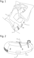
- a user person P is shown while lying in bed.
- the person P spoons a haptic respiration simulator 1 and touches the haptic respiration simulator 1 with a body part BP, here a hand.
- the haptic respiration simulator 1 is able to simulate a respiration by alternatingly contracting and expanding as will be explained in the below.
- the person P is able to sense said simulated respiration with hand BP. Research shows that when the simulated respiration is relatively slow compared to an average respiration of a person P, this has a relaxing effect on the user P.
- the haptic respiration device 1 may be used to relax a person P, e.g. during a busy day and while sitting in a comfortable chair (not shown), by holding the haptic respiration device 1, and sensing the comforting simulated respiration.
- the haptic respiration device may be used to guide a person towards a sleep phase by relaxing the user. More specifically, by inducing changes in the respiration frequency of the person P, the person P may be guided towards a state of (initial) sleep.
- the haptic respiration device 1 may be formed as a peanut-shaped pillow, having a soft outer skin 17, e.g. comprising a layer of foam material.
- the soft outer skin 17 may function as a third suspension to dampen noise originating from operation of a pump unit, which pump unit is positioned inside the haptic respiration simulator 1.
- This third suspension layer helps to silence the haptic respiration simulator 1 and makes it easier for person P to fall asleep and/or to relax, besides making the haptic respiration simulator more appealing to use for a user P.
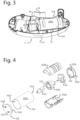
- the haptic respiration simulator 1 is here shown without user, and without the outer soft skin. Shown here is the outer housing 11 for housing components of the haptic respiration simulator, as well as inflatable air chamber 12. As is visible, the inflatable air chamber 12 is positioned outside or external of the outer housing 11. The inflatable air chamber 12 is in fluid communication with a pump unit arranged inside the outer housing and not visible in Figure 2 . The inflatable air chamber 12 is configured to simulate a respiration by repeated inflation (expansion) and deflation (contraction) of the inflatable air chamber 12. This inflation and deflation of the inflatable air chamber 12 can be sensed by a user through the outer skin of the haptic respiration simulator 1.
- the housing 11 may be made of a plastic material, that is preferably formed by an injection moulding process.
- Air is pumped in the inflatable air chamber 12 by a pump unit.
- the inflatable air chamber 12 is of a semi-permeable material, e.g. a material having small holes in it, so that the air chamber 12 automatically deflates, without the need for an air suction unit to deflate the inflatable air chamber 12. This decreases the amount of components needed.
- an air suction unit may be part of the haptic respiration simulator, e.g. to provide a better control over the respiration simulation.
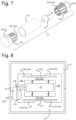
- the housing 11 houses several components of haptic respiration simulator 1, amongst which a pump unit, not visible, and the pump unit suspension system 15, of which tubular casing or tubular core 151 is well visible in Figure 3 .
- the pump unit suspension system 15, the pump unit, and the tubular casing 151 are positioned inside the housing 11.
- the pump unit is contained inside tubular casing 151 and therefore hidden from sight in Figure 3 .
- outer suspension 154 here in the form of foam material, positioned at the outside of a closed circumferential wall 1511 of the tubular casing, along different locations thereof.
- the foam material here in the form of blocks, suspend the tubular casing 151 with respect to the housing 11 and is placed between the tubular casing 151 and the housing 11, inside housing 11.
- the outer suspension 154 may also comprise a layer of suspension material, fully or partly surrounding the tubular casing 151.
- the layer of suspension material may comprise foam.
- FIG. 3 Also visible in Figure 3 is a (second) accumulator 16, positioned inside the housing 11 and outside of the tubular casing 151.
- the second accumulator 16 will be described in more detail below, with reference to Figure 6 .
- FIG. 4 an exploded view of components of the pump unit suspension system is shown.
- the tubular casing 151 is again shown, as well as components of the haptic respiration simulator associated with the tubular casing 151.
- a pair of end caps 153 is positioned at ends 1512, 1513 of the tubular casing 151, to seal the tubular casing 151.
- a pump unit 13 is positioned inside the tubular casing 151, and thus inside the housing 11. Pump unit 13 is in fluid communication with accumulator 14 and suspended with respect to the tubular casing 151 via inner suspension 152A, 152B, 152C. Also accumulator 14 and inner suspension 152A, 152B, 152C are positioned inside tubular casing 151 when the haptic respiration simulator is assembled.
- the tubular casing 151 has an inner volume 1514, in which the pump unit 13 is received.
- a circumferential wall 1511 of the tubular casing 151 is substantially closed, so as to prevent at least a part of the sound waves that result from an operation of the pump unit 13 to transfer outside of the tubular casing 151.
- the tubular casing 151 is round.
- the tubular casing 151 may however also be cylindrical, rectangular, triangular, or square, possibly with rounded edges.
- the tubular casing 151 may in principle have any shape.
- the tubular casing 151 is here hollow, and has open ends 1512, 1513.
- the circumferential wall 1511 is closed, i.e. has a continuous circumference without any holes, apertures or cutouts to optimally prevent the escape of sound waves in a radial direction.
- the circumferential wall 1511 may be made of steel, or other dense materials, e.g. metals with a density higher than steel.
- the circumferential wall 1511 is here thick-walled, having a thickness of at least 1 mm, e.g. 1.5mm, here at least 2.0mm.
- the pump unit 13 housed inside the tubular casing 151 when the haptic respiration simulator is assembled, is in fluid communication with the inflatable air chamber, for pumping air into the inflatable air chamber.
- the pump unit 13 is an axially operated pump unit, that provides pulses of air via an outlet 131 of the pump unit 13.
- the pump unit 13 is in fluid communication with the inflatable air chamber, components of the haptic respiration simulator may be placed in between the inflatable air chamber and the pump unit 13 (when seen in a flow direction from the pump unit 13 to the inflatable air chamber).
- the accumulator 14 is an example of such a component that may be placed in between the inflatable air chamber and the pump unit 13.
- the accumulator 14 is in fluid connection with the outlet 131 of the pump unit 13, and with the inlet of the inflatable air chamber (either directly, when there is only a single, first, accumulator, or indirectly, when there is a second accumulator. This will be explained in the below).
- the accumulator 14 is here positioned inside the tubular casing 151, when the haptic respiration simulator is assembled.
- the end caps 153 are here made of a resilient material, e.g. silicon. However, the end caps 153 may also be made of a relatively rigid material, e.g. a moulded plastic, or a metal such as steel. The end caps 153 or one of the end caps 153 may be integrated with the circumferential wall 1511 of the tubular casing 151 when the tubular casing 151 and the end caps 153 are made of the same material.
- end caps 153 are made of a relatively rigid material, but of a different material than the tubular casing 151, preferably resilient material is positioned between the end caps 153 and the tubular casing 151, such that a transfer of noise-inducing vibrations from the tubular casing 151 to the rigid end cap 153 is prevented.
- a passage hole 1535 Visible in one of the end caps 153 is therefore a passage hole 1535, e.g. for passage of an air tube that fluidly connects the accumulator 14 with the inflatable air chamber.
- the end caps 153 are substantially solid and completely seal the tubular casing 151, i.e. preferably the end caps do not comprise any holes through which noise may escape.
- the pump unit 13 should also be able to suck in fresh air for pumping it into the inflatable air chamber. Visible in the other of the end caps 153, are therefore suction holes 1536, 1537, through which the pump unit 13 may receive air, e.g. via air suction tubes. When an air tube is placed in the suction hole 1536, 1537, the amount of noise that can transfer outside of the tubular casing 151 may be significantly reduced compared to when the suction hole is left open.
- the inner suspension 152 for suspending the pump unit 13 with respect to the tubular casing 151 comprises here suspension member 152C and suspension shell 152A, 152B.
- the suspension member 152C and especially suspension shell 152A, 152B are preferably made of a material that is more resilient that the tubular casing 151.
- the suspension shell 152A, 152B may be made of a plastic material that is injection moulded.
- suspension member 152C may reduce the amount of air vibrations that result from operating the pump unit 13, by suspending pump unit 13 about a central position inside tubular casing 151, suspension shell 152A, 152B may prevent that air vibrations which do result from operation of the pump unit 13 are not, or only partially, transferred outside of tubular casing 151.
- the suspension member 152C of inner suspension 152 is shown in some more detail in Figures 5A and 5B .
- the suspension member 152C here comprises an inner circumferential wall 1525, an outer circumferential wall 1524, and at least three resilient elements 1521, 1522, 1523.
- the inner circumferential wall 1525 is for receiving the pump unit therein, and is connected to the outer circumferential wall 1524 via resilient elements 1521, 1522, 1523.
- the number of resilient elements 1521, 1522, 1523 here equals three, but of course more or less resilient elements may alternatively be chosen. However, to optimally stabilize and suspend the pump unit, at least three resilient elements are recommended.
- the resilient elements 1521, 1522, 1523 are arranged at different positions along the circumference of the pump unit, when the pump unit is placed inside the inner circumferential wall 1525 of the suspension member 152C, and suspend the pump unit about a central position in the internal volume of the tubular casing.
- Outer circumferential wall 1524 of suspension member 152C is arranged inside and against suspension shell 152A, 152B. Also accumulator 14 is arranged inside suspension shell 152A, 152C.
- an outside of the pump unit 13 may be positioned inside the suspension shell 152A, 152B, and inside suspension member 152C, against an inside of the inner circumferential wall 1525 of suspension member 152C.
- the end caps 153 are positioned at open ends 1512, 1513 of the tubular casing 151, with inwardly protruding wa1536lls 1531 of the end caps 153 being positioned against an inside of the closed circumferential wall 1511 of the tubular casing.
- these inwardly protruding walls 1531 slightly exceed the inner diameter of the tubular casing 151, to tightly fit the end cap 153 in the tubular casing 151.
- the outside of the suspension shell 152A, 152B may then positioned against the inside of the inwardly protruding walls 1531 of the end caps 153, inside tubular casing 151, between the pump unit 13 and the tubular casing 151.
- Outer circumferential wall 1524 of suspension member 152C and/or accumulator 14 may alternatively be placed against circumferential wall 1511 of the tubular casing 151 or against the inwardly protruding wall 1531 of end caps 153 when assembled, e.g. when suspension shell 152A, 152B is absent.
- FIG. 6 more schematically shows the pump unit suspension system 15 in an assembled state. All components of the pump unit suspension system 15 are here positioned inside housing 11, the only component of the haptic respiration simulator arranged outside of the housing 11 being the air chamber 12. However, as explained in the above, other components of the haptic respiration simulator, such as a foam cover, may also be positioned outside the housing 11. Positioned inside the housing 11 is a pump unit 13. When operated, the pump unit 13 produces noise. As the object of the haptic respiration simulator is to relax a user, this noise is disadvantageous, and the pump suspension unit 15 is provided to reduce the noise that originates from operating the pump unit 13, such that only a part of the noise is hearable by a user.
- the pump unit 13 may generate a noise level of more than 50dBA when operated, the pump unit suspension system being aimed at reducing that noise level with at least 10dBA, e.g. at least 13dBA, preferably with up to 20dBA or more to an overall noise level of 40dBA or below.
- the pump unit suspension system 15 comprises a first accumulator 14 and, optionally, a second accumulator 16.
- both accumulators 14, 16 are positioned inside the housing, with the first accumulator 14 being positioned inside an internal volume 1514 of the tubular casing 151, and the second accumulator 16 being positioned outside of the internal volume 1514 of the tubular casing 151.
- the pump unit 13 may provide a pulse-wise output of air, wherein these pulses of air may produce noise.
- the one or more accumulators 14, 16 are provided. They each store a volume of air in an internal volume thereof, and therefore smoothen the airflow through air tubes 131, 141, 161 from a pulse-wise character when the air leaves the air pump 13 to a more constant air stream when it enters the inflatable air chamber 12.
- the first accumulator 14 When seen in flow direction, the first accumulator 14 is positioned in between the pump unit 13 and the second accumulator 16, while being in fluid communication with the air chamber 12.
- the second accumulator 16 When seen in flow direction, the second accumulator 16 is positioned in between the first accumulator 14 and the air chamber 12, while being in fluid communication with the air pump 13.
- air tubes 139, 149, 169 between the pump unit 13, the accumulators 14, 16 and the air chamber 12 may be made of a resilient material, to dampen, reduce or prevent the amount of noise produced inside these tubes 139, 149, 169.
- the haptic respiration simulator may alternatively comprise one accumulator 14, no accumulator, or more than two accumulators.
- each of the accumulators 14, 16, if present, is positioned inside housing 11.
- One or more of them may additionally be positioned inside tubular casing 151, as here shown, but this is not necessary.
- the accumulator or accumulators may also be positioned outside of the tubular casing 151.
- an outer suspension 154 Positioned between the housing 11 and the tubular casing 151 is an outer suspension 154.
- This outer suspension 154 is here also positioned between end caps 153 and housing 11.
- the outer suspension 154 is here very schematically represented, and may be any type of suspension that prevents a contact between the housing 11 and tubular casing 151.
- tubular casing 151 sealed by end caps 153.
- the end caps 153 each have a double-walled circumferential wall, comprising an outer wall 1532 positioned at the outside of the tubular casing 151 and an inner wall 1531 positioned at the inside of the tubular casing 151.
- the end caps 153 may be made of a resilient material, or may be suspended with respect to the tubular casing 151. Preferably, no sound waves can be transferred from the tubular casing 151 to the end caps 153.
- the inner suspension 152A, 152B, 152C suspends the pump unit 13 with respect to the tubular casing 151, and here comprises suspension shell 152A, 152B and suspension member 152C.
- the suspension member 152C comprises resilient elements 1521, 1522.
- Inner circumferential wall 1531 of end caps 153 may prevent a physical contact between the suspension shell 152A, 152B and the tubular casing 151, to prevent sound waves to be transferred from the suspension shell 152A, 152B to the tubular casing 151.
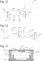
- FIG. 7 An alternative embodiment of pump suspension system 25 is shown with reference to figures 7-9 .
- Shown in figure 7 are a pump unit 13, inner suspension 252, tubular casing 151, and end caps 253.
- the end caps 253 have a double-walled circumferential wall with inner wall 2531 and outer wall 2532 that protrude towards the pump unit 13 when the pump unit suspension system 25 is assembled.
- the inner wall 2531 of the end cap 253 here functions as inner suspension 252. That is, the inner suspension 252 is integrated with the end cap 253.
- Each of the inner walls 2531 has a length equal to approximately half the length of the tubular casing 151, such that the inner walls 2531 touch each other when the end caps 253 are placed on the tubular casing 151.
- the end caps 253, and also the inner suspension 252 are made of a resilient material, e.g. silicon, and surround the pump unit 13, in both circumferential and axial direction.
- figure 7 shows an exploded view of the pump unit 13, end caps 253 and tubular casing 151
- figure 9 shows these components in an assembled state. From figure 9 , it follows that the inner wall 2531 of the double-walled circumferential wall may be arranged against an inner side of the tubular casing 151, while an outer wall 2532 of the double-walled circumferential wall may be arranged against an outer side of the tubular casing 151. As further visible from figure 8 , the outer wall 2532 of the end cap 253 may function as outer suspension 254 of pump unit suspension system 25, suspending the tubular casing 151 with respect to the housing 11.
- FIG. 8 Another schematic representation of this second embodiment is provided in Figure 8 . It is shown here how the end caps 253 comprise a double-walled circumferential wall, wherein an inner wall 2531 of the double-walled wall forms the inner suspension 252 of the pump unit suspension system 25, while an outer wall 2532 of the double-walled wall forms the outer suspension 254 of the pump unit suspension system 25.
- tubular casing 151 arranged around pump unit 13 and inside housing 11, an air tube 139 between pump unit 13 and accumulator 14, and an air suction tube 138 for providing fresh air to pump unit 13 even when it is fully surrounded by components of the pump unit suspension system.
- one or more breathing holes may additionally be provided in the end caps 153.
- Fig. 10 shows in a cross-sectional view a third embodiment of a pump unit suspension system 35 according to the invention.
- the pump unit suspension system 35 of this third embodiment comprises a double arrangement of the pump unit suspension system in the first and second embodiment.
- the pump unit suspension system 35 comprises a first and second tubular casing 351.1, 351.2, a first and second inner suspension 352.1, 352.2, a first and second pair of end caps 353.1, 353.2.
- the double arrangement of the pump unit suspension system is beneficial in obtaining a lightweight suspension which complies to a required noise reduction.
- the double arrangement is beneficial in that the second arrangement introduces a next acoustic decoupling.
- a total weight of the first and second tubular casing may be less than a weight of only the first tubular casing 151 due to a reduction of wall thickness.
- FIGS 11-15 show successive steps of assembling a pump unit 13 into the pump unit suspension 35.
- Fig. 11 shows the first inner suspension 352.1.
- the first inner suspension 352.1 is made of a resilient material e.g. silicon.
- the first inner suspension 352.1 and a first pair of end caps 353.1 are incorporated to form a one-piece item.
- the first inner suspension 352.1 and the first pair of end caps 353.1 are integral.
- the first inner suspension 352.1 and the first pair of end caps 353.1 are made of a single material.
- it is conceivable to integrate the first inner suspension and the first pair of end caps being made of different materials.
- a first pair end caps 353.1 with integrated first inner suspension may be made using a 2K injection moulding process, wherein two different materials may be used to produce the item.
- the first inner suspension 352.1 is cylindrically shaped.
- the first inner suspension 352.1 has an hollow inner space defined by a circumferential wall for receiving the pump unit 13.
- the hollow inner space is laterally open for receiving the pump unit 13 from aside as indicated by the arrows.
- the circumferential wall has an inner circumferential wall for receiving the pump unit therein.
- the pump unit 13 is insertable through an open region of the circumferential wall to be installed in the inner space.
- the resilient material of the first inner suspension 352.1 which is preferably silicone material, allows the circumferential wall to be wrapped around the pump unit 13.
- the first inner suspension 352.1 has a circumferential wall which is open at a middle region and open at an opposite lateral side at the at least one end region. The pump unit 13 is inserted into the hollow inner space through the opening at an end region.
- the circumferential wall includes at least one bridge portion in between neighbouring openings. Each bridge portion forms a resilient element 3521, 3522 for suspending the pump unit 13.
- the first inner suspension 352.1 includes four resilient members. A pair of resilient members 3521, 3522 is positioned at a proximal end of the pump unit 13 and a pair of resilient members 3523, 3524 is positioned at a distal end of the pump unit 13.
- Fig. 12 and 13 show a next step of the assembly of the pump unit 13 in the pump unit suspension system 35.
- the first tubular casing 351.1 has a hollow casing body with a substantially closed circumferential wall 3511 and has a first and second open end 3512, 3513.
- the first tubular casing 351.1 is made of metal, in particular steel.
- the subassembly including the pump unit 13 is moved through the first tubular casing 351.1 to obtain the subassembly as shown in fig. 13 .
- the first pair of end caps 353.1 is in abutting engagement with the ends of the casing body to close the open ends 3512, 3513.
- At least one of the end caps is provided with at least one through passageway 3536 for passing an air conduit or electrical wire.
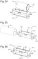
- Fig. 14 and 15 show a next step of an assembly of the pump unit suspension system 35, in which the subassembly of the first tubular casing 351.1 including the first inner suspension with integral pair of end caps 352.1, 353.1 and the pump unit 13 is received in a second inner suspension 352.2.
- the second inner suspension 352.2 is separately shown in fig. 16 .
- the second inner suspension 352.2 is made of a resilient material, preferably silicone material.
- the second inner suspension 352.2 is integrally formed with a second pair of end caps 353.2.
- the second inner suspension 352.2 has an outer circumferential wall which is formed by three longitudinally extending wall portions. An inner space is provided in between the extending wall portions for receiving the subassembly as shown in fig. 13 .
- Each extending wall portion forms a resilient element 3521.2 for holding the subassembly.
- the subassembly of the first tubular casing 351.1 as shown in Fig. 13 is received in between the extending wall portions. Subsequently, the subassembly of the second inner suspension 352.2 and the first tubular casing 351.1 is moved into the second tubular casing 351.2 to obtain the assembly as shown in fig. 10 .
- Each extending wall portion has a stopper 3529.
- the stopper is pad-shaped and integrally formed with the wall portion. Here the stopper is positioned at a middle region.
- the stopper subdivides the wall portion into two resilient elements. In the assembly as shown in fig. 10 , the stopper 3529 is in abutting engagement with the second tubular casing 351.2 2 to carry a weight of the subassembly. Only locally, by the stopper 3529, the extending wall portion contacts the second tubular casing 351.2 which is beneficial in limiting a transfer of vibrations to the outside.
- the subassembly can be clamped inside the second tubular casing 351.2. Due to the double arrangement including an additional acoustic decoupling, at least one of the first and second tubular casing 351.1, 351.2 may be configured with a reduced wall thickness, or another material selection, like plastic instead of steel.
- Fig. 17 is an enlarged view of an end of the second tubular casing 351.2 showing an outer suspension 354 for mounting the subassembly of both the first and second tubular casing 351.1, 351.2 to a housing 11 as it is illustrated in fig. 18 .
- Each end cap of the second pair of end caps 353.2 has a mounting flange forming the outer suspension 354.
- the mounting flange extends perpendicular to an end cap body.
- the mounting flange may be screwed or clamped to the housing 11.
- the mounting flange includes at least one bore hole for screwing the subassembly to the housing 11.
- the mounting flange provides flexibility to the outer suspension 354.
- the configuration of the mounting flange is beneficial in providing an predetermined damping, because a thickness and length of the mounting flange can be designed in a dedicated manner to adapt to a particular design of the pump unit.
Landscapes
- Health & Medical Sciences (AREA)
- Anesthesiology (AREA)
- Pain & Pain Management (AREA)
- Physics & Mathematics (AREA)
- Acoustics & Sound (AREA)
- Psychology (AREA)
- Engineering & Computer Science (AREA)
- Biomedical Technology (AREA)
- Heart & Thoracic Surgery (AREA)
- Hematology (AREA)
- Life Sciences & Earth Sciences (AREA)
- Animal Behavior & Ethology (AREA)
- General Health & Medical Sciences (AREA)
- Public Health (AREA)
- Veterinary Medicine (AREA)
- Measurement Of The Respiration, Hearing Ability, Form, And Blood Characteristics Of Living Organisms (AREA)
- Percussion Or Vibration Massage (AREA)
Description
- The present invention relates in first aspect to a haptic respiration simulator, e.g. in the form of a pillow or a teddy, comprising a noise reducing pump suspension.
-
US2011/0301405 discloses a sleeping inducer in the form of a pillow or a doll, comprising a movable plate arranged inside a cover. The moving plate can repeatedly and vertically be moved by moving means. This way, the sleeping inducer can move like a lung that shrinks and expands. In another embodiment a pad filled with air is contained in the cover, between the moving plate and the cover. By moving the moving plate, the pad shrinks and expands. A user of the sleeping inducer, upon going to bed, hugs, grips or touches the sleeping inducer and has an experience resembling being hugged and slept by a mom. - It is a disadvantage of such sleeping inducers that they produce noise or sounds by operating the moving means. This noise may be experienced as annoying by users, especially when they use the sleeping inducer to try and fall asleep more easily in an otherwise quiet bedroom. Further prior art devices are disclosed by the following documents:
US4 606 328A ,US2011/301405A1 ,US8 220 089B1 andWO2014/061789A1 . - The general object of the first aspect of the present invention is to at least partially eliminate the above mentioned drawback and/or to provide a usable alternative. More specifically, it is an object of the invention to provide a haptic respiration simulator that is silent, e.g. that produces sounds not exceeding average bedroom-level sounds
- This object is achieved by a haptic respiration simulator according to
claim 1. - When the haptic respiration simulator is used, i.e. when the pump unit is operated, sound or noise is inherently produced. The applicant has found that this noise mainly stems from four different sources. Firstly, providing small air pulses by operating the pump unit results in a vibration of air inside an air tube that connects the pump unit with the air chamber or other components. These vibrations result in sound waves which can be heard by a user. Secondly, the pump unit may physically move when it is operated. This movement of the pump unit results in a vibration of the air that surrounds the pump unit. This vibrating air results in sound waves which can be heard by a user. Thirdly, when the pump unit is operated, it may touch other (hard) components of the haptic respiration simulator. Also this touching or hitting of (hard) components produces sounds. Fourthly, the resonating vibration of certain components of the haptic respiration simulator, activated by vibrating air, may also result in sound, just like the vibration of a speaker diaphragm.
- To optimally silence the haptic respiration simulator, each of these sources of noise should be prevented, reduced or dampened, such that a user of the simulator does not hear this noise while using the haptic respiration simulator. Ideally, a user cannot hear the simulator when he or she is in a silent environment, such as a bedroom, and uses the haptic respiration simulator. Preferably, the resulting noise produced by the simulator is reduced to below 40 dBA, more preferably to below 37dBA, e.g. to about 32dBA or less when measured at a position outside of the haptic respiration simulator, at a distance of 25 cm. This distance approximates the distance between ears of the user and the haptic respiration simulator in a normal or conventional operational mode of the haptic respiration simulator.
- As a first noise-reducing measure, the haptic respiration simulator may comprise at least one accumulator for accumulating air and for reducing noise originating from a pumping action of the pump unit, i.e. for reducing the first source of sound described in the above. When seen in flow direction, the accumulator is arranged between the pump unit and the inflatable air chamber. In other words: the accumulator is in fluid communication with an outlet of the pump unit and an inlet of the inflatable air chamber.
- The accumulator accumulates or buffers air in an internal volume thereof. The accumulator receives, in operation, pulses of air from the pump unit and supplies a stream of air to the inflatable air chamber. The accumulator thus smoothens the pulse-wise supply of air by the pump unit into a more constant stream of air supplied to the inflatable air chamber. This reduces the amount of noise generated by the haptic respiration simulator.
- The haptic respiration simulator may further comprise a pump unit suspension system for reducing noise originating from operation of the pump unit, i.e. the second, third and fourth source of sound described in the above. The pump unit suspension system may damp sound waves resulting from physical movement of the pump unit when operated and damps or prevent sounds induced by (hard) components that touch or hit each other during operation of the pump unit. The suspension system may furthermore stabilize each component thereof to prevent it from vibrating like a speaker diaphragm.
- The pump unit suspension system may comprise a tubular casing, an inner suspension, a pair of end caps, and an outer suspension. The inner suspension and the end caps are at least partly arranged inside the tubular casing, such that the tubular casing, the inner suspension and the end caps together encapsulate the pump unit and prevent sound waves from transferring outside of the tubular casing.
- The tubular casing, which preferably has a substantially closed circumferential wall but which may have open ends to allow tubes and wires associated with the pump to protrude from the tubular casing, is more preferably thick-walled and made of a dense and heavy material such as steel (see below for more details). The inner suspension is preferably made of a less dense and less heavy material than the tubular casing (see below for more details). The use of such a double-layered sound isolation comprising a tubular casing and an inner suspension ensures that sound waves resulting from operating the pump unit must transfer trough two separate barriers before they can radially escape out of the tubular casing, out of the haptic respiration simulator, and produce sound that can be heard by a user. This double-layered sound isolation of the pump unit suspension system is more efficient than a relatively thicker layer of a single material, as the first barrier and the second barrier may advantageously each prevent the transmission of different frequencies of sound waves, while also having different critical frequencies themselves.
- Preferably, the tubular casing furthermore is made of a heavy, dense material such as steel, such that the pump unit suspension system is stabilized by the mere weight of the tubular casing and vibrations of components are prevented. This further prevents or reduces sound emitted by the haptic respiration simulator.
- The inner suspension, besides acting as a barrier for sound waves as described in the above, additionally suspends the pump unit with respect to the tubular casing and e.g. ensures that the pump unit remains at a central position in the tubular casing. The inner suspension thereby e.g. prevents the pump unit to physically touch the tubular casing when it is operated.
- The end caps, arranged at each end of the tubular casing, may prevent an axial transfer of sound waves outside of the tubular casing by sealing the tubular casing. A first end cap and a second end cap of the pair of end caps may be similar, e.g. having a same diameter, and being made of the same material. The two end caps of the pair of end caps may however also be different from each other, e.g. when the one end of the tubular casing is differently shaped with respect to the other end of the tubular casing, or e.g. made of different materials. Each of the end caps seals one end of the tubular casing, and is arranged at that end.
- The outer suspension is provided at the outside of the tubular casing, e.g. against the circumferential wall of the tubular casing and suspends the tubular casing with respect to the housing. The outer suspension is thus arranged between the tubular casing and the housing, and prevents the transfer of sound waves or vibrations from the tubular casing to the housing. Additionally, the outer suspension may provide a third barrier between sound waves originating from operation of the pump and transferred outside of the tubular casing towards ears of the user.
- These combined features of an accumulator and a pump unit suspension system, as described, together help to prevent, reduce or damp the noise produced by the haptic respiration simulator when the pump unit is working, to a noise level hearable by a user that is preferably at or below bedroom-level sound, e.g. below 40 dBA, preferably below 37 dBA.
- In embodiments, e.g. when the pump unit may be silently operated in view of pulses of air and/or when the pump unit is able to provide a constant (silent) air stream, the accumulator may be optional. The pump unit may be fluidly connected to the inflatable air chamber without an accumulator. The accumulator provided as a separate item to be fluidly connected in between the pump unit and the inflatable air chamber is optional. An accumulator may also be provided by an substantially airtight volume situated inside the assembly of the pump unit suspension system in between an outlet of the pump unit and an inlet conduit upstream the inflatable air chamber. The accumulator may be formed by a volume surrounding the pump unit in the assembly. In particular, the accumulator may be formed by a closed chamber of the inner suspension in which the chamber has a port for connecting the outlet of the pump unit and a port for pressurising the inflatable air chamber. An accumulator may be formed by an airtight compartment integral with an end cap in which the compartment is situated in between the outlet of the pump unit and an inner side of an end cap in which the compartment is provided with an outlet in fluid connection with the inflatable air chamber.
- In embodiments, e.g. when the tubular casing comprises one or two end walls, e.g. of the same material as the circumferential wall thereof, one or both of the pair of end caps may be optional.
- In embodiments, e.g. when the housing is at least partially made of a soft or resilient material, e.g. at the location of the tubular casing, the outer suspension may be optional.
- In embodiments the inner suspension and the end caps may be integrated into a single component, as will be described in more detail below.
- In embodiments, e.g. when a suspension suspends the pump unit with respect to the housing, the tubular casing may be optional.
- In embodiments, e.g. when all components of the haptic respiration device which are arranged inside the housing are also arranged inside the tubular casing, the tubular casing may define the housing of the haptic respiration device.
- The haptic respiration simulator, which is suited for relaxing a user by simulating a respiration that can be sensed by a body part, e.g. a hand, of the user, may e.g. be a sleep induction device, a stress relief device or a relaxation device. The haptic respiration simulator may e.g. be grabbed, hugged, touched, or contacted in another way by a user thereof. For example, the haptic respiration simulator may be formed as a pillow or a doll, e.g. having a peanut shape of a sleep induction device as disclosed in
WO2018186739 . In use, the user feels a movement of the haptic respiration simulator, which movement resembles a respiration of a person. More particularly, continuous inflation and deflation of the inflatable air chamber results in a movement of the haptic respiration simulator which is recognized by the user as a simulation of a respiratory action of a human. Preferably the simulated respiration has a relatively low frequency, around the frequency that an average person has when he or she is asleep. By using the haptic respiration simulator, and experiencing the low frequency respiration simulation, a user relaxes and may e.g. fall asleep or relieve stress during a busy day. - The haptic respiration simulator comprises a housing for housing components. The housing may at least partially be made of a rigid plastic material, e.g. formed by an injection moulding process. In embodiments, the housing and/or the haptic respiration simulator has a peanut-shape. In embodiments, the housing is covered with a layer of foam material, the haptic respiration simulator e.g. having a soft touch. The housing may have in internal volume in which components of the haptic respiration simulator, e.g. the pump unit, the accumulator or accumulators, the pump unit suspension system, and electronics may be placed.
- The haptic respiration simulator comprises an inflatable air chamber, e.g. outside of the housing or integrated with an external wall of the housing, which is configured to simulate a respiration, e.g. of a user or a person, by repeated inflation and deflation. The inflation and deflation of the inflatable air chamber may be noticed by a user of the haptic respiration simulator when holding the simulator in hands of the user; the deflation and inflation of the air chamber resembling a respiration of a person.
- The haptic respiration simulator comprises a pump unit that is positioned inside the housing. The pump unit supplies air to the accumulator and is, indirectly, in fluid communication with the inflatable air chamber, such that it can pump a volume or air into the inflatable air chamber.
- In an embodiment, the tubular casing is hollow and has open ends, is made of steel and is thick-walled, i.e. has a thickness of at least 1 mm, e.g. 1.5mm or 2mm. The tubular casing may be hollow to allow it to receive other components of the haptic respiration simulator therein, for example the inner suspension, the pump unit and/or the accumulator. The tubular casing may be made of thick-walled steel to prevent sound waves to escape from the tubular casing in a radial direction. When the tubular casing is heavier (i.e. made of a more dense material and/or thicker), it is more difficult for sound waves to transfer through the tubular casing. Additionally, the weight of thick-walled steel also stabilizes the tubular casing, to reduce and/or prevent resonating vibrations of any components of the haptic respiration simulator.
- Alternatively, the tubular casing may also be made of other materials or have another thickness. For example, the tubular casing may be made of a material having a density that is about 1/3 of the density of steel, while being three times as thick, e.g. at least 3 mm. An example of such a material is aluminium. Of course, other materials may be chosen according to the same principle. E.g. a material that is 10% denser than steel, and 10% thinner.
- In an embodiment, the inner suspension comprises at least three resilient elements, arranged at different positions along the circumference of the pump unit, the at least three resilient elements suspending the pump unit about a central position in an internal volume of the tubular casing. The inner suspension may comprise at least three spring-like resilient elements, e.g. for suspending the pump unit at three or more discrete positions along the circumference of the pump unit.
- In an embodiment, the inner suspension comprises a resilient material, e.g. silicon, that surrounds the pump unit, at least in a circumferential direction thereof. The inner suspension may e.g. be wrapped around the pump unit, to physically separate it from the tubular casing. By wrapping the pump unit in a resilient material, the resilient material acts as a suspension for the pump unit with respect to the tubular casing. The resilient material may lie against the pump unit with one side thereof, while it may lie against an inner side of the tubular casing with another, opposing, side thereof.
- In an embodiment, the inner suspension and the end caps are made of the same material and are integrated with each other. For example, an inner circumferential wall of the end caps may be embodied as inner suspension. With this arrangement, the number of parts is reduced, which may result in a lower overall cost. Additionally, assembly of the pump unit suspension system may be quicker with less parts, which again may result in a lower overall cost.
- Furthermore, when the inner suspension and the end caps are integrated, the inner suspension may be relatively thin. As a result, the inner diameter of the tubular casing may be smaller, which saves weight. This makes the haptic respiration simulator lighter, which may be more comforting for users thereof.
- The inner suspension and the end caps may also be integrated while being made of different materials. For example, an end cap with integrated inner suspension may be made using a 2K injection moulding process, wherein two different materials may be used to produce the end cap.
- In an embodiment, the pump unit suspension system comprises a second tubular casing, a second inner suspension and a second pair of end caps for suspending a subassembly of a first tubular casing, a first inner suspension, and a first pair of end caps. Such a double arrangement is beneficial in that an additional acoustic decoupling is provided which further reduces a transfer of vibrations.
- In an embodiment, the end caps have a double-walled circumferential wall that protrudes towards the pump unit when the pump unit suspension system is assembled, an inner wall of the double-walled circumferential wall e.g. being arranged against an inner side of the tubular casing, an outer wall of the double-walled circumferential wall e.g. being arranged against an outer side of the tubular casing. The inner wall may then form the inner suspension and/or the outer wall may then form the outer suspension. This specific embodiment may result in less parts and faster assembly, saving costs.
- In an embodiment, the outer suspension comprises foam material, e.g. at least six blocks of foam material, provided at different locations along the circumferential wall of the tubular casing, between said wall and the housing. It is not required that the outer suspension fully surrounds the tubular casing, although this is possible. The outer suspension may comprise a number of different suspensive elements, that are positioned at several discrete locations along the circumferential wall of the tubular casing.
- In an embodiment, the haptic respiration simulator further comprises a second accumulator for accumulating air and for (further) reducing noise originating from a pumping action of the pump unit, the second accumulator being in direct fluid communication with an outlet of the first accumulator and an inlet of the inflatable air chamber, and in indirect fluid communication with the pump unit. In streamwise direction, starting at the outlet of the pump unit, air may go from the pump unit to the first accumulator, then to the second accumulator, before entering the air chamber. The haptic respiration simulator may comprise more than two accumulators.
- The first and second accumulator may be integrated in a single component, e.g. separated by a partition.
- In an embodiment, at least one of the accumulators or the accumulator may be positioned inside the housing, outside of an internal volume of the tubular casing. That is, the only accumulator may be positioned outside an internal volume of the tubular casing, both or all accumulators may be positioned outside an internal volume of the tubular casing, or a subset of all accumulators may be positioned outside an internal volume of the tubular casing, while other accumulators, if present, may be positioned inside the tubular casing. When one or more of the accumulators are positioned outside the tubular casing, the internal volume of the tubular casing required to house all components may be smaller. As a result, the diameter of the tubular casing may be smaller or its length may be shorter, resulting in a lighter part. As the weight of the tubular casing may make up a significant portion of the weight of the haptic respiration simulator, e.g. 5% - 25%, reducing the weight of the tubular casing may significantly reduce the weight of the haptic respiration simulator.
- In an embodiment, the inflatable air chamber is positioned external of the housing, to optimally transfer the respiration simulation to a body part of a user. The inflatable air chamber may also be arranged as part of the housing. Alternatively, the air chamber may be arranged inside the housing, e.g. against a part of the housing that is made of a flexible material, such that the inflation and deflation of the air chamber can be sensed by a user. Preferably, the inflatable air chamber is positioned at the outer side of the housing.
- The invention further relates to a method for relaxation of a user, wherein use is made of the haptic respiration simulator as described above.
- The invention further relates to a method for guiding a user towards a sleep state, wherein use is made of the haptic respiration simulator as described in the above.
- The invention will be explained in more detail with reference to the appended drawings. The drawings show practical embodiments according to the invention, which may not be interpreted as limiting the scope of the invention. Specific features may also be considered apart from the shown embodiments and may be taken into account in a broader context as a delimiting feature, not only for the shown embodiment but as a common feature for all embodiments falling within the scope of the appended claims. In the figures:
-
Figure 1 schematically shows a user lying in bed while spooning and holding an embodiment of a haptic respiration simulator according to the invention; -
Figure 2 schematically shows a housing of the haptic respiration simulator offigure 1 ; -
Figure 3 schematically shows the inside of the housing ofFigure 2 ; -
Figure 4 schematically shows a first embodiment of the pump unit and the pump unit suspension system according to the invention; -
Figures 5a and 5b schematically show a more detailed view of the inner suspension as shown inFigure 4 ; -
Figure 6 schematically shows the layout of the pump unit suspension system ofFigure 4 , arranged inside the housing; -
Figure 7 schematically shows a second embodiment of a pump unit and a pump unit suspension system according to the invention; -
Figure 8 schematically shows the layout of the pump unit suspension system ofFigure 7 , arranged inside the housing; -
Figure 9 schematically shows the embodiment ofFig. 7 in an assembled statea pump unit suspension system according to the invention; -
fig. 10-12 show a third embodiment of the pump unit suspension system according to the invention, wherein a pair of end caps is integrated with and inner suspension; and -
fig. 13-18 show an embodiment, wherein the pump unit suspension system comprises a double set of inner suspensions, pair of end caps and tubular casing; - With reference to
Figure 1 a user, person P, is shown while lying in bed. The person P spoons ahaptic respiration simulator 1 and touches thehaptic respiration simulator 1 with a body part BP, here a hand. Thehaptic respiration simulator 1 is able to simulate a respiration by alternatingly contracting and expanding as will be explained in the below. The person P is able to sense said simulated respiration with hand BP. Research shows that when the simulated respiration is relatively slow compared to an average respiration of a person P, this has a relaxing effect on the user P. - For example, the
haptic respiration device 1 may be used to relax a person P, e.g. during a busy day and while sitting in a comfortable chair (not shown), by holding thehaptic respiration device 1, and sensing the comforting simulated respiration. - For example, the haptic respiration device may be used to guide a person towards a sleep phase by relaxing the user. More specifically, by inducing changes in the respiration frequency of the person P, the person P may be guided towards a state of (initial) sleep.
- As is visible in
Figure 1 , thehaptic respiration device 1 may be formed as a peanut-shaped pillow, having a softouter skin 17, e.g. comprising a layer of foam material. As will become more clear from the below, the softouter skin 17 may function as a third suspension to dampen noise originating from operation of a pump unit, which pump unit is positioned inside thehaptic respiration simulator 1. This third suspension layer helps to silence thehaptic respiration simulator 1 and makes it easier for person P to fall asleep and/or to relax, besides making the haptic respiration simulator more appealing to use for a user P. - Turning to
Figure 2 , thehaptic respiration simulator 1 is here shown without user, and without the outer soft skin. Shown here is theouter housing 11 for housing components of the haptic respiration simulator, as well asinflatable air chamber 12. As is visible, theinflatable air chamber 12 is positioned outside or external of theouter housing 11. Theinflatable air chamber 12 is in fluid communication with a pump unit arranged inside the outer housing and not visible inFigure 2 . Theinflatable air chamber 12 is configured to simulate a respiration by repeated inflation (expansion) and deflation (contraction) of theinflatable air chamber 12. This inflation and deflation of theinflatable air chamber 12 can be sensed by a user through the outer skin of thehaptic respiration simulator 1. - The
housing 11 may be made of a plastic material, that is preferably formed by an injection moulding process. - Air is pumped in the
inflatable air chamber 12 by a pump unit. Preferably, theinflatable air chamber 12 is of a semi-permeable material, e.g. a material having small holes in it, so that theair chamber 12 automatically deflates, without the need for an air suction unit to deflate theinflatable air chamber 12. This decreases the amount of components needed. However, an air suction unit may be part of the haptic respiration simulator, e.g. to provide a better control over the respiration simulation. - Turning now to
Figure 3 , the inside of thehousing 11 is visible, as well as theinflatable air chamber 12 which is arranged outside of thehousing 11. Thehousing 11 houses several components ofhaptic respiration simulator 1, amongst which a pump unit, not visible, and the pumpunit suspension system 15, of which tubular casing ortubular core 151 is well visible inFigure 3 . Hence, the pumpunit suspension system 15, the pump unit, and thetubular casing 151 are positioned inside thehousing 11. The pump unit is contained insidetubular casing 151 and therefore hidden from sight inFigure 3 . Also visible inFigure 3 isouter suspension 154, here in the form of foam material, positioned at the outside of a closedcircumferential wall 1511 of the tubular casing, along different locations thereof. The foam material, here in the form of blocks, suspend thetubular casing 151 with respect to thehousing 11 and is placed between thetubular casing 151 and thehousing 11, insidehousing 11. - However, the
outer suspension 154 may also comprise a layer of suspension material, fully or partly surrounding thetubular casing 151. For example, the layer of suspension material may comprise foam. - Also visible in
Figure 3 is a (second)accumulator 16, positioned inside thehousing 11 and outside of thetubular casing 151. Thesecond accumulator 16 will be described in more detail below, with reference toFigure 6 . - Turning to
Figure 4 , an exploded view of components of the pump unit suspension system is shown. Thetubular casing 151 is again shown, as well as components of the haptic respiration simulator associated with thetubular casing 151. A pair ofend caps 153 is positioned at ends 1512, 1513 of thetubular casing 151, to seal thetubular casing 151. Apump unit 13 is positioned inside thetubular casing 151, and thus inside thehousing 11.Pump unit 13 is in fluid communication withaccumulator 14 and suspended with respect to thetubular casing 151 viainner suspension accumulator 14 andinner suspension tubular casing 151 when the haptic respiration simulator is assembled. - The
tubular casing 151 has aninner volume 1514, in which thepump unit 13 is received. Acircumferential wall 1511 of thetubular casing 151 is substantially closed, so as to prevent at least a part of the sound waves that result from an operation of thepump unit 13 to transfer outside of thetubular casing 151. - In the shown embodiment, the
tubular casing 151 is round. Thetubular casing 151 may however also be cylindrical, rectangular, triangular, or square, possibly with rounded edges. Thetubular casing 151 may in principle have any shape. - The
tubular casing 151 is here hollow, and hasopen ends circumferential wall 1511 is closed, i.e. has a continuous circumference without any holes, apertures or cutouts to optimally prevent the escape of sound waves in a radial direction. Thecircumferential wall 1511 may be made of steel, or other dense materials, e.g. metals with a density higher than steel. Thecircumferential wall 1511 is here thick-walled, having a thickness of at least 1 mm, e.g. 1.5mm, here at least 2.0mm. - The
pump unit 13, housed inside thetubular casing 151 when the haptic respiration simulator is assembled, is in fluid communication with the inflatable air chamber, for pumping air into the inflatable air chamber. Preferably, thepump unit 13 is an axially operated pump unit, that provides pulses of air via anoutlet 131 of thepump unit 13. Although thepump unit 13 is in fluid communication with the inflatable air chamber, components of the haptic respiration simulator may be placed in between the inflatable air chamber and the pump unit 13 (when seen in a flow direction from thepump unit 13 to the inflatable air chamber). - The
accumulator 14 is an example of such a component that may be placed in between the inflatable air chamber and thepump unit 13. Theaccumulator 14 is in fluid connection with theoutlet 131 of thepump unit 13, and with the inlet of the inflatable air chamber (either directly, when there is only a single, first, accumulator, or indirectly, when there is a second accumulator. This will be explained in the below). Theaccumulator 14 is here positioned inside thetubular casing 151, when the haptic respiration simulator is assembled. - The end caps 153 are here made of a resilient material, e.g. silicon. However, the end caps 153 may also be made of a relatively rigid material, e.g. a moulded plastic, or a metal such as steel. The end caps 153 or one of the end caps 153 may be integrated with the
circumferential wall 1511 of thetubular casing 151 when thetubular casing 151 and the end caps 153 are made of the same material. When the end caps 153 are made of a relatively rigid material, but of a different material than thetubular casing 151, preferably resilient material is positioned between the end caps 153 and thetubular casing 151, such that a transfer of noise-inducing vibrations from thetubular casing 151 to therigid end cap 153 is prevented. - Visible in one of the end caps 153 is therefore a
passage hole 1535, e.g. for passage of an air tube that fluidly connects theaccumulator 14 with the inflatable air chamber. - Preferably, as shown, the end caps 153 are substantially solid and completely seal the
tubular casing 151, i.e. preferably the end caps do not comprise any holes through which noise may escape. - However, the
pump unit 13 should also be able to suck in fresh air for pumping it into the inflatable air chamber. Visible in the other of the end caps 153, are therefore suction holes 1536, 1537, through which thepump unit 13 may receive air, e.g. via air suction tubes. When an air tube is placed in thesuction hole tubular casing 151 may be significantly reduced compared to when the suction hole is left open. - The inner suspension 152 for suspending the
pump unit 13 with respect to thetubular casing 151 comprises heresuspension member 152C and suspension shell 152A, 152B. Thesuspension member 152C and especiallysuspension shell tubular casing 151. For example, when thetubular casing 151 is made of a metal, thesuspension shell unit suspension system 15 is assembled,suspension shell pump unit 13,accumulator 14, andsuspension member 152C. - While
suspension member 152C may reduce the amount of air vibrations that result from operating thepump unit 13, by suspendingpump unit 13 about a central position insidetubular casing 151,suspension shell pump unit 13 are not, or only partially, transferred outside oftubular casing 151. - The
suspension member 152C of inner suspension 152 is shown in some more detail inFigures 5A and 5B . As shown, thesuspension member 152C here comprises an innercircumferential wall 1525, an outercircumferential wall 1524, and at least threeresilient elements circumferential wall 1525 is for receiving the pump unit therein, and is connected to the outercircumferential wall 1524 viaresilient elements resilient elements resilient elements circumferential wall 1525 of thesuspension member 152C, and suspend the pump unit about a central position in the internal volume of the tubular casing. - Outer
circumferential wall 1524 ofsuspension member 152C is arranged inside and againstsuspension shell accumulator 14 is arranged insidesuspension shell - Returning to
Figure 4 , when the haptic respiration simulator is assembled, an outside of thepump unit 13 may be positioned inside thesuspension shell suspension member 152C, against an inside of the innercircumferential wall 1525 ofsuspension member 152C. The end caps 153 are positioned atopen ends tubular casing 151, with inwardly protruding wa1536lls 1531 of the end caps 153 being positioned against an inside of the closedcircumferential wall 1511 of the tubular casing. Preferably, these inwardly protrudingwalls 1531 slightly exceed the inner diameter of thetubular casing 151, to tightly fit theend cap 153 in thetubular casing 151. The outside of thesuspension shell walls 1531 of the end caps 153, insidetubular casing 151, between thepump unit 13 and thetubular casing 151. - Outer
circumferential wall 1524 ofsuspension member 152C and/oraccumulator 14 may alternatively be placed againstcircumferential wall 1511 of thetubular casing 151 or against the inwardly protrudingwall 1531 ofend caps 153 when assembled, e.g. when suspension shell 152A, 152B is absent. -
Figure 6 more schematically shows the pumpunit suspension system 15 in an assembled state. All components of the pumpunit suspension system 15 are here positioned insidehousing 11, the only component of the haptic respiration simulator arranged outside of thehousing 11 being theair chamber 12. However, as explained in the above, other components of the haptic respiration simulator, such as a foam cover, may also be positioned outside thehousing 11. Positioned inside thehousing 11 is apump unit 13. When operated, thepump unit 13 produces noise. As the object of the haptic respiration simulator is to relax a user, this noise is disadvantageous, and thepump suspension unit 15 is provided to reduce the noise that originates from operating thepump unit 13, such that only a part of the noise is hearable by a user. For example, thepump unit 13 may generate a noise level of more than 50dBA when operated, the pump unit suspension system being aimed at reducing that noise level with at least 10dBA, e.g. at least 13dBA, preferably with up to 20dBA or more to an overall noise level of 40dBA or below. - Therefore, the pump
unit suspension system 15 comprises afirst accumulator 14 and, optionally, asecond accumulator 16. Here, bothaccumulators first accumulator 14 being positioned inside aninternal volume 1514 of thetubular casing 151, and thesecond accumulator 16 being positioned outside of theinternal volume 1514 of thetubular casing 151. Thepump unit 13 may provide a pulse-wise output of air, wherein these pulses of air may produce noise. To reduce this noise, the one ormore accumulators air tubes 131, 141, 161 from a pulse-wise character when the air leaves theair pump 13 to a more constant air stream when it enters theinflatable air chamber 12. - When seen in flow direction, the
first accumulator 14 is positioned in between thepump unit 13 and thesecond accumulator 16, while being in fluid communication with theair chamber 12. When seen in flow direction, thesecond accumulator 16 is positioned in between thefirst accumulator 14 and theair chamber 12, while being in fluid communication with theair pump 13. - As indicated,
air tubes pump unit 13, theaccumulators air chamber 12 may be made of a resilient material, to dampen, reduce or prevent the amount of noise produced inside thesetubes - Although here two
accumulators accumulator 14, no accumulator, or more than two accumulators. Preferably, each of theaccumulators housing 11. One or more of them may additionally be positioned insidetubular casing 151, as here shown, but this is not necessary. The accumulator or accumulators may also be positioned outside of thetubular casing 151. - Positioned between the
housing 11 and thetubular casing 151 is anouter suspension 154. Thisouter suspension 154 is here also positioned betweenend caps 153 andhousing 11. Theouter suspension 154 is here very schematically represented, and may be any type of suspension that prevents a contact between thehousing 11 andtubular casing 151. - Further visible in
Figure 6 istubular casing 151, sealed byend caps 153. The end caps 153 each have a double-walled circumferential wall, comprising anouter wall 1532 positioned at the outside of thetubular casing 151 and aninner wall 1531 positioned at the inside of thetubular casing 151. The end caps 153 may be made of a resilient material, or may be suspended with respect to thetubular casing 151. Preferably, no sound waves can be transferred from thetubular casing 151 to theend caps 153. - Positioned inside the
tubular casing 151 is thepump unit 13 and theinner suspension inner suspension pump unit 13 with respect to thetubular casing 151, and here comprisessuspension shell suspension member 152C. Thesuspension member 152C comprisesresilient elements circumferential wall 1531 ofend caps 153 may prevent a physical contact between thesuspension shell tubular casing 151, to prevent sound waves to be transferred from thesuspension shell tubular casing 151. - An alternative embodiment of
pump suspension system 25 is shown with reference tofigures 7-9 . Shown infigure 7 are apump unit 13, inner suspension 252,tubular casing 151, andend caps 253. In this embodiment, the end caps 253 have a double-walled circumferential wall withinner wall 2531 andouter wall 2532 that protrude towards thepump unit 13 when the pumpunit suspension system 25 is assembled. Theinner wall 2531 of theend cap 253 here functions as inner suspension 252. That is, the inner suspension 252 is integrated with theend cap 253. Each of theinner walls 2531 has a length equal to approximately half the length of thetubular casing 151, such that theinner walls 2531 touch each other when the end caps 253 are placed on thetubular casing 151. In the present embodiment, the end caps 253, and also the inner suspension 252, are made of a resilient material, e.g. silicon, and surround thepump unit 13, in both circumferential and axial direction. - Whereas
figure 7 shows an exploded view of thepump unit 13,end caps 253 andtubular casing 151,figure 9 shows these components in an assembled state. Fromfigure 9 , it follows that theinner wall 2531 of the double-walled circumferential wall may be arranged against an inner side of thetubular casing 151, while anouter wall 2532 of the double-walled circumferential wall may be arranged against an outer side of thetubular casing 151. As further visible fromfigure 8 , theouter wall 2532 of theend cap 253 may function asouter suspension 254 of pumpunit suspension system 25, suspending thetubular casing 151 with respect to thehousing 11. - Another schematic representation of this second embodiment is provided in
Figure 8 . It is shown here how the end caps 253 comprise a double-walled circumferential wall, wherein aninner wall 2531 of the double-walled wall forms the inner suspension 252 of the pumpunit suspension system 25, while anouter wall 2532 of the double-walled wall forms theouter suspension 254 of the pumpunit suspension system 25. - Further visible are
tubular casing 151, arranged aroundpump unit 13 and insidehousing 11, anair tube 139 betweenpump unit 13 andaccumulator 14, and anair suction tube 138 for providing fresh air to pumpunit 13 even when it is fully surrounded by components of the pump unit suspension system. - To allow the
pump unit 13 to obtain air more easily, one or more breathing holes may additionally be provided in theend caps 153. -
Fig. 10 shows in a cross-sectional view a third embodiment of a pumpunit suspension system 35 according to the invention. The pumpunit suspension system 35 of this third embodiment comprises a double arrangement of the pump unit suspension system in the first and second embodiment. The pumpunit suspension system 35 comprises a first and second tubular casing 351.1, 351.2, a first and second inner suspension 352.1, 352.2, a first and second pair of end caps 353.1, 353.2. The double arrangement of the pump unit suspension system is beneficial in obtaining a lightweight suspension which complies to a required noise reduction. In comparison with the first embodiment, the double arrangement is beneficial in that the second arrangement introduces a next acoustic decoupling. In addition, a total weight of the first and second tubular casing may be less than a weight of only the firsttubular casing 151 due to a reduction of wall thickness. -
Figures 11-15 show successive steps of assembling apump unit 13 into thepump unit suspension 35. -
Fig. 11 shows the first inner suspension 352.1. The first inner suspension 352.1 is made of a resilient material e.g. silicon. Here, the first inner suspension 352.1 and a first pair of end caps 353.1 are incorporated to form a one-piece item. The first inner suspension 352.1 and the first pair of end caps 353.1 are integral. Preferably, the first inner suspension 352.1 and the first pair of end caps 353.1 are made of a single material. However, it is conceivable to integrate the first inner suspension and the first pair of end caps being made of different materials. For example, a first pair end caps 353.1 with integrated first inner suspension may be made using a 2K injection moulding process, wherein two different materials may be used to produce the item. - The first inner suspension 352.1 is cylindrically shaped. The first inner suspension 352.1 has an hollow inner space defined by a circumferential wall for receiving the
pump unit 13. The hollow inner space is laterally open for receiving thepump unit 13 from aside as indicated by the arrows. The circumferential wall has an inner circumferential wall for receiving the pump unit therein. As indicated by the arrows, thepump unit 13 is insertable through an open region of the circumferential wall to be installed in the inner space. The resilient material of the first inner suspension 352.1, which is preferably silicone material, allows the circumferential wall to be wrapped around thepump unit 13. Here, the first inner suspension 352.1 has a circumferential wall which is open at a middle region and open at an opposite lateral side at the at least one end region. Thepump unit 13 is inserted into the hollow inner space through the opening at an end region. - The circumferential wall includes at least one bridge portion in between neighbouring openings. Each bridge portion forms a
resilient element pump unit 13. Here, the first inner suspension 352.1 includes four resilient members. A pair ofresilient members pump unit 13 and a pair ofresilient members pump unit 13. -
Fig. 12 and 13 show a next step of the assembly of thepump unit 13 in the pumpunit suspension system 35. As indicated by the arrow infig. 12 , a subassembly of thepump unit 13 being received in the inner space of the firstinner suspension 352 and positioned between the integrally formed first pair of end caps, is introduced in a first tubular casing 351.1. The first tubular casing 351.1 has a hollow casing body with a substantially closedcircumferential wall 3511 and has a first and secondopen end - In installation, the subassembly including the
pump unit 13 is moved through the first tubular casing 351.1 to obtain the subassembly as shown infig. 13 . As shown infig. 13 , the first pair of end caps 353.1 is in abutting engagement with the ends of the casing body to close the open ends 3512, 3513. At least one of the end caps is provided with at least one throughpassageway 3536 for passing an air conduit or electrical wire. -
Fig. 14 and 15 show a next step of an assembly of the pumpunit suspension system 35, in which the subassembly of the first tubular casing 351.1 including the first inner suspension with integral pair of end caps 352.1, 353.1 and thepump unit 13 is received in a second inner suspension 352.2. - The second inner suspension 352.2 is separately shown in
fig. 16 . As the first inner suspension 351.1, the second inner suspension 352.2 is made of a resilient material, preferably silicone material. - Here, the second inner suspension 352.2 is integrally formed with a second pair of end caps 353.2. The second inner suspension 352.2 has an outer circumferential wall which is formed by three longitudinally extending wall portions. An inner space is provided in between the extending wall portions for receiving the subassembly as shown in
fig. 13 . Each extending wall portion forms a resilient element 3521.2 for holding the subassembly. - As shown in
fig. 15 , the subassembly of the first tubular casing 351.1 as shown inFig. 13 is received in between the extending wall portions. Subsequently, the subassembly of the second inner suspension 352.2 and the first tubular casing 351.1 is moved into the second tubular casing 351.2 to obtain the assembly as shown infig. 10 . - An air gap is provided in between the resilient element and the second tubular casing 351.2 which provides an acoustic decoupling. Each extending wall portion has a
stopper 3529. The stopper is pad-shaped and integrally formed with the wall portion. Here the stopper is positioned at a middle region. The stopper subdivides the wall portion into two resilient elements. In the assembly as shown infig. 10 , thestopper 3529 is in abutting engagement with the second tubular casing 351.2 2 to carry a weight of the subassembly. Only locally, by thestopper 3529, the extending wall portion contacts the second tubular casing 351.2 which is beneficial in limiting a transfer of vibrations to the outside. By providing at least three stoppers around the subassembly, the subassembly can be clamped inside the second tubular casing 351.2. Due to the double arrangement including an additional acoustic decoupling, at least one of the first and second tubular casing 351.1, 351.2 may be configured with a reduced wall thickness, or another material selection, like plastic instead of steel. -
Fig. 17 is an enlarged view of an end of the second tubular casing 351.2 showing anouter suspension 354 for mounting the subassembly of both the first and second tubular casing 351.1, 351.2 to ahousing 11 as it is illustrated infig. 18 . Each end cap of the second pair of end caps 353.2 has a mounting flange forming theouter suspension 354. The mounting flange extends perpendicular to an end cap body. The mounting flange may be screwed or clamped to thehousing 11. Here, the mounting flange includes at least one bore hole for screwing the subassembly to thehousing 11. The mounting flange provides flexibility to theouter suspension 354. The configuration of the mounting flange is beneficial in providing an predetermined damping, because a thickness and length of the mounting flange can be designed in a dedicated manner to adapt to a particular design of the pump unit. - Identical reference numbers or alternative prefixes are used in the following drawings to indicate the same or similar features.
- It is noted that the term "comprising" (and grammatical variations thereof) is used in this specification in the inclusive sense of "having" or "including", and not in the exclusive sense of "consisting only of".
- It is further noted that features and aspects described for or in relation with a particular embodiment may be suitably combined with features and aspects of other embodiments, unless explicitly stated otherwise.
- Although the invention has been disclosed with reference to particular embodiments, from reading this description those of skilled in the art might appreciate a change or modification that may be possible from a technical point of view but which still do not depart from the scope of the invention as described above and claimed hereafter.
- It will be understood by those of skilled in the art that various changes may be made and equivalents may be substituted for elements thereof without departing from the scope of the invention. It is in particular possible to make modifications with respect to the illustrated embodiments which are provided as exemplary embodiments. Modifications may be made within the teaching of the invention and without departing from the scope thereof to adapt a particular situation.
- Therefore, the invention is not limited to the particular embodiments disclosed and illustrated in the above detailed description, but the invention will include all embodiments falling within the scope as described above and defined in the appended claims. The invention is limited by the scope of the appended claims.
Claims (15)
- Haptic respiration simulator (1) for relaxing a user by simulating a respiration, the respiration being sensible by a body part of the user, wherein the haptic respiration simulator comprises:- a housing (11) for housing components of the haptic respiration simulator;- an inflatable air chamber (12), outside of the housing (11) and configured to simulate a respiration by repeated inflation and deflation of the inflatable air chamber (12);- a pump unit (13), in fluid communication with the inflatable air chamber (12) and configured to pump a volume of air into the inflatable air chamber (12), the pump unit (13) being positioned inside the housing (11); characterised by- a pump unit suspension system (15) for reducing noise originating from operation of the pump unit (13), the pump unit suspension system (15) comprising:∘ a tubular casing (151) for receiving the pump unit (13) at an inside thereof, the tubular casing (151) having a substantially closed circumferential wall (1511) that prevents at least a part of the sound waves resulting from operation of the pump unit (13) to transfer outside the tubular casing (151), the tubular casing (151) being positioned inside the housing (11);∘ an inner suspension (152, 252, 352) for suspending the pump unit (13) with respect to the tubular casing (151), the inner suspension (152, 252) being positioned inside the tubular casing (151), between the pump unit (13) and the tubular casing (151);∘ a pair of end caps (153, 253, 353) for sealing the tubular casing (151), arranged at ends (1512, 1513) of the tubular casing (151), and∘ an outer suspension (154, 254, 354) for suspending the tubular casing (151) with respect to the housing (11), arranged between the tubular casing (151) and the housing (11).
- Haptic respiration simulator according to claim 1, wherein the tubular casing (151) is hollow and has open ends (1512, 1513), is made of steel and is thick-walled, i.e. has a thickness of at least 1mm.
- Haptic respiration simulator according to claim 1 or 2, wherein the inner suspension (152) comprises at least three resilient elements (1521, 1522, 1523), arranged at different positions along the circumference of the pump unit (13), the at least three resilient elements (1521, 1522, 1523) suspending the pump unit (13) about a central position in an internal volume (1514) of the tubular casing (151).
- Haptic respiration simulator according to claim 1 or 2, wherein the inner suspension (252, 352) comprises a resilient material, e.g. silicon, that surrounds the pump unit (13), at least in a circumferential direction thereof, wherein in particular the inner suspension (252) and the end caps (153, 253, 352) are made of the same material and are integrated with each other.
- Haptic respiration simulator according to any of the preceding claims, wherein the pump unit suspension system (35) comprises a second tubular casing (351.2), a second inner suspension (352.2) and a second pair of end caps (353.2) for suspending a subassembly of said tubular casing (351.1), said inner suspension (352.1) and said pair of end caps (353.1).
- Haptic respiration simulator according to any of the preceding claims, wherein the end caps (153, 253) have a double-walled circumferential wall (1531, 1532, 2531, 2532) that protrudes towards the pump unit (13) when the pump unit suspension system (15) is assembled, an inner wall (1531, 2531) of the double-walled circumferential wall being arranged against an inner side of the tubular casing (151), an outer wall (1532, 2532) of the double-walled circumferential wall being arranged against an outer side of the tubular casing (151).
- Haptic respiration simulator according to claim 6, wherein the outer suspension (154) is formed by said outer wall (1532, 2532) and/or wherein the inner suspension (252) is formed by said inner wall (1531, 2531).
- Haptic respiration simulator according to any of the preceding claims, wherein the outer suspension (154) comprises foam material, e.g. at least six blocks (1541 - 1546) of foam material, provided at different locations between the circumferential wall (1511) of the tubular casing (151) and the housing (11).
- Haptic respiration simulator according to any of the claims 1-8, wherein the outer suspension comprises a mounting flange (354) connected to the tubular casing (351.2) or pair of end caps (353.2).
- Haptic respiration simulator according to any of the preceding claims, further comprising a second accumulator (16) for accumulating air and for further reducing noise originating from a pumping action of the pump unit (13), in fluid communication with an outlet (142) of the first accumulator (14) and an inlet (121) of the inflatable air chamber (12).
- Haptic respiration simulator according claim 10, wherein at least one of the accumulators (14, 16) or wherein the accumulator (14) is positioned inside the housing (11), outside of an internal volume (1514) of the tubular casing (151).
- Haptic respiration simulator according to claim 10 or 11, wherein the first accumulator (14) and the second accumulator (16) are both positioned inside the housing (11), outside of an internal volume (1514) of the tubular casing (151).
- Haptic respiration simulator according to claim 11 or 12, wherein the first accumulator (14) is positioned inside an internal volume (1514) of the tubular casing (151), and wherein the second accumulator (16) is positioned inside the housing (11), outside of an internal volume (1514) of the tubular casing (151).
- Haptic respiration simulator according to any of the preceding claims, wherein the inflatable air chamber (12) is positioned external of the housing (11).
- Method for relaxation of a user or for guiding a user towards a sleep state, wherein use is made of a haptic respiration simulator (1) according to any of the preceding claims.
Applications Claiming Priority (3)
| Application Number | Priority Date | Filing Date | Title |
|---|---|---|---|
| NL2022528A NL2022528B1 (en) | 2019-02-07 | 2019-02-07 | Haptic respiration simulator with noise reducing pump suspension |
| NL2022527A NL2022527B1 (en) | 2019-02-07 | 2019-02-07 | Relaxation monitoring device with respiration sensor and air passageway at a user side |
| PCT/NL2020/050065 WO2020162750A1 (en) | 2019-02-07 | 2020-02-06 | Haptic respiration simulator with noise reducing pump suspension and method for relaxation of a user making use of the same |
Publications (3)
| Publication Number | Publication Date |
|---|---|
| EP3921822A1 EP3921822A1 (en) | 2021-12-15 |
| EP3921822C0 EP3921822C0 (en) | 2023-07-19 |
| EP3921822B1 true EP3921822B1 (en) | 2023-07-19 |
Family
ID=69570801
Family Applications (1)
| Application Number | Title | Priority Date | Filing Date |
|---|---|---|---|
| EP20704956.0A Active EP3921822B1 (en) | 2019-02-07 | 2020-02-06 | Haptic respiration simulator with noise reducing pump suspension and method for relaxation of a user making use of the same |
Country Status (5)
| Country | Link |
|---|---|
| US (1) | US12246136B2 (en) |
| EP (1) | EP3921822B1 (en) |
| CN (1) | CN113597637B (en) |
| CA (1) | CA3128877A1 (en) |
| WO (1) | WO2020162750A1 (en) |
Families Citing this family (15)
| Publication number | Priority date | Publication date | Assignee | Title |
|---|---|---|---|---|
| US11642491B2 (en) * | 2019-12-05 | 2023-05-09 | Theodore H. Schmiechen | Apparatus for vibration cancellation |
| FR3114490A1 (en) * | 2020-09-29 | 2022-04-01 | Lucile Chabre | Stress Management Sensory Cushion |
| JP7587315B2 (en) * | 2020-10-07 | 2024-11-20 | テンマインズ カンパニー リミテッド | Motion Pillow |
| AU2021106829A4 (en) * | 2020-10-30 | 2021-11-18 | iModality Pty Ltd | Apparatus and method for prompting conscious breathing |
| NL2027643B1 (en) | 2021-02-25 | 2022-09-20 | Somnox Holding B V | Relaxation device with breathing motion simulator. |
| KR20240039021A (en) * | 2021-07-28 | 2024-03-26 | 슬립 넘버 코포레이션 | Provides external stimulation to help you sleep |
| USD1041956S1 (en) * | 2021-08-31 | 2024-09-17 | Jingang YANG | Pillow |
| AU2023254697A1 (en) * | 2022-04-13 | 2024-10-31 | iModality Pty Ltd | A palm pad for use with an apparatus and method for prompting conscious breathing |
| WO2023204865A1 (en) * | 2022-04-18 | 2023-10-26 | Kitenza Alice | Myclutcher soothing therapeutic pillow |
| EP4298999A1 (en) * | 2022-06-30 | 2024-01-03 | Koninklijke Philips N.V. | A sleep aid apparatus and control thereof |
| WO2024006979A2 (en) * | 2022-06-30 | 2024-01-04 | Arizona Board Of Regents On Behalf Of The University Of Arizona | Sensor suspension system for supine co2 monitoring |
| CN117881336B (en) * | 2022-06-30 | 2024-12-24 | 皇家飞利浦有限公司 | Sleep aids and their controls |
| EP4547303B1 (en) * | 2022-06-30 | 2026-05-13 | Koninklijke Philips N.V. | A sleep aid apparatus and control thereof |
| EP4299098A1 (en) * | 2022-06-30 | 2024-01-03 | Koninklijke Philips N.V. | A sleep aid apparatus and control thereof |
| US12357532B2 (en) | 2023-05-02 | 2025-07-15 | Gregory Scott Bishop | Soothing vibrotactile cuddle device |
Family Cites Families (24)
| Publication number | Priority date | Publication date | Assignee | Title |
|---|---|---|---|---|
| US4606328A (en) | 1983-06-16 | 1986-08-19 | Thoman Evelyn B | Method and apparatus for treating breathing irregularities |
| US5167610A (en) | 1989-05-25 | 1992-12-01 | Matsushita Electric Works, Ltd. | Sleep inducing system |
| JP2000254358A (en) | 1999-03-09 | 2000-09-19 | Mari Segawa | Dolls inducing sleepiness |
| WO2004014226A1 (en) * | 2002-08-09 | 2004-02-19 | Intercure Ltd. | Generalized metronome for modification of biorhythmic activity |
| US20070179334A1 (en) * | 2006-01-30 | 2007-08-02 | Groves Laurie L | Sleep aid |
| EP1996270B1 (en) | 2006-03-14 | 2015-07-22 | Koninklijke Philips N.V. | System for inducing a subject to fall to sleep |
| TW200738212A (en) | 2006-04-12 | 2007-10-16 | Guo Terry Bo Jau | Miniature wireless apparatus for collecting physiological signals of animals |
| JP4998878B2 (en) | 2007-02-16 | 2012-08-15 | 日本光電工業株式会社 | Carbon dioxide gas measurement nose mask |
| US8220089B1 (en) * | 2007-11-16 | 2012-07-17 | Jeffrey Diefenbach | Infant comfort sleeper |
| GB2459087A (en) | 2008-04-07 | 2009-10-14 | Jeremy Hacking | Sleep monitoring and inducement apparatus |
| KR101023855B1 (en) | 2010-06-04 | 2011-03-22 | 조윤형 | Sleep guiding doll |
| CN103209635B (en) * | 2010-11-23 | 2016-08-10 | 皇家飞利浦电子股份有限公司 | For the respiratory activity of object being carried out the breathing pacing system and method for pacing |
| JP5765095B2 (en) | 2011-06-30 | 2015-08-19 | 富士通株式会社 | Robot, situation recognition method and situation recognition program |
| JP2013215397A (en) | 2012-04-09 | 2013-10-24 | Omron Healthcare Co Ltd | Sphygmomanometer |
| JP6162435B2 (en) | 2013-03-05 | 2017-07-12 | ケイ・アンド・アイ有限会社 | Body pillow |
| CN204147427U (en) | 2012-11-26 | 2015-02-11 | 塞恩克公司 | Wearable electrocutaneous stimulation equipment |
| EP3223702B1 (en) | 2014-11-24 | 2023-01-11 | Université catholique de Louvain | Miniaturized device for determining a breathing pattern |
| US10335310B2 (en) * | 2015-03-16 | 2019-07-02 | Aliasghar Hariri | Apparatuses and methods for disrupting and preventing snore |
| US10420501B2 (en) | 2016-05-09 | 2019-09-24 | Koninklijke Philips N.V. | Sleep monitoring |
| KR20180095253A (en) | 2017-02-17 | 2018-08-27 | 엘지전자 주식회사 | Pillow robot |
| WO2018186739A1 (en) | 2017-04-04 | 2018-10-11 | Somnox Holding B.V. | Sleep induction device and method for inducting a change in a sleep state |
| CN108078565A (en) | 2017-12-14 | 2018-05-29 | 上海惠诚科教器械股份有限公司 | A kind of sleep monitor feedback and the automatic improvement device of sleep |
| CN109222539A (en) | 2018-10-12 | 2019-01-18 | 河南电翼电力科技有限公司 | A kind of multifunctional arm cushion and its application method |
| CL2018003478A1 (en) * | 2018-12-05 | 2020-07-31 | Univ Pontificia Catolica Chile | Device to prevent apnea episodes in infants |
-
2020
- 2020-02-06 US US17/424,320 patent/US12246136B2/en active Active
- 2020-02-06 WO PCT/NL2020/050065 patent/WO2020162750A1/en not_active Ceased
- 2020-02-06 EP EP20704956.0A patent/EP3921822B1/en active Active
- 2020-02-06 CN CN202080017738.2A patent/CN113597637B/en active Active
- 2020-02-06 CA CA3128877A patent/CA3128877A1/en active Pending
Also Published As
| Publication number | Publication date |
|---|---|
| EP3921822C0 (en) | 2023-07-19 |
| EP3921822A1 (en) | 2021-12-15 |
| CN113597637B (en) | 2023-10-31 |
| US12246136B2 (en) | 2025-03-11 |
| CA3128877A1 (en) | 2020-08-13 |
| US20220152340A1 (en) | 2022-05-19 |
| WO2020162750A1 (en) | 2020-08-13 |
| CN113597637A (en) | 2021-11-02 |
Similar Documents
| Publication | Publication Date | Title |
|---|---|---|
| US12246136B2 (en) | Haptic respiration simulator with noise reducing pump suspension | |
| CN106413639B (en) | Devices for interrupting and preventing snoring | |
| JP4773443B2 (en) | Method and apparatus for attenuating compressor noise | |
| US9855397B2 (en) | Sound dampening in positive airway pressure devices | |
| KR102193730B1 (en) | Breathing sound device | |
| NL2022528B1 (en) | Haptic respiration simulator with noise reducing pump suspension | |
| CN204627912U (en) | For air pump upper cover and there is its air pump | |
| WO2013173165A1 (en) | Wild game call | |
| CN106194755B (en) | Screw compressor | |
| CN204561648U (en) | The silene system that a kind of pillow uses | |
| JP3550338B2 (en) | Medical oxygen-enriched gas supply device | |
| CN218420393U (en) | Silencing device and foot massager | |
| CN113332669B (en) | Fine exercise instrument for preventing senile dementia | |
| DE59510493D1 (en) | Inhalation device with integrated compressor silencer | |
| WO2017096829A1 (en) | Low-noise massager and air pump device thereof | |
| EP4297833A1 (en) | Relaxation device with breathing motion simulator | |
| CN218439671U (en) | Air pump sound attenuation structure, air pump assembly, function box and snore stopping pillow | |
| CN220065173U (en) | Air circuit noise reduction device, control box and air mattress | |
| CN220675706U (en) | Sleeping pillow | |
| CN223082059U (en) | A breathing-related device with a receiving cavity | |
| US12433817B1 (en) | Sexual stimulation device | |
| CN210811981U (en) | White noise resonance earmuff | |
| CN114470474A (en) | Low-noise control box of functional pillow and functional pillow | |
| HK1234305A1 (en) | Apparatuses and methods for disrupting and preventing snore | |
| CN212140077U (en) | A silence gas filled structure for among altitude mixture control pillow |
Legal Events
| Date | Code | Title | Description |
|---|---|---|---|
| STAA | Information on the status of an ep patent application or granted ep patent |
Free format text: STATUS: UNKNOWN |
|
| STAA | Information on the status of an ep patent application or granted ep patent |
Free format text: STATUS: THE INTERNATIONAL PUBLICATION HAS BEEN MADE |
|
| PUAI | Public reference made under article 153(3) epc to a published international application that has entered the european phase |
Free format text: ORIGINAL CODE: 0009012 |
|
| STAA | Information on the status of an ep patent application or granted ep patent |
Free format text: STATUS: REQUEST FOR EXAMINATION WAS MADE |
|
| 17P | Request for examination filed |
Effective date: 20210902 |
|
| AK | Designated contracting states |
Kind code of ref document: A1 Designated state(s): AL AT BE BG CH CY CZ DE DK EE ES FI FR GB GR HR HU IE IS IT LI LT LU LV MC MK MT NL NO PL PT RO RS SE SI SK SM TR |
|
| DAV | Request for validation of the european patent (deleted) | ||
| DAX | Request for extension of the european patent (deleted) | ||
| GRAP | Despatch of communication of intention to grant a patent |
Free format text: ORIGINAL CODE: EPIDOSNIGR1 |
|
| STAA | Information on the status of an ep patent application or granted ep patent |
Free format text: STATUS: GRANT OF PATENT IS INTENDED |
|
| INTG | Intention to grant announced |
Effective date: 20220824 |
|
| GRAJ | Information related to disapproval of communication of intention to grant by the applicant or resumption of examination proceedings by the epo deleted |
Free format text: ORIGINAL CODE: EPIDOSDIGR1 |
|
| STAA | Information on the status of an ep patent application or granted ep patent |
Free format text: STATUS: REQUEST FOR EXAMINATION WAS MADE |
|
| INTC | Intention to grant announced (deleted) | ||
| RAP3 | Party data changed (applicant data changed or rights of an application transferred) |
Owner name: SOMNOX HOLDING B.V. |
|
| RIN1 | Information on inventor provided before grant (corrected) |
Inventor name: BOLIER, LUCAS JAN Inventor name: ANTONISSE, STIJN JEROEN Inventor name: HEINEN, CLEMENT Inventor name: LENEMAN, MARIJN Inventor name: MODDERMAN, HERMAN PIETER Inventor name: DE GOEIJ, LUC JOHAN RIES |
|
| GRAP | Despatch of communication of intention to grant a patent |
Free format text: ORIGINAL CODE: EPIDOSNIGR1 |
|
| STAA | Information on the status of an ep patent application or granted ep patent |
Free format text: STATUS: GRANT OF PATENT IS INTENDED |
|
| INTG | Intention to grant announced |
Effective date: 20230217 |
|
| GRAS | Grant fee paid |
Free format text: ORIGINAL CODE: EPIDOSNIGR3 |
|
| GRAA | (expected) grant |
Free format text: ORIGINAL CODE: 0009210 |
|
| STAA | Information on the status of an ep patent application or granted ep patent |
Free format text: STATUS: THE PATENT HAS BEEN GRANTED |
|
| AK | Designated contracting states |
Kind code of ref document: B1 Designated state(s): AL AT BE BG CH CY CZ DE DK EE ES FI FR GB GR HR HU IE IS IT LI LT LU LV MC MK MT NL NO PL PT RO RS SE SI SK SM TR |
|
| REG | Reference to a national code |
Ref country code: GB Ref legal event code: FG4D |
|
| REG | Reference to a national code |
Ref country code: CH Ref legal event code: EP |
|
| REG | Reference to a national code |
Ref country code: DE Ref legal event code: R096 Ref document number: 602020014043 Country of ref document: DE |
|
| REG | Reference to a national code |
Ref country code: IE Ref legal event code: FG4D |
|
| U01 | Request for unitary effect filed |
Effective date: 20230811 |
|
| U07 | Unitary effect registered |
Designated state(s): AT BE BG DE DK EE FI FR IT LT LU LV MT NL PT SE SI Effective date: 20230818 |
|
| REG | Reference to a national code |
Ref country code: LT Ref legal event code: MG9D |
|
| PG25 | Lapsed in a contracting state [announced via postgrant information from national office to epo] |
Ref country code: GR Free format text: LAPSE BECAUSE OF FAILURE TO SUBMIT A TRANSLATION OF THE DESCRIPTION OR TO PAY THE FEE WITHIN THE PRESCRIBED TIME-LIMIT Effective date: 20231020 |
|
| PG25 | Lapsed in a contracting state [announced via postgrant information from national office to epo] |
Ref country code: IS Free format text: LAPSE BECAUSE OF FAILURE TO SUBMIT A TRANSLATION OF THE DESCRIPTION OR TO PAY THE FEE WITHIN THE PRESCRIBED TIME-LIMIT Effective date: 20231119 |
|
| PG25 | Lapsed in a contracting state [announced via postgrant information from national office to epo] |
Ref country code: RS Free format text: LAPSE BECAUSE OF FAILURE TO SUBMIT A TRANSLATION OF THE DESCRIPTION OR TO PAY THE FEE WITHIN THE PRESCRIBED TIME-LIMIT Effective date: 20230719 Ref country code: NO Free format text: LAPSE BECAUSE OF FAILURE TO SUBMIT A TRANSLATION OF THE DESCRIPTION OR TO PAY THE FEE WITHIN THE PRESCRIBED TIME-LIMIT Effective date: 20231019 Ref country code: IS Free format text: LAPSE BECAUSE OF FAILURE TO SUBMIT A TRANSLATION OF THE DESCRIPTION OR TO PAY THE FEE WITHIN THE PRESCRIBED TIME-LIMIT Effective date: 20231119 Ref country code: HR Free format text: LAPSE BECAUSE OF FAILURE TO SUBMIT A TRANSLATION OF THE DESCRIPTION OR TO PAY THE FEE WITHIN THE PRESCRIBED TIME-LIMIT Effective date: 20230719 Ref country code: GR Free format text: LAPSE BECAUSE OF FAILURE TO SUBMIT A TRANSLATION OF THE DESCRIPTION OR TO PAY THE FEE WITHIN THE PRESCRIBED TIME-LIMIT Effective date: 20231020 |
|
| PG25 | Lapsed in a contracting state [announced via postgrant information from national office to epo] |
Ref country code: PL Free format text: LAPSE BECAUSE OF FAILURE TO SUBMIT A TRANSLATION OF THE DESCRIPTION OR TO PAY THE FEE WITHIN THE PRESCRIBED TIME-LIMIT Effective date: 20230719 |
|
| U20 | Renewal fee for the european patent with unitary effect paid |
Year of fee payment: 5 Effective date: 20240220 |
|
| REG | Reference to a national code |
Ref country code: DE Ref legal event code: R097 Ref document number: 602020014043 Country of ref document: DE |
|
| PG25 | Lapsed in a contracting state [announced via postgrant information from national office to epo] |
Ref country code: ES Free format text: LAPSE BECAUSE OF FAILURE TO SUBMIT A TRANSLATION OF THE DESCRIPTION OR TO PAY THE FEE WITHIN THE PRESCRIBED TIME-LIMIT Effective date: 20230719 |
|
| PG25 | Lapsed in a contracting state [announced via postgrant information from national office to epo] |
Ref country code: SM Free format text: LAPSE BECAUSE OF FAILURE TO SUBMIT A TRANSLATION OF THE DESCRIPTION OR TO PAY THE FEE WITHIN THE PRESCRIBED TIME-LIMIT Effective date: 20230719 Ref country code: RO Free format text: LAPSE BECAUSE OF FAILURE TO SUBMIT A TRANSLATION OF THE DESCRIPTION OR TO PAY THE FEE WITHIN THE PRESCRIBED TIME-LIMIT Effective date: 20230719 Ref country code: ES Free format text: LAPSE BECAUSE OF FAILURE TO SUBMIT A TRANSLATION OF THE DESCRIPTION OR TO PAY THE FEE WITHIN THE PRESCRIBED TIME-LIMIT Effective date: 20230719 Ref country code: CZ Free format text: LAPSE BECAUSE OF FAILURE TO SUBMIT A TRANSLATION OF THE DESCRIPTION OR TO PAY THE FEE WITHIN THE PRESCRIBED TIME-LIMIT Effective date: 20230719 Ref country code: SK Free format text: LAPSE BECAUSE OF FAILURE TO SUBMIT A TRANSLATION OF THE DESCRIPTION OR TO PAY THE FEE WITHIN THE PRESCRIBED TIME-LIMIT Effective date: 20230719 |
|
| PLBE | No opposition filed within time limit |
Free format text: ORIGINAL CODE: 0009261 |
|
| STAA | Information on the status of an ep patent application or granted ep patent |
Free format text: STATUS: NO OPPOSITION FILED WITHIN TIME LIMIT |
|
| 26N | No opposition filed |
Effective date: 20240422 |
|
| PG25 | Lapsed in a contracting state [announced via postgrant information from national office to epo] |
Ref country code: MC Free format text: LAPSE BECAUSE OF FAILURE TO SUBMIT A TRANSLATION OF THE DESCRIPTION OR TO PAY THE FEE WITHIN THE PRESCRIBED TIME-LIMIT Effective date: 20230719 |
|
| REG | Reference to a national code |
Ref country code: CH Ref legal event code: PL |
|
| PG25 | Lapsed in a contracting state [announced via postgrant information from national office to epo] |
Ref country code: CH Free format text: LAPSE BECAUSE OF NON-PAYMENT OF DUE FEES Effective date: 20240229 |
|
| PG25 | Lapsed in a contracting state [announced via postgrant information from national office to epo] |
Ref country code: CH Free format text: LAPSE BECAUSE OF NON-PAYMENT OF DUE FEES Effective date: 20240229 |
|
| PG25 | Lapsed in a contracting state [announced via postgrant information from national office to epo] |
Ref country code: IE Free format text: LAPSE BECAUSE OF NON-PAYMENT OF DUE FEES Effective date: 20240206 |
|
| PG25 | Lapsed in a contracting state [announced via postgrant information from national office to epo] |
Ref country code: IE Free format text: LAPSE BECAUSE OF NON-PAYMENT OF DUE FEES Effective date: 20240206 |
|
| U20 | Renewal fee for the european patent with unitary effect paid |
Year of fee payment: 6 Effective date: 20250224 |
|
| PG25 | Lapsed in a contracting state [announced via postgrant information from national office to epo] |
Ref country code: CY Free format text: LAPSE BECAUSE OF FAILURE TO SUBMIT A TRANSLATION OF THE DESCRIPTION OR TO PAY THE FEE WITHIN THE PRESCRIBED TIME-LIMIT; INVALID AB INITIO Effective date: 20200206 |
|
| PG25 | Lapsed in a contracting state [announced via postgrant information from national office to epo] |
Ref country code: HU Free format text: LAPSE BECAUSE OF FAILURE TO SUBMIT A TRANSLATION OF THE DESCRIPTION OR TO PAY THE FEE WITHIN THE PRESCRIBED TIME-LIMIT; INVALID AB INITIO Effective date: 20200206 |
|
| PG25 | Lapsed in a contracting state [announced via postgrant information from national office to epo] |
Ref country code: TR Free format text: LAPSE BECAUSE OF FAILURE TO SUBMIT A TRANSLATION OF THE DESCRIPTION OR TO PAY THE FEE WITHIN THE PRESCRIBED TIME-LIMIT Effective date: 20230719 |
|
| U20 | Renewal fee for the european patent with unitary effect paid |
Year of fee payment: 7 Effective date: 20260225 |
|
| PGFP | Annual fee paid to national office [announced via postgrant information from national office to epo] |
Ref country code: GB Payment date: 20260219 Year of fee payment: 7 |