EP3921680B1 - Lichtemissionsvorrichtung mit einer hochleistungs-led - Google Patents
Lichtemissionsvorrichtung mit einer hochleistungs-led Download PDFInfo
- Publication number
- EP3921680B1 EP3921680B1 EP20707159.8A EP20707159A EP3921680B1 EP 3921680 B1 EP3921680 B1 EP 3921680B1 EP 20707159 A EP20707159 A EP 20707159A EP 3921680 B1 EP3921680 B1 EP 3921680B1
- Authority
- EP
- European Patent Office
- Prior art keywords
- coupling element
- optical coupling
- light emission
- emission system
- support
- Prior art date
- Legal status (The legal status is an assumption and is not a legal conclusion. Google has not performed a legal analysis and makes no representation as to the accuracy of the status listed.)
- Active
Links
Images


Classifications
-
- G—PHYSICS
- G02—OPTICS
- G02B—OPTICAL ELEMENTS, SYSTEMS OR APPARATUS
- G02B6/00—Light guides; Structural details of arrangements comprising light guides and other optical elements, e.g. couplings
- G02B6/0001—Light guides; Structural details of arrangements comprising light guides and other optical elements, e.g. couplings specially adapted for lighting devices or systems
- G02B6/0005—Light guides; Structural details of arrangements comprising light guides and other optical elements, e.g. couplings specially adapted for lighting devices or systems the light guides being of the fibre type
- G02B6/0006—Coupling light into the fibre
-
- G—PHYSICS
- G02—OPTICS
- G02B—OPTICAL ELEMENTS, SYSTEMS OR APPARATUS
- G02B6/00—Light guides; Structural details of arrangements comprising light guides and other optical elements, e.g. couplings
- G02B6/24—Coupling light guides
- G02B6/42—Coupling light guides with opto-electronic elements
- G02B6/4201—Packages, e.g. shape, construction, internal or external details
- G02B6/4204—Packages, e.g. shape, construction, internal or external details the coupling comprising intermediate optical elements, e.g. lenses, holograms
-
- G—PHYSICS
- G02—OPTICS
- G02B—OPTICAL ELEMENTS, SYSTEMS OR APPARATUS
- G02B6/00—Light guides; Structural details of arrangements comprising light guides and other optical elements, e.g. couplings
- G02B6/24—Coupling light guides
- G02B6/42—Coupling light guides with opto-electronic elements
- G02B6/4201—Packages, e.g. shape, construction, internal or external details
- G02B6/4266—Thermal aspects, temperature control or temperature monitoring
- G02B6/4268—Cooling
- G02B6/4269—Cooling with heat sinks or radiation fins
-
- G—PHYSICS
- G02—OPTICS
- G02B—OPTICAL ELEMENTS, SYSTEMS OR APPARATUS
- G02B6/00—Light guides; Structural details of arrangements comprising light guides and other optical elements, e.g. couplings
- G02B6/24—Coupling light guides
- G02B6/42—Coupling light guides with opto-electronic elements
- G02B6/4201—Packages, e.g. shape, construction, internal or external details
- G02B6/4274—Electrical aspects
- G02B6/428—Electrical aspects containing printed circuit boards [PCB]
-
- G—PHYSICS
- G02—OPTICS
- G02B—OPTICAL ELEMENTS, SYSTEMS OR APPARATUS
- G02B6/00—Light guides; Structural details of arrangements comprising light guides and other optical elements, e.g. couplings
- G02B6/24—Coupling light guides
- G02B6/42—Coupling light guides with opto-electronic elements
- G02B6/4298—Coupling light guides with opto-electronic elements coupling with non-coherent light sources and/or radiation detectors, e.g. lamps, incandescent bulbs, scintillation chambers
Definitions
- the object of the invention relates to the technical field of light-emitting devices using a high-power light-emitting diode (LED) and it is more specifically aimed at devices ensuring the coupling of the light emitted by the diode, in a fiber optic bundle or fiber optic bundle.
- LED light-emitting diode
- the object of the invention finds particularly advantageous applications in fields requiring high luminous power to ensure a lighting or signaling function, such as for example in the automobile sector.
- the patent application WO 2011/045189 describes an LED module comprising a diode fixed on a support also performing a function of dissipating the heat produced by the diode.
- This module also comprises a light coupler, that is to say an optical element arranged to couple the light emitted by the diode into the input surface of a bundle of optical fibers.
- the coupler must be placed between the diode and the optical beam in an optimal position to minimize the light losses of coupling.
- This document does not describe any assembly of the coupler with respect to the diode. Thus, this document does not propose any technical solution to ensure a fixed positioning of the coupler regardless of the mechanical stresses to which the module is subjected.
- the patent EP 1 378 011 describes a lighting module comprising a light-emitting diode whose light is coupled via a collimating lens. This patent does not propose any solution for ensuring a fixed positioning of the collimating lens with respect to the diode. Thus, this module is not suitable for being subjected to mechanical vibrations or for being placed in a hostile damp or dusty environment, for example.
- the patent application WO 2006/026720 describes a light-emitting device using an emitting diode mounted on a support on which comes into contact a bearing surface of an optical coupling element having an input surface facing the diode.
- the diode support is mounted in a casing arranged to receive a positioning sleeve for the optical coupling element.
- This positioning sleeve is mounted using a cover fixed to the housing and provided with an optical fiber located at a distance from the output surface of the optical coupling element.
- Such an assembly does not ensure good light coupling between the diode and the optical fiber.
- such a device uses a large number of parts that do not allow simple and rapid assembly.
- the patent application EP 1 830 125 describes a light source comprising an emitting diode mounted on a radiator and placed facing an optical coupling element positioned using a support fixed to the radiator.
- the support is provided with a light guide emerging in front of a lens and located at a distance from the optical coupling element.
- Such an assembly does not make it possible to obtain good optical coupling of the light emitted by the diode.
- This document does not give a technical solution for ensuring effective coupling of the light emitted by a diode into a beam forming part of a device subjected to vibrations.
- the object of the invention aims to remedy the drawbacks of the prior art by proposing a new light-emitting diode light-emitting system, designed to allow precise, simple and long-lasting mounting of the optical coupling with respect to a fiber optic bundle, while allowing efficient removal of the heat produced by the light emitting diode.
- Another object of the invention is to provide a new light emission system designed to be installed in aggressive environments or subject to vibrations.
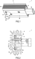
- the object of the invention relates to a light-emitting device 1 using a high-power emitting diode 2, the light of which is intended to be recovered by a bundle or a strand 3 of optical fibers in order to constitute together a light emission system I.
- This diode 2 is a light-emitting diode of any type known per se.
- the bundle 3 with optical fiber(s) can comprise one or more optical fibers of any kind.
- Such a light-emitting device 1 can be used for all types of lighting and in particular in automobiles.
- the light-emitting device 1 comprises a mounting support 4 for the diode 2.
- This support 4 such as a printed circuit board, has an internal surface 4i and an external surface 4e.
- the light-emitting device 1 also comprises a heat dissipation shell 6 in contact with the support 4 of the diode 2 and in particular with the external surface 4e.
- the heat dissipation shell 6 is in the form of a U-section profile, having a bottom 6f from which rise on either side, two side wings 6l.
- This heat dissipation shell 6 is provided externally with heat dissipation fins 6a while the shell 6 internally has flat or smooth internal faces.
- the internal face of the bottom 6f of this heat dissipation shell 6 is in contact with the fourth external surface of the support 4.
- the support 4 is fixed to the bottom 6f of the shell by any suitable means.
- the light-emitting device 1 comprises a casing 8 in which is mounted an optical coupling element 9 adapted to couple the light emitted by the diode 2, into the input surface of the bundle of optical fibers 3.
- the casing 8 has a main wall 8p from which rise on either side, two side branches 8b.
- the box 8 dimensions are adapted so that the heat dissipation shell 6 can be fitted onto the box 8 so that the bottom 6f of this heat dissipation shell 6 is located positioned opposite the main wall 8p to close the box.
- the side wings 6l of the heat dissipation shell extend on either side of the side branches 8b of the case.
- the box 8 also comprises at each of its ends, a transverse closure wall 8t, one of which is equipped with an electrical power connector 8c.
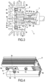
- the main wall 8p of the box 8 is provided with a connection sleeve 8r internally delimiting a well 8d for receiving the beam 3 ( Fig. 3 ).
- the housing 8 includes a holding or positioning system 11 for the optical coupling element 9 which is mounted between the housing 8 and the support 4. In the mounted position, the optical coupling element 9 is positioned to recover the light produced by the diode 2 and bring it to the beam 3.
- the optical coupling element 9 comprises a ninth input surface for the light exiting from the diode 2 and positioned opposite or opposite screw of the emitting surface of the diode 2.
- the optical coupling element 9 also includes an output surface 9s for the light, positioned in the well 8d for receiving the beam 3 so that the light can be recovered by the beam 3 .
- the optical coupling element 9 comprises a body of revolution 9r with a section increasing from its entry surface 9e.
- the body of revolution 9r has, opposite its entry surface 9e, a positioning collar 9c extending transversely with respect to the body of revolution.
- This positioning collar 9c has, in its central part coming in the extension of the body of revolution 9r, the exit surface 9s for the light ( Fig. 5 ).
- the central part of the positioning collar 9c is extended transversely by a peripheral part 9i which projects transversely all around the body of revolution 9r.
- the positioning flange 9c is intended to be mounted in the housing 8.
- the housing 8 comprises, as a positioning system 11, a housing of complementary shape to the positioning flange 9c.
- the positioning flange 9c has a prismatic shape cooperating with the housing of complementary prismatic shape.
- the positioning collar 9c has two straight edges connected on either side by arcuate edges.
- the housing 11 opens in its central part, into the well 8d for receiving the beam 3. At least part of the peripheral part 9i of the positioning collar 9c comes to rest in the housing 11 while the central defining the output surface 9s opens into the well 8d for receiving the beam 3.
- the housing 11 is delimited by a bottom 8k arranged in the housing 8 and which can serve as an abutment surface for the optical coupling element 9. This bottom 8k thus makes it possible to maintain the optical coupling element 9 in position in the absence in particular of the beam 3 as will be explained in the remainder of the description.
- the optical coupling element 9 also comprises a bearing surface 9a with the support 4 so as to position the input surface 9e of the optical coupling element in a position to optimize the coupling of light.
- the optical coupling element 9 is thus interposed in abutment between the support 4 and the housing 8.
- the optical coupling element 9 comprises a support body 9p extending from the peripheral part 9i of the positioning collar 9c, substantially parallel to the body of revolution 9r. This support body has at its free end opposite to the positioning collar 9c, the support surface 9a with the support.
- this support body is made by at least two and in the illustrated example, by four legs 9p extending from the positioning flange 9c, outside the exit surface 9s of the optical coupling element 9. These tabs 9p are regularly distributed angularly around the body of revolution 9r. These legs 9p have at their ends the bearing surface 9a with the support 4.
- At least one and for example two symmetrically opposite tabs 9p are each provided at its end with a centering finger 9d engaged in a hole 4t provided in the support 4.
- the casing 8 and the heat dissipation shell 6 are assembled together by a fixing device 13 which allows the mounting of the optical coupling element 9 between the casing and the support 4.
- the fixing device 13 can be made in any way appropriate.
- the fixing device 13 between the casing 8 and the heat dissipation shell 9 comprises assembly screws 13 passing through the casing to be anchored in the shell 9.
- three assembly screws 13 are used but it is clear that the number of screws can be different.
- the fixing device 13 can be of a different nature, such as the snap-on type, for example.
- a seal 15 is interposed between the casing 4 and the heat dissipation shell 9.
- This seal 15 is mounted in a groove 8g provided at the end of the two lateral branches 8b and closing transverse walls 8t. This seal 15 thus rests on the bottom 6f of the heat dissipation shell 6.
- the support 4 for mounting the emitter diode 2 is connected by connections 16 to a printed circuit board 17 making it possible to control the operation of the diode.
- This card 17 is provided with lugs 18 opening into the power supply connector 8c for connection to a cable, not shown.
- This card 17 which is equipped with electronic components for the operation in particular of the diode, is not directly subjected to the heat produced by the diode.
- Such a light-emitting device 1 makes it possible to position the optical coupling element 9 in a fixed and precise manner with respect to the diode 2, ensuring optimum coupling of the light emitted by the diode 2.
- the input surface 9th of the optical coupling element 9 is positioned at a fixed determined distance with respect to the diode 2.
- the optical coupling element 9 remains in this position regardless of the mechanical stresses that the housing is subjected to.
- this device 1 allows good dissipation of the heat emitted by the diode.
- This light emission device 1 is capable of receiving a beam 3 to constitute a light emission system I.
- the beam 3 is provided with a sleeve 22 positioned in the well 8d of the housing to capture the light emitted by the output surface 9s of the optical coupling element 9.
- the sleeve 22 has a transverse face 22a resting on the peripheral part 9i of the positioning collar 9c, outside the exit surface 9s.
- the bundle of optical fibers 3 is positioned facing the exit surface 9s of the optical coupling element 9.
- the bundle 3 is positioned in contact with the exit surface 9s of the optical coupling element 9 insofar as the beam extends as far as the transverse face 22a of the sleeve 22.
- Such an arrangement allows an optimized coupling of the light.
- the sleeve 22 grouping together the beam 3 has a translation blocking system 23 allowing the stopping of the depression of the sleeve 22 inside the well 8d for receiving the beam 3.
- the translation blocking system 23 thus ensures a connection at least in translation between the sleeve 22 and the housing 8.
- This translation blocking system 23 makes it possible to block the depression of the sleeve 22 so that the sleeve 22 or even the beam 3 is in contact with the optical coupling element 9 which can thus no longer be in contact with the 8k background.
- this translation blocking system 23 can be achieved by lugs carried by the sleeve 22 and intended to engage in orifices provided in the connection sleeve 8r.
- the translation locking system 23 can be produced differently by gluing or a circlip for example.
- the sleeve 22 bears against the optical coupling element 9 and forms a part independent of the optical coupling element 9.
- the Fig. 7 illustrates another embodiment in which the sleeve 22 and the optical coupling element 9 form a single piece.
- the sleeve 22 and the optical coupling element 9 made in the extension of the sleeve 22 are molded onto the bundle 3.
- the element optical coupling 9 and the sleeve 22 are molded onto the beam 3 so that the beam 3 is in contact with the exit surface 9s of the optical coupling element 9.
- Fig. 8 illustrates another alternative embodiment in which the sleeve 22 and the optical coupling element 9 are two parts linked together.
- the sleeve 22 and the optical coupling element 9 are integral by overmoulding.
- the optical coupling element 9 is molded onto the end of the sleeve 22.
- the optical coupling element 9 comprises for example an annular ring 9i extending axially from the collar positioning 9c and provided at its end with a flange 9t which is anchored on the outside of the sleeve 22.
- the beam 3 is in contact with the output surface 9s of the optical coupling element 9 .
- the beam 3 is in contact with the output surface 9s of the optical coupling element 9 making it possible to optimize the optical coupling.
- the beam 3 may not be in contact with the exit surface 9s of the optical coupling element 9.
- the beam 3 is mounted integral with the optical coupling element 9.
- Such an assembly makes it possible to adapt to different types of light-emitting devices.
Landscapes
- Physics & Mathematics (AREA)
- General Physics & Mathematics (AREA)
- Optics & Photonics (AREA)
- Optical Couplings Of Light Guides (AREA)
- Led Devices (AREA)
- Optical Radar Systems And Details Thereof (AREA)
Claims (10)
- Lichtemissionssystem, umfassend:- eine Vorrichtung zur Lichtemission (1) mit Hilfe einer emittierenden Diode (2), welche auf einem Träger (4) befestigt ist und deren Licht durch ein optisches Faserbündel (3) zurückgewonnen werden soll, wobei die Vorrichtung ein Gehäuse (8) umfasst, das mit einem Positionierungssystem (11) für ein optisches Kopplungselement (9) versehen ist, welches eine Austrittsfläche (9s) besitzt, die in eine Vertiefung (8d) zur Aufnahme des Bündels (3) mündet, wobei das optische Kopplungselement (9) eine Auflagefläche (9a) mit dem Träger (4), welche die Eintrittsfläche (9c) des optischen Kopplungselements (9) gegenüber der Diode (2) positioniert, umfasst, wobei der Träger (4) der Diode in Kontakt mit einer Wärmeableitungshülle (6) angeordnet ist, die über eine Befestigungsvorrichtung (3), welche die Montage des optischen Kopplungselements (9) sicherstellt, an dem Gehäuse (8) angebracht ist,- und wobei das Bündel (3) in der Vertiefung (8d) des Gehäuses positioniert ist, um das über die Austrittsfläche des optischen Kopplungselements emittierte Licht aufzufangen, wobei das Lichtemissionssystem dadurch gekennzeichnet ist, dass das Bündel (3) mit einer Hülse (22) versehen ist, die eine Querfläche (22a) in Anlage an dem optischen Kopplungselement (9) außerhalb der Austrittsfläche (9s) aufweist, wobei die Hülse (22) ein Translationsblockiersystem (23) umfasst.
- Lichtemissionssystem nach Anspruch 1, wonach das optische Kopplungselement (9) einen Rotationskörper (9r) mit einem von seiner Eintrittsfläche (9e) aus zunehmenden Querschnitt umfasst, wobei der, Rotationskörper (9r) einen Positionierungskragen (9r) aufweist, der sich um den Rotationskörper (9r) herum durchgehend vorspringend erstreckt und eine Austrittsseite (9s) besitzt, die in ihrem mittleren Teil die Austrittsfläche für das Licht sowie außerhalb dieser Austrittsfläche Laschen (9p) aufweist, die sich vorspringend erstrecken, um an ihren Enden die Auflagefläche (9a) mit dem Träger (4) der emittierenden Diode aufzuweisen.
- Lichtemissionssystem nach Anspruch 2, wonach wenigstens eine Lasche (9p) an ihrem Ende mit einem Zentrierfinger (9d) versehen ist, der in ein in dem Träger (4) ausgebildetes Loch (4t) eingreift.
- Lichtemissionssystem nach einem der Ansprüche 2 bis 3, wonach das Positionierungssystem (11) für das optische Kopplungselement (9) eine Aufnahme mit prismatischer Form umfasst, die mit dem Kragen (9c) des optischen Kopplungselements (9), der eine ergänzende Form aufweist, zusammenwirkt.
- Lichtemissionssystem nach einem der vorhergehenden Ansprüche, wonach zwischen dem Gehäuse (8) und der Wärmeableitungshülle (6) eine Dichtung (15) eingesetzt ist.
- Lichtemissionssystem nach einem der vorhergehenden Ansprüche, wonach die Befestigungsvorrichtung (13) zwischen dem Gehäuse (8) und der Wärmeableitungshülle (6) Montageschrauben umfasst, welche das Gehäuse durchgreifen, um sich in der Hülle zu verankern.
- Lichtemissionssystem nach einem der vorhergehenden Ansprüche, wonach der Träger (4) zum Anbringen der emittierenden Diode (2) über Verbindungen (16) mit einer Leiterplatte (17) zum Steuern des Betriebs der Diode verbunden ist.
- Lichtemissionssystem nach einem der vorhergehenden Ansprüche, wonach die Hülse (22) und das optische Kopplungselement (9) ein einziges Teil bilden.
- Lichtemissionssystem nach einem der Ansprüche 1 bis 7, wonach die Hülse (22) und das optische Kopplungselement (9) durch Anformen fest miteinander verbunden sind.
- Lichtemissionssystem nach einem der vorhergehenden Ansprüche, wonach das Bündel (3) mit der Austrittsfläche (9s) des optischen Kopplungselements (9) in Kontakt ist.
Applications Claiming Priority (2)
| Application Number | Priority Date | Filing Date | Title |
|---|---|---|---|
| FR1901195A FR3092437B1 (fr) | 2019-02-06 | 2019-02-06 | Dispositif d’émission lumineuse à l’aide d’une LED de forte puissance |
| PCT/FR2020/050212 WO2020161444A1 (fr) | 2019-02-06 | 2020-02-06 | Système d'émission lumineuse a l'aide d'une led de forte puissance |
Publications (2)
| Publication Number | Publication Date |
|---|---|
| EP3921680A1 EP3921680A1 (de) | 2021-12-15 |
| EP3921680B1 true EP3921680B1 (de) | 2023-02-15 |
Family
ID=67185270
Family Applications (1)
| Application Number | Title | Priority Date | Filing Date |
|---|---|---|---|
| EP20707159.8A Active EP3921680B1 (de) | 2019-02-06 | 2020-02-06 | Lichtemissionsvorrichtung mit einer hochleistungs-led |
Country Status (4)
| Country | Link |
|---|---|
| EP (1) | EP3921680B1 (de) |
| ES (1) | ES2943060T3 (de) |
| FR (1) | FR3092437B1 (de) |
| WO (1) | WO2020161444A1 (de) |
Families Citing this family (1)
| Publication number | Priority date | Publication date | Assignee | Title |
|---|---|---|---|---|
| FR3128765B1 (fr) * | 2021-10-29 | 2023-11-17 | Valeo Vision | Module optique d’un dispositif lumineux d’un véhicule automobile |
Family Cites Families (7)
| Publication number | Priority date | Publication date | Assignee | Title |
|---|---|---|---|---|
| US6547423B2 (en) | 2000-12-22 | 2003-04-15 | Koninklijke Phillips Electronics N.V. | LED collimation optics with improved performance and reduced size |
| US6945674B2 (en) * | 2002-07-16 | 2005-09-20 | Ccs, Inc. | Light irradiating unit |
| US7217022B2 (en) * | 2004-08-31 | 2007-05-15 | Opto Technology, Inc. | Optic fiber LED light source |
| ATE541206T1 (de) * | 2004-11-30 | 2012-01-15 | Ccs Inc | Leuchtvorrichtung mit hochleistungs-led zur produkt-kontrolle |
| DE102005033709B4 (de) * | 2005-03-16 | 2021-12-16 | OSRAM Opto Semiconductors Gesellschaft mit beschränkter Haftung | Lichtemittierendes Modul |
| WO2007013563A1 (ja) * | 2005-07-29 | 2007-02-01 | Ccs Inc. | 光学ユニット及び光照射装置 |
| DE102009049057B4 (de) | 2009-10-12 | 2018-10-25 | Osram Gmbh | LED-Modul, Verfahren zum Betreiben dieses LED-Moduls und Beleuchtungsvorrichtung mit diesem LED-Modul |
-
2019
- 2019-02-06 FR FR1901195A patent/FR3092437B1/fr not_active Expired - Fee Related
-
2020
- 2020-02-06 ES ES20707159T patent/ES2943060T3/es active Active
- 2020-02-06 EP EP20707159.8A patent/EP3921680B1/de active Active
- 2020-02-06 WO PCT/FR2020/050212 patent/WO2020161444A1/fr not_active Ceased
Also Published As
| Publication number | Publication date |
|---|---|
| WO2020161444A1 (fr) | 2020-08-13 |
| EP3921680A1 (de) | 2021-12-15 |
| FR3092437A1 (fr) | 2020-08-07 |
| ES2943060T3 (es) | 2023-06-08 |
| FR3092437B1 (fr) | 2021-04-30 |
Similar Documents
| Publication | Publication Date | Title |
|---|---|---|
| EP4065882B1 (de) | Lichtmodul eines kraftfahrzeugs, das mit einem optischen element ausgestattet ist | |
| FR3002794A1 (fr) | Dispositif d'eclairage et/ou de signalisation pour vehicule automobile,comportant un guide de lumiere | |
| EP3884206B1 (de) | Multifunktionales lichtmodul mit zwei flachen lichtleitern | |
| FR2917348A1 (fr) | Dispositif d'eclairage et/ou de signalisation pour vehicule automobile, a source de lumiere amovible. | |
| WO2016097322A1 (fr) | Dispositif d'eclairage et/ou de signalisation comportant un guide de lumiere | |
| FR2994788A1 (fr) | Module d'eclairage comprenant un dispositif de commande maintenu de maniere amovible sur un support | |
| EP2966344A1 (de) | Optisches modul mit linse für kfz-scheinwerfer | |
| EP3921680B1 (de) | Lichtemissionsvorrichtung mit einer hochleistungs-led | |
| KR102691206B1 (ko) | 이중-재료 전달 광학 요소 | |
| EP3815972B1 (de) | Träger- und vrebindungsvorrichtung einer elektronischen karte für die steuerung eines licht- oder signalisierungsmoduls eines kraftfahrzeugs | |
| EP3222903B1 (de) | Leuchtvorrichtung für kraftfahrzeug, und entsprechendes montageverfahren | |
| FR3084479A1 (fr) | Dispositif electronique et assemblage, incluant des guides d'ondes optiques | |
| EP3254017B1 (de) | Reflektorvorrichtung für ein lichtmodul mit elektromagnetischer abschirmung | |
| EP3839331B1 (de) | Kraftfahrzeugleuchtmodul mit zwei lichtquellen | |
| FR3088869A1 (fr) | Dispositif de pré-positionnement et de maintien d’un élément sur un boitier | |
| WO2018050974A1 (fr) | Luminaire connectable à un réseau de télécommunication. | |
| EP4174367A1 (de) | Optisches modul einer leuchtvorrichtung eines kraftfahrzeugs | |
| EP3887716B1 (de) | Beleuchtungsvorrichtung | |
| EP2995849A1 (de) | Leuchtmodul, das eine organische elektrolumineszenzdiode umfasst | |
| FR3069207A1 (fr) | Dispositif d’eclairage a piece en materiau transparent integrant des moyens d’eclairage assurant une fonction photometrique | |
| FR3139636A1 (fr) | système d'émission lumineuse | |
| EP3190004B1 (de) | Kabelführungsvorrichtung für eine leuchtvorrichtung eines kraftfahrzeugs | |
| FR2895785A1 (fr) | Dispositif lumineux pour panneaux de signalisation | |
| FR3145027A1 (fr) | Bloc optique pour véhicule avec guide de lumière tubulaire partiellement encapsulé dans une enveloppe opaque | |
| FR3152144A1 (fr) | Support pour dispositif de détection notamment pour véhicule automobile et ensemble de détection correspondant |
Legal Events
| Date | Code | Title | Description |
|---|---|---|---|
| STAA | Information on the status of an ep patent application or granted ep patent |
Free format text: STATUS: UNKNOWN |
|
| STAA | Information on the status of an ep patent application or granted ep patent |
Free format text: STATUS: THE INTERNATIONAL PUBLICATION HAS BEEN MADE |
|
| PUAI | Public reference made under article 153(3) epc to a published international application that has entered the european phase |
Free format text: ORIGINAL CODE: 0009012 |
|
| STAA | Information on the status of an ep patent application or granted ep patent |
Free format text: STATUS: REQUEST FOR EXAMINATION WAS MADE |
|
| 17P | Request for examination filed |
Effective date: 20210809 |
|
| AK | Designated contracting states |
Kind code of ref document: A1 Designated state(s): AL AT BE BG CH CY CZ DE DK EE ES FI FR GB GR HR HU IE IS IT LI LT LU LV MC MK MT NL NO PL PT RO RS SE SI SK SM TR |
|
| DAV | Request for validation of the european patent (deleted) | ||
| DAX | Request for extension of the european patent (deleted) | ||
| GRAP | Despatch of communication of intention to grant a patent |
Free format text: ORIGINAL CODE: EPIDOSNIGR1 |
|
| STAA | Information on the status of an ep patent application or granted ep patent |
Free format text: STATUS: GRANT OF PATENT IS INTENDED |
|
| INTG | Intention to grant announced |
Effective date: 20220912 |
|
| GRAS | Grant fee paid |
Free format text: ORIGINAL CODE: EPIDOSNIGR3 |
|
| GRAA | (expected) grant |
Free format text: ORIGINAL CODE: 0009210 |
|
| STAA | Information on the status of an ep patent application or granted ep patent |
Free format text: STATUS: THE PATENT HAS BEEN GRANTED |
|
| AK | Designated contracting states |
Kind code of ref document: B1 Designated state(s): AL AT BE BG CH CY CZ DE DK EE ES FI FR GB GR HR HU IE IS IT LI LT LU LV MC MK MT NL NO PL PT RO RS SE SI SK SM TR |
|
| REG | Reference to a national code |
Ref country code: CH Ref legal event code: EP Ref country code: GB Ref legal event code: FG4D Free format text: NOT ENGLISH |
|
| REG | Reference to a national code |
Ref country code: DE Ref legal event code: R096 Ref document number: 602020008109 Country of ref document: DE |
|
| REG | Reference to a national code |
Ref country code: AT Ref legal event code: REF Ref document number: 1548513 Country of ref document: AT Kind code of ref document: T Effective date: 20230315 Ref country code: IE Ref legal event code: FG4D Free format text: LANGUAGE OF EP DOCUMENT: FRENCH |
|
| REG | Reference to a national code |
Ref country code: ES Ref legal event code: FG2A Ref document number: 2943060 Country of ref document: ES Kind code of ref document: T3 Effective date: 20230608 |
|
| REG | Reference to a national code |
Ref country code: LT Ref legal event code: MG9D |
|
| P01 | Opt-out of the competence of the unified patent court (upc) registered |
Effective date: 20230517 |
|
| REG | Reference to a national code |
Ref country code: NL Ref legal event code: MP Effective date: 20230215 |
|
| REG | Reference to a national code |
Ref country code: AT Ref legal event code: MK05 Ref document number: 1548513 Country of ref document: AT Kind code of ref document: T Effective date: 20230215 |
|
| PG25 | Lapsed in a contracting state [announced via postgrant information from national office to epo] |
Ref country code: RS Free format text: LAPSE BECAUSE OF FAILURE TO SUBMIT A TRANSLATION OF THE DESCRIPTION OR TO PAY THE FEE WITHIN THE PRESCRIBED TIME-LIMIT Effective date: 20230215 Ref country code: PT Free format text: LAPSE BECAUSE OF FAILURE TO SUBMIT A TRANSLATION OF THE DESCRIPTION OR TO PAY THE FEE WITHIN THE PRESCRIBED TIME-LIMIT Effective date: 20230615 Ref country code: NO Free format text: LAPSE BECAUSE OF FAILURE TO SUBMIT A TRANSLATION OF THE DESCRIPTION OR TO PAY THE FEE WITHIN THE PRESCRIBED TIME-LIMIT Effective date: 20230515 Ref country code: NL Free format text: LAPSE BECAUSE OF FAILURE TO SUBMIT A TRANSLATION OF THE DESCRIPTION OR TO PAY THE FEE WITHIN THE PRESCRIBED TIME-LIMIT Effective date: 20230215 Ref country code: LV Free format text: LAPSE BECAUSE OF FAILURE TO SUBMIT A TRANSLATION OF THE DESCRIPTION OR TO PAY THE FEE WITHIN THE PRESCRIBED TIME-LIMIT Effective date: 20230215 Ref country code: LT Free format text: LAPSE BECAUSE OF FAILURE TO SUBMIT A TRANSLATION OF THE DESCRIPTION OR TO PAY THE FEE WITHIN THE PRESCRIBED TIME-LIMIT Effective date: 20230215 Ref country code: HR Free format text: LAPSE BECAUSE OF FAILURE TO SUBMIT A TRANSLATION OF THE DESCRIPTION OR TO PAY THE FEE WITHIN THE PRESCRIBED TIME-LIMIT Effective date: 20230215 Ref country code: AT Free format text: LAPSE BECAUSE OF FAILURE TO SUBMIT A TRANSLATION OF THE DESCRIPTION OR TO PAY THE FEE WITHIN THE PRESCRIBED TIME-LIMIT Effective date: 20230215 |
|
| PG25 | Lapsed in a contracting state [announced via postgrant information from national office to epo] |
Ref country code: SE Free format text: LAPSE BECAUSE OF FAILURE TO SUBMIT A TRANSLATION OF THE DESCRIPTION OR TO PAY THE FEE WITHIN THE PRESCRIBED TIME-LIMIT Effective date: 20230215 Ref country code: PL Free format text: LAPSE BECAUSE OF FAILURE TO SUBMIT A TRANSLATION OF THE DESCRIPTION OR TO PAY THE FEE WITHIN THE PRESCRIBED TIME-LIMIT Effective date: 20230215 Ref country code: IS Free format text: LAPSE BECAUSE OF FAILURE TO SUBMIT A TRANSLATION OF THE DESCRIPTION OR TO PAY THE FEE WITHIN THE PRESCRIBED TIME-LIMIT Effective date: 20230615 Ref country code: GR Free format text: LAPSE BECAUSE OF FAILURE TO SUBMIT A TRANSLATION OF THE DESCRIPTION OR TO PAY THE FEE WITHIN THE PRESCRIBED TIME-LIMIT Effective date: 20230516 Ref country code: FI Free format text: LAPSE BECAUSE OF FAILURE TO SUBMIT A TRANSLATION OF THE DESCRIPTION OR TO PAY THE FEE WITHIN THE PRESCRIBED TIME-LIMIT Effective date: 20230215 |
|
| PG25 | Lapsed in a contracting state [announced via postgrant information from national office to epo] |
Ref country code: SM Free format text: LAPSE BECAUSE OF FAILURE TO SUBMIT A TRANSLATION OF THE DESCRIPTION OR TO PAY THE FEE WITHIN THE PRESCRIBED TIME-LIMIT Effective date: 20230215 Ref country code: RO Free format text: LAPSE BECAUSE OF FAILURE TO SUBMIT A TRANSLATION OF THE DESCRIPTION OR TO PAY THE FEE WITHIN THE PRESCRIBED TIME-LIMIT Effective date: 20230215 Ref country code: EE Free format text: LAPSE BECAUSE OF FAILURE TO SUBMIT A TRANSLATION OF THE DESCRIPTION OR TO PAY THE FEE WITHIN THE PRESCRIBED TIME-LIMIT Effective date: 20230215 Ref country code: DK Free format text: LAPSE BECAUSE OF FAILURE TO SUBMIT A TRANSLATION OF THE DESCRIPTION OR TO PAY THE FEE WITHIN THE PRESCRIBED TIME-LIMIT Effective date: 20230215 Ref country code: CZ Free format text: LAPSE BECAUSE OF FAILURE TO SUBMIT A TRANSLATION OF THE DESCRIPTION OR TO PAY THE FEE WITHIN THE PRESCRIBED TIME-LIMIT Effective date: 20230215 |
|
| REG | Reference to a national code |
Ref country code: DE Ref legal event code: R097 Ref document number: 602020008109 Country of ref document: DE |
|
| PG25 | Lapsed in a contracting state [announced via postgrant information from national office to epo] |
Ref country code: SK Free format text: LAPSE BECAUSE OF FAILURE TO SUBMIT A TRANSLATION OF THE DESCRIPTION OR TO PAY THE FEE WITHIN THE PRESCRIBED TIME-LIMIT Effective date: 20230215 |
|
| PLBE | No opposition filed within time limit |
Free format text: ORIGINAL CODE: 0009261 |
|
| STAA | Information on the status of an ep patent application or granted ep patent |
Free format text: STATUS: NO OPPOSITION FILED WITHIN TIME LIMIT |
|
| 26N | No opposition filed |
Effective date: 20231116 |
|
| PG25 | Lapsed in a contracting state [announced via postgrant information from national office to epo] |
Ref country code: SI Free format text: LAPSE BECAUSE OF FAILURE TO SUBMIT A TRANSLATION OF THE DESCRIPTION OR TO PAY THE FEE WITHIN THE PRESCRIBED TIME-LIMIT Effective date: 20230215 |
|
| PGFP | Annual fee paid to national office [announced via postgrant information from national office to epo] |
Ref country code: ES Payment date: 20240306 Year of fee payment: 5 |
|
| PGFP | Annual fee paid to national office [announced via postgrant information from national office to epo] |
Ref country code: DE Payment date: 20240213 Year of fee payment: 5 |
|
| PGFP | Annual fee paid to national office [announced via postgrant information from national office to epo] |
Ref country code: IT Payment date: 20240207 Year of fee payment: 5 Ref country code: FR Payment date: 20240221 Year of fee payment: 5 |
|
| PG25 | Lapsed in a contracting state [announced via postgrant information from national office to epo] |
Ref country code: MC Free format text: LAPSE BECAUSE OF FAILURE TO SUBMIT A TRANSLATION OF THE DESCRIPTION OR TO PAY THE FEE WITHIN THE PRESCRIBED TIME-LIMIT Effective date: 20230215 |
|
| REG | Reference to a national code |
Ref country code: CH Ref legal event code: PL |
|
| PG25 | Lapsed in a contracting state [announced via postgrant information from national office to epo] |
Ref country code: LU Free format text: LAPSE BECAUSE OF NON-PAYMENT OF DUE FEES Effective date: 20240206 |
|
| PG25 | Lapsed in a contracting state [announced via postgrant information from national office to epo] |
Ref country code: CH Free format text: LAPSE BECAUSE OF NON-PAYMENT OF DUE FEES Effective date: 20240229 |
|
| GBPC | Gb: european patent ceased through non-payment of renewal fee |
Effective date: 20240206 |
|
| PG25 | Lapsed in a contracting state [announced via postgrant information from national office to epo] |
Ref country code: LU Free format text: LAPSE BECAUSE OF NON-PAYMENT OF DUE FEES Effective date: 20240206 Ref country code: CH Free format text: LAPSE BECAUSE OF NON-PAYMENT OF DUE FEES Effective date: 20240229 |
|
| PG25 | Lapsed in a contracting state [announced via postgrant information from national office to epo] |
Ref country code: BG Free format text: LAPSE BECAUSE OF FAILURE TO SUBMIT A TRANSLATION OF THE DESCRIPTION OR TO PAY THE FEE WITHIN THE PRESCRIBED TIME-LIMIT Effective date: 20230215 |
|
| PG25 | Lapsed in a contracting state [announced via postgrant information from national office to epo] |
Ref country code: BG Free format text: LAPSE BECAUSE OF FAILURE TO SUBMIT A TRANSLATION OF THE DESCRIPTION OR TO PAY THE FEE WITHIN THE PRESCRIBED TIME-LIMIT Effective date: 20230215 |
|
| REG | Reference to a national code |
Ref country code: BE Ref legal event code: MM Effective date: 20240229 |
|
| PG25 | Lapsed in a contracting state [announced via postgrant information from national office to epo] |
Ref country code: BE Free format text: LAPSE BECAUSE OF NON-PAYMENT OF DUE FEES Effective date: 20240229 |
|
| PG25 | Lapsed in a contracting state [announced via postgrant information from national office to epo] |
Ref country code: GB Free format text: LAPSE BECAUSE OF NON-PAYMENT OF DUE FEES Effective date: 20240206 |
|
| PG25 | Lapsed in a contracting state [announced via postgrant information from national office to epo] |
Ref country code: IE Free format text: LAPSE BECAUSE OF NON-PAYMENT OF DUE FEES Effective date: 20240206 |
|
| PG25 | Lapsed in a contracting state [announced via postgrant information from national office to epo] |
Ref country code: IE Free format text: LAPSE BECAUSE OF NON-PAYMENT OF DUE FEES Effective date: 20240206 Ref country code: GB Free format text: LAPSE BECAUSE OF NON-PAYMENT OF DUE FEES Effective date: 20240206 Ref country code: BE Free format text: LAPSE BECAUSE OF NON-PAYMENT OF DUE FEES Effective date: 20240229 |
|
| PG25 | Lapsed in a contracting state [announced via postgrant information from national office to epo] |
Ref country code: CY Free format text: LAPSE BECAUSE OF FAILURE TO SUBMIT A TRANSLATION OF THE DESCRIPTION OR TO PAY THE FEE WITHIN THE PRESCRIBED TIME-LIMIT; INVALID AB INITIO Effective date: 20200206 |
|
| REG | Reference to a national code |
Ref country code: DE Ref legal event code: R119 Ref document number: 602020008109 Country of ref document: DE |
|
| PG25 | Lapsed in a contracting state [announced via postgrant information from national office to epo] |
Ref country code: HU Free format text: LAPSE BECAUSE OF FAILURE TO SUBMIT A TRANSLATION OF THE DESCRIPTION OR TO PAY THE FEE WITHIN THE PRESCRIBED TIME-LIMIT; INVALID AB INITIO Effective date: 20200206 |
|
| PG25 | Lapsed in a contracting state [announced via postgrant information from national office to epo] |
Ref country code: TR Free format text: LAPSE BECAUSE OF FAILURE TO SUBMIT A TRANSLATION OF THE DESCRIPTION OR TO PAY THE FEE WITHIN THE PRESCRIBED TIME-LIMIT Effective date: 20230215 |
|
| PG25 | Lapsed in a contracting state [announced via postgrant information from national office to epo] |
Ref country code: DE Free format text: LAPSE BECAUSE OF NON-PAYMENT OF DUE FEES Effective date: 20250902 |
|
| PG25 | Lapsed in a contracting state [announced via postgrant information from national office to epo] |
Ref country code: IT Free format text: LAPSE BECAUSE OF NON-PAYMENT OF DUE FEES Effective date: 20250206 Ref country code: FR Free format text: LAPSE BECAUSE OF NON-PAYMENT OF DUE FEES Effective date: 20250228 |
|
| REG | Reference to a national code |
Ref country code: ES Ref legal event code: FD2A Effective date: 20260326 |
|
| PG25 | Lapsed in a contracting state [announced via postgrant information from national office to epo] |
Ref country code: ES Free format text: LAPSE BECAUSE OF NON-PAYMENT OF DUE FEES Effective date: 20250207 |