EP3921677B1 - Strahlkollimationslinse - Google Patents
Strahlkollimationslinse Download PDFInfo
- Publication number
- EP3921677B1 EP3921677B1 EP19805675.6A EP19805675A EP3921677B1 EP 3921677 B1 EP3921677 B1 EP 3921677B1 EP 19805675 A EP19805675 A EP 19805675A EP 3921677 B1 EP3921677 B1 EP 3921677B1
- Authority
- EP
- European Patent Office
- Prior art keywords
- collimating lens
- biconvex
- beam collimating
- area
- laser light
- Prior art date
- Legal status (The legal status is an assumption and is not a legal conclusion. Google has not performed a legal analysis and makes no representation as to the accuracy of the status listed.)
- Active
Links
Images


Classifications
-
- G—PHYSICS
- G02—OPTICS
- G02B—OPTICAL ELEMENTS, SYSTEMS OR APPARATUS
- G02B19/00—Condensers, e.g. light collectors or similar non-imaging optics
- G02B19/0004—Condensers, e.g. light collectors or similar non-imaging optics characterised by the optical means employed
- G02B19/0009—Condensers, e.g. light collectors or similar non-imaging optics characterised by the optical means employed having refractive surfaces only
- G02B19/0014—Condensers, e.g. light collectors or similar non-imaging optics characterised by the optical means employed having refractive surfaces only at least one surface having optical power
-
- G—PHYSICS
- G02—OPTICS
- G02B—OPTICAL ELEMENTS, SYSTEMS OR APPARATUS
- G02B27/00—Optical systems or apparatus not provided for by any of the groups G02B1/00 - G02B26/00, G02B30/00
- G02B27/30—Collimators
-
- G—PHYSICS
- G02—OPTICS
- G02B—OPTICAL ELEMENTS, SYSTEMS OR APPARATUS
- G02B19/00—Condensers, e.g. light collectors or similar non-imaging optics
- G02B19/0033—Condensers, e.g. light collectors or similar non-imaging optics characterised by the use
- G02B19/0047—Condensers, e.g. light collectors or similar non-imaging optics characterised by the use for use with a light source
- G02B19/0052—Condensers, e.g. light collectors or similar non-imaging optics characterised by the use for use with a light source the light source comprising a laser diode
-
- G—PHYSICS
- G02—OPTICS
- G02B—OPTICAL ELEMENTS, SYSTEMS OR APPARATUS
- G02B3/00—Simple or compound lenses
- G02B3/02—Simple or compound lenses with non-spherical faces
-
- G—PHYSICS
- G02—OPTICS
- G02B—OPTICAL ELEMENTS, SYSTEMS OR APPARATUS
- G02B3/00—Simple or compound lenses
- G02B3/02—Simple or compound lenses with non-spherical faces
- G02B3/06—Simple or compound lenses with non-spherical faces with cylindrical or toric faces
Definitions
- the invention relates to a light emission device, a beam collimation lens and a method for producing a beam collimation lens.
- Light-emitting devices can be used as high-power diode lasers. Such devices are typically used for light emitters with an asymmetric beam field, which has a so-called “fast axis” and a so-called “slow axis.”
- the fast axis refers to a vertical axis (perpendicular to the semiconductor wafer) that is perpendicular to the slow axis (parallel to the face of the semiconductor wafer).
- the slow axis and the fast axis are perpendicular to each other and orthogonal to the beam propagation direction (z-axis).
- a single emitter with, for example, a dimension on the order of 1 micron has a numerical aperture of 0.5–0.7 in the fast axis and a numerical aperture of 0.05–0.2 in the slow axis.
- the most common fast-axis collimators are plano-cylindrical lenses. These are used to enable low-aberration collimation for fast-axis optics with high numerical aperture.
- collimators are typically made of high-quality glass.
- a high-index material minimizes the maximum lens droop and the degree of surface tilt required to achieve the required refraction.
- homogeneous cylindrical rod lenses i.e., fibers, can also be used.
- a micro-optical element for use with a laser diode stack, the element comprising a plurality of biconvex fast-axis collimator elements formed as a monolithic array.
- the array of inlet lenses is provided on a first surface of the element, and an array of outlet lenses is provided on a second surface of the element, opposite the first surface.
- the arrangement of the inlet and outlet lenses can be adapted to the arrangement of a plurality of individual emitters arranged in a row or in a two-dimensional array.
- the monolithic element can be manufactured from fused silica using laser micromachining.
- Collimation elements with glasses that have high transmission values are mainly used for diode lasers in a wavelength range between 800 and 1000nm.
- High-performance light emitters are also available in a wavelength range below 550 nm, particularly in the 400-500 nm range.
- the selection of glass materials with high transmission values is limited for this wavelength range.
- the beam collimation lens comprises at least one biconvex collimation element and is made of quartz glass.
- the laser light source emits visible laser light, in particular with wavelengths of less than or equal to 550nm, in particular in a wavelength range from 300nm to 550nm, more particularly from 400-500nm.
- Collimation elements made of quartz glass with a refractive index of approximately 1.45 exhibit a low temperature increase up to power levels exceeding 200 W. Beam quality can therefore be maintained over a wide power range.
- the device comprises a plurality of laser light sources.
- the laser light sources can be arranged in a two-dimensional array.
- the laser light sources are arranged in a row next to one another.
- the beam collimation lens preferably has an array of biconvex collimation elements that corresponds to the arrangement of the laser light sources.
- the beam collimation lens is monolithic.
- the biconvex collimating element has an acylindrical shape on the exit side and a cylindrical shape on the entrance side.
- cylindrical shape we mean that the cross-section of the collimating element has a circular shape, while an acylindrical shape is a deviation from the circular segment, for example the shape of a polynomial.
- the entire entrance surface of the biconvex collimating element is convexly curved and/or the entire exit surface of the biconvex collimating element is also convexly curved.
- the surface of the collimating element thus has a simple shape, with no concave or flat partial surfaces. This simplifies the manufacturing process.
- the entrance surface of the entire beam collimation lens is convexly curved and/or the exit surface of the entire beam collimation lens is also convexly curved, in particular when the light emission device comprises a plurality of emitters and a beam collimation lens is used for these multiple emitters.
- the beam collimation lens is rod-shaped.
- Rod-shaped means that the lens is cylindrical and is preferably longer in a direction transverse to the light propagation, namely in the fast-axis direction, than in the direction of light propagation.
- the beam collimation lens can be designed as a biconvex cylinder so that it can be used for a large number of laser light sources arranged in a row.
- the biconvex cylinder can be equipped with a cross-section that has a circular segment on the inlet side.
- Such a beam collimation lens has a simple geometry and can therefore be manufactured easily and cost-effectively, for example in a fiber drawing process.
- Rod-shaped beam collimation lenses can also be easily combined to form a beam collimation lens array for laser light sources arranged in a two-dimensional array, for example by gluing beam collimation lenses together along their long sides.
- the object is achieved by a beam collimation lens, in particular for fast-axis collimation, for a light emission device as described above.
- the beam collimation lens comprises at least one biconvex collimating element and is made of fused silica.
- the entrance surface of the biconvex collimating element is convexly curved, and the exit surface of the biconvex collimating element is also convexly curved, allowing sufficient refraction to be achieved despite the low refractive index of the fused silica.
- the biconvex collimation element has an entrance surface with an area of 0.2mm 2 -10 mm 2 , and/or with a length of 2mm-12mm and/or with a height of 0.1mm-0.85mm.
- the entrance surface refers to the surface of the biconvex collimation element facing the light source.
- the biconvex collimation element has an exit surface with an area of 0.6 mm 2 -30 mm 2 and/or with a length of 2 mm - 12 mm and/or a height of 0.3 mm - 2.5 mm.
- the exit surface refers to the surface of the biconvex collimation element facing away from the light source.
- the biconvex collimation element can have a maximum curvature depth of 0.1mm on the entrance side and/or a maximum curvature depth of 0.5mm on the exit side.
- the biconvex collimation element can have a focal length of 0.2mm to 1.8mm.
- the heights refer to the optically effective ranges. Since the entrance is close to the emitter and there is a large divergence, The optically effective height at the entrance side is smaller than at the exit side. However, the collimation element can be manufactured so that the entrance and exit sides have approximately the same height.
- the above dimensions can also apply to the entire beam collimation lens.
- the beam collimation lens is manufactured using a fiber drawing process.
- the beam collimation lens then preferably has the overall shape of a biconvex cylinder.
- the peripheral surfaces of the beam collimation lens i.e., the surfaces on the cylinder surface, are glossy and precisely shaped.
- the beam collimation lens has no matte surfaces on its circumference, even on the non-optical, upward- and downward-facing peripheral surfaces. Neither saw marks nor traces of a pressing tool are visible on the peripheral surface.
- the non-optical side surfaces transverse to the cylinder axis may be matt due to a separation step and, for example, have saw marks.
- the beam collimation lens is rod-shaped.
- the object is further achieved by a method for producing a beam collimation lens as described above with the following steps.
- a biconvex preform made of quartz glass is provided. Its cross-sectional area is particularly Factor 100 to 10000 larger than the cross-sectional area of the collimation element of the beam collimation lens to be manufactured.
- the preform is manufactured using conventional glass manufacturing processes, such as grinding and polishing.
- the required dimensional accuracy of the lens can be achieved with reasonable effort by scaling it up using conventional production of a large preform.
- the preform is heated, particularly to temperatures of 2000-2200°C.
- the preform which has a shape congruent with the collimation element to be manufactured, is introduced into a suitable furnace.
- the beam collimation lens is peeled off, which results in scaling, i.e., reducing the cross-sectional area. This is typically done using a peel-off device consisting of rollers. The peel force is adjusted to the desired scaling.
- the beam collimation lens When peeled off, after leaving the furnace, the beam collimation lens may still have a temperature of several hundred degrees, which is well below the glass transition temperature, and may have its final cross-section.
- Cooling can take place in air.
- Rod-shaped lenses can then be cut to the desired length.
- rod-shaped beam collimation lenses can then be glued together to form a two-dimensional collimation field.
- the problem is also solved by using a light emission device as described above for processing non-ferrous metals.
- Short wavelengths are suitable for processing non-ferrous metals to enable efficient processing.
- High-power diode lasers with shorter wavelengths can be provided in a simple and cost-effective manner using a beam collimation lens as described above.
- Figure 1 shows a cross-sectional view of a light emission device 1.
- the device 1 comprises several laser light sources 2 arranged in a row, as well as a beam collimation lens 3 for fast-axis collimation.
- the beam collimation lens 3 comprises biconvex collimation elements 4 and is made of quartz glass.
- the laser light sources 1 emit visible laser light with wavelengths of less than 550 nm, in particular in a wavelength range of 300-500 nm.
- the biconvex collimation element 4 has a maximum curvature depth 13 of 0.1 mm on the entrance side 6.
- the biconvex collimation element 4 has a maximum curvature depth 14 of 0.5 mm on the exit side 5.
- the entrance surface 7 has a height 10 of 0.1mm-0.85mm
- the exit surface 8 has a height 12 of 0.3mm-2.5mm.
- the beam collimation lens 3 is preferably manufactured such that a large part of the area 19 between the entrance and exit sides has a constant height 20.
- the contour of the exit side 5 can follow the following polynomial.
- Figure 2 shows a perspective view of a beam collimation lens 3 according to the invention.
- the beam collimation lens 3 is rod-shaped, so that the adjacent biconvex collimation elements 4 merge into one another and form a common entrance surface 7 and exit surface 8.
- the entrance surface 7 and the exit surface 8 have a length 11 of 2 mm-12 mm.
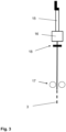
- Figure 3 shows a schematic representation of the production of a beam collimation lens 3.
- a biconvex preform 15 made of quartz glass is provided.
- the preform 15 is heated to temperatures of 2000-2200°C.
- the beam collimation lens 3 is peeled off with a roller peeling device 17, whereby the cross-sectional area is reduced.
- the cross-section is checked with a measuring system 18 after leaving the furnace 16.
- rod-shaped beam collimation lenses 3 are cut to a desired length.
Landscapes
- Physics & Mathematics (AREA)
- General Physics & Mathematics (AREA)
- Optics & Photonics (AREA)
- Optical Couplings Of Light Guides (AREA)
- Laser Beam Processing (AREA)
- Semiconductor Lasers (AREA)
Description
- Die Erfindung betrifft eine Vorrichtung zur Lichtemission, Strahlkollimationslinse und ein Verfahren zum Herstellen einer Strahlkollimationslinse.
- Vorrichtungen zur Lichtemission können als HochleistungsDiodenlaser eingesetzt werden. Typischerweise finden derartige Vorrichtungen Anwendung bei Lichtemittern mit einem asymmetrischen Strahlfeld, das eine sogenannte "Fast-Axis" und eine sogenannte "Slow-Axis" aufweist.
- Die Fast-Axis bezieht sich auf eine vertikale Achse (senkrecht zum Halbleiterwafer), die senkrecht zur Slow-Axis steht (parallel zur Stirnseite der Halbleiterwafer). Die Slow-Axis und die Fast-Axis sind senkrecht zueinander und orthogonal zur Ausbreitungsrichtung des Strahls (z-Achse). Entlang der Ausbreitungsrichtung hat ein Einzelemitter mit zum Beispiel einer Dimension in der Grössenordnung von 1 micron in der Fast Axis eine numerische Apertur von 0.5 - 0.7 und in der Slow-Axis eine numerische Apertur von 0.05 - 0.2.
- Die gebräuchlichsten Kollimatoren für schnelle Achsen sind planzylindrische Linsen. Diese werden verwendet, um eine Kollimation mit geringer Aberration für die Fast-Axis mit hoher numerischer Apertur zu ermöglichen.
- Solche Kollimatoren werden typischerweise aus hochwertigem Glas hergestellt. Ein hochbrechendes Material minimiert den maximalen Durchhang der Linse und den Grad der Oberflächenneigung, der erforderlich ist, um die geforderte Brechung zu erreichen. Für unkritische Leistungsanforderungen können auch homogene zylindrische Stablinsen, d.h. Fasern, verwendet werden.
- Aus der
GB2510401 A - Kollimationselemente mit Gläsern, die hohen Transmissionswerte aufweisen, werden vor allem für Diodenlaser in einem Wellenlängenbereich zwischen 800 und 1000nm verwendet.
- In einem Wellenlängenbereich kleiner als 550nm, insbesondere im Bereich von 400-500nm, stehen ebenfalls Lichtemitter mit hohen Leistungen zur Verfügung. Die Auswahl an Glasmaterialien mit hohen Transmissionswerten ist für diesen Wellenlängenbereich eingeschränkt.
- Ausserdem sind die Verarbeitungsmethoden aufwendig und damit sehr teuer.
- Es ist Aufgabe der Erfindung die Nachteile des Standes der Technik zu beheben und insbesondere eine Vorrichtung zur Lichtemission, eine Strahlkollimationslinse sowie ein Verfahren zum Herstellen einer Strahlkollimationslinse zur Verfügung zu stellen, mit welchen kostengünstig eine gute optische Kollimationsqualität zur Verfügung gestellt werden kann.
- Die Aufgabe wird gelöst durch die Merkmale der unabhängigen Ansprüche. Bevorzugte Ausführungsformen sind in den abhängigen Ansprüchen definiert.
- Die Strahlkollimationslinse umfasst mindestens ein bikonvexes Kollimationselement und ist aus Quarzglas gefertigt.
- Die Laserlichtquelle emittiert sichtbares Laserlicht, insbesondere mit Wellenlängen von kleiner oder gleich 550nm, im Speziellen in einem Wellenlängenbereich von 300nm bis 550nm, weiter insbesondere von 400-500 nm.
- Bei kleineren Wellenlängen steigen die industriell verfügbaren Leistungen stark an und damit auch die Anforderungen an eine minimale Absorption in der Strahlkollimationslinse. Hohe Leistungen können zu einer starken Erwärmung führen und es besteht das Risiko der Defokussierung und damit einer Verschlechterung der Strahlqualität.
- Herkömmliche Fast-Axis-Kollimationselemente mit einem Brechungsindex n von etwa 1.80 zeigen bereits bei kleinen Leistungen eine starke Temperaturerhöhung.
- Kollimationselemente aus Quarzglas mit einem Brechungsindex von etwa 1.45 weisen eine geringe Temperaturerhöhung bis zu Leistungen von über 200W auf. Die Strahlqualität kann also über einen grossen Leistungsbereich gewährleistet werden.
- In einer vorzugsweisen Ausführung der Vorrichtung weist diese eine Vielzahl von Laserlichtquellen auf. Die Laserlichtquellen können in einem zweidimensionalen Feld angeordnet sein. Bevorzugt sind Laserlichtquellen in einer Reihe nebeneinander angeordnet.
- Die Strahlkollimationslinse weist bevorzugt ein Feld von bikonvexen Kollimationselementen auf, das der Anordnung der Laserlichtquellen entspricht. Vorteilhafterweise ist die Strahlkollimationslinse monolithisch ausgebildet.
- Der Nachteil des kleineren Brechungsindexes von Quarzglas kann durch eine entsprechende Form der Eintritts- und Austrittsflächen kompensiert werden. Das bikonvexe Kollimationselement hat erfindungsgemäß auf der Austrittsseite eine azylindrische Form und auf der Eintrittsseite eine zylindrische Form.
- Mit "zylindrischer" Form ist gemeint, dass der Querschnitt des Kollimationselements eine Kreisform aufweist, während bei einer azylindrischen Form eine Abweichung vom Kreissegment vorliegt, beispielsweise die Form eines Polynoms.
- Bevorzugt ist die gesamte Eintrittsfläche des bikonvexen Kollimationselements konvex gekrümmt und/oder die gesamte Austrittsfläche des bikonvexen Kollimationselements ebenfalls konvex gekrümmt. Die Oberfläche des Kollimationselements hat somit eine einfache Form, bei der keine konkaven oder planen Teilflächen vorliegen. Dies erleichtert das Herstellungsverfahren.
- Besonders bevorzugt ist die Eintrittsfläche der gesamten Strahlkollimationslinse konvex gekrümmt und/oder die Austrittsfläche der gesamten Strahlkollimationslinse ebenfalls konvex gekrümmt, insbesondere auch dann, wenn die Vorrichtung zur Lichtemission mehrere Emitter umfasst und eine Strahlkollimationslinse für diese mehreren Emitter verwendet wird.
- In einer besonders vorteilhaften Ausführungsform der Vorrichtung ist die Strahlkollimationslinse stabförmig ausgebildet. Stabförmig heisst, dass die die Linse zylinderförmig ist und bevorzugt in einer Richtung quer zur Lichtausbreitung, nämlich in Fast-Axis Richtung, länger ist als in der Richtung der Lichtausbreitung.
- Die Strahlkollimationslinse kann dabei derart als bikonvexer Zylinder ausgebildet sein, dass er für eine Vielzahl von in einer Reihe angeordneter Laserlichtquellen benutzt werden kann.
- Der bikonvexe Zylinder kann mit einem Querschnitt ausgestattet sein, der auf der Eintrittsseite ein Kreissegment aufweist.
- Eine solche Strahlkollimationslinse besitzt eine einfache Geometrie und kann daher unaufwendig und kostengünstig hergestellt werden, zum Beispiel in einem Faserziehverfahren.
- Stabförmige ausgebildete Strahlkollimationslinsen können ausserdem leicht zu einem Strahlkollimationslinsenfeld für in einem zweidimensionalen Feld angeordnete Laserlichtquellen kombiniert werden, indem Strahlkollimationslinsen zum Beispiel an den Längsseiten aneinander geklebt werden.
- Die Aufgabe wird gelöst durch eine Strahlkollimationslinse, insbesondere zur Fast-Axis Kollimation, für eine Vorrichtung zur Lichtemission, wie sie oben beschrieben ist.
- Die Strahlkollimationslinse umfasst mindestens ein bikonvexes Kollimationselement und ist aus Quarzglas gefertigt. Die Eintrittsfläche des bikonvexen Kollimationselements ist konvex gekrümmt und die Austrittsfläche des bikonvexen Kollimationselements ist auch konvex gekrümmt, sodass trotz des niedrigen Brechungsindexes des Quarzglases eine ausreichende Brechung erreicht werden kann.
- In einer vorteilhaften Ausführungsform weist das bikonvexe Kollimationselement eine Eintrittsfläche mit einer Fläche von 0.2mm2-10 mm2, und/oder mit einer Länge von 2mm-12mm und/oder mit einer Höhe von 0.1mm-0.85mm auf.
- Mit Eintrittsfläche ist die der Lichtquelle zugewandte Fläche des bikonvexe Kollimationselements gemeint.
- In einer vorteilhaften Ausführungsform weist das bikonvexe Kollimationselement eine Austrittsfläche mit einer Fläche von 0.6 mm2-30mm2 aufweist und/oder mit einer Länge von 2mm-12mm und/oder einer Höhe von 0.3mm-2.5mm auf.
- Mit Austrittsfläche ist die der Lichtquelle abgewandte Fläche des bikonvexe Kollimationselements gemeint.
- Das bikonvexe Kollimationselement kann auf der Eintrittsseite eine maximale Krümmungstiefe von 0.1mm aufweisen und/oder auf der Austrittsseite eine maximale Krümmungstiefe von 0.5mm.
- Das bikonvexe Kollimationselement kann eine Brennweite von 0.2mm bis 1.8mm aufweisen.
- Die Angaben der Höhen betreffen die optisch wirksamen Bereiche. Da der Eintritt nah am Emitter ist und eine grosse Divergenz besteht, ist die optisch wirksame Höhe an der Eintrittsseite kleiner als an der Austrittsseite. Das Kollimationselement kann aber so gefertigt sein, dass die Eintritts- und Austrittseiten in etwa gleiche Höhen aufweisen.
- Die oben genannten Abmessungen können jeweils auch für die gesamte Strahlkollimationslinse gelten.
- In einer bevorzugten Ausführungsform ist die Strahlkollimationslinse in einem Faserziehverfahren hergestellt. Die Strahlkollimationslinse weist dann bevorzugt insgesamt die Form eines bikonvexen Zylinders auf.
- Die Umfangsflächen der Strahlkollimationslinse, also die Flächen auf dem Zylindermantel, sind glänzend und formpräzise. Die Strahlkollimationslinse weist keine matten Teilflächen auf dem Umfang auf, auch nicht an den nichtoptischen, nach oben und unten gerichteten Umfangsflächen. An der Umfangsfläche sind weder Sägespuren noch Spuren eines Presswerkzeugs erkennbar.
- Die nicht optischen Seitenflächen quer zur Zylinderaches können durch einen Vereinzelungsschritt matt sein, und beispielweise Sägespuren aufweisen.
- In einer bevorzugten Ausführungsform ist die Strahlkollimationslinse stabförmig ausgebildet.
- Die Aufgabe wird ausserdem gelöst durch ein Verfahren zum Herstellen einer Strahlkollimationslinse wie oben beschrieben mit den folgenden Schritten.
- Zunächst wird eine bikonvexe Vorform aus Quarzglas zur Verfügung gestellt. Deren Querschnittsfläche ist insbesondere um einen Faktor 100 bis 10000 grösser als die Querschnittsfläche des Kollimationselements der herzustellenden Strahlkollimationslinse.
- Die Vorform wird mit konventionellen Herstellverfahren für Glas, wie Schleifen und Polieren, hergestellt. Die notwendige Formgenauigkeit der Linse kann durch die Skalierung durch eine konventionelle Fertigung einer grossen Vorform mit vertretbarem Aufwand realisiert werden.
- Es erfolgt ein Erwärmen der Vorform, insbesondere auf Temperaturen von 2000-2200°C. Dazu wird die Vorform, welche eine zu dem zu fertigen Kollimationselement kongruente Form aufweist, in einen entsprechenden Ofen eingeführt.
- Nach dem Erwärmen wird die Strahlkollimationslinse abgezogen, wobei die Skalierung erfolgt, das heisst die Querschnittsfläche verkleinert wird. Dies geschieht typischerweise mit einer Abzugsvorrichtung, welche Rollen umfasst. Die Abzugskraft wird an die gewünschte Skalierung angepasst.
- Beim Abziehen, nach dem Austritt aus dem Ofen kann die Strahlkollimationslinse noch eine Temperatur von einigen hundert Grad aufweisen, was deutlich unterhalb der Glasübergangstemperatur ist, und ihren Endquerschnitt aufweisen.
- Die Abkühlung kann an Luft erfolgen.
- Anschliessend können stabförmige Linsen in einer gewünschten Länge abgetrennt werden.
- Durch die grosse Skalierung von der Vorform auf das Endteil können die Einzelkomponenten kostengünstig in hohen Stückzahlen hergestellt werden.
- Wenn es gewünscht ist, können anschliessend stabförmige Strahlkollimationslinse zu einem zweidimensionalen Kollimationsfeld zusammengeklebt werden.
- Die Aufgabe wird ausserdem gelöst durch die Verwendung einer Vorrichtung zur Lichtemission wie sie oben beschrieben ist, zur Bearbeitung von Buntmetallen.
- Für die Bearbeitung von Buntmetallen eignen sich kurze Wellenlängen, um eine effiziente Bearbeitung zu ermöglichen.
- Hochleistungsdiodenlaser mit kürzeren Wellenlängen können auf einfache und kostengünstige Weise mit einer Strahlkollimationslinse, wie sie oben beschrieben ist, zur Verfügung gestellt werden.
- Anhand der folgenden Figuren wird die Erfindung erklärt. Es zeigen:
- Figur 1:
- eine erfindungsgemässe Vorrichtung im Querschnitt;
- Figur 2:
- eine erfindungsgemässe Strahlkollimationslinse in perspektivischer Darstellung;
- Figur 3:
- eine schematische Darstellung der Herstellung einer Strahlkollimationslinse.
-
Figur 1 zeigt eine Vorrichtung 1 zur Lichtemission im Querschnitt. Die Vorrichtung 1 umfasst mehrere in einer Reihe angeordnete Laserlichtquellen 2, sowie eine Strahlkollimationslinse 3 zur Fast-Axis Kollimation. - Die Strahlkollimationslinse 3 umfasst bikonvexe Kollimationselemente 4 und ist aus Quarzglas gefertigt.
- Die Laserlichtquellen 1 emittieren sichtbares Laserlicht mit Wellenlängen von kleiner 550nm, insbesondere in einem Wellenlängenbereich von 300-500 nm.
- Das bikonvexe Kollimationselement 4 weist auf der Eintrittsseite 6 eine maximale Krümmungstiefe 13 von 0.1mm auf.
- Das bikonvexe Kollimationselement 4 weist auf der Austrittsseite 5 eine maximale Krümmungstiefe 14 von 0.5mm auf.
- Die Eintrittsfläche 7 hat eine Höhe 10 von 0.1mm-0.85mm, die Austrittsfläche 8 eine Höhe 12 von 0.3mm-2.5mm.
- Die Strahlkollimationslinse 3 ist bevorzugt so gefertigt, dass ein Grossteil des Bereichs 19 zwischen Eintritts- und Austrittsseite eine konstante Höhe 20 aufweist.
- Die Kontur der Austrittsseite 5 kann dem folgenden Polynom folgen.

- Bevorzugt folgt die Form einem Polynom zehnter Ordnung. Die Koeffizienten sind beispielsweise
- R=-0.3mm;
- k=-1;
- A4=-3.2812 mm-3,
- A6=16.414 mm-5,
- A8=-241.567 mm-7 und
- A10=822.595 mm-9.
-
Figur 2 zeigt eine erfindungsgemässe Strahlkollimationslinse 3 in perspektivischer Darstellung. Die Strahlkollimationslinse 3 ist stabförmig ausgebildet, so dass die nebeneinander liegenden bikonvexen Kollimationselemente 4 ineinander übergehen und eine gemeinsame Eintrittsfläche 7 und Austrittsfläche 8 bilden. - Die Eintrittsfläche 7 und die Austrittsfläche 8 haben eine Länge 11 von 2 mm-12 mm.
-
Figur 3 zeigt eine schematische Darstellung der Herstellung einer Strahlkollimationslinse 3. - Zunächst wird eine bikonvexe Vorform 15 aus Quarzglas zur Verfügung gestellt.
- In einem Ofen 16 wird die Vorform 15 auf Temperaturen von 2000-2200°C erwärmt.
- Nach dem Erwärmen wird die Strahlkollimationslinse 3 mit einer Rollenabzugsvorrichtung 17 abgezogen, wobei die Querschnittsfläche verkleinert wird.
- Der Querschnitt wird nach Austritt aus dem Ofen 16 mit einem Messsystem 18 überprüft.
- Die Abkühlung erfolgt an Luft.
- Anschliessend werden stabförmige Strahlkollimationslinsen 3 in einer gewünschten Länge abgetrennt.
Claims (8)
- Strahlkollimationslinse für eine Vorrichtung zur Lichtemission zur Fast-Axis Kollimation, wobei die Strahlkollimationslinse mindestens ein bikonvexes Kollimationselement umfasst und aus Quarzglas gefertigt ist, dadurch gekennzeichnet, dass das bikonvexe Kollimationselement (4) auf der Austrittsseite (5) eine azylindrische Form aufweist und auf der Eintrittsseite (6) eine zylindrische Form aufweist.
- Strahlkollimationslinse nach Anspruch 1, wobei das bikonvexe Kollimationselement- eine Eintrittsfläche (7) mit einer Fläche von 0.2mm2-10mm2 und/oder eine Eintrittsfläche (7) mit einer Länge (9) von 2 mm-12 mm und/oder eine Eintrittsfläche (7) mit einer Höhe (10) von 0.1mm-0.85mm aufweist und/oder- eine Austrittsfläche (8) mit einer Fläche von 0.6mm2-30mm2 aufweist und/oder eine Austrittsfläche (8) mit einer Länge (11) von 2mm-12mm und/oder eine Austrittsfläche (8) mit einer Höhe (12) von 0.3mm-2.5 mm
und/oder- auf der Eintrittsseite (6) eine maximale Krümmungstiefe (13) von 0.1mm aufweist und/oder- auf der Austrittsseite (5) eine maximale Krümmungstiefe (14) von 0.5mm aufweist und/oder- eine Brennweite von 0.2mm bis 2mm, bevorzugt von 0.2-1.8mm, aufweist. - Strahlkollimationslinse nach Anspruch 1 oder 2, wobei die Strahlkollimationslinse (3) in einem Faserziehverfahren hergestellt ist.
- Strahlkollimationslinse nach Anspruch 1 bis 3, wobei die Strahlkollimationslinse (3) stabförmig ausgebildet ist.
- Vorrichtung zur Lichtemission, umfassend mindestens eine Laserlichtquelle (2) sowie mindestens eine Strahlkollimationslinse (3) gemäss einem der Ansprüche 1 bis 4, zur Fast-Axis Kollimation, dadurch gekennzeichnet, dass die Laserlichtquelle (2) sichtbares Laserlicht emittiert, insbesondere mit Wellenlängen kleiner als 550nm, weiter insbesondere in einem Wellenlängenbereich von 300-500 nm.
- Vorrichtung nach Anspruch 5, wobei die Vorrichtung (1) eine Vielzahl von Laserlichtquellen (2) aufweist und die Strahlkollimationslinse (3) bevorzugt ein Feld von bikonvexen Kollimationselementen (4) aufweist,
insbesondere die Laserlichtquellen (2) nebeneinander angeordnet sind. - Vorrichtung nach einem der vorhergehenden Ansprüche 5 oder 6, wobei die Strahlkollimationslinse (3) stabförmig ausgebildet ist.
- Verfahren zum Herstellen einer Strahlkollimationslinse (3) mit mindestens einem bikonvexen Kollimationselement (4) gemäss Anspruch 1 bis 4, umfassend die folgenden Schritte- Bereitstellen einer bikonvexen Vorform (15) aus Quarzglas, deren Querschnittsfläche insbesondere um einen Faktor 100 bis 10000 grösser ist als die Querschnittsfläche des Kollimationselements (4) der herzustellenden Strahlkollimationslinse (3);- Erwärmen der Vorform (15), insbesondere auf Temperaturen von 2000-2200°C;- Abziehen der Strahlkollimationslinse (3);- Abkühlen;- insbesondere Abtrennen der gewünschten Länge.
Applications Claiming Priority (2)
| Application Number | Priority Date | Filing Date | Title |
|---|---|---|---|
| EP19155464.1A EP3693767A1 (de) | 2019-02-05 | 2019-02-05 | Vorrichtung zur lichtemission |
| PCT/EP2019/081902 WO2020160806A1 (de) | 2019-02-05 | 2019-11-20 | Vorrichtung zur lichtemission |
Publications (3)
| Publication Number | Publication Date |
|---|---|
| EP3921677A1 EP3921677A1 (de) | 2021-12-15 |
| EP3921677C0 EP3921677C0 (de) | 2025-06-18 |
| EP3921677B1 true EP3921677B1 (de) | 2025-06-18 |
Family
ID=65324215
Family Applications (2)
| Application Number | Title | Priority Date | Filing Date |
|---|---|---|---|
| EP19155464.1A Withdrawn EP3693767A1 (de) | 2019-02-05 | 2019-02-05 | Vorrichtung zur lichtemission |
| EP19805675.6A Active EP3921677B1 (de) | 2019-02-05 | 2019-11-20 | Strahlkollimationslinse |
Family Applications Before (1)
| Application Number | Title | Priority Date | Filing Date |
|---|---|---|---|
| EP19155464.1A Withdrawn EP3693767A1 (de) | 2019-02-05 | 2019-02-05 | Vorrichtung zur lichtemission |
Country Status (5)
| Country | Link |
|---|---|
| US (1) | US11860377B2 (de) |
| EP (2) | EP3693767A1 (de) |
| JP (1) | JP2022519643A (de) |
| CN (1) | CN113366347A (de) |
| WO (1) | WO2020160806A1 (de) |
Family Cites Families (13)
| Publication number | Priority date | Publication date | Assignee | Title |
|---|---|---|---|---|
| US5080706A (en) * | 1990-10-01 | 1992-01-14 | The United States Of America As Represented By The Department Of Energy | Method for fabrication of cylindrical microlenses of selected shape |
| JP3188404B2 (ja) * | 1996-12-09 | 2001-07-16 | 信越化学工業株式会社 | プリフォームの外径制御方法及びプリフォームの延伸装置 |
| CA2280398C (en) * | 1998-10-26 | 2009-01-20 | Lothar Lilge | A semiconductor based excitation illuminator for fluorescence and phosphorescence microscopy |
| US20020150333A1 (en) * | 2001-02-17 | 2002-10-17 | Reed William Alfred | Fiber devices using grin fiber lenses |
| JP3952867B2 (ja) * | 2001-12-07 | 2007-08-01 | 株式会社ジェイテクト | レーザ集光装置 |
| US6904197B2 (en) * | 2002-03-04 | 2005-06-07 | Corning Incorporated | Beam bending apparatus and method of manufacture |
| DE202005015719U1 (de) * | 2005-10-07 | 2005-12-08 | Trumpf Laser Gmbh + Co. Kg | F/theta-Objektiv und Scannervorrichtung damit |
| JP5696298B2 (ja) * | 2008-05-08 | 2015-04-08 | ツー−シックス レーザー エンタープライズ ゲーエムベーハー | 高輝度ダイオード出力の方法及びデバイス |
| US8274743B2 (en) * | 2010-04-08 | 2012-09-25 | Scaggs Michael J | Thermally compensating lens for high power lasers |
| GB2510401B (en) | 2013-02-01 | 2017-06-28 | Powerphotonic Ltd | Monolithic biconvex fast-axis collimator array |
| JP6132995B2 (ja) * | 2015-05-27 | 2017-05-24 | 三菱電機株式会社 | レーザモジュールおよびレーザ加工装置 |
| WO2017056468A1 (ja) * | 2015-09-29 | 2017-04-06 | パナソニックIpマネジメント株式会社 | 光源装置および投光装置 |
| WO2018163598A1 (ja) * | 2017-03-09 | 2018-09-13 | 三菱電機株式会社 | 波長結合レーザ装置 |
-
2019
- 2019-02-05 EP EP19155464.1A patent/EP3693767A1/de not_active Withdrawn
- 2019-11-20 CN CN201980090589.XA patent/CN113366347A/zh active Pending
- 2019-11-20 US US17/427,154 patent/US11860377B2/en active Active
- 2019-11-20 WO PCT/EP2019/081902 patent/WO2020160806A1/de not_active Ceased
- 2019-11-20 JP JP2021545773A patent/JP2022519643A/ja active Pending
- 2019-11-20 EP EP19805675.6A patent/EP3921677B1/de active Active
Also Published As
| Publication number | Publication date |
|---|---|
| EP3921677C0 (de) | 2025-06-18 |
| CN113366347A (zh) | 2021-09-07 |
| EP3693767A1 (de) | 2020-08-12 |
| WO2020160806A1 (de) | 2020-08-13 |
| JP2022519643A (ja) | 2022-03-24 |
| US20220099989A1 (en) | 2022-03-31 |
| EP3921677A1 (de) | 2021-12-15 |
| US11860377B2 (en) | 2024-01-02 |
Similar Documents
| Publication | Publication Date | Title |
|---|---|---|
| DE3611246C2 (de) | ||
| EP0735397B1 (de) | Mikrooptische Vorrichtung zum Umformen von Strahlenbündeln einer Laserdiodenanordnung sowie Verfahren zur Herstellung dieser Vorrichtung | |
| EP0188764B1 (de) | Optische Anordnung mit einem Konkavspiegel oder Konkavgitter | |
| DE69424979T2 (de) | Endstück einer optischen faser, verfahren zu seiner herstellung und struktur zum verbinden des endstücks mit einer optischen vorrichtung | |
| DE102018126381A1 (de) | Verfahren und Vorrichtung zum Einfügen einer Trennlinie in ein transparentes sprödbrüchiges Material, sowie verfahrensgemäß herstellbares, mit einer Trennlinie versehenes Element | |
| DE10220378B4 (de) | Laserlichtquellenvorrichtung mit optischen Elementen zur Strahlkorrektur | |
| DE69924051T2 (de) | Faseroptischer Wellenlängenfilter und Verfahren zu dessen Herstellung | |
| EP3827304B1 (de) | Vorrichtung zur kollimation eines lichtstrahlfeldes | |
| DE2711384C3 (de) | Vorrichtung zur Herstellung von Rohlingen für afokale Linsen | |
| DE112019004655T5 (de) | Optisches Multiplexsystem | |
| EP0783121A2 (de) | Achrathermer Reimager | |
| EP0723670B9 (de) | Verfahren zur herstellung von prismen, insbesondere von mikroprismen und strahlungsteilern | |
| DE102019108084B4 (de) | Optisches System zur Abbildung von Laserstrahlung mit einstellbarem Abbildungsmaßstab und Verwendung desselben | |
| DE102009009367B4 (de) | Lichtleiter zur Übertragung von Strahlung sowie Herstellverfahren | |
| DE69602952T2 (de) | Optische faservorrichtung zur optischen verarbeitung eines laserstrahls | |
| EP1432656B1 (de) | Verfahren und vorrichtung zur formung eines strukturierten körpers sowie verfahrensgemäss hergestellter körper | |
| WO1999046627A1 (de) | Vorrichtung und verfahren zur optischen strahltransformation | |
| DE10392978T5 (de) | Faseranordnung zur optischen Kommunikation und Verfahren für seine Hersteellung | |
| DE3631660C2 (de) | Kollimatorlinse | |
| EP3693767A1 (de) | Vorrichtung zur lichtemission | |
| EP0903823A2 (de) | Laserbauelement mit einem Laserarray und Verfahren zu dessen Herstellung | |
| DE202008010495U1 (de) | Optisches Element und Vorrichtung zum Überwachen des optischen Elements | |
| DE10004999A1 (de) | Vorrichtung zur Führung eines Lichtstrahls, dessen Strahlprofil nichtrotationssymmetrisch ausgebildet ist | |
| EP0398082A1 (de) | Verfahren zur Herstellung einer optischen Linse | |
| DE69531832T2 (de) | Grin-linse und ihr herstellungsverfahren |
Legal Events
| Date | Code | Title | Description |
|---|---|---|---|
| STAA | Information on the status of an ep patent application or granted ep patent |
Free format text: STATUS: UNKNOWN |
|
| STAA | Information on the status of an ep patent application or granted ep patent |
Free format text: STATUS: THE INTERNATIONAL PUBLICATION HAS BEEN MADE |
|
| PUAI | Public reference made under article 153(3) epc to a published international application that has entered the european phase |
Free format text: ORIGINAL CODE: 0009012 |
|
| STAA | Information on the status of an ep patent application or granted ep patent |
Free format text: STATUS: REQUEST FOR EXAMINATION WAS MADE |
|
| 17P | Request for examination filed |
Effective date: 20210624 |
|
| AK | Designated contracting states |
Kind code of ref document: A1 Designated state(s): AL AT BE BG CH CY CZ DE DK EE ES FI FR GB GR HR HU IE IS IT LI LT LU LV MC MK MT NL NO PL PT RO RS SE SI SK SM TR |
|
| DAV | Request for validation of the european patent (deleted) | ||
| DAX | Request for extension of the european patent (deleted) | ||
| STAA | Information on the status of an ep patent application or granted ep patent |
Free format text: STATUS: EXAMINATION IS IN PROGRESS |
|
| 17Q | First examination report despatched |
Effective date: 20231009 |
|
| GRAP | Despatch of communication of intention to grant a patent |
Free format text: ORIGINAL CODE: EPIDOSNIGR1 |
|
| STAA | Information on the status of an ep patent application or granted ep patent |
Free format text: STATUS: GRANT OF PATENT IS INTENDED |
|
| INTG | Intention to grant announced |
Effective date: 20250131 |
|
| GRAS | Grant fee paid |
Free format text: ORIGINAL CODE: EPIDOSNIGR3 |
|
| GRAA | (expected) grant |
Free format text: ORIGINAL CODE: 0009210 |
|
| STAA | Information on the status of an ep patent application or granted ep patent |
Free format text: STATUS: THE PATENT HAS BEEN GRANTED |
|
| AK | Designated contracting states |
Kind code of ref document: B1 Designated state(s): AL AT BE BG CH CY CZ DE DK EE ES FI FR GB GR HR HU IE IS IT LI LT LU LV MC MK MT NL NO PL PT RO RS SE SI SK SM TR |
|
| REG | Reference to a national code |
Ref country code: GB Ref legal event code: FG4D Free format text: NOT ENGLISH |
|
| REG | Reference to a national code |
Ref country code: CH Ref legal event code: EP |
|
| REG | Reference to a national code |
Ref country code: DE Ref legal event code: R096 Ref document number: 502019013478 Country of ref document: DE |
|
| REG | Reference to a national code |
Ref country code: CH Ref legal event code: EP |
|
| REG | Reference to a national code |
Ref country code: IE Ref legal event code: FG4D Free format text: LANGUAGE OF EP DOCUMENT: GERMAN |
|
| U01 | Request for unitary effect filed |
Effective date: 20250704 |
|
| U07 | Unitary effect registered |
Designated state(s): AT BE BG DE DK EE FI FR IT LT LU LV MT NL PT RO SE SI Effective date: 20250711 |
|
| PG25 | Lapsed in a contracting state [announced via postgrant information from national office to epo] |
Ref country code: NO Free format text: LAPSE BECAUSE OF FAILURE TO SUBMIT A TRANSLATION OF THE DESCRIPTION OR TO PAY THE FEE WITHIN THE PRESCRIBED TIME-LIMIT Effective date: 20250918 Ref country code: GR Free format text: LAPSE BECAUSE OF FAILURE TO SUBMIT A TRANSLATION OF THE DESCRIPTION OR TO PAY THE FEE WITHIN THE PRESCRIBED TIME-LIMIT Effective date: 20250919 |
|
| PG25 | Lapsed in a contracting state [announced via postgrant information from national office to epo] |
Ref country code: HR Free format text: LAPSE BECAUSE OF FAILURE TO SUBMIT A TRANSLATION OF THE DESCRIPTION OR TO PAY THE FEE WITHIN THE PRESCRIBED TIME-LIMIT Effective date: 20250618 |
|
| PG25 | Lapsed in a contracting state [announced via postgrant information from national office to epo] |
Ref country code: RS Free format text: LAPSE BECAUSE OF FAILURE TO SUBMIT A TRANSLATION OF THE DESCRIPTION OR TO PAY THE FEE WITHIN THE PRESCRIBED TIME-LIMIT Effective date: 20250918 |
|
| REG | Reference to a national code |
Ref country code: CH Ref legal event code: U11 Free format text: ST27 STATUS EVENT CODE: U-0-0-U10-U11 (AS PROVIDED BY THE NATIONAL OFFICE) Effective date: 20251201 |
|
| U20 | Renewal fee for the european patent with unitary effect paid |
Year of fee payment: 7 Effective date: 20251028 |
|
| PG25 | Lapsed in a contracting state [announced via postgrant information from national office to epo] |
Ref country code: IS Free format text: LAPSE BECAUSE OF FAILURE TO SUBMIT A TRANSLATION OF THE DESCRIPTION OR TO PAY THE FEE WITHIN THE PRESCRIBED TIME-LIMIT Effective date: 20251018 |
|
| PG25 | Lapsed in a contracting state [announced via postgrant information from national office to epo] |
Ref country code: SM Free format text: LAPSE BECAUSE OF FAILURE TO SUBMIT A TRANSLATION OF THE DESCRIPTION OR TO PAY THE FEE WITHIN THE PRESCRIBED TIME-LIMIT Effective date: 20250618 |
|
| PGFP | Annual fee paid to national office [announced via postgrant information from national office to epo] |
Ref country code: CH Payment date: 20251201 Year of fee payment: 7 |
|
| PG25 | Lapsed in a contracting state [announced via postgrant information from national office to epo] |
Ref country code: CZ Free format text: LAPSE BECAUSE OF FAILURE TO SUBMIT A TRANSLATION OF THE DESCRIPTION OR TO PAY THE FEE WITHIN THE PRESCRIBED TIME-LIMIT Effective date: 20250618 |
|
| PG25 | Lapsed in a contracting state [announced via postgrant information from national office to epo] |
Ref country code: PL Free format text: LAPSE BECAUSE OF FAILURE TO SUBMIT A TRANSLATION OF THE DESCRIPTION OR TO PAY THE FEE WITHIN THE PRESCRIBED TIME-LIMIT Effective date: 20250618 |
|
| PG25 | Lapsed in a contracting state [announced via postgrant information from national office to epo] |
Ref country code: SK Free format text: LAPSE BECAUSE OF FAILURE TO SUBMIT A TRANSLATION OF THE DESCRIPTION OR TO PAY THE FEE WITHIN THE PRESCRIBED TIME-LIMIT Effective date: 20250618 |
|
| PG25 | Lapsed in a contracting state [announced via postgrant information from national office to epo] |
Ref country code: ES Free format text: LAPSE BECAUSE OF FAILURE TO SUBMIT A TRANSLATION OF THE DESCRIPTION OR TO PAY THE FEE WITHIN THE PRESCRIBED TIME-LIMIT Effective date: 20250618 |
|
| PLBE | No opposition filed within time limit |
Free format text: ORIGINAL CODE: 0009261 |
|
| STAA | Information on the status of an ep patent application or granted ep patent |
Free format text: STATUS: NO OPPOSITION FILED WITHIN TIME LIMIT |
|
| REG | Reference to a national code |
Ref country code: CH Ref legal event code: L10 Free format text: ST27 STATUS EVENT CODE: U-0-0-L10-L00 (AS PROVIDED BY THE NATIONAL OFFICE) Effective date: 20260430 |