EP3921189B1 - System zur messung mindestens einer physikalischen eigenschaft für eine reifenanordnung - Google Patents
System zur messung mindestens einer physikalischen eigenschaft für eine reifenanordnung Download PDFInfo
- Publication number
- EP3921189B1 EP3921189B1 EP20701648.6A EP20701648A EP3921189B1 EP 3921189 B1 EP3921189 B1 EP 3921189B1 EP 20701648 A EP20701648 A EP 20701648A EP 3921189 B1 EP3921189 B1 EP 3921189B1
- Authority
- EP
- European Patent Office
- Prior art keywords
- rim
- cover
- electrical energy
- pneumatic assembly
- measuring system
- Prior art date
- Legal status (The legal status is an assumption and is not a legal conclusion. Google has not performed a legal analysis and makes no representation as to the accuracy of the status listed.)
- Active
Links
Images
Classifications
-
- B—PERFORMING OPERATIONS; TRANSPORTING
- B60—VEHICLES IN GENERAL
- B60C—VEHICLE TYRES; TYRE INFLATION; TYRE CHANGING; CONNECTING VALVES TO INFLATABLE ELASTIC BODIES IN GENERAL; DEVICES OR ARRANGEMENTS RELATED TO TYRES
- B60C23/00—Devices for measuring, signalling, controlling, or distributing tyre pressure or temperature, specially adapted for mounting on vehicles; Arrangement of tyre inflating devices on vehicles, e.g. of pumps or of tanks; Tyre cooling arrangements
- B60C23/02—Signalling devices actuated by tyre pressure
- B60C23/04—Signalling devices actuated by tyre pressure mounted on the wheel or tyre
- B60C23/0408—Signalling devices actuated by tyre pressure mounted on the wheel or tyre transmitting the signals by non-mechanical means from the wheel or tyre to a vehicle body mounted receiver
-
- B—PERFORMING OPERATIONS; TRANSPORTING
- B60—VEHICLES IN GENERAL
- B60C—VEHICLE TYRES; TYRE INFLATION; TYRE CHANGING; CONNECTING VALVES TO INFLATABLE ELASTIC BODIES IN GENERAL; DEVICES OR ARRANGEMENTS RELATED TO TYRES
- B60C23/00—Devices for measuring, signalling, controlling, or distributing tyre pressure or temperature, specially adapted for mounting on vehicles; Arrangement of tyre inflating devices on vehicles, e.g. of pumps or of tanks; Tyre cooling arrangements
- B60C23/02—Signalling devices actuated by tyre pressure
- B60C23/04—Signalling devices actuated by tyre pressure mounted on the wheel or tyre
- B60C23/0491—Constructional details of means for attaching the control device
- B60C23/0494—Valve stem attachments positioned inside the tyre chamber
-
- B—PERFORMING OPERATIONS; TRANSPORTING
- B60—VEHICLES IN GENERAL
- B60C—VEHICLE TYRES; TYRE INFLATION; TYRE CHANGING; CONNECTING VALVES TO INFLATABLE ELASTIC BODIES IN GENERAL; DEVICES OR ARRANGEMENTS RELATED TO TYRES
- B60C23/00—Devices for measuring, signalling, controlling, or distributing tyre pressure or temperature, specially adapted for mounting on vehicles; Arrangement of tyre inflating devices on vehicles, e.g. of pumps or of tanks; Tyre cooling arrangements
- B60C23/02—Signalling devices actuated by tyre pressure
- B60C23/04—Signalling devices actuated by tyre pressure mounted on the wheel or tyre
- B60C23/0491—Constructional details of means for attaching the control device
- B60C23/0498—Constructional details of means for attaching the control device for rim attachments
Definitions
- the invention relates to a system for measuring at least one physical characteristic such as the pressure and/or the temperature for a pneumatic assembly allowing the monitoring of the operating state of the pneumatic assembly.
- the measurement system according to the invention is particularly suitable for pneumatic assemblies intended for two- or three-wheeled vehicles, whether they are motorized or not.
- Devices for monitoring the pressure of tire assemblies are already known in the field of passenger vehicles which are now legally mandatory in certain geographical areas. These known devices comprise an inflation valve mounted in the hole of a rim and on which is mounted a plastic casing enclosing the pressure sensor powered by a battery. Since the sensor is inside the closed space formed by the rim and a tire, it is capable of determining the pressure of the closed space in order to transmit it to the on-board network of the vehicle. Such a device is described for example in the document EP 1 447 243 A1 .
- the documents US 5,731,516 A and EP 2 206 614 A1 describe devices with metal casing.
- the object of the invention is in particular to provide a new type of system for measuring at least one physical characteristic such as the pressure and/or the temperature for a tire assembly, the compactness of which allows it to be adapted even to tire assemblies with rims. of very small dimensions and whose simplicity makes it possible to reduce manufacturing costs while maintaining performance equivalent to current devices for monitoring the pressure of passenger vehicle tire assemblies.
- the subject of the invention is a system for measuring at least one physical characteristic for a pneumatic assembly comprising a device for detecting the physical characteristic, a device for the wireless transmission of values representative of the measurements obtained by the detection, a non-return fluid passage device allowing the inflation of the pneumatic assembly and a source of electrical energy, characterized in that the measurement system comprises an electrically conductive metal body closed by a cover made of material transparent to the waves of the device wireless transmission allowing the body to be used as a receptacle allowing the stable positioning, the transmission of electrical energy and the mechanical protection of the devices of the measurement system while allowing the wireless transmission through the cover of values representative of the measurements obtained by the detection device.
- the values representative of the measurements obtained by the detection device can be transmitted, surprisingly, by electromagnetic waves through the cover without significant attenuation compared to current devices for monitoring the pressure of pneumatic assemblies of passenger vehicles despite the proximity of the metal body.
- the metal body which has great rigidity, is, advantageously according to the invention, used as a protective casing for the organs of the measurement system. Indeed, in particular during the assembly and disassembly phases of a tire, the latter can come into contact with the measurement system by exerting a more or less strong constraint.
- the metallic body therefore allows a very high resistance to deformation, in particular by shearing, which is all the higher as the body is very compact, not protruding or only slightly from the groove (sometimes called “well”) of the rim.
- the body is preferably used as an element for transmitting electrical energy between the source of electrical energy and the devices of the measurement system. It is therefore understood that part of the electrical connections can thus be made by the body itself.
- the measuring system thus comprises fewer components and is therefore more compact and more economical to manufacture.
- the measurement system may also include one or more of the following optional features, taken alone or in combination.
- the detection device may comprise at least one sensor powered by the electric power source making it possible to measure the physical characteristic, the measured physical characteristic possibly being a pressure and/or a temperature of the internal space of the pneumatic assembly.
- the body may comprise a bottom with a recess in order to compensate for the expansions of the source of electrical energy. Indeed, depending on the driving conditions of the vehicle on which the measuring system is mounted, the latter may be subjected to a rise in temperature which may cause the expansion in particular of the energy source.
- the recess forms a gap at least equal to 0.1 mm between the source of electrical energy and the body.
- the wireless transmission device may include an electromagnetic wave generator powered by the electrical energy source.
- the wireless transmission device may also include at least one antenna capable of transmitting, through the cover, the electromagnetic waves generated outside the measurement system.
- At least one part of the antenna is surrounded by the body and at least another part is surrounded by the cover.
- the part of the antenna surrounded by the body thus extends, preferably, over a height less than or equal to 7 mm.
- the antenna can be mounted around the electronics of the measurement system in order to offer the highest possible maximum height of the antenna, i.e. the part of the antenna surrounded by the cover can extend close to the cover, or even be placed against a face of the cover or even be embedded in the cover, that is to say inaccessible without breaking the cover.
- the cover may further comprise at least one pillar intended to press the source of electrical energy against the body in order to better hold the elements of the measurement system together.
- the invention also relates to a pneumatic assembly comprising a pneumatic tire fitted to a rim and a pressure measurement system mounted on the rim in order to monitor at least one physical characteristic of the pneumatic assembly, characterized in that the measurement is as presented above.
- the pneumatic assembly may also include one or more of the following optional features, taken alone or in combination.
- the measurement system may further comprise a device for fixing the body in a recess of the rim in order to make the tire assembly and the measurement system of the invention integral.
- the fixing device is integral with the body and extending from the body in order to project from the rim to allow the attachment of the measurement system to the rim while allowing the tire assembly to be inflated by the measurement system.
- the rim is secured between the body and the fixing device while allowing the tire assembly to be inflated by the measurement system.
- This implantation is favored when the geometry of the rim imposes a bend, that is to say prevents straight exit, on the non-return fluid passage device allowing the tire assembly to be inflated.
- pneumatic assembly 21 means any type of whole wheel formed of a rim 23 mounted on a vehicle and closed by a pneumatic tire (not shown) forming an internal space 22 which is inflated by a pressurized gas such as air or nitrogen.
- pneumatic tire is meant all types of elastic tires subjected to internal pressure.
- the invention applies to all types of tire assemblies 21, in particular those intended to equip motor vehicles of the passenger car, SUV (abbreviation from the English terms "Sport Utility Vehicles"), two-wheelers (in particular motorcycles), airplanes, industrial vehicles chosen from vans, "heavy-duty vehicles” - i.e. subways, buses, road transport vehicles (trucks, tractors, trailers), off-road vehicles such as agricultural or civil engineering -, or other transport or handling vehicles.
- the invention also applies to non-motorized vehicles such as in particular a trailer, a semi-trailer or a caravan.
- the object of the invention is in particular to provide a new type of system 1 for measuring at least one physical characteristic such as the pressure and/or the temperature for a pneumatic assembly.
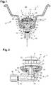
- the measurement system 1 mainly comprises a body 3 closed by a cover 5.
- the body 3 is formed from a metallic material which makes it in particular very robust and not very deformable. In the examples illustrated in figures 1 and 2 , it can be seen that the body 3 forms a part of revolution allowing a very low manufacturing cost.
- the body 3 has a recess 7 in which the members of the measurement system 1 are received and which is closed by the cover 5.
- the metallic body 3 can be, for example, formed from steel or aluminium.
- the body 3 is made of aluminum covered by a protective layer in order to prevent any corrosion of the surfaces in contact with the electrically conductive elements such as a source 15 of electrical energy or a substrate 19.
- the protective layer can be obtained, for example, by a chemical treatment such as nickel plating.
- the metallic body 3 advantageously according to the invention, serves as a receptacle and is used to guarantee the correct positioning in a blocked manner and the protection of the organs of the measurement system 1 . Indeed, in particular during the assembly and disassembly phases of a tire, the latter can come into contact with the measurement system 1 by exerting a more or less strong stress.
- the metallic body 3 therefore allows a very high resistance to deformation, in particular by shearing, which is all the higher since the body 3 is very compact, not protruding or only slightly from the groove (sometimes called "well") of the rim, which allows to keep the stable positioning of the organs between them in the system.
- the measurement system 1 mainly comprises a detection device 9, a wireless transmission device 11, a fluid non-return passage device 13, a source 15 of electrical energy and a fixing device 17 .
- the detection device 9 may comprise at least one sensor 10 powered by the electrical energy source 15 making it possible to measure the physical characteristic.
- the detection device 9 may comprise a substrate 19 such as a wafer made of polymer resin or of semiconductor material on which is formed or attached at least one integrated circuit forming the sensor 10 such as, for example, pressure and /or the temperature.
- a substrate 19 is generally protected by a product sealing, such as the silicone type, which covers it.
- the sensor 10 communicates with the internal space 22 of the pneumatic assembly 21 through an opening 6 in the cover 5.
- the wireless transmission device 11 may include an electromagnetic wave generator (not shown) powered by the source 15 of electrical energy.
- the wireless transmission device may also comprise at least one antenna 12 able to emit the electromagnetic waves generated outside the measurement system 1 .
- the electromagnetic waves are at least used to transmit values representative of the measurements obtained by the detection device 9 .
- the wireless transmission device 11 can also use the substrate 19 as described above on which is formed or attached at least one integrated circuit forming the generator (not shown) of electromagnetic waves such as, for example, radio waves. .
- the latter is, according to the invention, made of a material transparent to the electromagnetic waves of the wireless transmission device 11 such as, for example, a polymer resin or a polymer material.
- the installation of the antenna 12 at the level of the cover 5 allows emission of the electromagnetic waves as far as possible from the metallic body so that the latter does not disturb, or only slightly, the wireless transmission of the measurement system 1 .
- the values representative of the measurements obtained by the detection device 9 can be transmitted, surprisingly, by electromagnetic waves through the cover 5 without significant attenuation compared to current devices for monitoring the pressure of assemblies. passenger vehicle tires despite the proximity of the metal body 3.
- the cover 5 is substantially bowl-shaped, that is to say forms a concavity adding to the volume of the recess 7 of the body 3 in order to be able to move the antenna 12 further away from the body 3 and to more easily implant the devices 9 and 11.
- at least one pillar 37 (only one visible at the figure 1 ) and preferably three pillars 37, project, that is to say protrude, from the bottom of the concavity of the bowl shape in order to press the source 15 of electrical energy against the body 3 by passing through or next to substrate 19.
- At least a part of the antenna 12 is surrounded by the body 3 and at least another part is surrounded by the cover 5.
- the dimensions and the positionings of the body 3 and of the antenna 12 in particular with respect to each other, that is to say in particular the penetration of the antenna 12 into the body 3, make it possible to optimize the quality of the transmission of the device 11 for wireless transmission.
- the antenna 12 is preferably mounted around the devices 9 and 11 (that is to say around the electronics) of the measurement system 1 in order to provide a width and a height H 1 of the antenna 12 as high as possible, that is to say an internal area of antenna 12 as high as possible.
- the antenna 12, for example of the loop type can be connected to two opposite ends of one face of the substrate 19 and the part of the antenna 12 surrounded by the cover 5 can extend close to the cover 5 or even be in contact with the cover 5.
- the antenna 12, according to a variant explained below can, for example, be placed against a face of the cover 5 or even be embedded in the cover 5, i.e. i.e. inaccessible without breaking the cover 5.
- the part of the antenna surrounded by the body 3 thus extends, in a preferred manner, over a height H 2 less than or equal to 7 mm with respect to the plane of the substrate 19 on which the antenna 12 is electrically connected in order to to offer a sufficiently high antenna 12 internal area while keeping a very compact body 3 so as not to protrude, or only slightly, from the groove (sometimes called “well”) of the rim. Even more preferably, it has been found that a height H 2 amounting to a maximum of 3 mm for a height H 1 of at least 5 mm allows, unexpectedly, a transmission without significant attenuation compared to current devices for monitoring the pressure of passenger vehicle tire assemblies despite the proximity of the metal body 3.
- the antenna 12 is, according to a preferred variant, mounted against one face of the cover 5. More precisely, in the example illustrated in figure 1 , the antenna 12 is mounted against the internal face of the cover 5 facing the recess 7 of the body 3.
- the antenna 12 is preferably deposited against the cover 5, for example, by screen printing according to a predetermined thin pattern.
- the pattern can thus form a loop, for example annular or polygonal, or a spiral or a chicane pattern.
- the antenna 12 could be on another face of the cover 5 such as, for example, against the external face of the cover 5 facing the internal space 22 of the pneumatic assembly 21 or even embedded in cover 5, i.e. inaccessible without breaking cover 5.
- the cover 5 and the body 3 comprise at least one attachment device 25 making it possible to make them integral.
- the attachment device 25 could thus be, for example, of the screwing, push-fitting, crimping, bayonet or elastic fitting type.
- the shoulder 26 of the cover 5 is crimped by plating obtained by the deformation of at least one peripheral lip 27 of the body 3. It has been surprisingly shown that the crimped geometry of this peripheral lip 27 made of metallic material does not deteriorate the proper functioning of the wireless transmission device 11.
- the attachment device 25 completes the assembly of the measurement system 1 by allowing a geometric adaptation to the pre-assembly dispersions of the measurement system 1 in particular thanks to the deformation, preferably, of each pillar 37 of the cover 5 against the source 15 of electrical energy.
- the attachment device 25 can also allow, in the preferred variant of the antenna 12 visible at the figure 1 , to press the peripheral edge of the cover 5 comprising the shoulder 26 against the substrate 19 in order to guarantee the electrical connection of the antenna 12 to the rest of the wireless transmission device 11 present on the substrate 19 without the need for additional electrical contacts such as blades or wires.
- the latter is connected to one of the terminals of the source 15 of electrical energy by an element 16 of geometric compensation.
- the other terminal of the source 15 of electrical energy is preferably connected by contact of the substrate 19 with the shoulder 2 of the recess 7 of the body 3 in order to supply energy to the devices 9 and 11.
- the element 16 of geometric compensation can, by way of example, be a pad of polymer foam filled with electrically conductive wires or an elastomeric material filled with electrically conductive particles. It is understood that, preferably according to the invention, part of the electrical connections is made by the body 3 itself.
- the measurement system 1 thus comprises fewer components and is, consequently, more compact and more economical to manufacture.
- the body 3 can thus be electrically conductive and used as an element for transmitting electrical energy between the source 15 of electrical energy and the devices 9, 11 of the measurement system via the substrate 19 and/or the compensation 16 while allowing the wireless transmission of values representative of the measurements obtained by the detection device 9 .
- at least one electrically conductive element (track, wire, blade, etc.) could, alternatively to the electrically conductive body 3, be used as an element of transmission of electrical energy between the source 15 of electrical energy and the devices 9, 11 of the measurement system 1 via the substrate 19 and/or the compensation element 16.
- the device 13 for non-return passage of fluid is located in the lower part of the body 3.
- the device 13 essentially comprises at least one channel 14 and a non-return valve 20 allowing the inflation of the pneumatic assembly 21 and preventing its deflation. Since the valve 20 is of a conventional type for a valve assembly 21 of a vehicle tire, it will not be further described below.
- the non-return valve 20 is capped with a cap 28 for protection.
- the fixing device 17 makes it possible to attach the body 3 in a recess 24 of the rim 23 in order to make the tire assembly 21 and the measurement system 1 of the invention integral.
- the fixing device 17 may comprise at least one sealing element 18 (located between the body 3 and the rim 23 in the example of the figure 1 ) intended to guarantee the maintenance of the pressure of the internal space 22 of the tire assembly 21 .
- the fixing device 17 in the first embodiment is integral with the body 3, in extension of the body 3 and coaxially with a part of the channel 14 in order to project from the rim 23. It is therefore possible to secure the measurement system 1 on the rim 23 while allowing the tire assembly 21 to be inflated by the measurement system 1 through the channel 14.
- the fixing device 17 comprises a thread 29 on the outer surface of the body 3 and a nut 30 - washer 31 assembly in order to allow the fastening against the rim 23 of the body 3 using the nut 30 - washer 31 assembly. by screwing.
- a second embodiment illustrated in figure 2 is provided, for example, in the case where it is not desired that the device 13 of non-return passage of fluid is in straight extension of the body 3 of the system 1 of measurement.
- This implantation can be imposed, for example, when the geometry of the rim 23 imposes a bend, that is to say prevents the straight exit, on the device 13 for the non-return passage of fluid allowing the inflation of the pneumatic assembly.
- the second embodiment comprises a second body 33 attached to a body 3 similar to the first embodiment but truncated by part of its lower zone. It is also better visible figure 2 that the body 3 can include at least one shape (flats below the lip 27 like the outer surface of a nut in the case of the figure 2 ) intended to improve its prehension.
- the device 13 for non-return fluid passage is located in the second body 33.
- the device 13 essentially comprises at least a second channel 34 and a non-return valve 20 allowing the inflation of the pneumatic assembly 21 and preventing its deflation.
- the non-return valve 20 is capped with a cap 28 for protection.
- the fixing device 17 makes it possible to attach the body 3 in a recess 24 of the rim 23 in order to make the tire assembly 21 and the measurement system 1 of the invention integral.
- the fixing device 17 may comprise at least one sealing element 18 (located between the second body 33 and the rim 23 in the example of the picture 2 ) intended to guarantee the maintenance of the pressure of the internal space 22 of the tire assembly 21 .
- the rim 23 is secured between the body 3 and the second body 33 using the fixing device 17 while allowing the tire assembly 21 to be inflated by the system 1 for measuring through the channels 34 and 14.
- the fixing device 17 comprises a thread 35 on the outer surface of the body 3 and an internal thread 36 in the second body 33 in order to allow the screwing of the bodies 3, and 33 sandwiched against the rim 23.
- the second body 33 may have a geometry thus perfectly adapted to the desired location for the optimal inflation of the tire assembly 21 such as, for example, due to a rim geometry not allowing the implementation of the first embodiment of the invention. It is however understood that the body 33 may not be angled or generally oblique with respect to the body 3 as in the figure 2 but be in straight extension of the body 3 in the manner of the first embodiment as in the example illustrated in figure 1 but without being one-piece.
- the source 15 of electrical energy is mounted against the bottom 4 of the recess 7 of the body 3 so that one of the terminals (positive terminal of a button battery in the examples of figures 1 and 2 ) or preferably in direct contact with the body 3 of electrically conductive metallic material.
- a recess shown in figure 1
- the latter is always separated from the channel 14 by a wall of the body 3.
- the bottom recess 4 forms a gap at least equal to 0.1 mm and, preferably at least equal to 0.2 mm and ideally 0.5 mm, between the center of the terminal of the source 15 of electrical energy ( positive to the figure 1 ) and body 3 in order to allow the source 15 of electrical energy to expand freely under the effect of an increase in temperature.
- this prevents this expansion from deforming the substrate 19, via the compensation element 16, which would weaken the electronics of the measurement system 1 .
- this prevents this repeated expansion from progressively deforming the pillar(s) 37 of the cover 5 to the point of losing their function of maintaining and blocking the source 15 of electrical energy at the bottom 4 of body 3.
- the devices 9, 11, 13 are then mounted.
- the substrate 19 is mounted in the body 3 and the device 13 for non-return passage of fluid respectively in the body 3 and the second body 33. It is then understood that the compensation element 16 comes into contact with the other terminal (terminal negative of a button battery in the examples of figures 1 and 2 ) of the source 15 of electrical energy without the substrate 19 still resting against the shoulder 2 of the recess 7 of the body 3.
- the cover 5 is then mounted on the body 3 using the attachment device 25 passing, preferably, each pillar 37 through a hole or next to the substrate 19, in order to cap the recess 7 of the body 3 comprising the devices 9, 11 and the source 15 of electrical energy.
- the shoulder 26 of the cover 5 is crimped by plating obtained by the deformation of at least one peripheral lip 27 of the body 3.
- the attachment device 25 therefore completes the assembly of the measurement system 1 by allowing a geometric adaptation to the pre-assembly dispersions of each element of the measurement system 1.
- each free end of pillar 37 comprises a plastically and/or elastically deformable portion also making it possible to adapt the constraint of pressing the source 15 of electrical energy against the body 3 to the pre-assembly dispersions of each element of the measurement system 1.
- the attachment device 25 makes it possible to press the peripheral edge of the cover 5 against the substrate 19, to press the peripheral edge of the substrate 19 against the shoulder 2 and to deform the compensation element 16 in order to guarantee all the electrical connections of the measurement system 1 such as that of the antenna 12 and that of the source 15 of electrical energy without the need for additional electrical contacts such as blades or wires.
- the body 3 is in two parts in order to pre-assemble the cover 5 on an upper part of the body 3 and to assemble a posteriori the lower part of the body 3 already provided with the source 15 of electrical energy. and of the substrate 19 or even of the antenna 12 (for example by screwing, by bayonet fixing or by elastic fitting).
- the dimensions and/or shape of the various elements of the measurement system 1 can be modified according to the applications envisaged, such as for example another type of physical characteristic measurement than pressure or temperature and/or another type of implantation. in a pneumatic assembly 21 and/or another type of pneumatic assembly 21 such as a gas tank.
Landscapes
- Engineering & Computer Science (AREA)
- Mechanical Engineering (AREA)
- Measuring Fluid Pressure (AREA)
- Arrangements For Transmission Of Measured Signals (AREA)
Claims (11)
- System (1) zur Messung wenigstens einer physikalischen Eigenschaft für eine Reifenanordnung (21), mit einer Vorrichtung (9) zur Detektion der physikalischen Eigenschaft, einer Vorrichtung (11) zur drahtlosen Übertragung von Werten, die für die durch die Detektionsvorrichtung (9) erhaltenen Messungen repräsentativ sind, einer den Rückfluss von Fluid verhindernde Durchgangsvorrichtung (13), die das Auffüllen der Reifenanordnung (21) gestattet, und einer elektrischen Energiequelle (15), dadurch gekennzeichnet, dass das Messsystem (1) einen metallischen Körper (3) aufweist, der elektrisch leitend ist und durch einen Deckel (5) aus einem für die Wellen der drahtlosen Übertragungsvorrichtung (11) transparenten Material verschlossen ist, der dem Körper (3) gestattet, als Behältnis verwendet zu werden, das die stabile Positionierung, die Übertragung von elektrischer Energie und den mechanischen Schutz der Vorrichtungen (9, 11) des Messsystems (1) gestattet und gleichzeitig die drahtlose Übertragung von Werten, die für die durch die Detektionsvorrichtung (9) erhaltenen Messungen repräsentativ sind, durch den Deckel (5) hindurch gestattet.
- System (1) nach dem vorhergehenden Anspruch, wobei die gemessene physikalische Eigenschaft ein Druck und/oder eine Temperatur ist.
- System (1) nach einem der vorhergehenden Ansprüche, wobei die Vorrichtung (11) zur drahtlosen Übertragung einen Generator von elektromagnetischen Wellen aufweist, der durch die elektrische Energiequelle (15) gespeist wird, und wenigstens eine Antenne (12) aufweist, die imstande ist, durch den Deckel (5) hindurch die erzeugten elektromagnetischen Wellen außerhalb des Messsystems (1) zu senden.
- System (1) nach dem vorhergehenden Anspruch, wobei wenigstens ein Teil der Antenne (12) von dem Körper (3) umgeben ist und wenigstens ein anderer Teil von dem Deckel (5) umgeben ist.
- System (1) nach dem vorhergehenden Anspruch, wobei sich der Teil der Antenne (12), der von dem Körper (3) umgeben ist, auf einer Höhe (H2) erstreckt, die kleiner oder gleich 7 mm beträgt.
- System (1) nach einem der vorhergehenden Ansprüche, wobei der Körper (3) einen Boden (4) mit einer Ausnehmung aufweist, um die Ausdehnungen der elektrischen Energiequelle (15) zu kompensieren.
- System (1) nach dem vorhergehenden Anspruch, wobei die Ausnehmung einen Zwischenraum wenigstens gleich 0,1 mm zwischen der elektrischen Energiequelle (15) und dem Körper (3) bildet.
- System (1) nach einem der vorhergehenden Ansprüche, wobei der Deckel (5) wenigstens einen Pfeiler (37) aufweist, der dazu bestimmt ist, die elektrische Energiequelle (15) gegen den Körper (3) zu drücken.
- Reifenanordnung (21), aufweisend einen Luftreifen, der auf eine Felge (23) aufgepasst ist, und ein System (1) zur Messung von Druck, das auf der Felge (23) montiert ist, um wenigstens eine physikalische Eigenschaft der Reifenanordnung (21) zu überwachen, dadurch gekennzeichnet, dass das Messsystem (1) nach einem der vorhergehenden Ansprüche ausgestaltet ist.
- Reifenanordnung (21) nach dem vorhergehenden Anspruch, wobei das Messsystem (1) ferner eine Vorrichtung (17) zur Befestigung des Körpers (3) in einer Ausnehmung (24) der Felge (23) aufweist, wobei die Befestigungsvorrichtung (17) einstückig mit dem Körper (3) und in der Verlängerung des Körpers (3) ausgebildet ist, um von der Felge (23) vorzustehen, um ihre feste Verbindung auf der Felge (23) zu gestatten, und gleichzeitig das Auffüllen der Reifenanordnung (21) durch das Messsystem (1) erlaubt.
- Reifenanordnung (21) nach Anspruch 9, wobei das Messsystem (1) ferner eine Vorrichtung (17) zur Befestigung des Körpers (3) in einer Ausnehmung (24) der Felge (23) aufweist, wobei die Felge (23) zwischen dem Körper (3) und einem zweiten Körpers (33) mit Hilfe der Befestigungsvorrichtung (17) fest verbunden ist und gleichzeitig das Auffüllen der Reifenanordnung (21) durch das Messsystem (1) erlaubt.
Applications Claiming Priority (2)
| Application Number | Priority Date | Filing Date | Title |
|---|---|---|---|
| FR1901286A FR3092521B1 (fr) | 2019-02-08 | 2019-02-08 | Système de mesure d’au moins une caractéristique physique pour un ensemble pneumatique |
| PCT/EP2020/052301 WO2020160997A1 (fr) | 2019-02-08 | 2020-01-30 | Système de mesure d'au moins une caractéristique physique pour un ensemble pneumatique |
Publications (2)
| Publication Number | Publication Date |
|---|---|
| EP3921189A1 EP3921189A1 (de) | 2021-12-15 |
| EP3921189B1 true EP3921189B1 (de) | 2022-12-21 |
Family
ID=67185279
Family Applications (1)
| Application Number | Title | Priority Date | Filing Date |
|---|---|---|---|
| EP20701648.6A Active EP3921189B1 (de) | 2019-02-08 | 2020-01-30 | System zur messung mindestens einer physikalischen eigenschaft für eine reifenanordnung |
Country Status (4)
| Country | Link |
|---|---|
| US (1) | US11305594B2 (de) |
| EP (1) | EP3921189B1 (de) |
| FR (1) | FR3092521B1 (de) |
| WO (1) | WO2020160997A1 (de) |
Families Citing this family (2)
| Publication number | Priority date | Publication date | Assignee | Title |
|---|---|---|---|---|
| DE102020004720A1 (de) * | 2019-10-01 | 2021-04-01 | Helmut Schrödel | Überwachungsvorrichtung für ein Fahrzeug, Warneinrichtung für ein Fahrzeug, Warnsystem und Verfahren zum Betreiben einer Überwachungsvorrichtung |
| DE202024100187U1 (de) * | 2024-01-16 | 2025-04-22 | Canyon Bicycles Gmbh | Fahrradfelge |
Family Cites Families (6)
| Publication number | Priority date | Publication date | Assignee | Title |
|---|---|---|---|---|
| US4734674A (en) * | 1985-04-08 | 1988-03-29 | Jack Taylor | Tire pressure warning system |
| US5731516A (en) * | 1995-06-07 | 1998-03-24 | Handfield; Michael | System and method for monitoring a pneumatic tire |
| JP2004294413A (ja) * | 2003-02-12 | 2004-10-21 | Pacific Ind Co Ltd | 圧力センサ、送信機、及びタイヤ状態監視装置 |
| US7458256B1 (en) * | 2007-09-17 | 2008-12-02 | N.S. - Lin International Co., Ltd. | Tire pressure monitoring device |
| EP2208623B1 (de) * | 2009-01-08 | 2014-11-19 | Global Dynamix AG | Ventilvorrichtung, Fahrzeugreifendruckmesseinheit und Fahrzeugreifendrucksystem |
| IT1397429B1 (it) * | 2009-12-10 | 2013-01-10 | Eltek Spa | Dispositivo di monitoraggio di una ruota di un veicolo. |
-
2019
- 2019-02-08 FR FR1901286A patent/FR3092521B1/fr active Active
-
2020
- 2020-01-30 EP EP20701648.6A patent/EP3921189B1/de active Active
- 2020-01-30 WO PCT/EP2020/052301 patent/WO2020160997A1/fr not_active Ceased
- 2020-01-30 US US17/310,479 patent/US11305594B2/en active Active
Also Published As
| Publication number | Publication date |
|---|---|
| FR3092521A1 (fr) | 2020-08-14 |
| US20220041020A1 (en) | 2022-02-10 |
| WO2020160997A1 (fr) | 2020-08-13 |
| US11305594B2 (en) | 2022-04-19 |
| EP3921189A1 (de) | 2021-12-15 |
| FR3092521B1 (fr) | 2021-09-03 |
Similar Documents
| Publication | Publication Date | Title |
|---|---|---|
| FR2907048A1 (fr) | Unite electronique de mesure de parametres de fonctionnement d'une roue de vehicule. | |
| EP2385905A1 (de) | Lager und einsatz zur befestigung eines moduls an einer reifenwand | |
| EP3247574B1 (de) | Reifenartige vorrichtung für ein fahrzeug | |
| FR3066438A1 (fr) | Valve de gonflage pour pneu amelioree | |
| FR2839470A1 (fr) | Dispositif de fixation d'un capteur de pression destine a etre monte dans un pneumatique | |
| WO2020160997A1 (fr) | Système de mesure d'au moins une caractéristique physique pour un ensemble pneumatique | |
| FR3048156B1 (fr) | Boitier de module electronique et unite electronique de mesure de parametres de fonctionnement d'une roue de vehicule | |
| FR3058360A1 (fr) | Unite electronique de mesure de parametres de fonctionnement d'une roue de vehicule | |
| FR2978378A1 (fr) | Unite electronique de mesure de parametres de fonctionnement d'une roue de vehicule, comprenant un boitier electronique et une valve de gonflage | |
| EP1106388B1 (de) | Nutzfahrzeugrad mit einem aussen an der Radscheibe mündenden Ventil | |
| EP4127638A1 (de) | Reifendruckmessvorrichtung | |
| FR2940770A1 (fr) | Dispositif de roulage a plat pour vehicule automobile et ensemble monte l'incorporant | |
| EP2595845B1 (de) | Verfahren und vorrichtung zum reifendruck-kontrolle und -regelung in montierten reifen. | |
| WO2019155170A1 (fr) | Unité électronique de mesure de paramètres de fonctionnement d'une roue de véhicule, comprenant un boîtier électronique et une valve de gonflage de type à déformation élastique | |
| EP1354728B1 (de) | Gelenkvorrichtung von einem Reifendrucksensor auf einer Felge eines Fahrzeugs | |
| WO2015032466A1 (fr) | Jante munie d'une valve de gonflage et procede de montage d'une telle valve | |
| EP1338445A1 (de) | Vorrichtung zur Befestigung von einem Modul eines Reifenüberwachungssystem auf ein Rad | |
| FR2845031A1 (fr) | Dispositif de fixation pour boitier de capteur de pression des pneus et procede correspondant | |
| EP3490813A1 (de) | Reifenartige vorrichtung für ein fahrzeug | |
| EP3727882A1 (de) | Reifenelement | |
| FR2844480A1 (fr) | Roue de vehicule | |
| FR3077385A1 (fr) | Unite electronique de mesure de parametres de fonctionnement d'une roue de vehicule adaptee pour etre positionnee sur la face interne d'une bande de roulement d'un pneumatique | |
| WO2009066043A1 (fr) | Structure de vehicule automobile | |
| FR2908349A1 (fr) | Element de fixation pour valve de pneumatique | |
| FR3075100A1 (fr) | Ensemble monte pour vehicule avec un systeme de surveillance de caracteristique d'un bandage pneumatique ferme |
Legal Events
| Date | Code | Title | Description |
|---|---|---|---|
| STAA | Information on the status of an ep patent application or granted ep patent |
Free format text: STATUS: UNKNOWN |
|
| STAA | Information on the status of an ep patent application or granted ep patent |
Free format text: STATUS: THE INTERNATIONAL PUBLICATION HAS BEEN MADE |
|
| PUAI | Public reference made under article 153(3) epc to a published international application that has entered the european phase |
Free format text: ORIGINAL CODE: 0009012 |
|
| STAA | Information on the status of an ep patent application or granted ep patent |
Free format text: STATUS: REQUEST FOR EXAMINATION WAS MADE |
|
| 17P | Request for examination filed |
Effective date: 20210716 |
|
| AK | Designated contracting states |
Kind code of ref document: A1 Designated state(s): AL AT BE BG CH CY CZ DE DK EE ES FI FR GB GR HR HU IE IS IT LI LT LU LV MC MK MT NL NO PL PT RO RS SE SI SK SM TR |
|
| DAX | Request for extension of the european patent (deleted) | ||
| RAV | Requested validation state of the european patent: fee paid |
Extension state: MA Effective date: 20210716 Extension state: KH Effective date: 20210716 |
|
| GRAP | Despatch of communication of intention to grant a patent |
Free format text: ORIGINAL CODE: EPIDOSNIGR1 |
|
| STAA | Information on the status of an ep patent application or granted ep patent |
Free format text: STATUS: GRANT OF PATENT IS INTENDED |
|
| INTG | Intention to grant announced |
Effective date: 20220926 |
|
| GRAS | Grant fee paid |
Free format text: ORIGINAL CODE: EPIDOSNIGR3 |
|
| GRAA | (expected) grant |
Free format text: ORIGINAL CODE: 0009210 |
|
| STAA | Information on the status of an ep patent application or granted ep patent |
Free format text: STATUS: THE PATENT HAS BEEN GRANTED |
|
| AK | Designated contracting states |
Kind code of ref document: B1 Designated state(s): AL AT BE BG CH CY CZ DE DK EE ES FI FR GB GR HR HU IE IS IT LI LT LU LV MC MK MT NL NO PL PT RO RS SE SI SK SM TR |
|
| REG | Reference to a national code |
Ref country code: GB Ref legal event code: FG4D Free format text: NOT ENGLISH |
|
| REG | Reference to a national code |
Ref country code: DE Ref legal event code: R096 Ref document number: 602020007072 Country of ref document: DE |
|
| REG | Reference to a national code |
Ref country code: CH Ref legal event code: EP |
|
| REG | Reference to a national code |
Ref country code: AT Ref legal event code: REF Ref document number: 1538846 Country of ref document: AT Kind code of ref document: T Effective date: 20230115 |
|
| REG | Reference to a national code |
Ref country code: IE Ref legal event code: FG4D Free format text: LANGUAGE OF EP DOCUMENT: FRENCH |
|
| REG | Reference to a national code |
Ref country code: LT Ref legal event code: MG9D |
|
| REG | Reference to a national code |
Ref country code: NL Ref legal event code: MP Effective date: 20221221 |
|
| PG25 | Lapsed in a contracting state [announced via postgrant information from national office to epo] |
Ref country code: SE Free format text: LAPSE BECAUSE OF FAILURE TO SUBMIT A TRANSLATION OF THE DESCRIPTION OR TO PAY THE FEE WITHIN THE PRESCRIBED TIME-LIMIT Effective date: 20221221 Ref country code: NO Free format text: LAPSE BECAUSE OF FAILURE TO SUBMIT A TRANSLATION OF THE DESCRIPTION OR TO PAY THE FEE WITHIN THE PRESCRIBED TIME-LIMIT Effective date: 20230321 Ref country code: LT Free format text: LAPSE BECAUSE OF FAILURE TO SUBMIT A TRANSLATION OF THE DESCRIPTION OR TO PAY THE FEE WITHIN THE PRESCRIBED TIME-LIMIT Effective date: 20221221 Ref country code: FI Free format text: LAPSE BECAUSE OF FAILURE TO SUBMIT A TRANSLATION OF THE DESCRIPTION OR TO PAY THE FEE WITHIN THE PRESCRIBED TIME-LIMIT Effective date: 20221221 |
|
| REG | Reference to a national code |
Ref country code: AT Ref legal event code: MK05 Ref document number: 1538846 Country of ref document: AT Kind code of ref document: T Effective date: 20221221 |
|
| PG25 | Lapsed in a contracting state [announced via postgrant information from national office to epo] |
Ref country code: RS Free format text: LAPSE BECAUSE OF FAILURE TO SUBMIT A TRANSLATION OF THE DESCRIPTION OR TO PAY THE FEE WITHIN THE PRESCRIBED TIME-LIMIT Effective date: 20221221 Ref country code: LV Free format text: LAPSE BECAUSE OF FAILURE TO SUBMIT A TRANSLATION OF THE DESCRIPTION OR TO PAY THE FEE WITHIN THE PRESCRIBED TIME-LIMIT Effective date: 20221221 Ref country code: HR Free format text: LAPSE BECAUSE OF FAILURE TO SUBMIT A TRANSLATION OF THE DESCRIPTION OR TO PAY THE FEE WITHIN THE PRESCRIBED TIME-LIMIT Effective date: 20221221 Ref country code: GR Free format text: LAPSE BECAUSE OF FAILURE TO SUBMIT A TRANSLATION OF THE DESCRIPTION OR TO PAY THE FEE WITHIN THE PRESCRIBED TIME-LIMIT Effective date: 20230322 |
|
| PG25 | Lapsed in a contracting state [announced via postgrant information from national office to epo] |
Ref country code: NL Free format text: LAPSE BECAUSE OF FAILURE TO SUBMIT A TRANSLATION OF THE DESCRIPTION OR TO PAY THE FEE WITHIN THE PRESCRIBED TIME-LIMIT Effective date: 20221221 |
|
| PG25 | Lapsed in a contracting state [announced via postgrant information from national office to epo] |
Ref country code: SM Free format text: LAPSE BECAUSE OF FAILURE TO SUBMIT A TRANSLATION OF THE DESCRIPTION OR TO PAY THE FEE WITHIN THE PRESCRIBED TIME-LIMIT Effective date: 20221221 Ref country code: RO Free format text: LAPSE BECAUSE OF FAILURE TO SUBMIT A TRANSLATION OF THE DESCRIPTION OR TO PAY THE FEE WITHIN THE PRESCRIBED TIME-LIMIT Effective date: 20221221 Ref country code: PT Free format text: LAPSE BECAUSE OF FAILURE TO SUBMIT A TRANSLATION OF THE DESCRIPTION OR TO PAY THE FEE WITHIN THE PRESCRIBED TIME-LIMIT Effective date: 20230421 Ref country code: ES Free format text: LAPSE BECAUSE OF FAILURE TO SUBMIT A TRANSLATION OF THE DESCRIPTION OR TO PAY THE FEE WITHIN THE PRESCRIBED TIME-LIMIT Effective date: 20221221 Ref country code: EE Free format text: LAPSE BECAUSE OF FAILURE TO SUBMIT A TRANSLATION OF THE DESCRIPTION OR TO PAY THE FEE WITHIN THE PRESCRIBED TIME-LIMIT Effective date: 20221221 Ref country code: CZ Free format text: LAPSE BECAUSE OF FAILURE TO SUBMIT A TRANSLATION OF THE DESCRIPTION OR TO PAY THE FEE WITHIN THE PRESCRIBED TIME-LIMIT Effective date: 20221221 Ref country code: AT Free format text: LAPSE BECAUSE OF FAILURE TO SUBMIT A TRANSLATION OF THE DESCRIPTION OR TO PAY THE FEE WITHIN THE PRESCRIBED TIME-LIMIT Effective date: 20221221 |
|
| PG25 | Lapsed in a contracting state [announced via postgrant information from national office to epo] |
Ref country code: SK Free format text: LAPSE BECAUSE OF FAILURE TO SUBMIT A TRANSLATION OF THE DESCRIPTION OR TO PAY THE FEE WITHIN THE PRESCRIBED TIME-LIMIT Effective date: 20221221 Ref country code: PL Free format text: LAPSE BECAUSE OF FAILURE TO SUBMIT A TRANSLATION OF THE DESCRIPTION OR TO PAY THE FEE WITHIN THE PRESCRIBED TIME-LIMIT Effective date: 20221221 Ref country code: IS Free format text: LAPSE BECAUSE OF FAILURE TO SUBMIT A TRANSLATION OF THE DESCRIPTION OR TO PAY THE FEE WITHIN THE PRESCRIBED TIME-LIMIT Effective date: 20230421 Ref country code: AL Free format text: LAPSE BECAUSE OF FAILURE TO SUBMIT A TRANSLATION OF THE DESCRIPTION OR TO PAY THE FEE WITHIN THE PRESCRIBED TIME-LIMIT Effective date: 20221221 |
|
| REG | Reference to a national code |
Ref country code: CH Ref legal event code: PL |
|
| REG | Reference to a national code |
Ref country code: DE Ref legal event code: R097 Ref document number: 602020007072 Country of ref document: DE |
|
| PG25 | Lapsed in a contracting state [announced via postgrant information from national office to epo] |
Ref country code: MC Free format text: LAPSE BECAUSE OF FAILURE TO SUBMIT A TRANSLATION OF THE DESCRIPTION OR TO PAY THE FEE WITHIN THE PRESCRIBED TIME-LIMIT Effective date: 20221221 Ref country code: LU Free format text: LAPSE BECAUSE OF NON-PAYMENT OF DUE FEES Effective date: 20230130 |
|
| REG | Reference to a national code |
Ref country code: BE Ref legal event code: MM Effective date: 20230131 |
|
| PLBE | No opposition filed within time limit |
Free format text: ORIGINAL CODE: 0009261 |
|
| STAA | Information on the status of an ep patent application or granted ep patent |
Free format text: STATUS: NO OPPOSITION FILED WITHIN TIME LIMIT |
|
| PG25 | Lapsed in a contracting state [announced via postgrant information from national office to epo] |
Ref country code: LI Free format text: LAPSE BECAUSE OF NON-PAYMENT OF DUE FEES Effective date: 20230131 Ref country code: DK Free format text: LAPSE BECAUSE OF FAILURE TO SUBMIT A TRANSLATION OF THE DESCRIPTION OR TO PAY THE FEE WITHIN THE PRESCRIBED TIME-LIMIT Effective date: 20221221 Ref country code: CH Free format text: LAPSE BECAUSE OF NON-PAYMENT OF DUE FEES Effective date: 20230131 |
|
| 26N | No opposition filed |
Effective date: 20230922 |
|
| PG25 | Lapsed in a contracting state [announced via postgrant information from national office to epo] |
Ref country code: BE Free format text: LAPSE BECAUSE OF NON-PAYMENT OF DUE FEES Effective date: 20230131 |
|
| PG25 | Lapsed in a contracting state [announced via postgrant information from national office to epo] |
Ref country code: SI Free format text: LAPSE BECAUSE OF FAILURE TO SUBMIT A TRANSLATION OF THE DESCRIPTION OR TO PAY THE FEE WITHIN THE PRESCRIBED TIME-LIMIT Effective date: 20221221 Ref country code: IE Free format text: LAPSE BECAUSE OF NON-PAYMENT OF DUE FEES Effective date: 20230130 |
|
| PG25 | Lapsed in a contracting state [announced via postgrant information from national office to epo] |
Ref country code: BG Free format text: LAPSE BECAUSE OF FAILURE TO SUBMIT A TRANSLATION OF THE DESCRIPTION OR TO PAY THE FEE WITHIN THE PRESCRIBED TIME-LIMIT Effective date: 20221221 |
|
| PG25 | Lapsed in a contracting state [announced via postgrant information from national office to epo] |
Ref country code: BG Free format text: LAPSE BECAUSE OF FAILURE TO SUBMIT A TRANSLATION OF THE DESCRIPTION OR TO PAY THE FEE WITHIN THE PRESCRIBED TIME-LIMIT Effective date: 20221221 |
|
| PG25 | Lapsed in a contracting state [announced via postgrant information from national office to epo] |
Ref country code: CY Free format text: LAPSE BECAUSE OF FAILURE TO SUBMIT A TRANSLATION OF THE DESCRIPTION OR TO PAY THE FEE WITHIN THE PRESCRIBED TIME-LIMIT; INVALID AB INITIO Effective date: 20200130 |
|
| PG25 | Lapsed in a contracting state [announced via postgrant information from national office to epo] |
Ref country code: HU Free format text: LAPSE BECAUSE OF FAILURE TO SUBMIT A TRANSLATION OF THE DESCRIPTION OR TO PAY THE FEE WITHIN THE PRESCRIBED TIME-LIMIT; INVALID AB INITIO Effective date: 20200130 |
|
| VS25 | Lapsed in a validation state [announced via postgrant information from nat. office to epo] |
Ref country code: MA Free format text: FAILURE TO ELECT DOMICILE IN THE NATIONAL COUNTRY Effective date: 20230322 |
|
| PG25 | Lapsed in a contracting state [announced via postgrant information from national office to epo] |
Ref country code: TR Free format text: LAPSE BECAUSE OF FAILURE TO SUBMIT A TRANSLATION OF THE DESCRIPTION OR TO PAY THE FEE WITHIN THE PRESCRIBED TIME-LIMIT Effective date: 20221221 |
|
| VS25 | Lapsed in a validation state [announced via postgrant information from nat. office to epo] |
Ref country code: MA Free format text: LAPSE BECAUSE OF FAILURE TO SUBMIT A TRANSLATION OF THE DESCRIPTION OR TO PAY THE FEE WITHIN THE PRESCRIBED TIME-LIMIT Effective date: 20221221 |
|
| PGFP | Annual fee paid to national office [announced via postgrant information from national office to epo] |
Ref country code: GB Payment date: 20260123 Year of fee payment: 7 |
|
| PGFP | Annual fee paid to national office [announced via postgrant information from national office to epo] |
Ref country code: DE Payment date: 20260121 Year of fee payment: 7 |
|
| PGFP | Annual fee paid to national office [announced via postgrant information from national office to epo] |
Ref country code: IT Payment date: 20260126 Year of fee payment: 7 |
|
| PGFP | Annual fee paid to national office [announced via postgrant information from national office to epo] |
Ref country code: FR Payment date: 20260129 Year of fee payment: 7 |