EP3920575B1 - Energiesparsignaldetektionsverfahren, ressourcenbestimmungsverfahren und zugehörige vorrichtung - Google Patents
Energiesparsignaldetektionsverfahren, ressourcenbestimmungsverfahren und zugehörige vorrichtung Download PDFInfo
- Publication number
- EP3920575B1 EP3920575B1 EP20749248.9A EP20749248A EP3920575B1 EP 3920575 B1 EP3920575 B1 EP 3920575B1 EP 20749248 A EP20749248 A EP 20749248A EP 3920575 B1 EP3920575 B1 EP 3920575B1
- Authority
- EP
- European Patent Office
- Prior art keywords
- signal
- power
- time interval
- saving signal
- saving
- Prior art date
- Legal status (The legal status is an assumption and is not a legal conclusion. Google has not performed a legal analysis and makes no representation as to the accuracy of the status listed.)
- Active
Links
Images


Classifications
-
- H—ELECTRICITY
- H04—ELECTRIC COMMUNICATION TECHNIQUE
- H04W—WIRELESS COMMUNICATION NETWORKS
- H04W24/00—Supervisory, monitoring or testing arrangements
- H04W24/02—Arrangements for optimising operational condition
-
- H—ELECTRICITY
- H04—ELECTRIC COMMUNICATION TECHNIQUE
- H04W—WIRELESS COMMUNICATION NETWORKS
- H04W72/00—Local resource management
- H04W72/04—Wireless resource allocation
- H04W72/044—Wireless resource allocation based on the type of the allocated resource
- H04W72/0446—Resources in time domain, e.g. slots or frames
-
- H—ELECTRICITY
- H04—ELECTRIC COMMUNICATION TECHNIQUE
- H04W—WIRELESS COMMUNICATION NETWORKS
- H04W24/00—Supervisory, monitoring or testing arrangements
- H04W24/08—Testing, supervising or monitoring using real traffic
-
- H—ELECTRICITY
- H04—ELECTRIC COMMUNICATION TECHNIQUE
- H04W—WIRELESS COMMUNICATION NETWORKS
- H04W52/00—Power management, e.g. Transmission Power Control [TPC] or power classes
- H04W52/02—Power saving arrangements
- H04W52/0209—Power saving arrangements in terminal devices
- H04W52/0212—Power saving arrangements in terminal devices managed by the network, e.g. network or access point is leader and terminal is follower
- H04W52/0216—Power saving arrangements in terminal devices managed by the network, e.g. network or access point is leader and terminal is follower using a pre-established activity schedule, e.g. traffic indication frame
-
- H—ELECTRICITY
- H04—ELECTRIC COMMUNICATION TECHNIQUE
- H04W—WIRELESS COMMUNICATION NETWORKS
- H04W52/00—Power management, e.g. Transmission Power Control [TPC] or power classes
- H04W52/02—Power saving arrangements
- H04W52/0209—Power saving arrangements in terminal devices
- H04W52/0225—Power saving arrangements in terminal devices using monitoring of external events, e.g. the presence of a signal
- H04W52/0229—Power saving arrangements in terminal devices using monitoring of external events, e.g. the presence of a signal where the received signal is a wanted signal
- H04W52/0235—Power saving arrangements in terminal devices using monitoring of external events, e.g. the presence of a signal where the received signal is a wanted signal where the received signal is a power saving command
-
- H—ELECTRICITY
- H04—ELECTRIC COMMUNICATION TECHNIQUE
- H04W—WIRELESS COMMUNICATION NETWORKS
- H04W52/00—Power management, e.g. Transmission Power Control [TPC] or power classes
- H04W52/02—Power saving arrangements
- H04W52/0209—Power saving arrangements in terminal devices
- H04W52/0225—Power saving arrangements in terminal devices using monitoring of external events, e.g. the presence of a signal
- H04W52/0245—Power saving arrangements in terminal devices using monitoring of external events, e.g. the presence of a signal according to signal strength
-
- H—ELECTRICITY
- H04—ELECTRIC COMMUNICATION TECHNIQUE
- H04W—WIRELESS COMMUNICATION NETWORKS
- H04W52/00—Power management, e.g. Transmission Power Control [TPC] or power classes
- H04W52/02—Power saving arrangements
- H04W52/0209—Power saving arrangements in terminal devices
- H04W52/0261—Power saving arrangements in terminal devices managing power supply demand, e.g. depending on battery level
- H04W52/0274—Power saving arrangements in terminal devices managing power supply demand, e.g. depending on battery level by switching on or off the equipment or parts thereof
- H04W52/028—Power saving arrangements in terminal devices managing power supply demand, e.g. depending on battery level by switching on or off the equipment or parts thereof switching on or off only a part of the equipment circuit blocks
-
- H—ELECTRICITY
- H04—ELECTRIC COMMUNICATION TECHNIQUE
- H04W—WIRELESS COMMUNICATION NETWORKS
- H04W76/00—Connection management
- H04W76/20—Manipulation of established connections
- H04W76/28—Discontinuous transmission [DTX]; Discontinuous reception [DRX]
-
- Y—GENERAL TAGGING OF NEW TECHNOLOGICAL DEVELOPMENTS; GENERAL TAGGING OF CROSS-SECTIONAL TECHNOLOGIES SPANNING OVER SEVERAL SECTIONS OF THE IPC; TECHNICAL SUBJECTS COVERED BY FORMER USPC CROSS-REFERENCE ART COLLECTIONS [XRACs] AND DIGESTS
- Y02—TECHNOLOGIES OR APPLICATIONS FOR MITIGATION OR ADAPTATION AGAINST CLIMATE CHANGE
- Y02D—CLIMATE CHANGE MITIGATION TECHNOLOGIES IN INFORMATION AND COMMUNICATION TECHNOLOGIES [ICT], I.E. INFORMATION AND COMMUNICATION TECHNOLOGIES AIMING AT THE REDUCTION OF THEIR OWN ENERGY USE
- Y02D30/00—Reducing energy consumption in communication networks
- Y02D30/70—Reducing energy consumption in communication networks in wireless communication networks
Definitions
- the present disclosure relates to the field of communications technologies, and in particular, to a power-saving signal detecting method, a resource determining method and related devices.
- a discontinuous reception (Discontinuous Reception, DRX) mechanism is proposed, where the foregoing DRX may include DRX in a radio resource control (Radio Resource Control, RRC)-idle (that is, RRC_IDLE) state or in an RRC-inactive (that is, RRC_INACTIVE) state and DRX in an RRC-connected (that is, RRC_CONNECTED) state.
- RRC Radio Resource Control
- the concept of power-saving signal is further proposed. Specifically, if a power-saving signal instructs UE to detect a PDCCH at the time of a paging occasion (Paging Occasion, PO) or a PDCCH during onduration (that is, OnDuration) in a DRX cycle, the UE detects the PDCCH; and if the power-saving signal skips instructing the UE to detect a PDCCH at the time of a PO or a PDCCH during OnDuration in a DRX cycle, the UE skips detecting the PDCCH.
- a power-saving signal instructs UE to detect a PDCCH at the time of a paging occasion (Paging Occasion, PO) or a PDCCH during onduration (that is, OnDuration) in a DRX cycle
- the UE detects the PDCCH
- D1 discloses that the power saving signal should be supported in RRC_CONNECTED and RRC_IDLE modes, and power saving signal should be used to trigger on-demand RS transmission for assisting UE in performing channel tracking and CSI measurement, and power saving signal transmitted in current DRX ON can be used, 'for indication of UEs power consumption reduction of upcoming DRX ON cycles, and power saving signal could be used for triggering UE skipping PDCCH monitoring on DRX ON period, and The following should be considered for tile power saving signal design: receiver complexity and sensitive for the energy detection, flexibility and system overhead, power consumption of tile power saving signal detection, and signal based power saving signal could be supported for triggering the receiver from wakeup to sleep, and if DCI based power signal could be supported, it should be transmitted in DRX ON period.
- D2 discloses that the power saving scheme based on the power saving signal trigger UE adaptation to the BWP, and the power saving schemes with cross-slot scheduling with known K0 to the UE in advance provides power saving gain up to 17%, and dynamic signaling, such as DCI, to indicate the number of Tx/Rx antenna should be studied for the power saving scheme with antenna adaptation, and Significant power saving gain up to 79% can be achieved by the power saving signal triggered UE adaptation to the DRX operation, the power saving signal as the triggering indication for the adaptation of UE wakeup at each DRX ON cycle should be supported, and the power saving signal as the indication of the PDCCH decoding would reduce PDCCH monitoring occasion and thus UE power consumption reduction, and the on-demand PS-RS could be configured before PDCCH monitoring for UE to acquire up-to-date channel information for the channel compensation of PDCCH decoding when the power saving signal is used for triggering PDCCH decoding, and significant power saving gain up to 35% can be achieved by the power saving signal
- D3 discloses that the power saving signal/channel for UE adaptation includes the following signals/channels for further study: Existing signal/channel based power saving signal/channel and New power saving signal/channel-sequence based, and the power saving signal/channel in trigger UE adaptation to DRX operation for further study is that the power saving signal/channel can be configured along the DRX configuration as the indication for UE to wake up from the sleep state.
- RS resources can be considered to assist UE in performing RRM/CSI measurement and channel time/frequency and/or beam tracking.
- D4 discloses that for some concern conditions, the number of RSRP measurement samples for a measurement period can be relaxed with negligible impact on accuracy, and for some concern conditions, increasing measurement period can be efficient for UE power saving, and for some concern conditions, reducing the number of cells for intra-frequency measurement can cause significant for UE power saving, and on-demand RS based RRM measurement can be beneficial for UE power saving, in which UE would finish measurement during DRX-ON period and go to sleep after all, and the on-demand RS assistant RRM measurement during data transmission can obtain partial power saving gain.
- the embodiments of the present disclosure provide a power-saving signal detecting method, a resource determining method and related devices, to provide a way of applying a power-saving signal.
- an embodiment of the present disclosure provides a power-saving signal detecting method, where the method is applied to a terminal device, which is defined in claim 1.
- an embodiment of the present disclosure further provides a power-saving signal detecting method, where the method is applied to a network side device, which is defined in claim 4.
- an embodiment of the present disclosure provides a resource determining method, where the method is applied to a terminal device, which is defined in claim 8.
- an embodiment of the present disclosure provides a resource determining method, where the method is applied to a network side device, which is defined in claim 11.
- a way of detecting a power-saving signal is standardized, which can not only reduce power consumption of a terminal device, but also improve the communication reliability.
- new radio supports a power-saving parameter related to user equipment (UE) (or referred to a terminal device), such as a size of a bandwidth part (Bandwidth Part, BWP), a number of multiple-input multiple-output (Multiple-Input Multiple-Output, MIMO) layers, and a number of downlink component carriers activated at the same time.
- UE user equipment
- BWP Bandwidth Part
- MIMO Multiple-Input Multiple-Output
- Different values of the foregoing power-saving parameter may lead to different power consumption of a terminal device.
- UE in an RRC_IDLE state periodically detects a paging signal, and the probability of receiving a paging signal belonging to the UE is relatively low.
- power consumption of detecting a PDCCH and a PDSCH each time is great, it is not conducive to power-saving for a terminal.
- a basic mechanism of DRX is to configure one DRX cycle (that is, DRX Cycle) for UE in a RRC _CONNECTED state.
- a DRX cycle consists of an on duration (that is, OnDuration) and an opportunity for DRX (that is, Opportunity for DRX), where during the on duration, UE monitors and receives a PDCCH (that is, an active period); during the opportunity for DRX(that is, Opportunity for DRX), UE skips receiving data of any downlink channel to reduce power consumption (that is, sleep period).
- a DRX start offset (that is, drxStartOffset) specifies a start subframe of a DRX cycle
- a long DRX-Cycle (that is, longDRX-Cycle) specifies how many subframes a long DRX cycle (that is, long DRX Cycle) occupies.
- An on duration timer (that is, OnDurationTimer) specifies a number of a PDCCH's consecutive subframes (that is, a number of subframes during which an active period lasts) that need to be monitored starting from a start subframe of a DRX cycle.
- a DRX inactivity timer that is, drx-InactivityTimer
- the DRX inactivity timer indicates a number of consecutive subframes that are continuously in an active state after the UE successfully decodes new uplink (Uplink, UL) or downlink (Downlink, DL) data scheduled by one PDCCH. That is, the DRX inactivity timer is restarted every time when transmitted new data is scheduled for the UE.
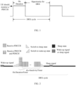
- a wake-up signal (Wake-Up Signal, WUS) and a sleep signal are proposed, where the foregoing wake-up signal and sleep signal may be collectively referred to as power-saving signals (that is, Power Saving Signal).
- a base station may transmit one power-saving signal to UE before a paging occasion (Paging Occasion, PO), and the UE detects the power-saving signal at the corresponding time.
- Paging Occasion, PO paging occasion
- the UE detects the PDCCH; if the power-saving signal skips instructing the UE to detect a PDCCH at the PO time, the UE skips detecting the PDCCH.
- detecting a wake-up signal is less complicated and more power-saving than blindly detecting a paging (that is, Paging) signal or a PDCCH.
- a base station transmits one power-saving signal to UE before OnDuration or at the beginning of OnDuration, and the UE detects the power-saving signal at the corresponding time.
- the UE detects the PDCCH; if the power-saving signal skips instructing the UE to detect the PDCCH of OnDuration, the UE skips detecting the PDCCH.
- detecting a wake-up signal is less complicated and more power-saving than blindly detecting a paging (that is, Paging) signal or a PDCCH.
- the foregoing power-saving signal may be a signal transmitted on a PDCCH, or a sequence-based signal, such as a channel state information reference signal (Channel State Information Reference Signal, CSI-RS), or an on-off keying (On-Off Keying, OOK) signal.
- CSI-RS Channel State Information Reference Signal
- OOK On-Off Keying
- FIG. 3 is a structural diagram of a network system applicable to the embodiments of the present disclosure.
- the network system includes a terminal device 11 and a network side device 12.
- the terminal device 11 may be a user side device such as a mobile phone, a tablet personal computer (Tablet Personal Computer), a laptop computer (Laptop Computer), a personal digital assistant (Personal Digital Assistant, PDA), a mobile Internet device (Mobile Internet Device, MID), or a wearable device (Wearable Device). It should be noted that a specific type of the terminal device 11 is not limited in the embodiments of the present disclosure.
- the network side device 12 may be a base station, for example, a macro base station, an LTE evolved NodeB (evolutional Node B, eNB), a 5G NR NodeB (NodeB, NB), or a next generation Node B (next generation Node B, gNB).
- the network side device 12 may be alternatively a small cell, for example, a low power node (Low Power Node, LPN), a picocell base station (pico) or a femto base station (femto), or the network side device 12 may be an access point (Access Point, AP).
- LPN Low Power Node
- pico picocell base station
- femto femto
- the base station may be alternatively a network node formed by a central unit (Central Unit, CU) and a plurality of transmission reception points (transmission reception point, TRP) that are managed and controlled by the CU.
- Central Unit Central Unit
- TRP transmission reception point
- the terminal device 11 may determine whether to detect a power-saving signal according to a measured measurement quantity related to a channel condition, where the foregoing measured measurement quantity related to a channel condition may include, but are not limited to, at least one of the following: a reference signal received power (Reference Signal Received Power, RSRP), an measurement quantity related to a change of RSRP, reference signal received quality (Reference Signal Received Quality, RSRQ), an measurement quantity related to a change of RSRQ, a signal to interference plus noise ratio (Signal-to-Noise and Interference Ratio, SINR), an measurement quantity related to a change of SINR, a mobility (that is, Mobility) parameter.
- RSRP Reference Signal Received Power
- RSRQ Reference Signal Received Quality
- SINR Signal to interference plus noise ratio
- SINR Signal-to-Noise and Interference Ratio
- measurement quantity related to a change of RSRP may all be set properly according to an actual need.
- the foregoing measurement quantity related to a change of RSRP may be a variance or a standard deviation of RSRP obtained by means of multiple measurements, for example, a variance or a standard deviation of all RSRP measured during a period of time; a difference between or a ratio of a value of RSRP measured currently to a value of RSRP measured previously, or the like.
- the foregoing measurement quantity related to a change of RSRQ may be a variance or a standard deviation of RSRQ obtained by means of multiple measurements, for example, a variance or a standard deviation of all RSRQ measured during a period of time; a difference between or a ratio of a value of RSRQ measured currently to a value of RSRQ measured previously, or the like.
- the foregoing measurement quantity related to a change of SINR may be a variance or a standard deviation of SINRs obtained by means of multiple measurements, for example, a variance or a standard deviation of all SINRs measured during a period of time; a difference between or a ratio of a value of SINR measured currently to a value of SINR measured previously, or the like.
- the foregoing measurement quantity related to mobility may be an indicator used to measure mobility of the terminal device 11, for example, it may be a number of cells on which the terminal device 11 camps within a first preset time, a number of beams on which the terminal device camps within a second preset time, a movement velocity of the terminal device 11, a Doppler frequency shift of the terminal device, or a number of transmission configuration indicator (Transmission Configuration Indicator, TCI) states (that is, State) of the terminal device 11 within a third preset time.
- TCI Transmission Configuration Indicator
- the foregoing first preset time, second preset time, and third preset time may all be set properly according to an actual need, which is not limited in this embodiment.
- the foregoing power-saving signal may be a signal transmitted on a PDCCH; it may also be a sequence-based signal, where the sequence-based signal may be a CSI-RS, a primary synchronization signal (Primary Synchronisation Signal, PSS), and a secondary synchronization signal (Secondary Synchronisation Signal, SSS), a tracking reference signal (Tracking Reference Signal, TRS) or a demodulation reference signal (Demodulation Reference Signal, DMRS), or the like.
- CSI-RS CSI-RS
- PSS Primary Synchronisation Signal
- SSS secondary synchronization signal
- SSS Track Reference Signal
- TRS Track Reference Signal
- DMRS demodulation Reference Signal
- the terminal device 11 may detect the power-saving signal in the case that the measured measurement quantity related to a channel condition satisfies a threshold requirement; skip requiring detecting the power-saving signal in the case that the measured measurement quantity related to a channel condition fails to satisfy a threshold, and at this time, a PDCCH associated with the power-saving signal may be detected.
- the foregoing skipping requiring detecting the power-saving signal may mean that the terminal device may detect the power-saving signal, or may not detect the power-saving signal.
- the foregoing PDCCH associated with the power-saving signal may include a PDCCH carrying paging information, or a PDCCH located at OnDuration in a DRX cycle.
- the foregoing PDCCH associated with the power-saving signal may be a PDCCH carrying paging information
- RRC_CONNECTED state the foregoing PDCCH associated with the power-saving signal may be a PDCCH located at OnDuration in a DRX cycle.
- the foregoing threshold corresponds to the measurement quantity related to a channel condition.
- the foregoing threshold may include a threshold for the RSRP; if the foregoing measurement quantity related to a channel condition includes RSRQ, the foregoing threshold may include a threshold for the RSRQ; if the foregoing measurement quantity related to a channel condition includes RSRP and RSRQ, the foregoing threshold may include a threshold for the RSRP and a threshold for the RSRQ.
- the foregoing threshold may be predefined in a protocol or configured by the network side device 12.
- the terminal device 11 may determine a time-domain resource for a target signal according to a target time interval, where the target time interval may include at least one of a first time interval, a second time interval, and a third time interval.
- the foregoing first time interval may be a time interval between a power-saving signal and a PDCCH associated with the power-saving signal
- the foregoing second time interval may be a time interval between the power-saving signal and a first signal
- the foregoing third time interval may be a time interval between the PDCCH associated with the power-saving signal and the first signal.
- the foregoing first signal may be a signal used for downlink synchronization or radio resource management (Radio Resource Management, RRM) measurement or beam management.
- RRM Radio Resource Management
- the terminal device 11 may perform synchronization or RRM measurement or beam management according to a CSI-RS, a TRS, or the like, so as to receive the power-saving signal.
- the foregoing target signal includes at least one of the power-saving signal and the first signal.
- the foregoing target time interval may be predefined in a protocol, or may be configured by the network side device 12.
- the terminal device 11 may determine a time-domain resource for a target signal according to a target time interval before detecting a power-saving signal.
- the terminal device 11 may first report capability information of the terminal device to the network side device 12, where the capability information includes at least one of a fourth time interval, a fifth time interval and a sixth time interval.
- the foregoing fourth time interval may be a time interval between the power-saving signal and the PDCCH associated with the power-saving signal
- the foregoing fifth time interval may be a time interval between the power-saving signal and the first signal
- the foregoing sixth time interval may be a time interval between the PDCCH associated with the power-saving signal and the first signal.
- the network side device 12 may configure the foregoing target time interval based on the capability information of the terminal device.
- the embodiment of the present disclosure standardize a way of detecting a power-saving signal or a way of configuring a power-saving signal resource, which can not only reduce power consumption of a terminal device, but also improve the communication reliability.
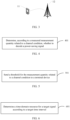
- FIG. 4 is a flowchart of a power-saving signal detecting method according to an embodiment of the present disclosure. As shown in FIG. 4 , the method includes the following steps:
- Step 401 Determine, according to a measured measurement quantity related to a channel condition, whether to detect a power-saving signal.
- the foregoing power-saving signal may be a signal transmitted on a PDCCH, or a sequence-based signal, where the foregoing sequence-based signal may be a CSI-RS, a PSS, an SSS, a TRS, a DMRS, or the like.
- the foregoing measurement quantity related to a channel condition may be set properly according to an actual need.
- the foregoing measurement quantity related to a channel condition may include but are not limited to at least one of the following:
- Reference signal received power RSRP measurement related to a change of RSRP
- reference signal reception quality RSRQ measurement related to a change of RSRQ
- signal to interference plus noise ratio SINR measurement related to a change of SINR
- mobility related measurement measurement related to a change of SINR
- measurement quantity related to a change of RSRP may all be set properly according to an actual need.
- the foregoing measurement quantity related to a change of RSRP may be a variance or a standard deviation of RSRP obtained by means of multiple measurements, for example, a variance or a standard deviation of all RSRP measured during a period of time; a difference between or a ratio of a value of RSRP measured currently to a value of RSRP measured previously, or the like.
- the foregoing measurement related to a change of RSRQ may be a variance or a standard deviation of RSRQ obtained by means of multiple measurements, for example, a variance or a standard deviation of all RSRQ measured during a period of time; a difference between or a ratio of a value of RSRQ measured currently to a value of RSRP measured previously, or the like.
- the foregoing measurement quantity related to a change of SINR may be a variance or a standard deviation of SINRs obtained by means of multiple measurements, for example, a variance or a standard deviation of all SINRs measured during a period of time; a difference between or a ratio of a value of SINR measured currently to a value of SINR measured previously, or the like.
- the foregoing measurement quantity related to mobility may be an indicator used to measure mobility of the terminal device.
- the measurement quantity related to mobility may include, but is not limited to, at least one of the following:
- the foregoing first preset time, second preset time, and third preset time may all be set properly according to an actual need, which is not limited in this embodiment.
- the power-saving signal may be detected in the case that an indicator signal condition of the measured measurement quantity related to a channel condition is good, so as to reduce power consumption of the terminal device, and it is not required to detect the power-saving signal in the case that an indicator signal condition of the measured measurement quantity related to a channel condition is poor, so as to improve the communication reliability.
- the power-saving signal detecting method provided in this embodiment of the present disclosure determines, according to a measured measurement quantity related to a channel condition, whether to detect a power-saving signal, and standardizes a way of detecting a power-saving signal, which can not only reduce power consumption of a terminal device, but also improve the communication reliability.
- the determining, according to a measured measurement quantity related to a channel condition, whether to detect a power-saving signal may include at least one of the following:
- the foregoing threshold corresponds to the measurement quantity related to a channel condition.
- the foregoing threshold may include a threshold for the RSRP; if the foregoing measurement quantity related to a channel condition includes RSRQ, the foregoing threshold may include a threshold for the RSRQ; if the foregoing measurement quantity related to a channel condition includes RSRP and RSRQ, the foregoing threshold may include a threshold for the RSRP and a threshold for the RSRQ.
- the foregoing threshold may be predefined in a protocol or configured by a network side device.
- the power-saving signal may be detected to reduce power consumption of the terminal device. For example, in the case that the measured RSRP is larger than or equal to a first threshold, the power-saving signal may be detected; in the case that the measured measurement quantity related to a channel condition fails to satisfy a threshold, it indicates that the channel condition is not good. At this time, it is possible not to require detecting the power-saving signal, but a PDCCH associated with the power-saving signal may be detected, so as to improve the communication stability. For example, in the case that the measured RSRP is less than a first threshold, it is possible not to require detecting the power-saving signal, but a PDCCH associated with the power-saving signal may be detected.
- the foregoing skipping requiring detecting the power-saving signal may mean that the terminal device may detect the power-saving signal, or may not detect the power-saving signal.
- the foregoing PDCCH associated with the power-saving signal may include a PDCCH carrying paging information, or a PDCCH located at OnDuration in a DRX cycle.
- the foregoing PDCCH associated with the power-saving signal may be a PDCCH carrying paging information
- RRC _CONNECTED state the foregoing PDCCH associated with the power-saving signal may be a PDCCH located at OnDuration in a DRX cycle.
- the measured measurement quantity related to a channel condition satisfies a threshold requirement may include at least one of the following:
- first threshold, second threshold, third threshold, fourth threshold, fifth threshold, sixth threshold, and seventh threshold may all be predefined in a protocol or configured on a network side, which is not limited in this embodiment.
- the foregoing measured measurement quantity related to mobility satisfies a third threshold requirement may include, but is not limited to: a number of cells on which the terminal device camps during a first preset time is less than or equal to the third threshold; or a number of beams on which the terminal device camps during a second preset time is less than or equal to the third threshold; or a movement velocity of the terminal device is less than or equal to the third threshold; or a Doppler frequency shift of the terminal device is less than or equal to the third threshold; or a number of TCI states of the terminal device during a third preset time is less than or equal to the third threshold, or the like.
- That the foregoing measured measurement quantity related to a change of RSRP satisfies a fourth threshold requirement may include, but is not limited to, that a variance of the measured RSRP is less than or equal to the fourth threshold.
- That the foregoing measured measurement quantity related to a change of RSRQ satisfies a fifth threshold requirement may include, but is not limited to, that a variance of the measured RSRQ is less than or equal to the fifth threshold.
- That the foregoing measured measurement quantity related to a change of SINR satisfies a seventh threshold requirement may include, but is not limited to, that a variance of the measured SINR is less than or equal to the seventh threshold.
- FIG. 5 is a flowchart of a power-saving signal detecting method according to an embodiment of the present disclosure. As shown in FIG. 5 , the method includes the following steps:
- Step 501 Send a threshold for the measurement quantity related to a channel condition to a terminal device.
- the foregoing threshold corresponds to the measurement quantity related to a channel condition.
- the foregoing threshold may include a threshold for the RSRP; if the foregoing measurement quantity related to a channel condition includes RSRQ, the foregoing threshold may include a threshold for the RSRQ; if the foregoing measurement quantity related to a channel condition includes RSRP and RSRQ, the foregoing threshold may include a threshold for the RSRP and a threshold for the RSRQ.
- the threshold for a measurement quantity related to a channel condition is sent to the terminal device, so that the terminal device may determine whether to detect a power-saving signal based on the threshold for a measurement quantity related to a channel condition.
- the measurement quantity related to a channel condition may include, but is not limited to, at least one of the following: reference signal received power RSRP, an measurement quantity related to a change of RSRP, reference signal received quality RSRQ, an measurement quantity related to a change of RSRQ, a signal-to-interference plus noise ratio SINR, a measurement quantity related to a change of SINR, and a measurement quantity related to mobility.
- measurement quantity related to a change of RSRP may all be set properly according to an actual need.
- the foregoing measurement quantity related to a change of RSRP may be a variance or a standard deviation of RSRP obtained by means of multiple measurements, for example, a variance or a standard deviation of all RSRP measured during a period of time; a difference between or a ratio of a value of RSRP measured currently to a value of RSRP measured previously, or the like.
- the foregoing measurement related to a change of RSRQ may be a variance or a standard deviation of RSRQ obtained by means of multiple measurements, for example, a variance or a standard deviation of all RSRQ measured during a period of time; a difference between or a ratio of a value of RSRQ measured currently to a value of RSRP measured previously, or the like.
- the foregoing measurement quantity related to a change of SINR may be a variance or a standard deviation of SINRs obtained by means of multiple measurements, for example, a variance or a standard deviation of all SINRs measured during a period of time; a difference between or a ratio of a value of SINR measured currently to a value of SINR measured previously, or the like.
- the foregoing measurement quantity related to mobility may be an indicator used to measure mobility of the terminal device.
- the measurement quantity related to mobility may include, but is not limited to, at least one of the following:
- the foregoing first preset time, second preset time, and third preset time may all be set properly according to an actual need, which is not limited in this embodiment.
- the UE may determine whether to detect a power-saving signal according to a measurement quantity related to a channel condition obtained from the most recent one or more measurements, for example, at least one of RSRP of a serving cell, RSRQ of a serving cell, and a measurement quantity related to mobility.
- a measurement quantity related to a channel condition obtained from the most recent one or more measurements, for example, at least one of RSRP of a serving cell, RSRQ of a serving cell, and a measurement quantity related to mobility.
- the power-saving signal is detected; otherwise (that is, the measured L1 or L3 RSRP fails to satisfy the first threshold), it is not required to detect the power-saving signal; at this time, the UE may detect a PDCCH.
- Table 1 RSRP from the last measurement or multiple historical measurements (dB)
- the foregoing skipping requiring detecting the power-saving signal may mean that the UE may detect the power-saving signal, or not detect the power-saving signal.
- the foregoing PDCCH may be a paging (that is, Paging) PDCCH for an RRC_IDLE state or RRC_INACTIVE state, and may be a PDCCH at OnDuration in a DRX cycle for an RRC_CONNECTED state. The same applies below and will not be repeated.
- the foregoing first threshold may be predefined in a protocol or configured on a network side, which is not limited in this embodiment.
- the power-saving signal is detected; otherwise (that is, the measured RSRQ fails to satisfy the threshold), it is not required to detect the power-saving signal; at this time, the UE may detect a PDCCH.
- the foregoing second threshold may be predefined in a protocol or configured on a network side, which is not limited in this embodiment.
- the power-saving signal is detected; otherwise (that is, the measured measurement quantity related to mobility fails to satisfy the third threshold), it is not required to detect the power-saving signal; at this time, the UE may detect a PDCCH.
- the power-saving signal may be detected in the case that a measurement quantity related to mobility M from the last measurement or multiple historical measurements satisfies a third threshold Z, it is not required to detect the power-saving signal.
- the foregoing third threshold may be predefined in a protocol or configured on a network side, which is not limited in this embodiment.
- the foregoing measurement quantity related to mobility may include one of the following:
- the power-saving signal is detected; otherwise, it is not required to detect the power-saving signal.
- the power-saving signal is detected; otherwise, it is not required to detect the power-saving signal.
- the power-saving signal is detected; otherwise (that is, the RSRP and RSRQ fail to satisfy the thresholds at the same time), it is not required to detect the power-saving signal; at this time, the UE may detect a PDCCH.
- the power-saving signal may be detected in the case that RSRP from the last measurement or multiple historical measurements is larger than or equal to a first threshold X and RSRQ is larger than or equal to a second threshold Y, otherwise, it is not required to detect the power-saving signal.
- the power-saving signal is detected; otherwise (that is, the RSRP and measurement quantity related to mobility fail to satisfy the thresholds at the same time), it is not required to detect the power-saving signal; at this time, the UE may detect a PDCCH.
- the power-saving signal may be detected in the case that RSRP from the last measurement or multiple historical measurements is larger than or equal to a first threshold X and a measurement quantity related to mobility M satisfies a third threshold Z, otherwise, it is not required to detect the power-saving signal.
- the foregoing measurement quantity related to mobility may include one of the following:
- the power-saving signal is detected; otherwise, it is not required to detect the power-saving signal.
- measured RSRP is larger than or equal to a first threshold, and a number of changes in cells on which the UE camps during a period of time is less than a third threshold, the power-saving signal is detected; otherwise, it is not required to detect the power-saving signal.
- the power-saving signal is detected; otherwise (that is, a measurement quantity related to a change of the RSRP or a measurement quantity related to a change of the RSRQ fails to satisfy the threshold), it is not required to detect the power-saving signal; at this time, the UE may detect a PDCCH.
- the foregoing measurement quantity related to a change of RSRP may be a variance or a standard deviation of RSRP from multiple historical measurements, a difference between or a ratio of RSRP measured currently to RSRP measured previously, or the like.
- the foregoing measurement quantity related to a change of RSRQ may be a variance or a standard deviation of RSRQ from multiple historical measurements, a difference between or a ratio of RSRQ measured currently to RSRQ measured previously, or the like.
- the power-saving signal may be detected in the case that a variance N of RSRP from multiple historical measurements is less than or equal to a fourth threshold P, otherwise, it is not required to detect the power-saving signal.
- both the foregoing fourth threshold and fifth threshold may be predefined in a protocol or configured on a network side, which is not limited in this embodiment.
- the power-saving signal detecting method provided in this embodiment of the present disclosure standardizes a UE's related behaviors of detecting a power-saving signal, where the power-saving signal may be detected in the case that a channel condition is good, which can reduce power consumption of the terminal, it is not required to detect the power-saving signal in the case that a channel condition is poor, and instead, the PDCCH is directly detected, so as to ensure reliability.
- FIG. 6 is a flowchart of a resource determining method according to an embodiment of the present disclosure. As shown in FIG. 6 , the method includes the following steps:
- Step 601 Determine a time-domain resource for a target signal according to a target time interval; where the target time interval includes at least one of a first time interval, a second time interval, and a third time interval; where the first time interval is a time interval between a power-saving signal and a PDCCH associated with the power-saving signal, the second time interval is a time interval between the power-saving signal and a first signal, and the third time interval is a time interval between the PDCCH associated with the power-saving signal and the first signal, the first signal is a signal used for downlink synchronization or radio resource management RRM measurement or beam management, and the target signal includes at least one of the power-saving signal and the first signal.
- the target time interval includes at least one of a first time interval, a second time interval, and a third time interval
- the first time interval is a time interval between a power-saving signal and a PDCCH associated with the power-saving signal
- the second time interval is a time interval between the power-saving signal and
- the foregoing power-saving signal may be a signal transmitted on a PDCCH, or a sequence-based signal, where the foregoing sequence-based signal may be a CSI-RS, a PSS, an SSS, a TRS, a DMRS, or the like.
- the foregoing PDCCH associated with the power-saving signal may include a PDCCH carrying paging information, a PDCCH located at OnDuration in a DRX cycle, or the like.
- the foregoing PDCCH associated with the power-saving signal may be a PDCCH carrying paging information
- RRC_CONNECTED state the foregoing PDCCH associated with the power-saving signal may be a PDCCH located at OnDuration in a DRX cycle.
- the foregoing first signal may be a signal used for downlink synchronization, RRM measurement or beam management, such as a CSI-RS, a PSS, an SSS, a TRS, or a DMRS.
- the terminal device may perform synchronization or RRM measurement or beam management according to a CSI-RS, a TRS, or the like, so as to facilitate reception of the power-saving signal.
- the foregoing target signal may include at least one of the power-saving signal and the first signal.
- the time-domain resource for the power-saving signal and/or the first signal may be determined before the power-saving signal is detected, so as to facilitate subsequent reception of the power-saving signal.
- first time interval, second time interval, and third time interval may all include one or at least two time intervals, which is not limited in this embodiment.
- the resource determining method provided in this embodiment of the present disclosure determines a time-domain resource for a target signal according to a target time interval, and standardizes a way of determining a resource related to power-saving signal detecting, so as to facilitate subsequent reception of a power-saving signal.
- the target time interval may be predefined in a protocol, or may be configured by a network side device.
- the method may further include:
- the terminal device reports the capability information of the terminal device to the network side device, so that the network side device can configure a target time interval for the terminal device based on the foregoing capability information. That is, the target time interval may be configured by the network side device based on the capability information of the terminal device.
- the foregoing fourth time interval, fifth time interval, and sixth time interval may correspond to the foregoing first time interval, second time interval, and third time interval respectively.
- the network side device may configure a first time interval for the terminal device based on the fourth time interval, where the first time interval may be larger than or equal to the fourth time interval; in the case that the terminal device reports a fifth time interval to the network side device, the network side device may configure a second time interval for the terminal device based on the fifth time interval, where the second time interval may be larger than or equal to the fifth time interval; in the case that the terminal device reports a sixth time interval to the network side device, the network side device may configure a third time interval for the terminal device based on the sixth time interval, where the third time interval may be larger than or equal to the sixth time interval.
- fourth time interval, fifth time interval, and sixth time interval may all include one or at least two time intervals, which is not limited in this embodiment.
- the capability information of the terminal device is reported to the network side device, which facilitates more accurate configuration of the target time interval for the terminal device by the network side device.
- the first time interval or the fourth time interval includes at least two different time intervals; where the two different time intervals correspond to a first scenario and a second scenario respectively, where the first scenario is that a bandwidth part (Bandwidth Part, BWP) where the power-saving signal is located is different from a BWP where the PDCCH associated with the power-saving signal is located, and the second scenario is that a BWP where the power-saving signal is located is the same as a BWP where the PDCCH associated with the power-saving signal is located.
- BWP Bandwidth Part
- that the BWP where the foregoing power-saving signal is located is different from the BWP where the PDCCH associated with the power-saving signal is located may include that at least one of a center frequency and a resource block (Resource Block, RB) of the BWP where the foregoing power-saving signal is located and the BWP where the PDCCH associated with the power-saving signal is located is different.
- Resource Block Resource Block
- the BWP where the foregoing power-saving signal is located is different from the BWP where the PDCCH associated with the power-saving signal is located is that a center frequency of the BWP where the foregoing power-saving signal is located is different from a center frequency of the BWP where the PDCCH associated with the power-saving signal is located
- that the BWP where the power-saving signal is located is the same as the BWP where the PDCCH associated with the power-saving signal may be that a center frequency of the BWP where the foregoing power-saving signal is located may be the same as a center frequency of the BWP where the PDCCH associated with the power-saving signal is located.
- the BWP where the foregoing power-saving signal is located is different from the BWP where the PDCCH associated with the power-saving signal is located is that an RB of the BWP where the foregoing power-saving signal is located is different from an RB of the BWP where the PDCCH associated with the power-saving signal is located
- that the BWP where the power-saving signal is located is the same as the BWP where the PDCCH associated with the power-saving signal is located may be that an RB of the BWP where the foregoing power-saving signal is located is the same as an RB of the BWP where the PDCCH associated with the power-saving signal is located.
- the second time interval or the fifth time interval includes at least two different time intervals; where the two different time intervals correspond to a third scenario and a fourth scenario respectively, where the third scenario is that a BWP where the power-saving signal is located is different from a BWP where the first signal is located, and the fourth scenario is that a BWP where the power-saving signal is located is the same as a BWP where the first signal is located.
- that the BWP where the foregoing power-saving signal is located is different from the BWP where the first signal is located may include that at least one of a center frequency and an RB of the BWP where the foregoing power-saving signal is located and the BWP where the first signal is located is different.
- the BWP where the foregoing power-saving signal is located is different from the BWP where the first signal is located is that a center frequency of the BWP where the foregoing power-saving signal is located is different from a center frequency of the BWP where the first signal is located
- that the BWP where the power-saving signal is located is the same as the BWP where the PDCCH associated with the power-saving signal is located may be that a center frequency of the BWP where the foregoing power-saving signal is located is the same as a center frequency of the BWP where the first signal is located.
- the BWP where the foregoing power-saving signal is located is different from the BWP where the first signal is located is that an RB of the BWP where the foregoing power-saving signal is located is different from an RB of the BWP where the first signal is located
- that the BWP where the power-saving signal is located is the same as the BWP where the PDCCH associated with the power-saving signal is located may be that an RB of the BWP where the foregoing power-saving signal is located is the same as an RB of the BWP where the first signal is located.
- the third time interval or the sixth time interval includes at least two different time intervals; where the two different time intervals correspond to a fifth scenario and a sixth scenario respectively, where the fifth scenario is that a BWP where the PDCCH associated with the power-saving signal is located is different from a BWP where the first signal is located, and the sixth scenario is that a BWP where the PDCCH associated with the power-saving signal is located is the same as a BWP where the first signal is located.
- that the BWP where the first signal is located is different from the BWP where the PDCCH associated with the power-saving signal is located may include that at least one of a center frequency and an RB of the BWP where the foregoing first signal is located and the BWP where the PDCCH associated with the power-saving signal is located is different.
- the BWP where the foregoing first signal is located is different from the BWP where the PDCCH associated with the power-saving signal is located is that a center frequency of the BWP where the foregoing first signal is located is different from a center frequency of the BWP where the PDCCH associated with the power-saving signal is located
- that the BWP where the first signal is located is the same as the BWP where the PDCCH associated with the power-saving signal may be that a center frequency of the BWP where the foregoing first signal is located may be the same as a center frequency of the BWP where the PDCCH associated with the power-saving signal is located.
- the BWP where the foregoing first signal is located is different from the BWP where the PDCCH associated with the power-saving signal is located is that an RB of the BWP where the foregoing first signal is located is different from an RB of the BWP where the PDCCH associated with the power-saving signal is located
- that the BWP where the first signal is located is the same as the BWP where the PDCCH associated with the power-saving signal is located may be that an RB of the BWP where the foregoing first signal is located is the same as an RB of the BWP where the PDCCH associated with the power-saving signal is located.
- the BWP where the foregoing first signal is located is different from the BWP where the PDCCH associated with the power-saving signal is located is that a center frequency of the BWP where the foregoing first signal is located is different from a center frequency of the BWP where the PDCCH associated with the power-saving signal is located, and an RB of the BWP where the foregoing first signal is located is different from an RB of the BWP where the PDCCH associated with the power-saving signal is located
- that the BWP where the first signal is located is the same as the BWP where the PDCCH associated with the power-saving signal may be that at least one of the following is the same: a center frequency of the BWP where the foregoing first signal is located and a center frequency of the BWP where the PDCCH associated with the power-saving signal is located, and an RB of the BWP where the foregoing first signal is located and an RB of the BWP where the PDCCH associated with the power-saving signal is located
- the power-saving signal is a signal transmitted on a PDCCH or a sequence-based signal.
- downlink synchronization, RRM measurement or beam management may be performed according to a first signal (for example, a CSI-RS, a TRS, or the like) before the terminal device detects the power-saving signal transmitted based on a PDCCH.
- a first signal for example, a CSI-RS, a TRS, or the like
- the foregoing power-saving signal and the first signal may be a same signal, for example, the power-saving signal may be received from a CSI-RS, a TRS, or the like at the same time when downlink synchronization, RRM measurement or beam management is performed according to a certain CSI-RS, a TRS, or the like; the foregoing power-saving signal and the first signal may be different signals, for example, downlink synchronization, RRM measurement or beam management is performed through a first CSI-RS, and the power-saving signal is transmitted by using a second CSI-RS.
- the power-saving signal and the first signal are different signals in the case that the power-saving signal is a sequence-based signal.
- the power-saving signal may be received from a CSI-RS, a TRS, or the like at the same time when downlink synchronization, RRM measurement or beam management is performed according to a certain CSI-RS, a TRS, or the like.
- the sequence-based signal may include but is not limited to one of the following: a channel state information reference signal CSI-RS, a primary synchronization signal PSS, a secondary synchronization signal SSS, a tracking reference signal TRS, and a demodulation reference signal DMRS.
- CSI-RS channel state information reference signal
- PSS primary synchronization signal
- SSS secondary synchronization signal
- TRS tracking reference signal
- DMRS demodulation reference signal
- FIG. 7 is a flowchart of a resource determining method according to an embodiment of the present disclosure. As shown in FIG. 7 , the method includes the following steps:
- Step 701 Send the target time interval to the terminal device; where the target time interval includes at least one of a first time interval, a second time interval, and a third time interval; where the first time interval is a time interval between a power-saving signal and a PDCCH associated with the power-saving signal, the second time interval is a time interval between the power-saving signal and a first signal, and the third time interval is a time between the PDCCH associated with the power-saving signal and the first signal, the first signal is a sequence signal used for downlink synchronization or radio resource management RRM measurement or beam management.
- the foregoing power-saving signal may be a signal transmitted on a PDCCH, or a sequence-based signal, where the foregoing sequence-based signal may be a CSI-RS, a PSS, an SSS, a TRS, a DMRS, or the like.
- the foregoing PDCCH associated with the power-saving signal may include a PDCCH carrying paging information, a PDCCH located at OnDuration in a DRX cycle, or the like.
- the foregoing PDCCH associated with the power-saving signal may be a PDCCH carrying paging information
- RRC _CONNECTED state the foregoing PDCCH associated with the power-saving signal may be a PDCCH located at OnDuration in a DRX cycle.
- the foregoing first signal may be a signal used for downlink synchronization, RRM measurement or beam management, such as a CSI-RS, a PSS, an SSS, a TRS, or a DMRS.
- the terminal device may perform synchronization or RRM measurement or beam management according to a CSI-RS, a TRS, or the like, so as to facilitate reception of the power-saving signal.
- first time interval, second time interval, and third time interval may all include one or at least two time intervals, which is not limited in this embodiment.
- the resource determining method provided in this embodiment of the present disclosure sends a target time interval to a terminal device, so that the terminal device can determine at least one of a time-domain resource for a power-saving signal and a time-domain resource for a first signal based on the target time interval, so as to facilitate reception of the power-saving signal by the terminal device.
- the method may further include:
- the target time interval can be configured for the terminal device based on the foregoing capability information, that is, the target time interval may be configured by the network side device based on the capability information of the terminal device.
- the foregoing fourth time interval, fifth time interval, and sixth time interval may correspond to the foregoing first time interval, second time interval, and third time interval respectively.
- the network side device may configure a first time interval for the terminal device based on the fourth time interval, where the first time interval may be larger than or equal to the fourth time interval; in the case that the terminal device reports a fifth time interval to the network side device, the network side device may configure a second time interval for the terminal device based on the fifth time interval, where the second time interval may be larger than or equal to the fifth time interval; in the case that the terminal device reports a sixth time interval to the network side device, the network side device may configure a third time interval for the terminal device based on the sixth time interval, where the third time interval may be larger than or equal to the sixth time interval.
- fourth time interval, fifth time interval, and sixth time interval may all include one or at least two time intervals, which is not limited in this embodiment.
- the network side device by means of receiving the capability information of the terminal device, it is convenient for the network side device to configure a more accurate target time interval for the terminal device.
- the first time interval or the fourth time interval includes at least two different time intervals; where the two different time intervals correspond to a first scenario and a second scenario respectively, where the first scenario is that a bandwidth part BWP where the power-saving signal is located is different from a BWP where the PDCCH associated with the power-saving signal is located, and the second scenario is that a BWP where the power-saving signal is located is the same as a BWP where the PDCCH associated with the power-saving signal is located.
- that the BWP where the power-saving signal is located is different from the BWP where the PDCCH associated with the power-saving signal is located may include that at least one of a center frequency and an RB of the BWP where the foregoing power-saving signal is located and the BWP where the PDCCH associated with the power-saving signal is located is different.
- the second time interval or the fifth time interval includes at least two different time intervals; where the two different time intervals correspond to a third scenario and a fourth scenario respectively, where the third scenario is that a BWP where the power-saving signal is located is different from a BWP where the first signal is located, and the fourth scenario is that a BWP where the power-saving signal is located is the same as a BWP where the first signal is located.
- that the BWP where the foregoing power-saving signal is located is different from the BWP where the first signal is located may include that at least one of a center frequency and an RB of the BWP where the foregoing power-saving signal is located and the BWP where the first signal is located is different.
- the third time interval or the sixth time interval includes at least two different time intervals; where the two different time intervals correspond to a fifth scenario and a sixth scenario respectively, where the fifth scenario is that a BWP where the PDCCH associated with the power-saving signal is located is different from a BWP where the first signal is located, and the sixth scenario is that a BWP where the PDCCH associated with the power-saving signal is located is the same as a BWP where the first signal is located.
- that the BWP where the first signal is located is different from the BWP where the PDCCH associated with the power-saving signal is located may include that at least one of a center frequency and an RB of the BWP where the foregoing first signal is located and the BWP where the PDCCH associated with the power-saving signal is located is different.
- the power-saving signal is a signal transmitted on a PDCCH or a sequence-based signal.
- the power-saving signal and the first signal are different signals in the case that the power-saving signal is a sequence-based signal.
- the sequence-based signal may include but is not limited to one of the following: a channel state information reference signal CSI-RS, a primary synchronization signal PSS, a secondary synchronization signal SSS, a tracking reference signal TRS, and a demodulation reference signal DMRS.
- CSI-RS channel state information reference signal
- PSS primary synchronization signal
- SSS secondary synchronization signal
- TRS tracking reference signal
- DMRS demodulation reference signal
- the power-saving signal may be a signal transmitted based on a PDCCH, or a sequence-based signal (for example, a CSI-RS, a TRS, or the like).
- the terminal device may perform synchronization or RRM measurement or beam management according to a CSI-RS, a TRS, or the like, so as to facilitate reception of the power-saving signal.
- the following three scenarios may be included:
- the resource determining method according to this embodiment of the present disclosure may include the following steps:
- the fourth time interval between the power-saving signal and the PDCCH associated with the power-saving signal reported by the UE to the base station may include multiple types of time intervals. For example, if a center frequency of the BWP where the power-saving signal is located is different that of the BWP where the PDCCH associated with the power-saving signal is located, the UE reports a time interval A; and if their center frequencies are the same, the UE reports a time interval B.
- the fifth time interval between the power-saving signal and the CSI-RS used for downlink synchronization, RRM measurement or beam management reported by the UE to the base station may also include multiple types of time intervals. For example, if a center frequency of the BWP where the power-saving signal is located is different that of the BWP where the CSI-RS used for downlink synchronization, RRM measurement or beam management is located, the UE reports a time interval C; and if their center frequencies are the same, the UE reports a time interval D.
- the sixth time interval between the PDCCH associated with the power-saving signal and the CSI-RS used for downlink synchronization, RRM measurement or beam management reported by the UE to the base station may also include multiple types of time intervals. For example, if a center frequency of the BWP where the PDCCH associated with the power-saving signal is located is different that of the BWP where the CSI-RS used for downlink synchronization, RRM measurement or beam management is located, the UE reports a time interval E; and if their center frequencies are the same, the UE reports a time interval F.
- the foregoing first time interval may also be predefined in a protocol.
- one default time interval is defined for each of two scenarios that the BWP where the power-saving signal is located and the BWP where the PDCCH associated with the power-saving signal is located are the same or different.
- the foregoing second time interval may also be predefined in a protocol.
- one default time interval is defined for each of two scenarios that the BWP where the power-saving signal is located and the BWP where the CSI-RS used for downlink synchronization, RRM measurement or beam management is located are the same or different.
- the foregoing third time interval may also be predefined in a protocol.
- one default time interval is defined for each of two scenarios that the BWP where the PDCCH associated with the power-saving signal is located and the BWP where the CSI-RS used for downlink synchronization, RRM measurement or beam management is located are the same or different.
- FIG. 8 is a structural diagram of a terminal device according to an embodiment of the present disclosure.
- a terminal device 800 includes: a determining module 801, configured to determine, according to a measured measurement quantity related to a channel condition, whether to detect a power-saving signal.
- the measurement quantity related to a channel condition include at least one of the following: reference signal received power RSRP, an measurement quantity related to a change of RSRP, reference signal received quality RSRQ, an measurement quantity related to a change of RSRQ, a signal-to-interference plus noise ratio SINR, a measurement quantity related to a change of SINR, and a measurement quantity related to mobility.
- the measurement quantity related to mobility includes at least one of the following:
- the determining module is specifically configured for at least one of the following:
- the measured measurement quantity related to a channel condition satisfies a threshold requirement includes at least one of the following:
- the threshold is configured on a network side or predefined in a protocol.
- the terminal device 800 can implement the processes implemented by the terminal device in the foregoing power-saving signal detecting method embodiment. To avoid repetition, details are not described herein again.
- the determining module 801 is configured to determine, according to a measured measurement quantity related to a channel condition, whether to detect a power-saving signal.
- a way of detecting a power-saving signal is standardized, which can not only reduce power consumption of a terminal device, but also improve the communication reliability.
- FIG. 9 is a structural diagram of a network side device according to an embodiment of the present disclosure.
- a network side device 900 includes: a sending module 901, configured to send a threshold for a measurement quantity related to a channel condition to a terminal device.
- the measurement quantity related to a channel condition include at least one of the following: reference signal received power RSRP, an measurement quantity related to a change of RSRP, reference signal received quality RSRQ, an measurement quantity related to a change of RSRQ, a signal-to-interference plus noise ratio SINR, a measurement quantity related to a change of SINR, and a measurement quantity related to mobility.
- the measurement quantity related to mobility includes at least one of the following:
- the network side device 900 can implement the processes implemented by the network side device in the foregoing power-saving signal detecting method embodiment. To avoid repetition, details are not described herein again.
- the sending module 901 is configured to send a threshold for a measurement quantity related to a channel condition to the terminal device, so that the terminal device can determine, based on the threshold for a measurement quantity related to a channel condition, whether to detect the power-saving signal.
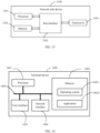
- FIG. 10 is a structural diagram of a terminal device according to yet another embodiment of the present disclosure.
- a terminal device 1000 includes:
- the target time interval is predefined in a protocol, or is configured by a network side device.
- the terminal device further includes:
- the target time interval is configured by the network side device based on the capability information of the terminal device.
- the first time interval or the fourth time interval includes at least two different time intervals; where the two different time intervals correspond to a first scenario and a second scenario respectively, where the first scenario is that a bandwidth part BWP where the power-saving signal is located is different from a BWP where the PDCCH associated with the power-saving signal is located, and the second scenario is that a BWP where the power-saving signal is located is the same as a BWP where the PDCCH associated with the power-saving signal is located.
- the second time interval or the fifth time interval includes at least two different time intervals; where the two different time intervals correspond to a third scenario and a fourth scenario respectively, where the third scenario is that a BWP where the power-saving signal is located is different from a BWP where the first signal is located, and the fourth scenario is that a BWP where the power-saving signal is located is the same as a BWP where the first signal is located.
- the third time interval or the sixth time interval includes at least two different time intervals; where the two different time intervals correspond to a fifth scenario and a sixth scenario respectively, where the fifth scenario is that a BWP where the PDCCH associated with the power-saving signal is located is different from a BWP where the first signal is located, and the sixth scenario is that a BWP where the PDCCH associated with the power-saving signal is located is the same as a BWP where the first signal is located.
- the power-saving signal is a signal transmitted on a PDCCH or a sequence-based signal.
- the power-saving signal and the first signal are different signals in the case that the power-saving signal is a sequence-based signal.
- the sequence-based signal includes one of the following: a channel state information reference signal CSI-RS, a primary synchronization signal PSS, a secondary synchronization signal SSS, a tracking reference signal TRS, and a demodulation reference signal DMRS.
- CSI-RS channel state information reference signal
- PSS primary synchronization signal
- SSS secondary synchronization signal
- TRS tracking reference signal
- DMRS demodulation reference signal
- the terminal device 1000 can implement the processes implemented by the terminal device in the foregoing resource determining method embodiment. To avoid repetition, details are not described herein again.
- the determining module 1001 is configured to determine a time-domain resource for a target signal according to a target time interval; where the target time interval includes at least one of a first time interval, a second time interval, and a third time interval; where the first time interval is a time interval between a power-saving signal and a PDCCH associated with the power-saving signal, the second time interval is a time interval between the power-saving signal and a first signal, and the third time interval is a time interval between the PDCCH associated with the power-saving signal and the first signal, the first signal is a signal used for downlink synchronization or radio resource management RRM measurement or beam management, and the target signal includes at least one of the power-saving signal and the first signal.
- a way of determining a resource related to power-saving signal detecting is standardized, so as to facilitate subsequent reception of a power-saving signal.
- FIG. 11 is a structural diagram of a network side device according to yet another embodiment of the present disclosure. As shown in FIG. 11 , the network side device 1100 includes:
- the network side device further includes:
- the target time interval is determined according to the capability information of the terminal device.
- the first time interval or the fourth time interval includes at least two different time intervals; where the two different time intervals correspond to a first scenario and a second scenario respectively, where the first scenario is that a bandwidth part BWP where the power-saving signal is located is different from a BWP where the PDCCH associated with the power-saving signal is located, and the second scenario is that a BWP where the power-saving signal is located is the same as a BWP where the PDCCH associated with the power-saving signal is located.
- the second time interval or the fifth time interval includes at least two different time intervals; where the two different time intervals correspond to a third scenario and a fourth scenario respectively, where the third scenario is that a BWP where the power-saving signal is located is different from a BWP where the first signal is located, and the fourth scenario is that a BWP where the power-saving signal is located is the same as a BWP where the first signal is located.
- the third time interval or the sixth time interval includes at least two different time intervals; where the two different time intervals correspond to a fifth scenario and a sixth scenario respectively, where the fifth scenario is that a BWP where the PDCCH associated with the power-saving signal is located is different from a BWP where the first signal is located, and the sixth scenario is that a BWP where the PDCCH associated with the power-saving signal is located is the same as a BWP where the first signal is located.
- the power-saving signal is a signal transmitted on a PDCCH or a sequence-based signal.
- the power-saving signal and the first signal are different signals in the case that the power-saving signal is a sequence-based signal.
- the sequence-based signal includes one of the following: a channel state information reference signal CSI-RS, a primary synchronization signal PSS, a secondary synchronization signal SSS, a tracking reference signal TRS, and a demodulation reference signal DMRS.
- CSI-RS channel state information reference signal
- PSS primary synchronization signal
- SSS secondary synchronization signal
- TRS tracking reference signal
- DMRS demodulation reference signal
- the network side device 1100 can implement the processes implemented by the network side device in the foregoing resource determining method embodiment. To avoid repetition, details are not described herein again.
- the sending module 1101 is configured to send a target time interval to a terminal device; where the target time interval includes at least one of a first time interval, a second time interval, and a third time interval; where the first time interval is a time interval between a power-saving signal and a PDCCH associated with the power-saving signal, the second time interval is a time interval between the power-saving signal and a first signal, and the third time interval is a time between the PDCCH associated with the power-saving signal and the first signal, the first signal is a sequence signal used for downlink synchronization or radio resource management RRM measurement or beam management.
- the terminal device can determine at least one of a time-domain resource for a power-saving signal and a time-domain resource for a first signal based on the target time interval, so as to facilitate reception of the power-saving signal by the terminal device.
- FIG. 12 is a structural diagram of a terminal device according to yet another embodiment of the present disclosure.
- a terminal device 1200 includes but is not limited to components such as a radio frequency unit 1201, a network module 1202, an audio output unit 1203, an input unit 1204, a sensor 1205, a display unit 1206, a user input unit 1207, an interface unit 1208, a memory 1209, a processor 1210, and a power supply 1211.
- the terminal device may include more or fewer components than that shown in the figure, or a combination of some components, or an arrangement of different components.
- the terminal device includes but is not limited to a mobile phone, a tablet computer, a notebook computer, a palmtop computer, a vehicle-mounted terminal, a wearable device, a pedometer, or the like.
- the processor 1210 is configured to determine, according to a measured measurement quantity related to a channel condition, whether to detect a power-saving signal.
- This embodiment of the present disclosure determines, according to a measured measurement quantity related to a channel condition, whether to detect a power-saving signal, and standardizes a way of detecting a power-saving signal, which can not only reduce power consumption of a terminal device, but also improve the communication reliability.
- the measurement quantity related to a channel condition include at least one of the following: reference signal received power RSRP, an measurement quantity related to a change of RSRP, reference signal received quality RSRQ, an measurement quantity related to a change of RSRQ, a signal-to-interference plus noise ratio SINR, a measurement quantity related to a change of SINR, and a measurement quantity related to mobility.
- the measurement quantity related to mobility includes at least one of the following:
- processor 1210 is further configured to implement at least one of the following:
- the measured measurement quantity related to a channel condition satisfies a threshold requirement includes at least one of the following:
- the threshold is configured on a network side or predefined in a protocol.
- the radio frequency unit 1201 may be configured to receive and send signals in an information receiving and sending process or a calling process. Specifically, after receiving downlink data from a base station, the radio frequency unit 1201 sends the downlink data to the processor 1210 for processing, and sends uplink data to the base station.
- the radio frequency unit 1201 includes, but not limited to, an antenna, at least one amplifier, a transceiver, a coupler, a low noise amplifier, and a duplexer.
- the radio frequency unit 1201 may communicate with a network and another device by using a wireless communications system.
- the terminal device provides a user with wireless broadband Internet access through the network module 1202, for example, helps the user send and receive emails, browse web pages, and access streaming media.
- the audio output unit 1203 may convert audio data received by the radio frequency unit 1201 or the network module 1202 or stored in the memory 1209 into an audio signal and output the audio signal as a sound.
- the audio output unit 1203 may further provide audio output (for example, call signal receiving sound or message receiving sound) related to a specific function performed by the terminal device 1200.
- the audio output unit 1203 includes a speaker, a buzzer, a telephone receiver, and the like.
- the input unit 1204 is configured to receive audio or video signals.
- the input unit 1204 may include a graphics processor (Graphics Processing Unit, GPU) 12041 and a microphone 12042, and the graphics processing unit 12041 processes image data of a still picture or a video obtained by an image capture apparatus (for example, a camera) in an image capture mode or a video capture mode.
- a processed image frame can be displayed on the display unit 1206.
- An image frame processed by the graphics processing unit 12041 may be stored in the memory 1209 (or another storage medium) or sent by the radio frequency unit 1201 or the network module 1202.
- the microphone 12042 may receive a sound and can process such sound into audio data.
- the processed audio data may be converted, in a call mode, into a format that can be sent by using the radio frequency unit 1201 to a mobile communication base station, for outputting.
- the terminal device 1200 further includes at least one sensor 1205, such as an optical sensor, a motion sensor, and other sensors.
- the optical sensor includes an ambient light sensor and a proximity sensor.
- the ambient light sensor may adjust luminance of the display panel 12061 based on brightness of ambient light.
- the proximity sensor may turn off the display panel 12061 and/or backlight when the terminal device 1200 approaches an ear.
- an accelerometer sensor may detect an acceleration in each direction (generally, three axes), and detect a value and a direction of gravity when the accelerometer sensor is static, and may be configured to recognize a terminal device posture (such as screen switching between landscape and portrait modes, a related game, or magnetometer posture calibration), a function related to vibration recognition (such as a pedometer or a knock), and the like.
- the sensor 1205 may further include a fingerprint sensor, a pressure sensor, an iris sensor, a molecular sensor, a gyroscope, a barometer, a hygrometer, a thermometer, and an infrared sensor. Details are not described herein.
- the display unit 1206 is configured to display information entered by a user or information provided for a user.
- the display unit 1206 may include the display panel 12061, and the display panel 12061 may be configured in a form of a liquid crystal display (Liquid Crystal Display, LCD), an organic light-emitting diode (Organic Light-Emitting Diode, OLED), or the like.
- LCD Liquid Crystal Display
- OLED Organic Light-Emitting Diode
- the user input unit 1207 may be configured to receive input numeral or character information, and generate key signal input related to user setting and function control of the terminal device.
- the user input unit 1207 includes a touch panel 12071 and another input device 12072.
- the touch panel 12071 is also referred to as a touchscreen, and may collect a touch operation of the user on or near the touch panel (for example, an operation performed on or near the touch panel 12071 by the user by using any appropriate object or accessory such as a finger or a stylus).
- the touch panel 12071 may include two parts: a touch detection apparatus and a touch controller.
- the touch detection apparatus detects a touch position of a user, detects a signal brought by a touch operation, and transmits the signal to the touch controller.
- the touch controller receives touch information from the touch detection apparatus, converts the touch information into touch point coordinates, sends the touch point coordinates to the processor the processor 1210, and receives and executes a command from the processor 1210.
- the touch panel 12071 may be implemented by using a plurality of types such as a resistive type, a capacitive type, an infrared ray, and a surface acoustic wave.
- the user input unit 1207 may include the another input device 12072 in addition to the touch panel 12071.
- the another input device 12072 may include, but is not limited to, a physical keyboard, function keys (such as a volume control key and a switch key), a trackball, a mouse, and a joystick. Details are not described herein.
- the touch panel 12071 may cover the display panel 12061.
- the touch panel 12071 transmits the touch operation to the processor 1210 to determine a type of a touch event, and then the processor 1210 provides corresponding visual output on the display panel 12061 based on the type of the touch event.
- the touch panel 12071 and the display panel 12061 are configured as two independent components to implement input and output functions of the terminal device, in some embodiments, the touch panel 12071 and the display panel 12061 can be integrated to implement the input and output functions of the terminal device. Details are not limited herein.
- the interface unit 1208 is an interface for connecting an external apparatus to the terminal device 1200.
- the external apparatus may include a wired or wireless headset jack, an external power supply (or a battery charger) port, a wired or wireless data port, a storage card port, a port for connecting an apparatus having an identification module, an audio input/output (input/output, I/O) port, a video I/O port, a headset jack, or the like.
- the interface unit 1208 may be configured to receive an input (for example, data information or power) from an external apparatus and transmit the received input to one or more elements in the terminal device 1200, or transmit data between the terminal device 1200 and the external apparatus.
- the memory 1209 may be configured to store a software program and various data.
- the memory 1209 may mainly include a program storage area and a data storage area.
- the program storage area may store an operating system, an application program required for at least one function (such as an audio playing function and an image playing function, etc.) etc.
- the data storage area may store data (such as audio data and a phone book, etc.) created according to use of the mobile phone.
- the memory 1209 may include a high speed random access memory, and may further include a non-volatile memory, such as at least one magnetic disk memory device, a flash memory device, or other non-volatile solid state memory devices.
- the processor 1210 is a control center of the terminal device.
- the processor 1210 uses various interfaces and lines to connect all parts of the entire terminal device, and performs various functions and data processing of the terminal device by running or executing the software program and/or module stored in the memory 1209 and invoking data stored in the memory 1209, thereby performing overall monitoring on the terminal device.
- the processor 1210 may include one or more processing units.
- an application processor and a modem processor may be integrated into the processor 1210.
- the application processor mainly processes an operating system, a user interface, an application, and the like.
- the modem processor mainly processes wireless communication. It may be understood that the foregoing modem processor may not be integrated into the processor 1210.
- the terminal device 1200 may further include the power supply 1211 (such as a battery) supplying power to each component.
- the power supply 1211 may be logically connected to the processor 1210 by using a power management system, so as to implement functions such as charging management, discharging management and power consumption management by using the power management system.
- the terminal device 1200 includes some functional modules that are not shown. Details are not described herein.
- an embodiment of the present disclosure further provides a terminal device, including a processor 1210, a memory 1209, and a computer program stored in the memory 1209 and executable on the processor 1210.
- a terminal device including a processor 1210, a memory 1209, and a computer program stored in the memory 1209 and executable on the processor 1210.
- the computer program is executed by the processor 1210, each process of the embodiments of the foregoing power-saving signal detecting method is implemented, and the same technical effect can be achieved. To avoid repetition, details are not described herein again.
- FIG. 13 is a structural diagram of a network side device according to yet another embodiment of the present disclosure.
- a network side device 1300 includes a processor 1301, a memory 1302, a bus interface 1303, and a transceiver 1304, where the processor 1301, the memory 1302, and the transceiver 1304 are all connected to the bus interface 1303.
- the network side device 1300 further includes a computer program that is stored in the memory 1302 and executable on the processor 1301.
- the transceiver 1304 is configured to send a threshold for a measurement quantity related to a channel condition to a terminal device.
- the measurement quantity related to a channel condition include at least one of the following: reference signal received power RSRP, an measurement quantity related to a change of RSRP, reference signal received quality RSRQ, an measurement quantity related to a change of RSRQ, a signal-to-interference plus noise ratio SINR, a measurement quantity related to a change of SINR, and a measurement quantity related to mobility.
- the measurement quantity related to mobility includes at least one of the following:
- the embodiments of the present disclosure further provide a computer-readable storage medium.
- the computer-readable storage medium stores a computer program, and when a processor executes the computer program, the processes of the foregoing power-saving signal detecting method embodiment are implemented and the same technical effect can be achieved. To avoid repetition, details are not described herein again.
- the computer-readable storage medium includes a read-only memory (Read-only Memory, ROM for short), a random access memory (Random Access Memory, RAM for short), a magnetic disk, an optical disc, or the like.
- FIG. 14 is a structural diagram of a terminal device according to yet another embodiment of the present disclosure.
- a terminal device 1400 includes: at least one of a processor 1401, a memory 1402, at least one network interface 1404, and a user interface 1403.
- the components in the terminal device 1400 are coupled together through a bus system 1405.
- the bus system 1405 is configured to implement connection and communication between these components.
- the bus system 1405 also includes a power bus, a control bus, and a status signal bus.
- the memory 1402 stores the following element: an executable module or a data structure, a subset thereof, or an extended set thereof: an operating system 14021 and an application program 14022.
- the operating system 14021 includes various system programs, such as a framework layer, a core library layer, and a driver layer, and is configured to implement various basic services and process hardware-based tasks.
- the application program 14022 includes various application programs, for example, a media player (Media Player) and a browser (Browser), and is configured to implement various application services.
- a program implementing the method in the embodiments of the present disclosure may be included in the application program 14022.
- the terminal device 1400 further includes: a computer program stored in the memory 1402 and executable on the processor 1401, which may specifically be a computer program in the application program 14022.
- a computer program stored in the memory 1402 and executable on the processor 1401, which may specifically be a computer program in the application program 14022.
- the target time interval is predefined in a protocol, or is configured by a network side device.
- the computer program when being executed by the processor 1401, the computer program is further configured to:
- the target time interval is configured by the network side device based on the capability information of the terminal device.
- the first time interval or the fourth time interval includes at least two different time intervals; where the two different time intervals correspond to a first scenario and a second scenario respectively, where the first scenario is that a bandwidth part BWP where the power-saving signal is located is different from a BWP where the PDCCH associated with the power-saving signal is located, and the second scenario is that a BWP where the power-saving signal is located is the same as a BWP where the PDCCH associated with the power-saving signal is located.
- the second time interval or the fifth time interval includes at least two different time intervals; where the two different time intervals correspond to a third scenario and a fourth scenario respectively, where the third scenario is that a BWP where the power-saving signal is located is different from a BWP where the first signal is located, and the fourth scenario is that a BWP where the power-saving signal is located is the same as a BWP where the first signal is located.
- the third time interval or the sixth time interval includes at least two different time intervals; where the two different time intervals correspond to a fifth scenario and a sixth scenario respectively, where the fifth scenario is that a BWP where the PDCCH associated with the power-saving signal is located is different from a BWP where the first signal is located, and the sixth scenario is that a BWP where the PDCCH associated with the power-saving signal is located is the same as a BWP where the first signal is located.
- the power-saving signal is a signal transmitted on a PDCCH or a sequence-based signal.
- the power-saving signal and the first signal are different signals in the case that the power-saving signal is a sequence-based signal.
- the sequence-based signal includes one of the following: a channel state information reference signal CSI-RS, a primary synchronization signal PSS, a secondary synchronization signal SSS, a tracking reference signal TRS, and a demodulation reference signal DMRS.
- CSI-RS channel state information reference signal
- PSS primary synchronization signal
- SSS secondary synchronization signal
- TRS tracking reference signal
- DMRS demodulation reference signal
- FIG. 15 is a structural diagram of a network side device according to yet another embodiment of the present disclosure.
- a network side device 1500 includes a processor 1501, a memory 1502, a bus interface 1503, and a transceiver 1504, where the processor 1501, the memory 1502, and the transceiver 1504 are all connected to the bus interface 1503.
- the network side device 1500 further includes a computer program that is stored in the memory 1502 and executable on the processor 1501.
- the transceiver 1504 is configured to:
- the transceiver 1504 is further configured to:
- the target time interval is determined according to the capability information of the terminal device.
- the first time interval or the fourth time interval includes at least two different time intervals; where the two different time intervals correspond to a first scenario and a second scenario respectively, where the first scenario is that a bandwidth part BWP where the power-saving signal is located is different from a BWP where the PDCCH associated with the power-saving signal is located, and the second scenario is that a BWP where the power-saving signal is located is the same as a BWP where the PDCCH associated with the power-saving signal is located.
- the second time interval or the fifth time interval includes at least two different time intervals; where the two different time intervals correspond to a third scenario and a fourth scenario respectively, where the third scenario is that a BWP where the power-saving signal is located is different from a BWP where the first signal is located, and the fourth scenario is that a BWP where the power-saving signal is located is the same as a BWP where the first signal is located.
- the third time interval or the sixth time interval includes at least two different time intervals; where the two different time intervals correspond to a fifth scenario and a sixth scenario respectively, where the fifth scenario is that a BWP where the PDCCH associated with the power-saving signal is located is different from a BWP where the first signal is located, and the sixth scenario is that a BWP where the PDCCH associated with the power-saving signal is located is the same as a BWP where the first signal is located.
- the power-saving signal is a signal transmitted on a PDCCH or a sequence-based signal.
- the power-saving signal and the first signal are different signals in the case that the power-saving signal is a sequence-based signal.
- the sequence-based signal includes one of the following: a channel state information reference signal CSI-RS, a primary synchronization signal PSS, a secondary synchronization signal SSS, a tracking reference signal TRS, and a demodulation reference signal DMRS.
- CSI-RS channel state information reference signal
- PSS primary synchronization signal
- SSS secondary synchronization signal
- TRS tracking reference signal
- DMRS demodulation reference signal
- An embodiment of the present disclosure further provides a computer-readable storage medium.
- a computer program is stored in the computer-readable storage medium. When being executed by a processor, the computer program implements each process of the embodiment of the foregoing resource determining method, and a same technical effect can be achieved. To avoid repetition, details are not described herein.
- the computer-readable storage medium is, for example, a read-only memory (Read-Only Memory, ROM for short), a random access memory (Random Access Memory, RAM for short), a magnetic disk, or an optical disc.
- the foregoing methods in the embodiments may be implemented by using software plus a required universal hardware platform, or certainly may be implemented by using hardware. However, in many cases, the former is a better implementation.
- the technical solutions of the present disclosure essentially or the part contributing to the prior art may be implemented in a form of a software product.
- the computer software product is stored in a storage medium (such as a ROM/RAM, a hard disk, or an optical disc), and includes several instructions for instructing a terminal (which may be mobile phone, a computer, a server, an air conditioner, a network device, or the like) to perform the methods described in the embodiments of the present disclosure.
- the disclosed device and method may be implemented in other manners.
- the described device embodiment is merely an example.
- the unit division is merely logical function division and may be other division in actual implementation.
- a plurality of units or components may be combined or integrated into another system, or some features may be ignored or not performed.
- the displayed or discussed mutual couplings or direct couplings or communication connections may be implemented by using some interfaces.
- the indirect couplings or communication connections between the devices or units may be implemented in electronic, mechanical, or other forms.
- the units described as separate parts may or may not be physically separate, and parts displayed as units may or may not be physical units, that is, may be located in one location, or may be distributed on a plurality of network units. Some or all of the units may be selected based on actual requirements to achieve the objectives of the solutions of the embodiments.
- the function may be stored in a computer-readable storage medium.
- the computer software product is stored in a storage medium, and includes several instructions for enabling a computer device (which may be a personal computer, a server, a network device, or the like) to perform all or some of the steps of the methods described in the embodiments of the present disclosure.
- the storage medium includes various mediums, such as a USB flash disk, a removable hard disk, a ROM, a RAM, a magnetic disk, or an optical disc, that can store program code.
- the foregoing program may be stored in a computer-readable storage medium, where when the program is executed, the processes of the embodiments of the foregoing methods can be included.
- the foregoing storage medium may include: a magnetic disk, an optical disc, a read-only memory (Read-Only Memory, ROM), a random access memory (Random Access Memory, RAM), or the like.
- the embodiments described in the embodiments of the present disclosure may be implemented by hardware, software, firmware, middleware, microcode, or a combination thereof.
- the module, unit, and subunit may be implemented in one or more application specific integrated circuits (Application Specific Integrated Circuits, ASIC), a digital signal processor (Digital Signal Processing, DSP), a DSP device (DSP Device, DSPD), a programmable logic device (Programmable Logic Device, PLD), a field-programmable gate array (Field-Programmable Gate Array, FPGA), general processors, controllers, micro-controllers, micro-processors, and other electronic units for implementing the functions of the present application, or their combinations.
- ASIC Application Specific Integrated Circuits
- DSP Digital Signal Processing
- DSP Device DSP Device
- DSPD programmable logic device
- PLD programmable Logic Device
- FPGA field-programmable gate array
- general processors controllers, micro-controllers, micro-processors, and other electronic units for
- technologies described in the embodiments of the present disclosure may be implemented by executing functional modules (for example, a process and a function) in the embodiments of the present disclosure.
- Software code can be stored in the memory and executed by the processor.
- the memory can be implemented inside or outside the processor.
Landscapes
- Engineering & Computer Science (AREA)
- Computer Networks & Wireless Communication (AREA)
- Signal Processing (AREA)
- Mobile Radio Communication Systems (AREA)
Claims (14)
- Ressourcenbestimmungsverfahren, das auf eine Endgerätvorrichtung (11) angewendet wird, dadurch gekennzeichnet, dass es umfasst:Senden von Fähigkeitsinformationen der Endgerätvorrichtung (11) an eine netzwerkseitige Vorrichtung (12); worin die Fähigkeitsinformationen ein viertes Zeitintervall umfassen, und das vierte Zeitintervall ein Zeitintervall zwischen einem Energiesparsignal und dem PDCCH ist, der dem Energiesparsignal zugeordnet ist;Empfangen eines Ziel-Zeitintervalls von der netzwerkseitigen Vorrichtung (12);Bestimmen (601) einer Zeitbereichsressource für das Energiesparsignal gemäß dem Ziel-Zeitintervall;worin das Ziel-Zeitintervall zumindest eines umfasst von: einem ersten Zeitintervall, und das erste Zeitintervall ein Zeitintervall zwischen einem Energiesparsignal und einem physikalischen Downlink-Steuerkanal, PDCCH, ist, der dem Energiesparsignal zugeordnet ist.
- Verfahren nach Anspruch 1, worin das erste Zeitintervall oder das vierte Zeitintervall zumindest zwei verschiedene Zeitintervalle umfasst;
worin die zwei verschiedenen Zeitintervalle jeweils einem ersten Szenario und einem zweiten Szenario entsprechen, worin das erste Szenario ist, dass ein Bandbreitenteil, BWP, worin das Energiesparsignal gelegen ist, anders ist als ein BWP, worin der PDCCH, der dem Energiesparsignal zugeordnet ist, gelegen ist, und das zweite Szenario ist, dass ein BWP, worin das Energiesparsignal gelegen ist, gleich einem BWP ist, worin der PDCCH, der dem Energiesparsignal zugeordnet ist, gelegen ist. - Verfahren nach Anspruch 1, worin das Energiesparsignal ein Signal, das an einem PDCCH übertragen ist, oder ein sequenzbasiertes Signal ist; und/oderdas Energiesparsignal und das erste Signal verschiedene Signale in dem Falle sind, dass das Energiesparsignal ein sequenzbasiertes Signal ist; und/oderdas sequenzbasierte Signal eines von den folgenden umfasst: einem Kanalzustandsinformation-Referenzsignal, CSI-RS, einem primären Synchronisationssignal, PSS, einem sekundären Synchronisationssignal, SSS, einem Verfolgungs-Referenzsignal, TRS, und einem Demodulations-Referenzsignal, DMRS.
- Ressourcenbestimmungsverfahren, das auf eine netzwerkseitige Vorrichtung (12) angewendet wird, dadurch gekennzeichnet, dass es umfasst:Senden (701) eines Ziel-Zeitintervalls an eine Endgerätvorrichtung (11);worin das Ziel-Zeitintervall zumindest eines von einem ersten Zeitintervall, einem zweiten Zeitintervall und einem dritten Zeitintervall umfasst; worin das erste Zeitintervall ein Zeitintervall zwischen einem Energiesparsignal und einem physikalischen Downlink-Steuerkanal, PDCCH, ist, der dem Energiesparsignal zugeordnet ist, das zweite Zeitintervall ein Zeitintervall zwischen dem Energiesparsignal und einem ersten Signal ist, und das dritte Zeitintervall eine Zeit zwischen dem PDCH, der dem Energiesparsignal zugeordnet ist, und dem ersten Signal ist, das erste Signal ein Sequenzsignal ist, das für Downlink-Synchronisation oder Funkressourcenverwaltung, RRM,-Messung oder Strahlverwaltung benutzt wird;wobei das Verfahren ferner umfasst:Empfangen von Fähigkeitsinformationen der Endgerätvorrichtung (11) von der Endgerätvorrichtung (11);worin die Fähigkeitsinformationen ein viertes Zeitintervall umfassen; und das vierte Zeitintervall ein Zeitintervall zwischen dem Energiesparsignal und dem PDCCH ist, der dem Energiesparsignal zugeordnet ist.
- Verfahren nach Anspruch 4, worin das Ziel-Zeitintervall gemäß den Fähigkeitsinformationen der Endgerätvorrichtung (11) bestimmt wird.
- Verfahren nach Anspruch 5, worin das erste Zeitintervall oder das vierte Zeitintervall zumindest zwei verschiedene Zeitintervalle umfasst;
worin die zwei verschiedenen Zeitintervalle jeweils einem ersten Szenario und einem zweiten Szenario entsprechen, worin das erste Szenario ist, dass ein Bandbreitenteil, BWP, worin das Energiesparsignal gelegen ist, anders ist als ein BWP, worin der PDCCH, der dem Energiesparsignal zugeordnet ist, gelegen ist, und das zweite Szenario ist, dass ein BWP, worin das Energiesparsignal gelegen ist, gleich einem BWP ist, worin der PDCCH, der dem Energiesparsignal zugeordnet ist, gelegen ist. - Verfahren nach Anspruch 4, worin das Energiesparsignal ein Signal, das an einem PDCCH übertragen ist, oder ein sequenzbasiertes Signal ist; und/oderdas Energiesparsignal und das erste Signal verschiedene Signale in dem Falle sind, dass das Energiesparsignal ein sequenzbasiertes Signal ist; und/oderdas sequenzbasierte Signal eines von den folgenden umfasst: einem Kanalzustandsinformation-Referenzsignal, CSI-RS, einem primären Synchronisationssignal, PSS, einem sekundären Synchronisationssignal, SSS, einem Verfolgungs-Referenzsignal, TRS, und einem Demodulations-Referenzsignal, DMRS.
- Endgerätvorrichtung (1000), dadurch gekennzeichnet, dass sie umfasst:ein Sendemodul, das dazu eingerichtet ist, Fähigkeitsinformationen der Endgerätvorrichtung an eine netzwerkseitige Vorrichtung (1100) vor dem Bestimmen einer Zeitbereichsressource für ein Energiesparsignal gemäß einem Ziel-Zeitintervall zu senden;ein Empfangsmodul, das dazu eingerichtet ist, ein Ziel-Zeitintervall von der netzwerkseitigen Vorrichtung (1100) zu empfangen;ein Bestimmungsmodul (1001), das dazu eingerichtet ist, eine Zeitbereichsressource für das Energiesparsignal gemäß dem Ziel-Zeitintervall zu bestimmen;worin das Ziel-Zeitintervall ein erstes Zeitintervall umfasst, und das erste Zeitintervall ein Zeitintervall zwischen einem Energiesparsignal und einem physikalischen Downlink-Steuerkanal, PDCCH, ist, der dem Energiesparsignal zugeordnet ist.
- Endgerätvorrichtung (1000) nach Anspruch 8, worin das erste Zeitintervall oder das vierte Zeitintervall zumindest zwei verschiedene Zeitintervalle umfasst;
worin die zwei verschiedenen Zeitintervalle jeweils einem ersten Szenario und einem zweiten Szenario entsprechen, worin das erste Szenario ist, dass ein Bandbreitenteil, BWP, worin das Energiesparsignal gelegen ist, anders ist als ein BWP, worin der PDCCH, der dem Energiesparsignal zugeordnet ist, gelegen ist, und das zweite Szenario ist, dass ein BWP, worin das Energiesparsignal gelegen ist, gleich einem BWP ist, worin der PDCCH, der dem Energiesparsignal zugeordnet ist, gelegen ist. - Endgerätvorrichtung (1000) nach Anspruch 8, worin das Energiesparsignal ein Signal, das an einem PDCCH übertragen ist, oder ein sequenzbasiertes Signal ist; und/oderdas Energiesparsignal und das erste Signal verschiedene Signale in dem Falle sind, dass das Energiesparsignal ein sequenzbasiertes Signal ist; und/oderdas sequenzbasierte Signal eines von den folgenden umfasst: einem Kanalzustandsinformation-Referenzsignal, CSI-RS, einem primären Synchronisationssignal, PSS, einem sekundären Synchronisationssignal, SSS, einem Verfolgungs-Referenzsignal, TRS, und einem Demodulations-Referenzsignal, DMRS.
- Netzwerkseitige Vorrichtung (1100), dadurch gekennzeichnet, dass sie umfasst:ein Sendemodul (1101), das dazu eingerichtet ist, ein Ziel-Zeitintervall an eine Endgerätvorrichtung (1000) zu senden;worin das Ziel-Zeitintervall ein erstes Zeitintervall umfasst, und das erste Zeitintervall ein Zeitintervall zwischen einem Energiesparsignal und einem physikalischen Downlink-Steuerkanal, PDCCH, ist, der dem Energiesparsignal zugeordnet ist;ein Empfangsmodul, das dazu eingerichtet ist, Fähigkeitsinformationen der Endgerätvorrichtung (1000) von der Endgerätvorrichtung zu empfangen;wo die Fähigkeitsinformationen ein viertes Zeitintervall umfassen, und worin das vierte Zeitintervall ein Zeitintervall zwischen dem Energiesparsignal und dem PDCCH ist, der dem Energiesparsignal zugeordnet ist.
- Netzwerkseitige Vorrichtung (1100) nach Anspruch 11, worin das Ziel-Zeitintervall gemäß den Fähigkeitsinformationen der Endgerätvorrichtung (1000) bestimmt wird.
- Netzwerkseitige Vorrichtung (1100) nach Anspruch 12, worin das erste Zeitintervall oder das vierte Zeitintervall zumindest zwei verschiedene Zeitintervalle umfasst;
worin die zwei verschiedenen Zeitintervalle jeweils einem ersten Szenario und einem zweiten Szenario entsprechen, worin das erste Szenario ist, dass ein Bandbreitenteil, BWP, worin das Energiesparsignal gelegen ist, anders ist als ein BWP, worin der PDCCH, der dem Energiesparsignal zugeordnet ist, gelegen ist, und das zweite Szenario ist, dass ein BWP, worin das Energiesparsignal gelegen ist, gleich einem BWP ist, worin der PDCCH, der dem Energiesparsignal zugeordnet ist, gelegen ist. - Netzwerkseitige Vorrichtung (1100) nach Anspruch 11, worin das Energiesparsignal ein Signal, das an einem PDCCH übertragen ist, oder ein sequenzbasiertes Signal ist; und/oderdas Energiesparsignal und das erste Signal verschiedene Signale in dem Falle sind, dass das Energiesparsignal ein sequenzbasiertes Signal ist; und/oderdas sequenzbasierte Signal eines von den folgenden umfasst: einem Kanalzustandsinformation-Referenzsignal, CSI-RS, einem primären Synchronisationssignal, PSS, einem sekundären Synchronisationssignal, SSS, einem Verfolgungs-Referenzsignal, TRS, und einem Demodulations-Referenzsignal, DMRS.
Applications Claiming Priority (2)
| Application Number | Priority Date | Filing Date | Title |
|---|---|---|---|
| CN201910108019.0A CN111278027B (zh) | 2019-02-02 | 2019-02-02 | 节能信号检测方法、资源确定方法及相关设备 |
| PCT/CN2020/070911 WO2020156074A1 (zh) | 2019-02-02 | 2020-01-08 | 节能信号检测方法、资源确定方法及相关设备 |
Publications (3)
| Publication Number | Publication Date |
|---|---|
| EP3920575A1 EP3920575A1 (de) | 2021-12-08 |
| EP3920575A4 EP3920575A4 (de) | 2022-03-23 |
| EP3920575B1 true EP3920575B1 (de) | 2024-08-14 |
Family
ID=71001547
Family Applications (1)
| Application Number | Title | Priority Date | Filing Date |
|---|---|---|---|
| EP20749248.9A Active EP3920575B1 (de) | 2019-02-02 | 2020-01-08 | Energiesparsignaldetektionsverfahren, ressourcenbestimmungsverfahren und zugehörige vorrichtung |
Country Status (7)
| Country | Link |
|---|---|
| US (1) | US12484028B2 (de) |
| EP (1) | EP3920575B1 (de) |
| CN (1) | CN111278027B (de) |
| ES (1) | ES2987740T3 (de) |
| HU (1) | HUE068485T2 (de) |
| PT (1) | PT3920575T (de) |
| WO (1) | WO2020156074A1 (de) |
Families Citing this family (15)
| Publication number | Priority date | Publication date | Assignee | Title |
|---|---|---|---|---|
| US11012106B2 (en) * | 2016-09-23 | 2021-05-18 | Qualcomm Incorporated | Implementation of improved omni mode signal reception |
| CN111867015B (zh) * | 2019-04-30 | 2023-11-17 | 华为技术有限公司 | 检测或发送下行控制信道的方法和装置 |
| WO2020223654A1 (en) * | 2019-05-01 | 2020-11-05 | Apple Inc. | Control channel signaling for user equipment (ue) power saving |
| US11582796B2 (en) * | 2020-05-15 | 2023-02-14 | Qualcomm Incorporated | Listen-before-talk (LBT) failure detection in dormant cell and outside discontinuous reception (DRX) active time |
| WO2021253386A1 (zh) * | 2020-06-19 | 2021-12-23 | 深圳传音控股股份有限公司 | 降低功耗的方法、设备、系统及存储介质 |
| CN113939037A (zh) * | 2020-07-13 | 2022-01-14 | 中国移动通信有限公司研究院 | 一种终端接入方法、终端及存储介质 |
| CN115699898B (zh) * | 2020-08-14 | 2025-05-06 | Oppo广东移动通信有限公司 | 信息处理方法及装置、设备、计算机存储介质 |
| CN116368838A (zh) * | 2020-10-16 | 2023-06-30 | 中兴通讯股份有限公司 | 用于无线通信的方法、设备和计算机程序产品 |
| AU2021363640B2 (en) | 2020-10-23 | 2024-09-05 | Telefonaktiebolaget Lm Ericsson (Publ) | Employing paging early indicator for idle mode wireless communication device power savings |
| EP4271070A4 (de) * | 2021-01-15 | 2024-02-21 | Huawei Technologies Co., Ltd. | Funkrufanzeigeverfahren und -vorrichtung |
| US12010649B2 (en) * | 2021-07-30 | 2024-06-11 | Qualcomm Incorporated | Unified paging early indication design |
| CN116347494A (zh) * | 2021-12-22 | 2023-06-27 | 中国移动通信有限公司研究院 | 检测方法、装置、终端及存储介质 |
| CN117528669A (zh) * | 2022-07-28 | 2024-02-06 | 维沃移动通信有限公司 | 接收方法、终端、网络侧设备及介质 |
| CN118476256A (zh) * | 2022-12-07 | 2024-08-09 | 北京小米移动软件有限公司 | 唤醒信号接收发送方法和装置 |
| CN118524423A (zh) * | 2023-02-17 | 2024-08-20 | 维沃移动通信有限公司 | 低功耗终端的同步和测量方法、终端及网络侧设备 |
Family Cites Families (23)
| Publication number | Priority date | Publication date | Assignee | Title |
|---|---|---|---|---|
| GB2500260A (en) * | 2012-03-16 | 2013-09-18 | Renesas Mobile Corp | Comparing channel measurements for selecting discontinuous reception cycle lengths or intra-frequency neighbour cell measurement frequency |
| WO2018171476A1 (zh) * | 2017-03-22 | 2018-09-27 | 华为技术有限公司 | 用于传输数据的方法和终端设备 |
| US11134492B2 (en) * | 2017-04-12 | 2021-09-28 | Samsung Electronics Co., Ltd. | Method and apparatus for beam recovery in next generation wireless systems |
| FI3641412T3 (fi) | 2017-05-04 | 2024-01-09 | Guangdong Oppo Mobile Telecommunications Corp Ltd | Langaton viestintämenetelmä ja laite |
| US11564170B2 (en) * | 2017-05-04 | 2023-01-24 | Ipla Holdings Inc. | Wake up signals operation |
| US11297570B2 (en) * | 2017-05-05 | 2022-04-05 | Sony Corporation | Terminal device, infrastructure equipment, wireless telecommunications system and methods |
| CN109286968B (zh) * | 2017-07-20 | 2020-07-28 | 维沃移动通信有限公司 | 一种盲检测参数获取方法、相关设备及系统 |
| US11516735B2 (en) * | 2017-08-11 | 2022-11-29 | Telefonaktiebolaget Lm Ericsson (Publ) | Systems and methods for adaptively monitoring downlink control channel in discontinuous reception |
| WO2018171194A1 (zh) | 2017-10-30 | 2018-09-27 | 北京小米移动软件有限公司 | 随机接入方法及装置 |
| EP3689039A1 (de) * | 2017-12-19 | 2020-08-05 | Huawei Technologies Co. Ltd. | Benutzerknoten, netzwerkknoten und verfahren zur drahtlosen kommunikation |
| AU2018415388A1 (en) * | 2018-03-30 | 2020-11-19 | Guangdong Oppo Mobile Telecommunications Corp., Ltd. | Method and device for signal transmission |
| KR102450653B1 (ko) * | 2018-05-11 | 2022-10-06 | 광동 오포 모바일 텔레커뮤니케이션즈 코포레이션 리미티드 | 신호 전송 방법, 기지국 및 네트워크 노드 |
| US11197339B2 (en) * | 2018-06-15 | 2021-12-07 | Qualcomm Incorporated | Beamformed transmission of a C-DRX wakeup signal |
| US11224088B2 (en) * | 2018-07-02 | 2022-01-11 | Qualcomm Incorporated | Beam sweeping during an on-period of a DRX cycle |
| CN110892770B (zh) * | 2018-07-26 | 2023-12-29 | Oppo广东移动通信有限公司 | 传输信号的方法、网络设备和终端设备 |
| JP7232898B2 (ja) * | 2018-08-17 | 2023-03-03 | アイディーエーシー ホールディングス インコーポレイテッド | 無線通信における省電力信号 |
| CN109314869B (zh) * | 2018-08-24 | 2022-04-15 | 北京小米移动软件有限公司 | 非连续接收drx参数的配置方法及装置 |
| WO2020060890A1 (en) * | 2018-09-17 | 2020-03-26 | Apple Inc. | Systems, methods, and devices for signaling for power saving |
| US12167329B2 (en) * | 2018-09-27 | 2024-12-10 | Interdigital Patent Holdings, Inc. | Power saving mechanisms in NR |
| CN117858278A (zh) * | 2019-01-10 | 2024-04-09 | 北京三星通信技术研究有限公司 | 一种物理下行控制信道的监听方法、终端设备及存储介质 |
| EP3909305B1 (de) * | 2019-01-11 | 2025-08-06 | Lenovo (Singapore) Pte. Ltd. | Verfahren und vorrichtung mit einer konfiguration des diskontinuierlichen empfangs |
| EP4014689A4 (de) * | 2019-08-14 | 2023-09-13 | Hannibal IP LLC | Verfahren zum überwachen eines physikalischen downlink-steuerungskanals für ein leistungssparendes signal und zugehörige vorrichtung |
| US11533685B2 (en) * | 2019-08-16 | 2022-12-20 | Qualcomm Incorporated | Wake-up behavior indication for power saving |
-
2019
- 2019-02-02 CN CN201910108019.0A patent/CN111278027B/zh active Active
-
2020
- 2020-01-08 HU HUE20749248A patent/HUE068485T2/hu unknown
- 2020-01-08 ES ES20749248T patent/ES2987740T3/es active Active
- 2020-01-08 PT PT207492489T patent/PT3920575T/pt unknown
- 2020-01-08 WO PCT/CN2020/070911 patent/WO2020156074A1/zh not_active Ceased
- 2020-01-08 EP EP20749248.9A patent/EP3920575B1/de active Active
-
2021
- 2021-07-30 US US17/389,417 patent/US12484028B2/en active Active
Also Published As
| Publication number | Publication date |
|---|---|
| US20210360621A1 (en) | 2021-11-18 |
| WO2020156074A1 (zh) | 2020-08-06 |
| PT3920575T (pt) | 2024-09-11 |
| CN111278027B (zh) | 2021-11-30 |
| HUE068485T2 (hu) | 2024-12-28 |
| CN111278027A (zh) | 2020-06-12 |
| ES2987740T3 (es) | 2024-11-18 |
| EP3920575A1 (de) | 2021-12-08 |
| US12484028B2 (en) | 2025-11-25 |
| EP3920575A4 (de) | 2022-03-23 |
Similar Documents
| Publication | Publication Date | Title |
|---|---|---|
| EP3920575B1 (de) | Energiesparsignaldetektionsverfahren, ressourcenbestimmungsverfahren und zugehörige vorrichtung | |
| US20220399976A1 (en) | Method for sending, configuring, and measuring srs, positioning method, and device | |
| JP7285959B2 (ja) | チャネルモニタリング方法、端末及びネットワーク機器 | |
| EP4132072B1 (de) | Signalmessverfahren, messspaltkonfigurationsverfahren, messberichtsverfahren, endgerät, netzwerkvorrichtung und positionsverwaltungsvorrichtung | |
| KR102834777B1 (ko) | Pdcch 모니터링 방법 및 단말 | |
| CN110012524B (zh) | 时频同步方法、网络设备和终端 | |
| CN112533232B (zh) | 一种节能信号监听时刻的确定方法、配置方法及相关设备 | |
| US12439338B2 (en) | Wake-up signal configuration method, wake-up signal processing method, and related device | |
| CN112533235B (zh) | 信道监听控制方法和终端 | |
| JP7691980B2 (ja) | セカンダリセルScell休止指示処理方法、端末及びネットワーク機器 | |
| EP4054249A1 (de) | Verfahren zur verarbeitung von aufwecksignalen, verfahren zur konfiguration von aufwecksignalen und entsprechende vorrichtung | |
| US12207195B2 (en) | Method for receiving power saving signal, method for transmitting power saving signal, and related device | |
| CN110505638A (zh) | 测量控制方法、终端和网络侧设备 | |
| CN111600692A (zh) | 一种信道监听方法、信息传输方法、终端及网络设备 | |
| CN112752330A (zh) | 一种节能信号检测方法和终端 | |
| CN112543079B (zh) | 一种pdcch监听控制方法及相关设备 | |
| CN110011752B (zh) | 一种cqi上报方法、终端设备及网络设备 | |
| CN113473577B (zh) | 休眠行为处理方法、指示方法、终端及网络设备 | |
| CN111614452B (zh) | 检测位置的确定方法、配置方法、终端及网络侧设备 | |
| HK40086322A (en) | Methods for sending, configuring and measuring srs, and positioning method and device |
Legal Events
| Date | Code | Title | Description |
|---|---|---|---|
| STAA | Information on the status of an ep patent application or granted ep patent |
Free format text: STATUS: THE INTERNATIONAL PUBLICATION HAS BEEN MADE |
|
| PUAI | Public reference made under article 153(3) epc to a published international application that has entered the european phase |
Free format text: ORIGINAL CODE: 0009012 |
|
| STAA | Information on the status of an ep patent application or granted ep patent |
Free format text: STATUS: REQUEST FOR EXAMINATION WAS MADE |
|
| 17P | Request for examination filed |
Effective date: 20210820 |
|
| AK | Designated contracting states |
Kind code of ref document: A1 Designated state(s): AL AT BE BG CH CY CZ DE DK EE ES FI FR GB GR HR HU IE IS IT LI LT LU LV MC MK MT NL NO PL PT RO RS SE SI SK SM TR |
|
| A4 | Supplementary search report drawn up and despatched |
Effective date: 20220223 |
|
| RIC1 | Information provided on ipc code assigned before grant |
Ipc: H04W 52/02 20090101ALI20220217BHEP Ipc: H04W 24/02 20090101AFI20220217BHEP |
|
| DAV | Request for validation of the european patent (deleted) | ||
| DAX | Request for extension of the european patent (deleted) | ||
| GRAP | Despatch of communication of intention to grant a patent |
Free format text: ORIGINAL CODE: EPIDOSNIGR1 |
|
| STAA | Information on the status of an ep patent application or granted ep patent |
Free format text: STATUS: GRANT OF PATENT IS INTENDED |
|
| INTG | Intention to grant announced |
Effective date: 20240311 |
|
| GRAS | Grant fee paid |
Free format text: ORIGINAL CODE: EPIDOSNIGR3 |
|
| GRAA | (expected) grant |
Free format text: ORIGINAL CODE: 0009210 |
|
| STAA | Information on the status of an ep patent application or granted ep patent |
Free format text: STATUS: THE PATENT HAS BEEN GRANTED |
|
| AK | Designated contracting states |
Kind code of ref document: B1 Designated state(s): AL AT BE BG CH CY CZ DE DK EE ES FI FR GB GR HR HU IE IS IT LI LT LU LV MC MK MT NL NO PL PT RO RS SE SI SK SM TR |
|
| REG | Reference to a national code |
Ref country code: GB Ref legal event code: FG4D |
|
| REG | Reference to a national code |
Ref country code: CH Ref legal event code: EP |
|
| REG | Reference to a national code |
Ref country code: DE Ref legal event code: R096 Ref document number: 602020035796 Country of ref document: DE |
|
| REG | Reference to a national code |
Ref country code: PT Ref legal event code: SC4A Ref document number: 3920575 Country of ref document: PT Date of ref document: 20240911 Kind code of ref document: T Free format text: AVAILABILITY OF NATIONAL TRANSLATION Effective date: 20240905 Ref country code: IE Ref legal event code: FG4D |
|
| REG | Reference to a national code |
Ref country code: NL Ref legal event code: FP |
|
| REG | Reference to a national code |
Ref country code: SK Ref legal event code: T3 Ref document number: E 44902 Country of ref document: SK |
|
| REG | Reference to a national code |
Ref country code: ES Ref legal event code: FG2A Ref document number: 2987740 Country of ref document: ES Kind code of ref document: T3 Effective date: 20241118 |
|
| REG | Reference to a national code |
Ref country code: LT Ref legal event code: MG9D |
|
| REG | Reference to a national code |
Ref country code: HU Ref legal event code: AG4A Ref document number: E068485 Country of ref document: HU |
|
| PG25 | Lapsed in a contracting state [announced via postgrant information from national office to epo] |
Ref country code: NO Free format text: LAPSE BECAUSE OF FAILURE TO SUBMIT A TRANSLATION OF THE DESCRIPTION OR TO PAY THE FEE WITHIN THE PRESCRIBED TIME-LIMIT Effective date: 20241114 |
|
| REG | Reference to a national code |
Ref country code: AT Ref legal event code: MK05 Ref document number: 1714423 Country of ref document: AT Kind code of ref document: T Effective date: 20240814 |
|
| PG25 | Lapsed in a contracting state [announced via postgrant information from national office to epo] |
Ref country code: PL Free format text: LAPSE BECAUSE OF FAILURE TO SUBMIT A TRANSLATION OF THE DESCRIPTION OR TO PAY THE FEE WITHIN THE PRESCRIBED TIME-LIMIT Effective date: 20240814 Ref country code: GR Free format text: LAPSE BECAUSE OF FAILURE TO SUBMIT A TRANSLATION OF THE DESCRIPTION OR TO PAY THE FEE WITHIN THE PRESCRIBED TIME-LIMIT Effective date: 20241115 Ref country code: FI Free format text: LAPSE BECAUSE OF FAILURE TO SUBMIT A TRANSLATION OF THE DESCRIPTION OR TO PAY THE FEE WITHIN THE PRESCRIBED TIME-LIMIT Effective date: 20240814 |
|
| PG25 | Lapsed in a contracting state [announced via postgrant information from national office to epo] |
Ref country code: BG Free format text: LAPSE BECAUSE OF FAILURE TO SUBMIT A TRANSLATION OF THE DESCRIPTION OR TO PAY THE FEE WITHIN THE PRESCRIBED TIME-LIMIT Effective date: 20240814 |
|
| PG25 | Lapsed in a contracting state [announced via postgrant information from national office to epo] |
Ref country code: LV Free format text: LAPSE BECAUSE OF FAILURE TO SUBMIT A TRANSLATION OF THE DESCRIPTION OR TO PAY THE FEE WITHIN THE PRESCRIBED TIME-LIMIT Effective date: 20240814 |
|
| PG25 | Lapsed in a contracting state [announced via postgrant information from national office to epo] |
Ref country code: AT Free format text: LAPSE BECAUSE OF FAILURE TO SUBMIT A TRANSLATION OF THE DESCRIPTION OR TO PAY THE FEE WITHIN THE PRESCRIBED TIME-LIMIT Effective date: 20240814 Ref country code: IS Free format text: LAPSE BECAUSE OF FAILURE TO SUBMIT A TRANSLATION OF THE DESCRIPTION OR TO PAY THE FEE WITHIN THE PRESCRIBED TIME-LIMIT Effective date: 20241214 |
|
| PG25 | Lapsed in a contracting state [announced via postgrant information from national office to epo] |
Ref country code: HR Free format text: LAPSE BECAUSE OF FAILURE TO SUBMIT A TRANSLATION OF THE DESCRIPTION OR TO PAY THE FEE WITHIN THE PRESCRIBED TIME-LIMIT Effective date: 20240814 |
|
| PG25 | Lapsed in a contracting state [announced via postgrant information from national office to epo] |
Ref country code: RS Free format text: LAPSE BECAUSE OF FAILURE TO SUBMIT A TRANSLATION OF THE DESCRIPTION OR TO PAY THE FEE WITHIN THE PRESCRIBED TIME-LIMIT Effective date: 20241114 |
|
| PG25 | Lapsed in a contracting state [announced via postgrant information from national office to epo] |
Ref country code: RS Free format text: LAPSE BECAUSE OF FAILURE TO SUBMIT A TRANSLATION OF THE DESCRIPTION OR TO PAY THE FEE WITHIN THE PRESCRIBED TIME-LIMIT Effective date: 20241114 Ref country code: PL Free format text: LAPSE BECAUSE OF FAILURE TO SUBMIT A TRANSLATION OF THE DESCRIPTION OR TO PAY THE FEE WITHIN THE PRESCRIBED TIME-LIMIT Effective date: 20240814 Ref country code: NO Free format text: LAPSE BECAUSE OF FAILURE TO SUBMIT A TRANSLATION OF THE DESCRIPTION OR TO PAY THE FEE WITHIN THE PRESCRIBED TIME-LIMIT Effective date: 20241114 Ref country code: LV Free format text: LAPSE BECAUSE OF FAILURE TO SUBMIT A TRANSLATION OF THE DESCRIPTION OR TO PAY THE FEE WITHIN THE PRESCRIBED TIME-LIMIT Effective date: 20240814 Ref country code: IS Free format text: LAPSE BECAUSE OF FAILURE TO SUBMIT A TRANSLATION OF THE DESCRIPTION OR TO PAY THE FEE WITHIN THE PRESCRIBED TIME-LIMIT Effective date: 20241214 Ref country code: HR Free format text: LAPSE BECAUSE OF FAILURE TO SUBMIT A TRANSLATION OF THE DESCRIPTION OR TO PAY THE FEE WITHIN THE PRESCRIBED TIME-LIMIT Effective date: 20240814 Ref country code: GR Free format text: LAPSE BECAUSE OF FAILURE TO SUBMIT A TRANSLATION OF THE DESCRIPTION OR TO PAY THE FEE WITHIN THE PRESCRIBED TIME-LIMIT Effective date: 20241115 Ref country code: FI Free format text: LAPSE BECAUSE OF FAILURE TO SUBMIT A TRANSLATION OF THE DESCRIPTION OR TO PAY THE FEE WITHIN THE PRESCRIBED TIME-LIMIT Effective date: 20240814 Ref country code: BG Free format text: LAPSE BECAUSE OF FAILURE TO SUBMIT A TRANSLATION OF THE DESCRIPTION OR TO PAY THE FEE WITHIN THE PRESCRIBED TIME-LIMIT Effective date: 20240814 Ref country code: AT Free format text: LAPSE BECAUSE OF FAILURE TO SUBMIT A TRANSLATION OF THE DESCRIPTION OR TO PAY THE FEE WITHIN THE PRESCRIBED TIME-LIMIT Effective date: 20240814 |
|
| PGFP | Annual fee paid to national office [announced via postgrant information from national office to epo] |
Ref country code: PT Payment date: 20250102 Year of fee payment: 6 |
|
| PG25 | Lapsed in a contracting state [announced via postgrant information from national office to epo] |
Ref country code: DK Free format text: LAPSE BECAUSE OF FAILURE TO SUBMIT A TRANSLATION OF THE DESCRIPTION OR TO PAY THE FEE WITHIN THE PRESCRIBED TIME-LIMIT Effective date: 20240814 Ref country code: RO Free format text: LAPSE BECAUSE OF FAILURE TO SUBMIT A TRANSLATION OF THE DESCRIPTION OR TO PAY THE FEE WITHIN THE PRESCRIBED TIME-LIMIT Effective date: 20240814 Ref country code: SM Free format text: LAPSE BECAUSE OF FAILURE TO SUBMIT A TRANSLATION OF THE DESCRIPTION OR TO PAY THE FEE WITHIN THE PRESCRIBED TIME-LIMIT Effective date: 20240814 |
|
| PG25 | Lapsed in a contracting state [announced via postgrant information from national office to epo] |
Ref country code: EE Free format text: LAPSE BECAUSE OF FAILURE TO SUBMIT A TRANSLATION OF THE DESCRIPTION OR TO PAY THE FEE WITHIN THE PRESCRIBED TIME-LIMIT Effective date: 20240814 |
|
| PGFP | Annual fee paid to national office [announced via postgrant information from national office to epo] |
Ref country code: CH Payment date: 20250201 Year of fee payment: 6 |
|
| PG25 | Lapsed in a contracting state [announced via postgrant information from national office to epo] |
Ref country code: CZ Free format text: LAPSE BECAUSE OF FAILURE TO SUBMIT A TRANSLATION OF THE DESCRIPTION OR TO PAY THE FEE WITHIN THE PRESCRIBED TIME-LIMIT Effective date: 20240814 |
|
| REG | Reference to a national code |
Ref country code: DE Ref legal event code: R097 Ref document number: 602020035796 Country of ref document: DE |
|
| PLBE | No opposition filed within time limit |
Free format text: ORIGINAL CODE: 0009261 |
|
| STAA | Information on the status of an ep patent application or granted ep patent |
Free format text: STATUS: NO OPPOSITION FILED WITHIN TIME LIMIT |
|
| 26N | No opposition filed |
Effective date: 20250515 |
|
| PG25 | Lapsed in a contracting state [announced via postgrant information from national office to epo] |
Ref country code: SE Free format text: LAPSE BECAUSE OF FAILURE TO SUBMIT A TRANSLATION OF THE DESCRIPTION OR TO PAY THE FEE WITHIN THE PRESCRIBED TIME-LIMIT Effective date: 20240814 |
|
| PG25 | Lapsed in a contracting state [announced via postgrant information from national office to epo] |
Ref country code: MC Free format text: LAPSE BECAUSE OF FAILURE TO SUBMIT A TRANSLATION OF THE DESCRIPTION OR TO PAY THE FEE WITHIN THE PRESCRIBED TIME-LIMIT Effective date: 20240814 Ref country code: LU Free format text: LAPSE BECAUSE OF NON-PAYMENT OF DUE FEES Effective date: 20250108 |
|
| PG25 | Lapsed in a contracting state [announced via postgrant information from national office to epo] |
Ref country code: BE Free format text: LAPSE BECAUSE OF NON-PAYMENT OF DUE FEES Effective date: 20250131 |
|
| REG | Reference to a national code |
Ref country code: BE Ref legal event code: MM Effective date: 20250131 |
|
| PGFP | Annual fee paid to national office [announced via postgrant information from national office to epo] |
Ref country code: GB Payment date: 20251127 Year of fee payment: 7 |
|
| PGFP | Annual fee paid to national office [announced via postgrant information from national office to epo] |
Ref country code: FR Payment date: 20251128 Year of fee payment: 7 Ref country code: NL Payment date: 20251215 Year of fee payment: 7 |
|
| PGFP | Annual fee paid to national office [announced via postgrant information from national office to epo] |
Ref country code: IE Payment date: 20251209 Year of fee payment: 7 |
|
| PGFP | Annual fee paid to national office [announced via postgrant information from national office to epo] |
Ref country code: SK Payment date: 20251212 Year of fee payment: 7 |
|
| REG | Reference to a national code |
Ref country code: CH Ref legal event code: U11 Free format text: ST27 STATUS EVENT CODE: U-0-0-U10-U11 (AS PROVIDED BY THE NATIONAL OFFICE) Effective date: 20260201 |
|
| PGFP | Annual fee paid to national office [announced via postgrant information from national office to epo] |
Ref country code: HU Payment date: 20260112 Year of fee payment: 7 |
|
| PGFP | Annual fee paid to national office [announced via postgrant information from national office to epo] |
Ref country code: ES Payment date: 20260213 Year of fee payment: 7 |
|
| PGFP | Annual fee paid to national office [announced via postgrant information from national office to epo] |
Ref country code: DE Payment date: 20251203 Year of fee payment: 7 |
|
| PGFP | Annual fee paid to national office [announced via postgrant information from national office to epo] |
Ref country code: IT Payment date: 20251219 Year of fee payment: 7 |