EP3920366A1 - Procédé et dispositif d'identification de batterie et batterie - Google Patents
Procédé et dispositif d'identification de batterie et batterie Download PDFInfo
- Publication number
- EP3920366A1 EP3920366A1 EP21165663.2A EP21165663A EP3920366A1 EP 3920366 A1 EP3920366 A1 EP 3920366A1 EP 21165663 A EP21165663 A EP 21165663A EP 3920366 A1 EP3920366 A1 EP 3920366A1
- Authority
- EP
- European Patent Office
- Prior art keywords
- battery
- under test
- cell
- electronic equipment
- preset
- Prior art date
- Legal status (The legal status is an assumption and is not a legal conclusion. Google has not performed a legal analysis and makes no representation as to the accuracy of the status listed.)
- Pending
Links
Images


Classifications
-
- H—ELECTRICITY
- H02—GENERATION; CONVERSION OR DISTRIBUTION OF ELECTRIC POWER
- H02J—CIRCUIT ARRANGEMENTS OR SYSTEMS FOR SUPPLYING OR DISTRIBUTING ELECTRIC POWER; SYSTEMS FOR STORING ELECTRIC ENERGY
- H02J7/00—Circuit arrangements for charging or depolarising batteries or for supplying loads from batteries
- H02J7/00032—Circuit arrangements for charging or depolarising batteries or for supplying loads from batteries characterised by data exchange
- H02J7/00045—Authentication, i.e. circuits for checking compatibility between one component, e.g. a battery or a battery charger, and another component, e.g. a power source
-
- H—ELECTRICITY
- H02—GENERATION; CONVERSION OR DISTRIBUTION OF ELECTRIC POWER
- H02J—CIRCUIT ARRANGEMENTS OR SYSTEMS FOR SUPPLYING OR DISTRIBUTING ELECTRIC POWER; SYSTEMS FOR STORING ELECTRIC ENERGY
- H02J7/00—Circuit arrangements for charging or depolarising batteries or for supplying loads from batteries
- H02J7/00032—Circuit arrangements for charging or depolarising batteries or for supplying loads from batteries characterised by data exchange
- H02J7/00038—Circuit arrangements for charging or depolarising batteries or for supplying loads from batteries characterised by data exchange using passive battery identification means, e.g. resistors or capacitors
-
- G—PHYSICS
- G01—MEASURING; TESTING
- G01R—MEASURING ELECTRIC VARIABLES; MEASURING MAGNETIC VARIABLES
- G01R31/00—Arrangements for testing electric properties; Arrangements for locating electric faults; Arrangements for electrical testing characterised by what is being tested not provided for elsewhere
- G01R31/36—Arrangements for testing, measuring or monitoring the electrical condition of accumulators or electric batteries, e.g. capacity or state of charge [SoC]
- G01R31/385—Arrangements for measuring battery or accumulator variables
-
- G—PHYSICS
- G01—MEASURING; TESTING
- G01R—MEASURING ELECTRIC VARIABLES; MEASURING MAGNETIC VARIABLES
- G01R31/00—Arrangements for testing electric properties; Arrangements for locating electric faults; Arrangements for electrical testing characterised by what is being tested not provided for elsewhere
- G01R31/36—Arrangements for testing, measuring or monitoring the electrical condition of accumulators or electric batteries, e.g. capacity or state of charge [SoC]
- G01R31/3644—Constructional arrangements
-
- G—PHYSICS
- G01—MEASURING; TESTING
- G01R—MEASURING ELECTRIC VARIABLES; MEASURING MAGNETIC VARIABLES
- G01R31/00—Arrangements for testing electric properties; Arrangements for locating electric faults; Arrangements for electrical testing characterised by what is being tested not provided for elsewhere
- G01R31/36—Arrangements for testing, measuring or monitoring the electrical condition of accumulators or electric batteries, e.g. capacity or state of charge [SoC]
- G01R31/382—Arrangements for monitoring battery or accumulator variables, e.g. SoC
- G01R31/3842—Arrangements for monitoring battery or accumulator variables, e.g. SoC combining voltage and current measurements
-
- H—ELECTRICITY
- H02—GENERATION; CONVERSION OR DISTRIBUTION OF ELECTRIC POWER
- H02J—CIRCUIT ARRANGEMENTS OR SYSTEMS FOR SUPPLYING OR DISTRIBUTING ELECTRIC POWER; SYSTEMS FOR STORING ELECTRIC ENERGY
- H02J7/00—Circuit arrangements for charging or depolarising batteries or for supplying loads from batteries
- H02J7/00032—Circuit arrangements for charging or depolarising batteries or for supplying loads from batteries characterised by data exchange
- H02J7/00036—Charger exchanging data with battery
-
- H—ELECTRICITY
- H02—GENERATION; CONVERSION OR DISTRIBUTION OF ELECTRIC POWER
- H02J—CIRCUIT ARRANGEMENTS OR SYSTEMS FOR SUPPLYING OR DISTRIBUTING ELECTRIC POWER; SYSTEMS FOR STORING ELECTRIC ENERGY
- H02J7/00—Circuit arrangements for charging or depolarising batteries or for supplying loads from batteries
- H02J7/00032—Circuit arrangements for charging or depolarising batteries or for supplying loads from batteries characterised by data exchange
- H02J7/00038—Circuit arrangements for charging or depolarising batteries or for supplying loads from batteries characterised by data exchange using passive battery identification means, e.g. resistors or capacitors
- H02J7/00041—Circuit arrangements for charging or depolarising batteries or for supplying loads from batteries characterised by data exchange using passive battery identification means, e.g. resistors or capacitors in response to measured battery parameters, e.g. voltage, current or temperature profile
Definitions
- the subject disclosure relates to the field of batteries, and in particular to a method and device for identifying a battery, and a battery.
- UE User Equipment
- electronic equipment such as a mobile phone, a tablet computer, etc.
- security of the electronic equipment becomes particularly important.
- Embodiments herein provide a method and device for identifying a battery, and a battery.
- a method for identifying a battery is applied to electronic equipment.
- the battery includes a cell under test.
- the method includes:
- an electrical parameter of a cell under test is acquired.
- a similarity between the cell under test and a preset cell is determined according to the electrical parameter of the cell under test. It is determined, according to the similarity, whether the cell under test meets the first preset matching relation with the electronic equipment, acquiring a determination result. Accordingly, a cell under test in a battery is identified. Charging and discharging of the cell under test is controlled according to a determination result thereof, improving safety in using the electronic equipment provided with the cell under test, slowing down aging of the battery, increasing a service life of the battery, ensuring good user experience.
- Determining the similarity between the cell under test and the preset cell according to the electrical parameter may include:
- Determining, according to the similarity, whether the cell under test meets the first preset matching relation with the electronic equipment may include:
- the method may further include:
- the battery may further include a battery protecting component under test.
- the battery protecting component under test may include a one-time burning counting unit.
- the method may further include: acquiring a count in the one-time burning counting unit.
- the count may indicate the cycle number of the battery.
- the battery may further include a battery protecting component under test.
- the method may further include:
- the method may further include:
- Generating the second sequence may include: generating the second sequence based on a cycle number of the preset cell and an identification of a preset battery protecting component.
- Determining, according to the first sequence and the second sequence, whether the battery protecting component under test meets the second preset matching relation with the electronic equipment may include:
- the method may further include: performing, according to the determination result and / or the matching result, Power Delivery (PD) for the battery in a mode meeting a PD safety condition of the battery.
- PD Power Delivery
- Power Delivery (PD) for the battery in the mode meeting the PD safety condition of the battery may include at least one of:
- a delivery current in the second mode may be less than a delivery current in the first mode.
- the method may further include at least one of:
- a device for identifying a battery includes a detecting module, a determining module, and a matching module.
- the detecting module is adapted to detecting an electrical parameter of a cell under test of the battery.
- the determining module is electrically connected to the detecting module.
- the determining module is adapted to determining a similarity between the cell under test and a preset cell according to the electrical parameter.
- the preset cell meets a first preset matching relation with electronic equipment using the battery.
- the matching module is electrically connected to the determining module.
- the matching module is adapted to determining, according to the similarity, whether the cell under test meets the first preset matching relation with the electronic equipment, acquiring a determination result.
- the determining module may be adapted to:
- the matching module may be adapted to, in response to the similarity being no less than a preset threshold, acquiring a first determination result indicating that the cell under test meets the first preset matching relation with the electronic equipment.
- the matching module may be adapted to, in response to the similarity being less than the preset threshold, acquiring a second determination result indicating that the cell under test does not meet the first preset matching relation with the electronic equipment.
- the matching module may be further adapted to: acquiring a cycle number of the battery; and adjusting a value of the preset threshold according to the cycle number.
- the device may further include a first acquiring module.
- the first acquiring module may be adapted to acquiring a count in a one-time burning counting unit in a battery protecting component under test of the battery.
- the count may indicate the cycle number of the battery.
- the device may further include a second acquiring module and a second matching module.
- the second acquiring module may be adapted to reading a first sequence from a battery protecting component under test of the battery.
- the second matching module may be electrically connected to the second acquiring module.
- the second matching module may be adapted to, in response to the second acquiring module failing to read the first sequence, determining that the battery protecting component under test does not meet a second preset matching relation with the electronic equipment.
- the second acquiring module may be further adapted to, in response to the first sequence being read, acquiring a second sequence.
- the battery protecting component under test may generate the first sequence in a mode same as how a processing component of the electronic equipment generates the second sequence.
- the second matching module may be further adapted to determining, according to the first sequence and the second sequence, whether the battery protecting component under test meets the second preset matching relation with the electronic equipment, acquiring a matching result.
- the second matching module may be adapted to, in response to the first sequence and the second sequence being identical, acquiring a first matching result indicating that the battery protecting component under test meets the second preset matching relation with the electronic equipment.
- the second matching module may be further adapted to, in response to the first sequence and the second sequence differing, acquiring a second matching result indicating that the battery protecting component under test does not meet the second preset matching relation with the electronic equipment.
- the device may further include a control module.
- the control module may be electrically connected to the matching module and the second matching module.
- the control module may be adapted to performing, according to the determination result and / or the matching result, Power Delivery (PD) for the battery in a mode meeting a PD safety condition of the battery.
- PD Power Delivery
- the control module may be adapted to at least one of:
- a delivery current in the second mode may be less than a delivery current in the first mode.
- the device may further include an output module.
- the output module may be electrically connected to the matching module and the second matching module.
- the output module may be adapted to at least one of:
- a battery includes a cell and a battery protecting component.
- the cell is adapted to storing electric energy.
- the battery protecting component is adapted to protecting the cell.
- the battery protecting component includes a one-time burning counting unit adapted to forming a count indicating a cycle number of the battery.
- a device for identifying a battery includes a processor and memory.
- the memory is adapted to storing instructions executable by the processor.
- the processor is adapted to executing the executable instructions to implement a method herein.
- the method is determined by computer program instructions.
- the subject disclosure is further directed to a computer program comprising instructions for executing the method according to an embodiment herein, when said program is executed by a computer.
- This program can use any programming language and take the form of source code, object code or a code intermediate between source code and object code, such as a partially compiled form, or any other desirable form.
- a computer-readable storage medium has stored therein instructions which, when executed by a processor of electronic equipment, allow the electronic equipment to implement a method herein.
- the medium can be any entity or device capable of storing the program.
- the support can include storage means such as a ROM, for example a CD ROM or a microelectronic circuit ROM, or magnetic storage means, for example a diskette (floppy disk) or a hard disk.
- the medium can be an integrated circuit in which the program is incorporated, the circuit being adapted to execute the method in question or to be used in its execution.
- first, second, third may be adopted in an embodiment herein to describe various kinds of information, such information should not be limited to such a term. Such a term is merely for distinguishing information of the same type.
- first information may also be referred to as the second information.
- second information may also be referred to as the first information.
- a "if” as used herein may be interpreted as "when” or “while” or "in response to determining that”.
- a block diagram shown in the accompanying drawings may be a functional entity which may not necessarily correspond to a physically or logically independent entity.
- Such a functional entity may be implemented in form of software, in one or more hardware modules or integrated circuits, or in different networks and /or processor devices and /or microcontroller devices.
- a terminal may sometimes be referred to as a smart terminal.
- the terminal may be a mobile terminal.
- the terminal may also be referred to as User Equipment (UE), a Mobile Station (MS), etc.
- UE User Equipment
- MS Mobile Station
- a terminal may be equipment or a chip provided therein that provides a user with a voice and / or data connection, such as handheld equipment, onboard equipment, etc., with a wireless connection function.
- Examples of a terminal may include a mobile phone, a tablet computer, a notebook computer, a palm computer, a Mobile Internet Device (MID), wearable equipment, Virtual Reality (VR) equipment, Augmented Reality (AR) equipment, a wireless terminal in industrial control, a wireless terminal in unmanned drive, a wireless terminal in remote surgery, a wireless terminal in a smart grid, a wireless terminal in transportation safety, a wireless terminal in smart city, a wireless terminal in smart home, etc.
- MID Mobile Internet Device
- VR Virtual Reality
- AR Augmented Reality
- a wireless terminal in industrial control a wireless terminal in unmanned drive, a wireless terminal in remote surgery, a wireless terminal in a smart grid, a wireless terminal in transportation safety, a wireless terminal in smart city, a wireless terminal in smart home, etc.
- the mobile phone may be provided with a battery of high capacity.
- the battery of the mobile phone may be charged in a Quick Charge (QC) mode.
- QC Quick Charge
- a battery may be charged in the QC mode with high power, posing a high requirement on performance of the battery per se.
- an imitation or counterfeit battery may fail to support the QC mode. Therefore, an imitation battery being charged in the QC mode may have a low charging speed, impacting user experience, even causing explosion of the imitation battery, jeopardizing user safety.
- embodiments herein provide a method for identifying a battery.
- the method is applied to electronic equipment.
- the battery includes a cell under test.
- the method includes a step as follows.
- a similarity between the cell under test and a preset cell is determined according to the electrical parameter.
- the preset cell meets a first preset matching relation with the electronic equipment.
- a to-be-detected electrical parameter of the cell under test may include a State Of Charge (SOC) of the cell under test, a current output by the cell under test, a voltage on the cell under test, a voltage changing rate at which the voltage on the cell under test changes when the cell under test is being charged, a charging current changing rate at which a charging current for charging the cell under test changes, etc.
- SOC State Of Charge
- a cell under test may include multiple states such as a charging state, a discharging state, or a standby state.
- an external power supply may deliver energy to the cell under test to charge the cell under test.
- the cell under test When a cell under test is in a discharging state, the cell under test may deliver energy to electronic equipment electrically connected to the cell under test to power the electronic equipment.
- a cell under test in a standby state When a cell under test is in a standby state, the cell under test is not charging or discharging. A cell under test in a standby state may be deemed to consume little electric energy. Electric energy consumption due to self-discharge inside a cell under test in a standby state may be considered, mainly.
- an electrical parameter of a cell under test may be detected respectively for different states of the cell under test.
- the similarity between the cell under test and the preset cell may be determined according to electrical parameters of the cell under test in the different states, improving accuracy of the determination result acquired according to the similarity.
- the similarity between the cell under test and the preset cell may be determined according to the electrical parameter of the cell under test and a preset electrical parameter of the preset cell. Understandably, both the cell under test and the preset cell are cells.
- the similarity between the cell under test and the preset cell may be determined according to a difference between the electrical parameter of the cell under test and the preset electrical parameter of the preset cell.
- the similarity between the cell under test and the preset cell may also be determined according to a ratio of the electrical parameter of the cell under test to the preset electrical parameter of the preset cell.
- the first preset matching relation may indicate that the preset cell is an original cell of the electronic equipment.
- the original cell may be charged according to a charging protocol set by the electronic equipment, and it is unlikely that a safety incident may occur during charging.
- a charging protocol set by electronic equipment may include a QC protocol, such as a Power Delivery (PD) QC protocol or a QC protocol.
- a QC protocol such as a Power Delivery (PD) QC protocol or a QC protocol.
- an original cell may discharge to power electronic equipment in a discharging mode as needed by the electronic equipment, and it is unlikely that a safety incident may occur during discharging.
- the mobile phone may consume little power.
- a cell may meet a requirement of the mobile phone in the standby state only by outputting a low current.
- the mobile phone may need a high current.
- the cell may fail to output the current needed by the mobile phone, thereby causing an increasing temperature of the cell, or rendering the user unable to play the game normally using the mobile phone, impacting user experience.
- electronic equipment may be provided with a cell meeting the first preset matching relation with the electronic equipment, not only ensuring charging experience, but also reducing a potential safety threat, facilitating safety of the electronic equipment.
- the determination result may be used to indicate whether the cell under test meets the first preset matching relation with the electronic equipment. Understandably, the electronic equipment may control charging and discharging of the cell under test in the battery according to the determination result, ensuring safety in using the battery and the electronic equipment.
- an electrical parameter of a cell under test is acquired.
- a similarity between the cell under test and a preset cell is determined according to the electrical parameter of the cell under test. It is determined, according to the similarity, whether the cell under test meets the first preset matching relation with the electronic equipment, acquiring a determination result. Accordingly, a cell under test in a battery is identified. Charging and discharging of the cell under test is controlled according to a determination result thereof, improving safety in using the electronic equipment provided with the cell under test, slowing down aging of the battery, increasing a service life of the battery, ensuring good user experience.
- S200 may include an option as follows.
- a chemical parameter feature value of the cell under test may be determined according to the electrical parameter of the cell under test.
- the similarity may be determined using the chemical parameter feature value of the cell under test and a chemical parameter feature value of the preset cell.
- a chemical parameter feature value of a cell may be used to indicate performance of the cell.
- a chemical parameter feature value of a cell may include one or more parameters.
- a chemical parameter feature value of a cell may include at least one of a theoretical maximum chemical capacity Q max , a Full Charge Capacity (FCC) of the cell, a Depth Of Discharge (DOD), a State Of Health (SOH) of the cell, an impedance (specifically, resistance) of the cell, and a per-unit-time voltage drop (K value).
- Q max a theoretical maximum chemical capacity
- FCC Full Charge Capacity
- DOD Depth Of Discharge
- SOH State Of Health
- K value per-unit-time voltage drop
- the theoretical maximum chemical capacity may also be referred to as a rated capacitance of the cell. For example, when a new cell is in a fully charged state, it may be deemed that an actual capacitance of the new cell equals the theoretical maximum chemical capacity.
- a new cell here may refer to a cell that has never discharged.
- the FCC of the cell may refer to a capacity of the cell that is actually dischargeable after the cell has been fully charged.
- a capacity of 3,300 mA may be discharged.
- a capacity actually dischargeable may be less than 3,300 mA due to impact of a factor such as self-discharge of the cell, internal resistance of the cell, etc. Therefore, the FCC of the cell may also reflect performance of the cell.
- the DOD may be used to reflect how much the cell has discharged.
- the DOD of the cell may be deemed as a percentage of a capacity discharged by the cell to the rated capacity.
- the DOD of the cell when the DOD of the cell is 100%, it may be deemed that the cell is in a power depleted state. When the DOD of the cell is 0, it may be deemed that the cell is in the fully charged state.
- the SOH of the cell may refer to capability of the cell to store charge. The better the SOH of the cell is, the more capable the cell is of storing charge.
- the impedance of the cell may refer to an age of the cell.
- the impedance of the cell may be computed according to a current and a voltage of the cell as detected. Understandably, different types of cells may have different impedances.
- the impedance of the cell may be detected multiple times to acquire an impedance table (R-table) of the cell.
- the similarity between the cell and the preset cell may be determined according to the R-table of the cell, improving accuracy of the determined similarity.
- the per-unit-time voltage drop may be used to measure self-discharge performance of the cell. Understandably, a cell not discharging toward the electronic equipment may self discharge due to partial short-circuit of a micro structure of the cell, causing a voltage drop over the cell. In general, the lower the per-unit-time voltage drop of the cell is, the better the cell may perform.
- the similarity between the chemical parameter feature value of the cell under test and the chemical parameter feature value of the preset cell may be deemed as the similarity between the cell under test and the preset cell.
- a chemical parameter feature value may include six feature values, i.e., a theoretical maximum chemical capacity, an FCC of the cell, a DOD, a SOH, an impedance, and a per-unit-time voltage drop.
- a parameter similarity between each feature value of the cell under test and the each feature value of the preset cell may be computed.
- a coefficient may be allocated to the parameter similarity corresponding to each feature value according to an impact factor of the each feature value to the similarity.
- the similarity between the chemical parameter feature value of the cell under test and the chemical parameter feature value of the preset cell may be determined according to each parameter similarity and the coefficient allocated thereto.
- the Q max1 may refer to the theoretical maximum chemical capacity of the cell under test.
- the Q max2 may refer to the theoretical maximum chemical capacity of the preset cell.
- ⁇ FCC 1 FCC 2
- the FCC 1 may refer to the FCC of the cell under test.
- the FCC 2 may refer to the FCC of the preset cell.
- the R 1 may refer to the impedance of the cell under test.
- the R 2 may refer to the impedance of the preset cell.
- ⁇ DOD 1 DOD 2
- the DOD 1 may refer to the DOD of the cell under test.
- the DOD 2 may refer to the DOD of the preset cell.
- ⁇ SOH 1 SOH 2
- the SOH 1 may refer to the SOH of the cell under test.
- the SOH 2 may refer to the SOH of the preset cell.
- the K 1 may refer to the per-unit-time voltage drop of the cell under test.
- the K 2 may refer to the per-unit-time voltage drop of the preset cell.
- chemical parameter feature value of the preset cell may be determined by experiment.
- the chemical parameter feature value of the preset cell may be burned in advance in an Application Processor (AP) of the electronic equipment.
- AP Application Processor
- the A % may refer to the coefficient allocated to the parameter similarity between the theoretical maximum chemical capacities.
- the B % may refer to the coefficient allocated to the parameter similarity between the FCCs.
- the C % may refer to the coefficient allocated to the parameter similarity between the impedances.
- the D % may refer to the coefficient allocated to the parameter similarity between the DODs.
- the E % may refer to the coefficient allocated to the parameter similarity between the SOHs of the cells.
- the F % may refer to the coefficient allocated to the parameter similarity between the per-unit-time voltage drops.
- the A %, B% , C % D% , E %, and F % may all be numerical values greater than 0 and less than 1.
- different coefficients may be allocated to the parameter similarities corresponding to different feature values.
- the six coefficients A %, B% , C %, D% , E %, and F % may differ.
- the A % and the C % may be large. Both the A % and the C % may be greater than the B% , the D %, the E %, and the F %. The B %, the D% , and the E % may be equal. The F % may be the least.
- the C % may be 40%.
- the A % may be 25%.
- the B% , the D % , and the E % may all be 10%.
- the F % may be 5%.
- the coefficient for the parameter similarity corresponding to each feature value in the formula (7) for computing the similarity may be allocated according to the impact factor of the each feature value to the similarity, further improving accuracy of the determined similarity.
- S300 may include an option as follows.
- a first determination result indicating that the cell under test meets the first preset matching relation with the electronic equipment may be acquired.
- a second determination result indicating that the cell under test does not meet the first preset matching relation with the electronic equipment may be acquired.
- the preset threshold may be determined by experiment.
- the preset threshold may be determined by performing a charging and discharging test on multiple cells not meeting the first preset matching relation with the electronic equipment.
- the method may further include an option as follows.
- a cycle number of the battery may be acquired.
- a value of the preset threshold may be adjusted according to the cycle number.
- the cycle number of the battery may be a number of cycles the cell under test charges and discharges.
- the cell may age as the cycle number of the cell increases. Therefore, the cycle number of the cell may roughly reflect the age of the cell. Understandably, the chemical parameter feature value of the cell may relate closely to the age of the cell.
- the internal resistance of the cell may gradually increase as the cycle number that the cell charges and discharges increases. Accordingly, the actual capacitance of the cell may be less than the theoretical maximum chemical capacity of the cell when the cell is in the fully charged state.
- the age of the cell may also impact the FCC of the cell.
- the internal resistance of the cell may increase as the cycle number increases.
- the FCC of the cell may decrease gradually, as well.
- the impedance of the cell may also change as the cycle number of the cell changes.
- the internal resistance of the cell may increase gradually as the cycle number of the cell increases. That is, the impedance of the cell may increase.
- the value of the preset threshold may increase.
- the preset threshold may have a first value.
- the preset threshold may have a second value. The second value may be greater than the first value.
- the cycle number of the battery is acquired.
- the value of the preset threshold is adjusted according to the cycle number of the battery. Accordingly, the value of the preset threshold may be adjusted according to different cycle numbers of the battery, improving accuracy of the determination result acquired by comparing the similarity to the preset threshold, providing improved accuracy for subsequent control of charging and discharging of the cell under test, thereby improving safety in using electronic equipment provided with the cell under test as well as user experience.
- a battery of electronic equipment may further include a battery protecting component electrically connected to the cell.
- a battery protecting component may be used to protect a cell.
- a battery protecting component may include a Pulse Code Modulation (PCM) component, etc.
- PCM Pulse Code Modulation
- the battery protecting component for example, may be a battery protecting circuit.
- the original battery protecting component may protect the original cell effectively.
- the original battery protecting component may protect the cell from overcharging, over discharging, an overly high temperature, etc.
- a battery protecting component is not an original battery protecting component but an imitation battery protecting component
- the imitation battery protecting component and the electronic equipment do not meet the second preset matching relation, and the imitation battery protecting component may not protect the original cell, and may still pose a potential safety threat.
- the battery may further include a battery protecting component under test.
- the method may further include an option as follows.
- a first sequence may be read from the battery protecting component under test. in response to a failure to read the first sequence, it may be determined that the battery protecting component under test does not meet a second preset matching relation with the electronic equipment.
- the battery protecting component meets the second preset matching relation with the electronic equipment, it may be deemed that the battery protecting component is an original battery protecting component of the electronic equipment.
- the electronic equipment may not read the first sequence from the battery.
- the battery protecting component under test does not meet a second preset matching relation with the electronic equipment, which is simple, and the identification is efficient.
- FIG. 2 is a diagram of a solution for identifying a battery according to an exemplary embodiment.
- the solution may be applied to electronic equipment.
- the battery 210 may include a cell under test 224 and a battery protecting component under test 222.
- the battery protecting component under test 222 may include a coulomb counter with an encryption algorithm or an encrypting Integrated Circuit (IC).
- the coulomb counter with the encryption algorithm or the encrypting IC in the battery protecting component under test 222 may generate a first random code.
- a system of the electronic equipment may decrypt and identify the first random code through a Secure Hash Algorithm (SHA), to determine whether the battery protecting component under test 222 is an original battery protecting component.
- SHA Secure Hash Algorithm
- Authentication may complete after the battery protecting component under test 222 has been identified. With the solution, only the battery protecting component under test 222 is identified, and it is determined whether the battery is an original battery according to a result of identifying the battery protecting component under test 222, without identifying the cell under test 224.
- an original battery protecting component may be reused.
- an original battery protecting component in an original battery may be assembled with an imitation cell, forming an imitation battery.
- the electronic equipment may read the first sequence.
- the imitation battery may be mistaken as an original battery if the battery is identified using the solution shown in FIG. 2 .
- the imitation battery is still not an original battery of the electronic equipment. Use of the imitation battery may still pose a potential safety threat.
- the method may further include an option as follows.
- a second sequence may be generated.
- the battery protecting component under test 222 may generate the first sequence in a mode same as how a processing component of the electronic equipment generates the second sequence.
- the processing component for example, may be a processing circuit or processor.
- Both the first sequence and the second sequence may be random number sequences.
- the first sequence may be a sequence generated by the battery protecting component under test 222.
- the second sequence may be a sequence generated by the processing component of the electronic equipment.
- the second sequence may be generated as follows.
- the second sequence may be generated based on a cycle number of the preset cell and an identification of a preset battery protecting component.
- the electronic equipment may generate the second sequence by encrypting the cycle number of the preset cell and the identification of the preset battery protecting component through an SHA.
- the cycle number of the preset cell and the identification of the preset battery protecting component may be stored in the electronic equipment.
- the processing component of the electronic equipment may read the cycle number of the preset cell and the identification of the preset battery protecting component.
- a battery 210 currently provided to the electronic equipment may have to be identified. Understandably, when a user removes a battery 210 from the electronic equipment, the electronic equipment may detect that it is disconnected from the battery 210. When the user remounts the battery 210 in the electronic equipment, the electronic equipment may reestablish a connection with the battery 210.
- a battery 210 currently provided may have to be identified.
- the battery 210 may stop powering the electronic equipment.
- the battery 210 may start to power the electronic equipment. Note that when the electronic equipment is in the off state, the battery 210 of the electronic equipment may be replaced.
- the battery protecting component under test 222 may generate the first sequence based on the cycle number of the cell under test 224 and an identification of the battery protecting component under test 222. Accordingly, it may be determined whether the battery protecting component under test 222 and the cell under test form an original assembly while determining whether the battery protecting component under test 222 meets the second preset matching relation with the electronic equipment.
- the battery protecting component under test 222 is a second original battery protecting component acquired from a second original battery, and a cycle number of the first original battery differs from a cycle number of the second original battery, if the first original cell and the second original battery protecting component are assembled into a battery, as the first original cell and the second original battery protecting component do not form an original assembly, the second original battery protecting component may not protect the first original cell very well, lowering charging experience.
- a first sequence is generated according to a cycle number of a cell under test 224 and an identification of a battery protecting component under test 222.
- a second sequence is generated when the first sequence is read. It may be determined whether the battery protecting component under test 222 meets a second preset matching relation with electronic equipment according to the second sequence, acquiring a matching result, improving accuracy in battery identification, thereby improving user experience and safety in using the battery.
- Both the first matching result and the second matching result may be numerical values or control signals.
- the electronic equipment may control charging and discharging of the battery 210 according to the first matching result or the second matching result.
- a numerical value reflecting the cycle number of the battery may be turned in the battery protecting component.
- the numerical value may be burned in an imitation battery protecting component repeatedly. That is, the numerical value burned in the imitation battery protecting component may be changed as needed. Accordingly, the imitation battery protecting component may be reused repeatedly.
- the numerical value in the imitation battery protecting component may not reflect the actual cycle number of the cell, decreasing safety in using the battery.
- a cell may have a service life of 800 cycles.
- the cycle number of the cell reaches 750, the cell may be charged and discharged for 50 cycles, and the numerical value in an original battery protecting component may be 50.
- the numerical value in the original battery protecting component decreases to 0, the cell may not be used any longer, and may have to be replaced by a new battery.
- the original battery protecting component may be replaced with an imitation battery protecting component, and the numerical value in the imitation battery protecting component may be re-burned as 800. Consequently, the electronic equipment using the battery may mistake that the cell of the battery may be charged and discharged for 800 cycles, while actually the cell of the battery may be charged and discharged for but 50 cycles.
- available capacity of a cell may vary depending on a cycle number. Therefore, the FCC of a cell with a cycle number of 50 may differ from the FCC of a cell with a cycle number of 800. Therefore, use of an imitation battery protecting component may lower charging experience of a user.
- the battery may further include a battery protecting component under test 222.
- the battery protecting component under test 222 may include a one-time burning counting unit.
- the method may further include an option as follows.
- the one-time burning counting unit for example, may be a one-time burning counter.
- a count in the one-time burning counting unit may be acquired.
- the count may indicate the cycle number of the battery 210.
- a one-time burning counting unit may refer to a counting unit capable of burning one initial numerical value. After the initial numerical value has been burned, each time the battery 210 is charged and discharged for one cycle, the count in the one-time burning counting unit may change and may differ from the initial numerical value. Other than that, the count in the one-time burning counting unit may not be restored to the initial numerical value by being manually modified, re-burnt, etc. Note that the cycle number of the battery 210 may be the cycle number of the cell under test 224.
- the one-time burning counting unit may include a down counter.
- the initial numerical value burned in the down counter may indicate the service life of the battery 210.
- a count of the down counter may indicate a difference between the service life of the battery 210 and the cycle number of the battery 210.
- the service life of the battery 210 is the number of times the battery 210 may charge and discharge cyclically.
- the initial numerical value burned in the down counter may be 800.
- the count of the down counter may decrease by 1.
- the cycle number of the battery 210 may be 100.
- a count in a one-time burning counting unit is acquired.
- the count is used to indicate a cycle number of a battery 210. Accordingly, reuse of a battery protecting component is reduced, ensuring that the acquired count indicates the accurate cycle number of the battery 210, thereby improving accuracy in battery identification.
- FIG. 3 is a diagram of control logic of a method for identifying a battery according to an exemplary embodiment.
- a control signal for authenticating the battery may be delivered to a battery protecting component under test 222 through a branch A to identify the battery protecting component under test 222, acquiring a matching result.
- the control signal for authenticating the battery may be delivered to a cell under test 224 through a branch B to identify the cell under test 224, acquiring a determination result. Authentication may complete after the matching result and the determination result have been acquired.
- the method may further include an option as follows.
- Power Delivery (PD) for the battery 210 may be performed in a mode meeting a PD safety condition of the battery 210 according to the determination result and / or the matching result.
- PD for a battery 210 may be performed as follows.
- An external power supply may provide electric energy to the battery 210, i.e., to charge the battery 210.
- the battery 210 may provide electric energy to electronic equipment, i.e., by discharging.
- PD may be performed in different modes depending on the determination result, as well as on the matching result.
- Power Delivery (PD) for the battery 210 may be performed in the mode meeting the PD safety condition of the battery 210 according to the determination result and / or the matching result as follows.
- PD for the battery 210 may be performed in a first mode.
- PD for the battery 210 may be performed in a second mode.
- PD for the battery 210 may be performed in the second mode.
- a delivery current in the second mode may be less than a delivery current in the first mode.
- PD for the battery 210 may refer to charging the battery 210.
- the first mode may include a QC mode, such as a PD QC mode or a QC mode.
- the delivery current in the first mode may be no less than 2 amperes.
- the second mode may include a slow charge mode, such as a charge mode of charging with a current of 0.7 ampere, or a charge mode of charging with a current of 1 ampere.
- a slow charge mode such as a charge mode of charging with a current of 0.7 ampere, or a charge mode of charging with a current of 1 ampere.
- PD for the battery 210 is performed in a mode meeting a PD safety condition of the battery 210 according to the determination result and / or the matching result, ensuring safety in PD for the battery 210, ensuring safety of user property.
- PD for the battery 210 may be performed in the second mode as follows.
- a delivery current in the second mode may be determined according to the similarity between the cell under test 224 and the preset cell.
- a safety class of the cell under test 224 may be determined according to the similarity between the cell under test 224 and the preset cell.
- the delivery current in the second mode may be determined according to the safety class of the cell under test 224.
- the cell under test 224 when the similarity between the cell under test 224 and the preset cell is greater than a first threshold and less than the preset threshold, the cell under test 224 may be of a first safety class.
- PD for the battery 210 may be performed using a first delivery current in the second mode. The first delivery current may be less than the delivery current in the first mode.
- the cell under test 224 may be of a second safety class.
- PD for the battery 210 may be performed using a second delivery current in the second mode.
- the second delivery current may be less than the first delivery current.
- the second delivery current may be 0.
- the second delivery current may be 0, it may be deemed that PD for the battery 210 is stopped. That is, charging of the battery, as well as discharging of the battery 210 toward the electronic equipment, may be stopped.
- a delivery current in the second mode may be determined according to a similarity between a cell under test 224 and a preset cell, rendering more flexible control over PD in the second mode, meeting demands for applying batteries of different similarities.
- the method may further include at least one option as follows.
- a first state indication indicating an abnormality in the cell under test 224 may be output.
- a second state indication indicating an abnormality in the battery protecting component under test 222 may be output.
- the first state indication output may include a voice indication, a text indication, etc.
- sound information "battery cell provided is not adapted to the device” may be output.
- text information "battery cell provided is not adapted to the device” may be displayed on a display interface of the electronic equipment.
- the second state indication output may include a voice indication, a text indication, etc.
- sound information "battery protecting component provided is not adapted to the device” may be output.
- text information "battery protecting component provided is not adapted to the device” may be displayed on a display interface of the electronic equipment.
- a determination result indicates that a cell under test 224does not meet a first preset matching relation with electronic equipment
- the cell under test 224 may be charged not using a charging protocol set by the electronic equipment, but using low power, ensuring charging safety.
- the cell under test 224 may be charged not using a charging protocol set by the electronic equipment, but using low power, ensuring charging safety.
- the cell under test 224 may be charged using 20 watts or lower power.
- a first state indication indicating an abnormality in the cell under test 224 may be output.
- a second state indication indicating an abnormality in the battery protecting component under test 222 may be output. Accordingly, a user may be notified in time when identifying an abnormality in the cell under test 224and / or an abnormality in the battery protecting component under test 222. Then, the user may learn about a cause of the abnormality in the battery 210 in time, improving user experience.
- FIG. 4 is a block diagram of a device 100 for identifying a battery 210 according to an exemplary embodiment.
- the device 100 for identifying a battery 210 includes a detecting module 110, a determining module 120, and a matching module 130.
- the detecting module 110 is adapted to detecting an electrical parameter of a cell under test 224 of the battery 210.
- the determining module 120 is electrically connected to the detecting module 110.
- the determining module 120 is adapted to determining a similarity between the cell under test 224 and a preset cell according to the electrical parameter of the cell under test.
- the preset cell meets a first preset matching relation with electronic equipment using the battery 210.
- the matching module 130 is electrically connected to the determining module 120.
- the matching module 130 is adapted to determining, according to the similarity, whether the cell under test 224 meets the first preset matching relation with the electronic equipment, acquiring a determination result.
- an electrical parameter of a cell under test 224 may be determined using a detecting module.
- a similarity between the cell under test 224 and a preset cell may be determined according to the electrical parameter of the cell under test 224. It is determined, according to the similarity, whether the cell under test 224 meets the first preset matching relation with the electronic equipment, acquiring a determination result. Accordingly, a cell under test 224 in a battery 210 is identified. Charging and discharging of the cell under test 224 is controlled according to a determination result thereof, improving safety in using the electronic equipment provided with the cell under test 224, slowing down aging of the battery 210, increasing a service life of the battery 210, ensuring good user experience.
- the determining module 120 may be adapted to: determining a chemical parameter feature value of the cell under test 224 according to the electrical parameter of the cell under test 224; and determining the similarity using the chemical parameter feature value of the cell under test 224 and a chemical parameter feature value of the preset cell.
- the matching module 130 may be adapted to, in response to the similarity being no less than a preset threshold, acquiring a first determination result indicating that the cell under test 224 meets the first preset matching relation with the electronic equipment.
- the matching module 130 may be further adapted to, in response to the similarity being less than the preset threshold, acquiring a second determination result indicating that the cell under test 224 does not meet the first preset matching relation with the electronic equipment.
- the matching module 130 may be further adapted to: acquiring a cycle number of the battery 210; and adjusting a value of the preset threshold according to the cycle number.
- the matching module acquires a cycle number of the battery 210 and adjusts a value of the preset threshold according to the cycle number, improving accuracy in battery identification.
- the device 100 for identifying a battery 210 may further include a first acquiring module.
- the first acquiring module may be adapted to acquiring a count in a one-time burning counting unit in a battery protecting component under test 222 of the battery 210.
- the count may indicate the cycle number of the battery 210.
- a first acquiring module is provided to acquire a count in a one-time burning counting unit.
- the count is used to indicate the cycle number of the battery 210. Accordingly, reuse of a battery protecting component is reduced, ensuring that the acquired count indicates the accurate cycle number of the battery 210, thereby improving accuracy in battery identification.
- the device 100 for identifying a battery 210 may further include a second acquiring module and a second matching module.
- the second acquiring module may be adapted to reading a first sequence from a battery protecting component under test 222 of the battery 210,
- the second matching module may be electrically connected to the second acquiring module.
- the second matching module may be adapted to, in response to the second acquiring module failing to read the first sequence, determining that the battery protecting component under test 222 does not meet a second preset matching relation with the electronic equipment.
- a second acquiring module is provided to read a first sequence.
- a second matching module is provided to, in response to the second acquiring module failing to read the first sequence, determine straightforwardly that the battery protecting component under test 222 does not meet a second preset matching relation with the electronic equipment, which is simple, and the identification is efficient.
- the second acquiring module may further be adapted to, in response to the first sequence being read, acquiring a second sequence.
- the battery protecting component under test may generate the first sequence in a mode same as how a processing component of the electronic equipment generates the second sequence.
- the second matching module may be further adapted to determining, according to the first sequence and the second sequence, whether the battery protecting component under test 222 meets the second preset matching relation with the electronic equipment, acquiring a matching result.
- the processing component of the electronic equipment may generate the second sequence based on a cycle number of the preset cell and an identification of a preset battery protecting component.
- the second acquiring module may acquire a second sequence.
- the second matching module may determine, according to the second sequence, whether the battery protecting component under test 222 meets the second preset matching relation with the electronic equipment, acquiring a matching result, improving accuracy in battery identification, thereby improving user experience and safety in using the battery 210.
- the second matching module may be adapted to, in response to the first sequence and the second sequence being identical, acquiring a first matching result indicating that the battery protecting component under test 222 meets the second preset matching relation with the electronic equipment.
- the second matching module may be further adapted to, in response to the first sequence and the second sequence differing, acquiring a second matching result indicating that the battery protecting component under test 222 does not meet the second preset matching relation with the electronic equipment.
- the second matching module compares the first sequence and the second sequence to determine whether the battery protecting component under test 222 meets the second preset matching relation with the electronic equipment, which is simple.
- the device 100 for identifying a battery 210 may further include a control module.
- the control module 140 may be electrically connected to the matching module 130 and the second matching module.
- the control module may be adapted to performing, according to the determination result and / or the matching result, Power Delivery (PD) for the battery 210 in a mode meeting a PD safety condition of the battery 210.
- PD Power Delivery
- the detecting module 110 may be electrically connected to the battery protecting component under test 222 of the battery 210.
- the detecting module may detect, via the battery protecting component under test 222, a voltage 510 on the cell under test 224 and a current 520 through the cell under test 224.
- the control module 140 may be electrically connected to the cell under test 224 through a node P+ and a node P-.
- the current through the cell under test 222 may be determined by detecting a voltage on a resistor R1.
- the resistance of the resistor R1 may be known.
- control module 140 may be adapted to at least one of: in response to the determination result indicating that the cell under test 224 meets the first preset matching relation with the electronic equipment, and the matching result indicating that the battery protecting component under test 222 meets the second preset matching relation with the electronic equipment, performing PD for the battery 210 in a first mode; in response to the determination result indicating that the cell under test 224 does not meet the first preset matching relation with the electronic equipment, performing PD for the battery 210 in a second mode; or in response to the matching result indicating that the battery protecting component under test 222 does not meet the second preset matching relation with the electronic equipment, performing PD for the battery 210 in the second mode.
- a delivery current in the second mode may be less than a delivery current in the first mode.
- a control module 140 may perform PD for the battery 210 in the mode meeting the PD safety condition of the battery 210 according to the determination result and / or the matching result, reducing a risk of a safety incident in PD, improving safety in PD.
- the device 100 for identifying a battery 210 may further include an output module.
- the output module may be electrically connected to the matching module 130 and the second matching module.
- the output module may be adapted to at least one of: in response to the determination result indicating that the cell under test 224 does not meet the first preset matching relation with the electronic equipment, outputting a first state indication indicating an abnormality in the cell under test 224; or in response to the matching result indicating that the battery protecting component under test 222 does not meet the second preset matching relation with the electronic equipment, outputting a second state indication indicating an abnormality in the battery protecting component under test 222.
- an output module may be provided to, in response to the determination result indicating that the cell under test 224 does not meet the first preset matching relation with the electronic equipment, output a first state indication indicating an abnormality in the cell under test 224; and / or in response to the matching result indicating that the battery protecting component under test 222 does not meet the second preset matching relation with the electronic equipment, output a second state indication indicating an abnormality in the battery protecting component under test 222. Accordingly, a user may be notified in time when identifying an abnormality in the cell under test 224 and / or an abnormality in the battery protecting component under test 222. Then, the user may learn about a cause of the abnormality in the battery 210 in time, improving user experience.
- a module of the device may perform an operation in a mode elaborated in at least one embodiment of the method herein, which will not be repeated here.
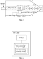
- FIG. 6 is a block diagram of a battery 600 according to an exemplary embodiment.
- the battery 600 includes a cell 610 and a battery protecting component 620.
- the cell 610 is adapted to storing electric energy.
- the battery protecting component 620 is adapted to protecting the cell 610.
- the battery protecting component 620 includes a one-time burning counting unit 621 adapted to forming a count indicating a cycle number of the battery 600.
- a one-time burning counting unit 621 may refer to a counting unit capable of burning one initial numerical value. After the initial numerical value has been burned, each time the battery 600 is charged and discharged for one cycle, the count in the one-time burning counting unit may change and may differ from the initial numerical value. Other than that, the count in the one-time burning counting unit 621 may not be restored to the initial numerical value by being manually modified, re-burnt, etc.
- the one-time burning counting unit 621 may include a down counter.
- the initial numerical value burned in the down counter may indicate the service life of the battery 600.
- a count of the down counter may indicate a difference between the service life of the battery 600 and the cycle number of the battery 600.
- the service life of the battery 600 is the number of times the battery 600 may charge and discharge cyclically.
- the initial numerical value burned in the down counter may be 800.
- the count of the down counter may decrease by 1.
- the cycle number of the battery may be 100.
- the count of the down counter decreases to 0, it may mean that the service life of the battery ends.
- a cycle number of a battery 600 may be a cycle number of a cell 610.
- a one-time burning counting unit 621 may be provided in a battery protecting component 620.
- a cycle number of a battery 600 may be indicated by a count therein. Accordingly, reuse of the battery protecting component 620 is reduced, ensuring that a count in the one-time burning counting unit 621 indicates the accurate cycle number of the battery 600, reducing a probability of secondary use of the battery protecting component 620, improving safety and reliability of the battery 600.
- the battery protecting component 620 may further include an encrypting unit.
- the encrypting unit may be electrically connected to the one-time burning counting unit 621.
- the encrypting unit may be adapted to acquiring the cycle number of the battery 600 and an identification (such as an identification code) of the battery protecting component 620, and encrypting the cycle number of the battery 600 and the identification (such as an identification code) of the battery protecting component 620 using a preset algorithm, generating a first sequence.
- the encrypting unit for example, may include an encrypting circuit.
- the first sequence may be compared to a second sequence generated by electronic equipment using the battery 600 based on a cycle number of a preset cell and an identification of a preset battery protecting component stored in the electronic equipment, to determine whether the battery protecting component 620 meets a second preset matching relation with the electronic equipment.
- the preset battery protecting component meets the second preset matching relation with the electronic equipment.
- An encrypting unit may include a coulomb counter with a preset algorithm, or an IC capable of implementing encryption.
- the preset algorithm may include an encryption algorithm, such as an SHA.
- an encrypting unit is provided in a battery protecting component 620.
- Electronic equipment identifies a battery 600 using the encrypting unit, improving safety in using the battery.
- FIG. 7 is a block diagram of a device 800 for identifying a battery according to an exemplary embodiment.
- the device 800 may be a mobile phone, a computer, digital broadcasting UE, a message transceiver, a game console, tablet equipment, medical equipment, fitness equipment, a personal digital assistant, etc.
- the device 800 may include at least one of a processing component 802, memory 804, a power supply component 806, a multimedia component 808, an audio component 810, an Input / Output (I/O) interface 812, a sensor component 814, or a communication component 816.
- a processing component 802 memory 804
- a power supply component 806 a multimedia component 808, an audio component 810, an Input / Output (I/O) interface 812, a sensor component 814, or a communication component 816.
- I/O Input / Output
- the processing component 802 may generally control an overall operation of the device 800, such as operations associated with display, a telephone call, data communication, a camera operation, a recording operation, etc.
- the processing component 802 may include one or more processors 820 to execute instructions so as to complete all or part of the options of an aforementioned method.
- the processing component 802 may include one or more modules to facilitate interaction between the processing component 802 and other components.
- the processing component 802 may include a multimedia module to facilitate interaction between the multimedia component 808 and the processing component 802.
- the memory 804 may be adapted to storing various types of data to support the operation at the device 800. Examples of such data may include instructions of any application or method adapted to operating on the device 800, contact data, phonebook data, messages, pictures, videos, etc.
- the memory 804 may be actualized by any type of transitory or non-transitory storage equipment or a combination thereof, such as Static Random Access Memory (SRAM), Electrically Erasable Programmable Read-Only Memory (EEPROM), Erasable Programmable Read-Only Memory (EPROM), Programmable Read-Only Memory (PROM), Read-Only Memory (ROM), magnetic memory, flash memory, a magnetic disk, a compact disk, etc.
- SRAM Static Random Access Memory
- EEPROM Electrically Erasable Programmable Read-Only Memory
- EPROM Erasable Programmable Read-Only Memory
- PROM Programmable Read-Only Memory
- ROM Read-Only Memory
- magnetic memory flash memory, a magnetic disk, a compact disk, etc.
- the power supply component 806 may supply electric power to various components of the device 800.
- the power supply component 806 may include a power management system, one or more power sources, and other components related to generating, managing, and distributing electricity for the device 800.
- the multimedia component 808 may include a screen that provides an output interface between the device 800 and a user.
- the screen may include a Liquid Crystal Display (LCD) and a Touch Panel (TP). If the screen may include a TP, the screen may be actualized as a touch screen to receive a signal input by a user.
- the TP may include one or more touch sensors for sensing touch, slide, and gestures on the TP. The one or more touch sensors not only may sense the boundary of a touch or slide move, but also detect the duration and pressure related to the touch or slide move.
- the multimedia component 808 may include at least one of a front camera or a rear camera.
- At least one of the front camera or the rear camera may receive external multimedia data.
- Each of the front camera or the rear camera may be a fixed optical lens system or may have a focal length and be capable of optical zooming.
- the audio component 810 may be adapted to outputting and / or inputting an audio signal.
- the audio component 810 may include a microphone (MIC).
- the MIC may be adapted to receiving an external audio signal.
- the received audio signal may be further stored in the memory 804 or may be sent via the communication component 816.
- the audio component 810 may further include a loudspeaker adapted to outputting the audio signal.
- the I/O interface 812 may provide an interface between the processing component 802 and a peripheral interface module.
- a peripheral interface module may be a keypad, a click wheel, a button, etc.
- a button may include but is not limited to at least one of a homepage button, a volume button, a start button, or a lock button.
- the sensor component 814 may include one or more sensors for assessing various states of the device 800. For example, the sensor component 814 may detect an on/off state of the device 800 and relative location of components such as the display and the keypad of the device 800. The sensor component 814 may further detect a change in the location of the device 800 or of a component of the device 800, whether there is contact between the device 800 and a user, the orientation or acceleration / deceleration of the device 800, a change in the temperature of the device 800, etc.
- the sensor component 814 may include a proximity sensor adapted to detecting existence of a nearby object without physical contact.
- the sensor component 814 may further include an optical sensor such as a Complementary Metal-Oxide-Semiconductor (CMOS) or a Charge-Coupled-Device (CCD) image sensor used in an imaging application.
- CMOS Complementary Metal-Oxide-Semiconductor
- CCD Charge-Coupled-Device
- the sensor component 814 may further include an acceleration sensor, a gyroscope sensor, a magnetic sensor, a pressure sensor, a temperature sensor, etc.
- the communication component 816 may be adapted to facilitating wired or wireless communication between the device 800 and other equipment.
- the device 800 may access a wireless network based on a communication standard such as Wi-Fi, 2G, 3G, ... , or a combination thereof.
- the communication component 816 may broadcast related information or receive a broadcast signal from an external broadcast management system via a broadcast channel.
- the communication component 816 may include a Near Field Communication (NFC) module for short-range communication.
- the NFC module may be based on technology such as Radio Frequency Identification (RFID), Infrared Data Association (IrDA), Ultra-Wideband (UWB) technology, Bluetooth (BT), etc.
- RFID Radio Frequency Identification
- IrDA Infrared Data Association
- UWB Ultra-Wideband
- Bluetooth Bluetooth
- the device 800 may be actualized by one or more electronic components such as an Application Specific Integrated Circuit (ASIC), a Digital Signal Processor (DSP), a Digital Signal Processing Device (DSPD), a Programmable Logic Device (PLD), a Field Programmable Gate Array (FPGA), a controller, a microcontroller, a microprocessor, etc., to implement an aforementioned method.
- ASIC Application Specific Integrated Circuit
- DSP Digital Signal Processor
- DSPD Digital Signal Processing Device
- PLD Programmable Logic Device
- FPGA Field Programmable Gate Array
- a transitory or non-transitory computer-readable storage medium including instructions, such as memory 804 including instructions, may be provided.
- the instructions may be executed by the processor 820 of the device 800 to implement an aforementioned method.
- the computer-readable storage medium may be Read-Only Memory (ROM), Random Access Memory (RAM), Compact Disc Read-Only Memory (CD-ROM), a magnetic tape, a floppy disk, optical data storage equipment, etc.
- a transitory or non-transitory computer-readable storage medium has stored therein instructions which, when executed by a processor of electronic equipment, allow the electronic equipment to execute a method for identifying a battery according to an embodiment herein.
- a term “and / or” may describe an association between associated objects, indicating three possible relationships. For example, by A and / or B, it may mean that there may be three cases, namely, existence of but A, existence of both A and B, or existence of but B.
- a slash mark “/” may generally denote an "or” relationship between two associated objects that come respectively before and after the slash mark. Singulars "a/an”, “said” and “the” are intended to include the plural form, unless expressly illustrated otherwise by context.
Applications Claiming Priority (1)
| Application Number | Priority Date | Filing Date | Title |
|---|---|---|---|
| CN202010499084.3A CN113759259A (zh) | 2020-06-04 | 2020-06-04 | 电池识别方法、识别设备、电池、识别装置及存储介质 |
Publications (1)
| Publication Number | Publication Date |
|---|---|
| EP3920366A1 true EP3920366A1 (fr) | 2021-12-08 |
Family
ID=75277902
Family Applications (1)
| Application Number | Title | Priority Date | Filing Date |
|---|---|---|---|
| EP21165663.2A Pending EP3920366A1 (fr) | 2020-06-04 | 2021-03-29 | Procédé et dispositif d'identification de batterie et batterie |
Country Status (3)
| Country | Link |
|---|---|
| US (1) | US11824378B2 (fr) |
| EP (1) | EP3920366A1 (fr) |
| CN (1) | CN113759259A (fr) |
Families Citing this family (2)
| Publication number | Priority date | Publication date | Assignee | Title |
|---|---|---|---|---|
| WO2023216192A1 (fr) * | 2022-05-12 | 2023-11-16 | 北京小米移动软件有限公司 | Procédé et appareil de détermination d'état de batterie et support de stockage |
| WO2023245356A1 (fr) * | 2022-06-20 | 2023-12-28 | 北京小米移动软件有限公司 | Procédé et appareil de charge pour un dispositif électronique, et dispositif électronique et support de stockage |
Citations (6)
| Publication number | Priority date | Publication date | Assignee | Title |
|---|---|---|---|---|
| EP1065774A2 (fr) * | 1999-06-30 | 2001-01-03 | Research In Motion Limited | Système automatique de détection de batteries et procédé pour détecter une batterie secondaire avec peu de charge résiduelle |
| US20050162172A1 (en) * | 1997-11-03 | 2005-07-28 | Midtronics, Inc. | Wireless battery monitor |
| US20120169271A1 (en) * | 2010-12-30 | 2012-07-05 | The Gillette Company | Single Wire Battery Pack Temperature and Identification Method |
| CN107367699A (zh) * | 2017-09-14 | 2017-11-21 | 南京林业大学 | 一种基于分数阶模型的锂电池soc估算新方法 |
| US20180062401A1 (en) * | 2016-08-24 | 2018-03-01 | The Boeing Company | Detecting internal short circuits in batteries |
| US20200014218A1 (en) * | 2016-04-04 | 2020-01-09 | Qnovo Inc. | User identification from battery characteristics |
Family Cites Families (5)
| Publication number | Priority date | Publication date | Assignee | Title |
|---|---|---|---|---|
| CN103033751B (zh) * | 2011-09-29 | 2015-06-24 | 联想(北京)有限公司 | 一种电池检测方法、电池及电子设备 |
| KR101863092B1 (ko) * | 2011-12-01 | 2018-07-05 | 삼성에스디아이 주식회사 | 배터리 충전 제어 방법, 및 이를 적용한 배터리 팩 |
| CN103605077B (zh) * | 2013-10-25 | 2016-01-13 | 小米科技有限责任公司 | 预定电池识别方法、装置及电子设备 |
| CN104330638B (zh) * | 2014-11-19 | 2017-09-05 | 惠州Tcl移动通信有限公司 | 一种原装充电线的识别方法及系统 |
| CN108363020B (zh) * | 2018-04-03 | 2020-03-06 | 深圳市道通智能航空技术有限公司 | 确定电池状态的方法和装置、芯片、电池及飞行器 |
-
2020
- 2020-06-04 CN CN202010499084.3A patent/CN113759259A/zh active Pending
- 2020-12-18 US US17/127,782 patent/US11824378B2/en active Active
-
2021
- 2021-03-29 EP EP21165663.2A patent/EP3920366A1/fr active Pending
Patent Citations (6)
| Publication number | Priority date | Publication date | Assignee | Title |
|---|---|---|---|---|
| US20050162172A1 (en) * | 1997-11-03 | 2005-07-28 | Midtronics, Inc. | Wireless battery monitor |
| EP1065774A2 (fr) * | 1999-06-30 | 2001-01-03 | Research In Motion Limited | Système automatique de détection de batteries et procédé pour détecter une batterie secondaire avec peu de charge résiduelle |
| US20120169271A1 (en) * | 2010-12-30 | 2012-07-05 | The Gillette Company | Single Wire Battery Pack Temperature and Identification Method |
| US20200014218A1 (en) * | 2016-04-04 | 2020-01-09 | Qnovo Inc. | User identification from battery characteristics |
| US20180062401A1 (en) * | 2016-08-24 | 2018-03-01 | The Boeing Company | Detecting internal short circuits in batteries |
| CN107367699A (zh) * | 2017-09-14 | 2017-11-21 | 南京林业大学 | 一种基于分数阶模型的锂电池soc估算新方法 |
Also Published As
| Publication number | Publication date |
|---|---|
| US11824378B2 (en) | 2023-11-21 |
| US20210384742A1 (en) | 2021-12-09 |
| CN113759259A (zh) | 2021-12-07 |
Similar Documents
| Publication | Publication Date | Title |
|---|---|---|
| CN107843802B (zh) | 内短路检测方法及装置 | |
| EP3813221A1 (fr) | Procédé de chargement de batterie, appareil de chargement de batterie et support d'enregistrement | |
| EP3920366A1 (fr) | Procédé et dispositif d'identification de batterie et batterie | |
| ES2753802T3 (es) | Procedimiento de carga, dispositivo de carga y terminal | |
| CN108091808B (zh) | 电池、设备、充电控制方法及装置 | |
| EP3961848A1 (fr) | Procédé et appareil de commande de charge, dispositif électronique et support de stockage | |
| CN106169798A (zh) | 高压充电系统、高压充电电池及终端设备 | |
| KR102610543B1 (ko) | 전자 장치 및 그의 배터리를 진단하는 방법 | |
| US9197083B2 (en) | Electronic apparatus, control method, and recording medium | |
| JP2011061561A (ja) | 携帯端末装置、該携帯端末装置に用いられる電池管理方法及び電池管理制御プログラム | |
| CN111342506B (zh) | 用于串联电池的充电技术 | |
| CN116859248A (zh) | 电池循环寿命预测方法、装置及存储介质 | |
| JP2002017049A (ja) | 充放電システム | |
| CN113253141B (zh) | 电池电量计量方法、电子设备及存储介质 | |
| CN109066850B (zh) | 电池管理方法和装置 | |
| CN112701737B (zh) | 电池电路、充电方法及装置、电子设备 | |
| CN216904279U (zh) | 一种放电保护电路及电池组件 | |
| CN117665615A (zh) | 电池荷电状态确定方法、确定装置、监测系统及存储介质 | |
| CN108964164B (zh) | 一种充放电电路、方法及便携式电子设备 | |
| CN115001060A (zh) | 电池保护电路、电池组件及终端 | |
| CN117318198A (zh) | 终端的充放电方法、装置、可读存储介质及芯片 | |
| CN113452099A (zh) | 放电方法及装置、电子设备、存储介质 | |
| CN115603394A (zh) | 一种电池电路及其控制方法、装置、终端及存储介质 | |
| CN116632950A (zh) | 电池均衡方法、装置及可读存储介质 | |
| JP5992282B2 (ja) | 電子機器及び制御プログラム並びに電池異常判定方法 |
Legal Events
| Date | Code | Title | Description |
|---|---|---|---|
| PUAI | Public reference made under article 153(3) epc to a published international application that has entered the european phase |
Free format text: ORIGINAL CODE: 0009012 |
|
| STAA | Information on the status of an ep patent application or granted ep patent |
Free format text: STATUS: THE APPLICATION HAS BEEN PUBLISHED |
|
| AK | Designated contracting states |
Kind code of ref document: A1 Designated state(s): AL AT BE BG CH CY CZ DE DK EE ES FI FR GB GR HR HU IE IS IT LI LT LU LV MC MK MT NL NO PL PT RO RS SE SI SK SM TR |
|
| B565 | Issuance of search results under rule 164(2) epc |
Effective date: 20210618 |
|
| STAA | Information on the status of an ep patent application or granted ep patent |
Free format text: STATUS: REQUEST FOR EXAMINATION WAS MADE |
|
| 17P | Request for examination filed |
Effective date: 20220601 |
|
| RBV | Designated contracting states (corrected) |
Designated state(s): AL AT BE BG CH CY CZ DE DK EE ES FI FR GB GR HR HU IE IS IT LI LT LU LV MC MK MT NL NO PL PT RO RS SE SI SK SM TR |