EP1065774A2 - Système automatique de détection de batteries et procédé pour détecter une batterie secondaire avec peu de charge résiduelle - Google Patents
Système automatique de détection de batteries et procédé pour détecter une batterie secondaire avec peu de charge résiduelle Download PDFInfo
- Publication number
- EP1065774A2 EP1065774A2 EP00113308A EP00113308A EP1065774A2 EP 1065774 A2 EP1065774 A2 EP 1065774A2 EP 00113308 A EP00113308 A EP 00113308A EP 00113308 A EP00113308 A EP 00113308A EP 1065774 A2 EP1065774 A2 EP 1065774A2
- Authority
- EP
- European Patent Office
- Prior art keywords
- power source
- test
- controller
- battery
- source voltage
- Prior art date
- Legal status (The legal status is an assumption and is not a legal conclusion. Google has not performed a legal analysis and makes no representation as to the accuracy of the status listed.)
- Granted
Links
Images


Classifications
-
- H—ELECTRICITY
- H02—GENERATION; CONVERSION OR DISTRIBUTION OF ELECTRIC POWER
- H02J—CIRCUIT ARRANGEMENTS OR SYSTEMS FOR SUPPLYING OR DISTRIBUTING ELECTRIC POWER; SYSTEMS FOR STORING ELECTRIC ENERGY
- H02J7/00—Circuit arrangements for charging or depolarising batteries or for supplying loads from batteries
- H02J7/0029—Circuit arrangements for charging or depolarising batteries or for supplying loads from batteries with safety or protection devices or circuits
- H02J7/0031—Circuit arrangements for charging or depolarising batteries or for supplying loads from batteries with safety or protection devices or circuits using battery or load disconnect circuits
-
- H—ELECTRICITY
- H02—GENERATION; CONVERSION OR DISTRIBUTION OF ELECTRIC POWER
- H02J—CIRCUIT ARRANGEMENTS OR SYSTEMS FOR SUPPLYING OR DISTRIBUTING ELECTRIC POWER; SYSTEMS FOR STORING ELECTRIC ENERGY
- H02J7/00—Circuit arrangements for charging or depolarising batteries or for supplying loads from batteries
- H02J7/00032—Circuit arrangements for charging or depolarising batteries or for supplying loads from batteries characterised by data exchange
- H02J7/00038—Circuit arrangements for charging or depolarising batteries or for supplying loads from batteries characterised by data exchange using passive battery identification means, e.g. resistors or capacitors
- H02J7/00041—Circuit arrangements for charging or depolarising batteries or for supplying loads from batteries characterised by data exchange using passive battery identification means, e.g. resistors or capacitors in response to measured battery parameters, e.g. voltage, current or temperature profile
-
- H—ELECTRICITY
- H02—GENERATION; CONVERSION OR DISTRIBUTION OF ELECTRIC POWER
- H02J—CIRCUIT ARRANGEMENTS OR SYSTEMS FOR SUPPLYING OR DISTRIBUTING ELECTRIC POWER; SYSTEMS FOR STORING ELECTRIC ENERGY
- H02J7/00—Circuit arrangements for charging or depolarising batteries or for supplying loads from batteries
- H02J7/00047—Circuit arrangements for charging or depolarising batteries or for supplying loads from batteries with provisions for charging different types of batteries
Definitions
- the present invention relates to a system and method for testing a battery to determine if it is a rechargeable battery. More specifically, the present invention relates to an automatic battery detection system and method for use with an electronic device, such as wireless two-way communication devices, pagers, integrated email devices and cellular phones, powered by a battery. The electronic device is placed in an associated charging cradle to test the battery. This testing is performed by a controller in the charging cradle that determines if the battery includes a rechargeable cell and, if it does, if the rechargeable cell needs to be recharged.
- an electronic device such as wireless two-way communication devices, pagers, integrated email devices and cellular phones, powered by a battery.
- the electronic device is placed in an associated charging cradle to test the battery. This testing is performed by a controller in the charging cradle that determines if the battery includes a rechargeable cell and, if it does, if the rechargeable cell needs to be recharged.
- wireless transceivers such as those used in radios, cell phones, pagers, etc.
- rechargeable batteries Most commercially available rechargeable cells, such as Nickel Metal Hydride (NiMH) or Nickel-Cadmium (NiCd) cells, are recharged by an external charger (i.e. , the user removes the batteries from the device and recharges them in the external charger). However, some devices recharge the batteries without removing them from the device.
- NiMH Nickel Metal Hydride
- NiCd Nickel-Cadmium
- the type of cell within the battery must first be determined by the device.
- the rechargeable batteries are modified to facilitate cell-type detection. This modification of the battery typically is done by adding a third terminal to the battery where detection is performed by a detector that measures the batteries characteristics through an electrical contact with the third terminal.
- Another method of in-unit cell detection is performed through some form of user input such as a mechanical switch with an arrow that is lined up with one or more markings on the device. These markings represent chemical symbols or words that indicate the cell-type of the battery to the device charging the cell.
- a charging cradle receives an electronic device powered by a battery.
- a controller performs a method of internal-device battery cell detection, i.e. , distinguishing between NiMH/NiCd and other types of cells in the battery, before recharging the battery.
- a method determines the cell chemistry without any modifications to the battery and/or without any user input by performing a plurality of tests.
- the tests may include a Battery Voltage Test, an Internal Resistance (IR) Test, and a Timed Voltage Test.
- the tests are preferably executed in a predetermined order. The testing is performed through a combination of hardware and software in the charging cradle.
- One advantage of the present invention is that alkaline, lithium, rechargeable alkaline, and carbon-zinc cells are detected and not recharged while the battery remains in the device without modifying the battery, which protects the device from being damaged.
- Another advantage of the present invention is that damaged NiMH and NiCd cells are detected and not recharged while the battery remains in the device without modifying the battery, which protects the device from being damaged.
- Still another advantage of the present invention is that close to fully charged NiMH and NiCd cells are detected and not recharged while the battery remains in the device without modifying the battery, which extends the life of the battery and prevents overcharging of the battery.
- Another advantage of the present invention is that the detection process may be conducted without requiring input from a user.
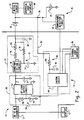
- the apparatus 10 includes an external power source adapter 12, preferably an AC adapter, a holder 14 (or charging cradle), and an electronic device 16.
- the device 16 is preferably an Inter@ctiveTM Pager 850, which is manufactured by Research In Motion Limited (RIM), and the holder 14 is preferably an Inter@ctive TM Pager 850 Charging Cradle, which is also manufactured by RIM for use with the pager 16.
- RIM Research In Motion Limited
- the holder 14 preferably includes a DC-DC converter 18, a switch block 20, a constant current source 22, a controller 24, and an external user interface 26.
- the converter 18 is preferably a 12V to 5V converter, which converts voltage received from the adapter 12 and sends the converted voltage to the switch block 20. Electricity flowing through the switch block 20 to the constant current source 22 is controlled by the controller 24.
- the device 16 preferably includes a battery 28, a Schottky diode 30, a device circuit 32, and a temperature detection circuit 34.
- the constant current source 22 in the holder 14 is protected from reverse current since the diode 30 only permits current flow into the electronic device 16.
- the controller 24 performs tests on the battery 28 by reading the voltage at node 36 of the device 16 to determine if the battery 28 contains rechargeable NiMH or NiCd cells that need to be recharged.
- the battery 28 is recharged by the constant current source 22 when the controller 24 determines that the battery 28 is a rechargeable battery that is in need of recharging.
- the controller 24 monitors other parameters of the electronic device 16, such as temperature, through a temperature detection circuit 34.
- the device circuit 32 is preferably configured to operate as a wireless transceiver, such as a two way paging computer, a portable electronic messaging device, or a hand held e-mail client.
- a wireless transceiver such as a two way paging computer, a portable electronic messaging device, or a hand held e-mail client.
- An example of such a device is set forth in co-pending Canadian Patent Application No. 2,276,697, titled "Hand-Held Electronic Device With a Keyboard Optimized for Use With The Thumbs", filed 28 June 1999 and assigned to the assignee of the present application. Although this is the preferred device circuit 32, other types of circuits could be utilized in the present invention.
- the external interface 26 of the holder 14 is preferably either a light-emitting diode (LED) or a graphical unit interface (GUI) that alerts a user of the device 16 the status of the testing being performed. For example, an LED illuminates continuously during the detecting. Then, if the controller 24 determines the battery 28 contains NiCd or NiMH cells that need to be recharged, the LED blinks until a recharging cycle is completed at which time the LED is illuminated continuously again.
- the external interface 26 made be located on the holder 14 or a be a computer monitor (not shown) that is coupled to the holder 14. Further, the information can alternatively be displayed on a GUI 38 of the pager 16.
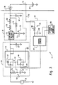
- the switching block 20 controls the flow of current from the converter 18 to the constant current source 22 by only allowing current to pass through it when it is turned ON by the controller 24. This occurs when the controller 24 determines the battery 28 needs to be recharged. Further, when current flows through switch block 20 it acts as a level shifting switch.
- the switch block 20 includes a low pass filter 50, a NP load switch circuit 52, and a filtering capacitor 54.
- the low pass filter 50 which includes resistor 56 and capacitor 58, filters the power from the converter 18.
- the low pass filter 50 includes a 100 k ⁇ resistor 56 and a 1000 pF capacitor 58, and the value of the filtering capacitor 54 is 1 uF capacitor.
- a preferable circuit for the NP load switch circuit 52 is shown, which is a FCD6363L connection circuit manufactured by Fairchild Semiconductor Corporation.
- This connection circuit 52 includes a p-channel, high current MOSFET 60 with a diode 62 connected drain to source across the FET 60 and an n-channel, low current MOSFET 64 with a diode 66 connected source to drain across the FET 64.
- the MOSFET 60 acts as a switch.
- the MOSFET 64 is configured as a level shifting switch that is switched to an ON state by the controller 24 by biasing the gate of the MOSFET 64. This allows a 5 volt processor to control a 12 volt signal.
- MOSFET 64 based on the ON state of MOSFET 64, the gate of MOSFET 60 is biased, switching it to an ON state. In the ON state, the MOSFET 60 allows electricity to flow through the switch block 20 to the constant current source 22 via the filtering capacitor 54.
- the constant current source 22 includes a constant voltage circuit 70 and a low pass filter 72.
- a capacitor 74 and a resistor 76 make up the low pass filter 72.
- the constant current source 22 further includes a resistor 78 across which there is a constant voltage from the constant voltage circuit 70 such that the constant voltage is converted into the constant current.
- This constant current flows into the electronic device 16.
- the constant current source 22 only conducts when switch block 20 is turned on by the controller 24 during a recharging operation of battery 28.
- the constant voltage circuit 70 is a EZ1117CM circuit manufactured by Semtech Corporation.
- the value of capacitor 74 is 0.1 uF
- the value of resistor 76 is 383 ⁇
- the value of resistor 78 is 2 ⁇
- the value of capacitor 82 is 10 uF.
- the controller 24 includes a control circuit 84 and a low pass filter 86.
- the low pass filter 86 which includes a resistor 88 and a capacitor 90, filters signals flowing through a coupling element 92 between the node 36 and the control circuit 84.
- the control circuit 84 is a PIC16C711 control chip manufactured by Microchip Technology, Inc.
- the value of resistor 88 is 10 k ⁇
- the value of capacitor 90 is 6800 pF.
- the controller 24 determines what type of cells are contained in the battery 28 without any previous knowledge of the cell-type. The determination is made when the device 16 is properly inserted into the holder 14. Once proper insertion is detected, the controller 24 starts testing of the battery 28. If the testing is successful, i.e ., the battery 28 is rechargeable and in need of recharging, the controller 24 turns ON ??? through switch block 20 which permits current flow from the converter 18 to the constant current source 22. The current then passes through the constant current source 22 into the device 16 to recharge the battery 28.
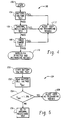
- Figure 4 sets forth a preferred method 100 of cell detection performed by the controller 24, which allows for differentiation between NiMH/NiCd cells and other cells.
- the controller 24 detects and does not recharge an alkaline, lithium, rechargeable alkaline, and carbon-zinc cells, damaged NiMH and NiCd cells, and close to fully charged NiMH and NiCd cells.
- a plurality of tests are preferably performed by the controller 24 to determine the presence of a "good" NiMH or NiCd cell in the battery 28.
- Three of the plurality of tests include a Battery Voltage Test 104, an Internal Resistance (IR) Test 106, and a Timed Charge Test 108.
- these tests 104-108 should be passed in a predetermined order, although alternatively they could be configured to operate in a different order. If any of the three tests 104-108 fail, then at step 112 a user is alerted, via the external interface 26, that the recharging operation is being terminated.
- These tests 104-108 are described in more detail below with reference to Figures 5-7.
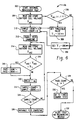
- FIG. 5 sets forth the preferred Battery Voltage Test method 104.
- the Battery Voltage Test 104 is started at step 200.
- the controller 24 reads the voltage V BAT of the battery 28 at node 36 through the coupling element 92. Then, at step 204, the controller 24 determines if the voltage V BAT is below a certain threshold value, preferably 1.396 V. If the voltage V BAT is below the threshold value, then the Battery Voltage Test 104 test was successful and the method 100 proceeds to the IR Test 106 at step 206. If the voltage V BAT is equal to or above the threshold value, then the user is alerted, via the external interface 26, that the recharging operation is being terminated to ensure there is no damage to the battery 28 or the device 16.
- a certain threshold value preferably 1.396 V.
- the controller 84 reads the battery voltage 16 times.
- the purpose of sampling the voltage 16 times is to remove any random (or white) noise that could be seen on the coupling element 92.
- the 16 samples are then averaged as V BAT and compared to the threshold voltage of 1.396 V.
- the reason for performing the Battery Voltage Test 104 is because most fully charged alkaline and lithium AA cells have voltages above the specified threshold. Further, most fully charged NiMH and NiCd cells have a terminal voltage in the neighbourhood of the threshold voltage. Therefore, the Battery Voltage Test 104 detects both fully charged NiMH and NiCd cells (to prevent overcharging) and non-rechargeable cells.
- FIG. 6 sets forth the preferred steps of the IR Test 106.
- the IR Test 106 determines the internal resistance of the battery 28 inside the device 16 to determine the cell-type.
- the NiMH and NiCd cells have a low internal resistance (due to their construction) such that their lower IRs allow them to be differentiated by this test.
- the values, V AA1 and V AA2 are measured by determining the pulse height voltage response to a 20 ms pulse of known current from the constant current source.
- the voltages, V AA1 and V AA2 are proportional to the internal resistance of the battery and are used directly as a measure of the battery's internal resistance.
- the IR Test 106 is performed by the controller 24 as follows. Once the Battery Voltage Test 104 has passed, at step 302 the IR Test 106 is started. A first voltage V AA1 of the battery 28 is read and stored at step 304. Then, at step 306 the first voltage V AA1 is compared to a predetermined voltage value, preferably 1.1 V. Based on this comparison, at step 308 a threshold voltage value V T is determined and set so that it is used during testing. Preferably, the threshold voltage V T is set at 137 mV if V AA1 is equal to or greater than 1.1 v or V T is set at 200 mV if V AA1 is less than 1.1 V.
- a sample-count value and a pass-count value are both set to 0 at step 310.
- the controller 24 enables test charging of the battery 28, preferably at a rate of 630 mA for 20 ms.
- a second voltage value V AA2 is stored at step 314. This second value V AA2 is then subtracted from the first value V AA1 to determined a difference value that is then compared to the threshold voltage V T at step 316.
- the pass-count value is incremented to pass-count +1 at step 318, (2) the testing is delayed a predetermined time period at step 320, which is preferably 1 ms, and (3) the sample-count value is incremented to sample-count +1 at step 322. Otherwise, if the difference V AA1 - V AA2 is equal to or above the threshold voltage V T , then only steps 320 and 322 are performed and the pass-count value step 318 is by-passed.
- the controller 24 determines whether or not 20 voltage samples V AA2 have been read, stored, and used to calculate the difference value for the comparison to the threshold value. If it is determined that there have been less than 20 samples, steps 314-324 are repeated until the sample-count is equal to 20. Otherwise, if it is determined that 20 samples have been taken, then the test charging is disabled at step 326. After disabling the test charging at step 326, a determination is made at step 328 if the pass-count value is greater then or equal to 14, i.e ., at least 14 times during the 20 samples the voltage difference V AA1 - V AA2 was less than the threshold voltage V T at step 316.
- the method 100 proceeds to the Timed Charge Test 108 at step 330. Otherwise, if the pass-count value is less than 14, then the user is alerted at step 332, via the external interface 26, that the recharging operation is being terminated.
- the threshold voltage V T of 137 mV was chosen because most healthy NiMH and NiCd AA cells have a jump in their terminal voltage, during the 20 ms charge, of less than 137 mV. The NiMH and NiCd cells that do not fall below this value are usually damaged cells. Also, the threshold voltage V T of 200 mV was chosen because as cell voltage decreases, the internal resistance of the AA cell rises and this must be taken into account. Further, the predetermined pass-count value of 14 was used because a non-insignificant noise floor is seen at the input pin to an A/D converter (not shown) in the control circuit 84. Therefore, having 14 sample results (of the subtraction) is required to accurately track the shape of the pulse created by charging for 20 ms.
- FIG. 7 sets forth the preferred steps of the Timed Charge Test 108.
- the method 100 proceeds to the Timed Charge Test 108 at step 402 once the battery 28 has passed the Battery Voltage Test 104 and the IR Test 106.
- a sample-count value is set to 0.
- test charging of the battery 28 is enabled at step 406.
- the controller 24 enables charging (at a rate of 630 mA) into the cells within the battery 28 for a period of five seconds. During this period of time, the controller 24 measures the voltage of battery 28 at node 30 in 17 equally time-spaced sets of 16 samples per set, which are then averaged as V BAT at step 408.
- V BAT it is determined if V BAT is above a predetermined threshold value, preferably 1.553 V.
- V BAT is above this threshold value, then the test charging is disabled at step 412. If this occurs, the user is alerted at step 414, via the external user interface 26, that the recharging operation is being terminated. Otherwise, if the V BAT is below the threshold value, the Timed Charge Test 108 is delayed a predetermined time period, preferably 0.3 seconds, at step 416, and then the sample-count value is increased by 1 to sample-count + 1 at step 418.
- the sample-count value is compared to a predetermined sample-count value at step 420, where the predetermined sample-count value is preferably 17. If the sample-count value is less than 17, then steps 408-418 are repeated until the sample-count is equal to 17. Otherwise, the test charging is disabled at step 422, and at step 424 the cell inside the battery 28 is considered to be a NiMH or NiCd cell in need of recharging. If this is determined at step 424, the controller 24 will bias the gate of the MOSFET 64 so that it is in an ON state allowing electricity to flow through MOSFET 64 and the constant current source 22 to the device 16 to begin recharging the battery 28.
- the value of 1.553 V as the threshold level for the V BAT comparison is used because most NiCd and NiMH AA cells, when charged for five seconds at a rate of 630 mA, have terminal voltages that rise to less than 1.553 V. However, NiMH and NiCd cells that are not ready to be recharged have terminal voltages that are above 1.553 V. Thus this test 108, according to a preferred embodiment of the present invention, detects and does not recharge NiMH or NiCd cells that are close to fully charged.
- the Timed Charge Test 108 detects and does not recharge any non-NiMH and non-NiCd AA cells 28 that may have passed the previous two tests 104 and 106.
Priority Applications (1)
| Application Number | Priority Date | Filing Date | Title |
|---|---|---|---|
| EP08168119A EP2037554A1 (fr) | 1999-06-30 | 2000-06-22 | Système automatique de détection de batteries et procédé pour détecter une batterie secondaire avec peu de charge résiduelle |
Applications Claiming Priority (2)
| Application Number | Priority Date | Filing Date | Title |
|---|---|---|---|
| US09/343,304 US6191551B1 (en) | 1999-06-30 | 1999-06-30 | Automatic battery detection system and method for detecting a rechargeable battery with low remaining charge |
| US343304 | 1999-06-30 |
Related Child Applications (1)
| Application Number | Title | Priority Date | Filing Date |
|---|---|---|---|
| EP08168119A Division EP2037554A1 (fr) | 1999-06-30 | 2000-06-22 | Système automatique de détection de batteries et procédé pour détecter une batterie secondaire avec peu de charge résiduelle |
Publications (3)
| Publication Number | Publication Date |
|---|---|
| EP1065774A2 true EP1065774A2 (fr) | 2001-01-03 |
| EP1065774A3 EP1065774A3 (fr) | 2003-08-06 |
| EP1065774B1 EP1065774B1 (fr) | 2008-12-17 |
Family
ID=23345539
Family Applications (2)
| Application Number | Title | Priority Date | Filing Date |
|---|---|---|---|
| EP00113308A Expired - Lifetime EP1065774B1 (fr) | 1999-06-30 | 2000-06-22 | Système automatique de détection de batteries et procédé pour détecter une batterie secondaire avec peu de charge résiduelle |
| EP08168119A Ceased EP2037554A1 (fr) | 1999-06-30 | 2000-06-22 | Système automatique de détection de batteries et procédé pour détecter une batterie secondaire avec peu de charge résiduelle |
Family Applications After (1)
| Application Number | Title | Priority Date | Filing Date |
|---|---|---|---|
| EP08168119A Ceased EP2037554A1 (fr) | 1999-06-30 | 2000-06-22 | Système automatique de détection de batteries et procédé pour détecter une batterie secondaire avec peu de charge résiduelle |
Country Status (5)
| Country | Link |
|---|---|
| US (1) | US6191551B1 (fr) |
| EP (2) | EP1065774B1 (fr) |
| AT (1) | ATE418172T1 (fr) |
| CA (1) | CA2312354C (fr) |
| DE (1) | DE60041104D1 (fr) |
Cited By (3)
| Publication number | Priority date | Publication date | Assignee | Title |
|---|---|---|---|---|
| EP1300920A1 (fr) * | 2001-10-08 | 2003-04-09 | Thomson Licensing S.A. | Dispositif et procédé d'identification de type de batterie électrique |
| WO2017207650A1 (fr) * | 2016-05-31 | 2017-12-07 | Berghof Automation GmbH | Appareil de test de batterie à impulsion de courant continu et procédé de reconnaissance d'un type de batterie |
| EP3920366A1 (fr) * | 2020-06-04 | 2021-12-08 | Beijing Xiaomi Mobile Software Co., Ltd. | Procédé et dispositif d'identification de batterie et batterie |
Families Citing this family (34)
| Publication number | Priority date | Publication date | Assignee | Title |
|---|---|---|---|---|
| US7705828B2 (en) | 1998-06-26 | 2010-04-27 | Research In Motion Limited | Dual-mode mobile communication device |
| US6278442B1 (en) | 1998-06-26 | 2001-08-21 | Research In Motion Limited | Hand-held electronic device with a keyboard optimized for use with the thumbs |
| US6489950B1 (en) | 1998-06-26 | 2002-12-03 | Research In Motion Limited | Hand-held electronic device with auxiliary input device |
| US6380711B2 (en) * | 1999-06-30 | 2002-04-30 | Research In Motion Limited | Battery recharging device and method and an automatic battery detection system and method therefor |
| US6490434B1 (en) * | 1999-08-31 | 2002-12-03 | Agere Systems, Inc. | Systems and methods for completing diagnostic tests on rechargeable devices using cradle contacts |
| US7107160B2 (en) * | 2001-10-09 | 2006-09-12 | Hewlett-Packard Development Company, L.P. | Use-adaptive fuel gauging for battery powered electronic devices |
| US7012402B2 (en) | 2002-02-04 | 2006-03-14 | Sabine, Inc. | Battery charging control |
| US7672798B2 (en) * | 2002-06-27 | 2010-03-02 | Spx Corporation | Apparatus and method for determining the temperature of a charging power source |
| US6842707B2 (en) * | 2002-06-27 | 2005-01-11 | Spx Corporation | Apparatus and method for testing and charging a power source with ethernet |
| US7148657B2 (en) * | 2002-06-27 | 2006-12-12 | Spx Corporation | Apparatus and method for regulating and monitoring a chargeable device with minimal operator intervention |
| US7472820B2 (en) * | 2002-09-06 | 2009-01-06 | Spx Corporation | Code reading apparatus and method |
| CA2427369A1 (fr) * | 2002-12-24 | 2004-06-24 | Research In Motion Limited | Methodes et appareils permettant de commander l'alimentation des circuits electriques d'un appareil de communications sans fil dote d'une interface de module d'identite d'abonne (sim) |
| JP2005204437A (ja) * | 2004-01-16 | 2005-07-28 | Sony Corp | 制御回路装置 |
| US7622895B1 (en) * | 2006-03-23 | 2009-11-24 | Griffin Technology, Inc. | Power level display calibration device |
| US8050657B2 (en) * | 2006-03-28 | 2011-11-01 | Texas Instruments Incorporated | Tamper resistant circuitry and portable electronic devices |
| CN1933277B (zh) * | 2006-09-25 | 2010-05-12 | 惠州市蓝微电子有限公司 | 一种充电器对电池种类的识别方法及其充电器电路 |
| US8803472B2 (en) * | 2007-07-28 | 2014-08-12 | Hewlett-Packard Development Company, L.P. | Safety circuit for charging devices |
| US20090192726A1 (en) * | 2008-01-25 | 2009-07-30 | Eveready Battery Company, Inc. | Electrochemical Composition Detection Device and Method Thereof |
| US8115492B2 (en) * | 2008-01-25 | 2012-02-14 | Eveready Battery Company, Inc. | Fuel gauging system and method thereof |
| US9520743B2 (en) | 2008-03-27 | 2016-12-13 | Echostar Technologies L.L.C. | Reduction of power consumption in remote control electronics |
| US8082455B2 (en) * | 2008-03-27 | 2011-12-20 | Echostar Technologies L.L.C. | Systems and methods for controlling the power state of remote control electronics |
| US8222868B2 (en) * | 2008-04-02 | 2012-07-17 | Techtronic Power Tools Technology Limited | Battery tester for rechargeable power tool batteries |
| US8009054B2 (en) | 2008-04-16 | 2011-08-30 | Echostar Technologies L.L.C. | Systems, methods and apparatus for adjusting a low battery detection threshold of a remote control |
| US7907060B2 (en) * | 2008-05-08 | 2011-03-15 | Echostar Technologies L.L.C. | Systems, methods and apparatus for detecting replacement of a battery in a remote control |
| US20090303097A1 (en) * | 2008-06-09 | 2009-12-10 | Echostar Technologies Llc | Systems, methods and apparatus for changing an operational mode of a remote control |
| US8305249B2 (en) | 2008-07-18 | 2012-11-06 | EchoStar Technologies, L.L.C. | Systems and methods for controlling power consumption in electronic devices |
| US9094723B2 (en) * | 2008-12-16 | 2015-07-28 | Echostar Technologies L.L.C. | Systems and methods for a remote alarm |
| US9257034B2 (en) | 2009-02-19 | 2016-02-09 | Echostar Technologies L.L.C. | Systems, methods and apparatus for providing an audio indicator via a remote control |
| US8134475B2 (en) * | 2009-03-16 | 2012-03-13 | Echostar Technologies L.L.C. | Backlighting remote controls |
| US8339246B2 (en) | 2009-12-30 | 2012-12-25 | Echostar Technologies Llc | Systems, methods and apparatus for locating a lost remote control |
| TW201237758A (en) * | 2011-03-15 | 2012-09-16 | Askey Computer Corp | Lithium cell simulating device |
| US9806547B2 (en) | 2011-09-29 | 2017-10-31 | Texas Instruments Incorporated | Circuits, devices, methods and systems to secure power-up for battery operating devices even with low current chargers and to execute other performances |
| US10038948B2 (en) * | 2014-05-21 | 2018-07-31 | Revo Labs | Battery charging adaptor for a wireless microphone |
| CN112444599B (zh) * | 2019-08-28 | 2023-09-19 | 北京小米移动软件有限公司 | 电池破损检测方法及装置 |
Citations (6)
| Publication number | Priority date | Publication date | Assignee | Title |
|---|---|---|---|---|
| EP0611106A1 (fr) * | 1993-02-11 | 1994-08-17 | Hewlett-Packard Company | Procédé et appareil pour la différentiation des types de piles |
| US5345163A (en) * | 1991-06-05 | 1994-09-06 | Battery Master Inc. | Battery monitoring system |
| EP0673103A1 (fr) * | 1994-03-15 | 1995-09-20 | Ericsson Inc. | Boîtier à piles rechargeable avec circuit d'identification, horloge en temps réel et capacité d'authentification |
| US5587924A (en) * | 1995-03-31 | 1996-12-24 | Compaq Computer Corporation | Automatic system for handling batteries |
| US5729115A (en) * | 1996-06-11 | 1998-03-17 | Ericsson Inc. | Apparatus and method for identifying and charging batteries of different types |
| US5850134A (en) * | 1997-01-06 | 1998-12-15 | Samsung Electronics Co., Ltd. | Battery-powered equipment automatically detecting battery types |
Family Cites Families (4)
| Publication number | Priority date | Publication date | Assignee | Title |
|---|---|---|---|---|
| JPH0799384B2 (ja) * | 1988-09-13 | 1995-10-25 | 日本電気株式会社 | 電池残量表示装置 |
| JPH06164469A (ja) * | 1992-11-25 | 1994-06-10 | Fujitsu Ltd | オンフック/オフフック検出手段及び電池識別手段を備えた携帯端末装置用充電器 |
| US6011843A (en) * | 1996-07-10 | 2000-01-04 | Harris Corporation | Method and apparatus for initiating parallel connections to identified plural sites |
| CA2276697C (fr) | 1998-06-29 | 2003-11-04 | Jason T. Griffin | Appareil electronique portatif avec clavier a utilisation optimale des pouces |
-
1999
- 1999-06-30 US US09/343,304 patent/US6191551B1/en not_active Expired - Lifetime
-
2000
- 2000-06-21 CA CA002312354A patent/CA2312354C/fr not_active Expired - Lifetime
- 2000-06-22 EP EP00113308A patent/EP1065774B1/fr not_active Expired - Lifetime
- 2000-06-22 EP EP08168119A patent/EP2037554A1/fr not_active Ceased
- 2000-06-22 DE DE60041104T patent/DE60041104D1/de not_active Expired - Lifetime
- 2000-06-22 AT AT00113308T patent/ATE418172T1/de not_active IP Right Cessation
Patent Citations (6)
| Publication number | Priority date | Publication date | Assignee | Title |
|---|---|---|---|---|
| US5345163A (en) * | 1991-06-05 | 1994-09-06 | Battery Master Inc. | Battery monitoring system |
| EP0611106A1 (fr) * | 1993-02-11 | 1994-08-17 | Hewlett-Packard Company | Procédé et appareil pour la différentiation des types de piles |
| EP0673103A1 (fr) * | 1994-03-15 | 1995-09-20 | Ericsson Inc. | Boîtier à piles rechargeable avec circuit d'identification, horloge en temps réel et capacité d'authentification |
| US5587924A (en) * | 1995-03-31 | 1996-12-24 | Compaq Computer Corporation | Automatic system for handling batteries |
| US5729115A (en) * | 1996-06-11 | 1998-03-17 | Ericsson Inc. | Apparatus and method for identifying and charging batteries of different types |
| US5850134A (en) * | 1997-01-06 | 1998-12-15 | Samsung Electronics Co., Ltd. | Battery-powered equipment automatically detecting battery types |
Non-Patent Citations (2)
| Title |
|---|
| "METHOD FOR DETERMINING BATTERY TYPE AND REMAINING BATTERY LIFE" IBM TECHNICAL DISCLOSURE BULLETIN, IBM CORP. NEW YORK, US, vol. 40, no. 4, 1 April 1997 (1997-04-01), pages 191-193, XP000728309 ISSN: 0018-8689 * |
| CATES R, RICHEY R: "PIC16C71A based battery charger for NiCD and NiMH batteries" , PENTON PUBLISHING , USA XP001152798 Proceedings of the Third Annual Portable by Design Conference, Santa Clara, CA, USA, 25-29 March 1996, pages 193-199 * |
Cited By (5)
| Publication number | Priority date | Publication date | Assignee | Title |
|---|---|---|---|---|
| EP1300920A1 (fr) * | 2001-10-08 | 2003-04-09 | Thomson Licensing S.A. | Dispositif et procédé d'identification de type de batterie électrique |
| WO2017207650A1 (fr) * | 2016-05-31 | 2017-12-07 | Berghof Automation GmbH | Appareil de test de batterie à impulsion de courant continu et procédé de reconnaissance d'un type de batterie |
| US11043704B2 (en) | 2016-05-31 | 2021-06-22 | Berghof Automation GmbH | DC pulse battery testing device and method for determining a battery type |
| EP3920366A1 (fr) * | 2020-06-04 | 2021-12-08 | Beijing Xiaomi Mobile Software Co., Ltd. | Procédé et dispositif d'identification de batterie et batterie |
| US11824378B2 (en) | 2020-06-04 | 2023-11-21 | Beijing Xiaomi Mobile Software Co., Ltd. | Method and device for identifying battery, battery, and storage medium |
Also Published As
| Publication number | Publication date |
|---|---|
| CA2312354A1 (fr) | 2000-12-30 |
| EP2037554A1 (fr) | 2009-03-18 |
| EP1065774A3 (fr) | 2003-08-06 |
| CA2312354C (fr) | 2003-02-18 |
| DE60041104D1 (de) | 2009-01-29 |
| EP1065774B1 (fr) | 2008-12-17 |
| ATE418172T1 (de) | 2009-01-15 |
| US6191551B1 (en) | 2001-02-20 |
Similar Documents
| Publication | Publication Date | Title |
|---|---|---|
| US6380711B2 (en) | Battery recharging device and method and an automatic battery detection system and method therefor | |
| EP1065774B1 (fr) | Système automatique de détection de batteries et procédé pour détecter une batterie secondaire avec peu de charge résiduelle | |
| US8639954B2 (en) | Portable electronic device and method for recovering power to a rechargeable battery used therein | |
| JP3766491B2 (ja) | バッテリ電力が供給されるシステム | |
| US6504344B1 (en) | Monitoring battery packs | |
| US6897635B2 (en) | Method for predicting remaining charge of portable electronics battery | |
| US7078879B2 (en) | Method and apparatus for testing and charging a power source | |
| US6747436B2 (en) | Method and apparatus for identifying and charging different types of batteries | |
| US6479962B2 (en) | In-device charging system and method for multi-chemistry battery systems | |
| US7259538B2 (en) | Adaptive battery conditioning employing battery chemistry determination | |
| EP1895312A1 (fr) | Dispositif de contrôle de batterie, procédé de contrôle de batterie, dispositif de source d'alimentation et appareil électronique | |
| JP2008136278A (ja) | 充電器 | |
| IE901029L (en) | Method and apparatus for determining battery type and¹modifying operating characteristics | |
| US7693671B2 (en) | Battery control device, battery control method, battery pack, electronic apparatus and control circuit for calculating charging-discharging count of battery | |
| EP0902522B1 (fr) | Méthode de controle de charge et chargeur pour une batterie rechargeable | |
| JP2006318682A (ja) | 充電器 | |
| JP2008277136A (ja) | 電池パック、電池回路、及び充電システム | |
| EP0966090A2 (fr) | Méthode et appareil pour charger des batteries | |
| US7012402B2 (en) | Battery charging control | |
| JP2007110820A (ja) | パック電池 | |
| US7911531B2 (en) | Battery, camera and camera system | |
| JP3637758B2 (ja) | 電池の充電法 | |
| CN101252284A (zh) | 半导体装置和充电式电源装置 | |
| JP3104747U (ja) | 太陽電池式充電装置 | |
| US5600224A (en) | Apparatus and method for charging only rechargeable batteries |
Legal Events
| Date | Code | Title | Description |
|---|---|---|---|
| PUAI | Public reference made under article 153(3) epc to a published international application that has entered the european phase |
Free format text: ORIGINAL CODE: 0009012 |
|
| 17P | Request for examination filed |
Effective date: 20000622 |
|
| AK | Designated contracting states |
Kind code of ref document: A2 Designated state(s): AT BE CH CY DE DK ES FI FR GB GR IE IT LI LU MC NL PT SE |
|
| AX | Request for extension of the european patent |
Free format text: AL;LT;LV;MK;RO;SI |
|
| PUAL | Search report despatched |
Free format text: ORIGINAL CODE: 0009013 |
|
| AK | Designated contracting states |
Designated state(s): AT BE CH CY DE DK ES FI FR GB GR IE IT LI LU MC NL PT SE |
|
| AX | Request for extension of the european patent |
Extension state: AL LT LV MK RO SI |
|
| 17Q | First examination report despatched |
Effective date: 20040310 |
|
| AKX | Designation fees paid |
Designated state(s): AT BE CH CY DE DK ES FI FR GB GR IE IT LI LU MC NL PT SE |
|
| 17Q | First examination report despatched |
Effective date: 20040310 |
|
| GRAP | Despatch of communication of intention to grant a patent |
Free format text: ORIGINAL CODE: EPIDOSNIGR1 |
|
| GRAS | Grant fee paid |
Free format text: ORIGINAL CODE: EPIDOSNIGR3 |
|
| GRAA | (expected) grant |
Free format text: ORIGINAL CODE: 0009210 |
|
| AK | Designated contracting states |
Kind code of ref document: B1 Designated state(s): AT BE CH CY DE DK ES FI FR GB GR IE IT LI LU MC NL PT SE |
|
| REG | Reference to a national code |
Ref country code: GB Ref legal event code: FG4D |
|
| REG | Reference to a national code |
Ref country code: CH Ref legal event code: EP |
|
| REG | Reference to a national code |
Ref country code: IE Ref legal event code: FG4D |
|
| REF | Corresponds to: |
Ref document number: 60041104 Country of ref document: DE Date of ref document: 20090129 Kind code of ref document: P |
|
| PG25 | Lapsed in a contracting state [announced via postgrant information from national office to epo] |
Ref country code: NL Free format text: LAPSE BECAUSE OF FAILURE TO SUBMIT A TRANSLATION OF THE DESCRIPTION OR TO PAY THE FEE WITHIN THE PRESCRIBED TIME-LIMIT Effective date: 20081217 Ref country code: FI Free format text: LAPSE BECAUSE OF FAILURE TO SUBMIT A TRANSLATION OF THE DESCRIPTION OR TO PAY THE FEE WITHIN THE PRESCRIBED TIME-LIMIT Effective date: 20081217 |
|
| NLV1 | Nl: lapsed or annulled due to failure to fulfill the requirements of art. 29p and 29m of the patents act | ||
| PG25 | Lapsed in a contracting state [announced via postgrant information from national office to epo] |
Ref country code: BE Free format text: LAPSE BECAUSE OF FAILURE TO SUBMIT A TRANSLATION OF THE DESCRIPTION OR TO PAY THE FEE WITHIN THE PRESCRIBED TIME-LIMIT Effective date: 20081217 Ref country code: ES Free format text: LAPSE BECAUSE OF FAILURE TO SUBMIT A TRANSLATION OF THE DESCRIPTION OR TO PAY THE FEE WITHIN THE PRESCRIBED TIME-LIMIT Effective date: 20090328 |
|
| PG25 | Lapsed in a contracting state [announced via postgrant information from national office to epo] |
Ref country code: SE Free format text: LAPSE BECAUSE OF FAILURE TO SUBMIT A TRANSLATION OF THE DESCRIPTION OR TO PAY THE FEE WITHIN THE PRESCRIBED TIME-LIMIT Effective date: 20090317 Ref country code: PT Free format text: LAPSE BECAUSE OF FAILURE TO SUBMIT A TRANSLATION OF THE DESCRIPTION OR TO PAY THE FEE WITHIN THE PRESCRIBED TIME-LIMIT Effective date: 20090518 Ref country code: AT Free format text: LAPSE BECAUSE OF FAILURE TO SUBMIT A TRANSLATION OF THE DESCRIPTION OR TO PAY THE FEE WITHIN THE PRESCRIBED TIME-LIMIT Effective date: 20081217 |
|
| PLBE | No opposition filed within time limit |
Free format text: ORIGINAL CODE: 0009261 |
|
| STAA | Information on the status of an ep patent application or granted ep patent |
Free format text: STATUS: NO OPPOSITION FILED WITHIN TIME LIMIT |
|
| PG25 | Lapsed in a contracting state [announced via postgrant information from national office to epo] |
Ref country code: DK Free format text: LAPSE BECAUSE OF FAILURE TO SUBMIT A TRANSLATION OF THE DESCRIPTION OR TO PAY THE FEE WITHIN THE PRESCRIBED TIME-LIMIT Effective date: 20081217 |
|
| 26N | No opposition filed |
Effective date: 20090918 |
|
| PG25 | Lapsed in a contracting state [announced via postgrant information from national office to epo] |
Ref country code: MC Free format text: LAPSE BECAUSE OF NON-PAYMENT OF DUE FEES Effective date: 20090630 |
|
| REG | Reference to a national code |
Ref country code: CH Ref legal event code: PL |
|
| PG25 | Lapsed in a contracting state [announced via postgrant information from national office to epo] |
Ref country code: CH Free format text: LAPSE BECAUSE OF NON-PAYMENT OF DUE FEES Effective date: 20090630 Ref country code: LI Free format text: LAPSE BECAUSE OF NON-PAYMENT OF DUE FEES Effective date: 20090630 Ref country code: IE Free format text: LAPSE BECAUSE OF NON-PAYMENT OF DUE FEES Effective date: 20090622 |
|
| PG25 | Lapsed in a contracting state [announced via postgrant information from national office to epo] |
Ref country code: GR Free format text: LAPSE BECAUSE OF FAILURE TO SUBMIT A TRANSLATION OF THE DESCRIPTION OR TO PAY THE FEE WITHIN THE PRESCRIBED TIME-LIMIT Effective date: 20090318 |
|
| PG25 | Lapsed in a contracting state [announced via postgrant information from national office to epo] |
Ref country code: IT Free format text: LAPSE BECAUSE OF FAILURE TO SUBMIT A TRANSLATION OF THE DESCRIPTION OR TO PAY THE FEE WITHIN THE PRESCRIBED TIME-LIMIT Effective date: 20081217 |
|
| PG25 | Lapsed in a contracting state [announced via postgrant information from national office to epo] |
Ref country code: LU Free format text: LAPSE BECAUSE OF NON-PAYMENT OF DUE FEES Effective date: 20090622 |
|
| PG25 | Lapsed in a contracting state [announced via postgrant information from national office to epo] |
Ref country code: CY Free format text: LAPSE BECAUSE OF FAILURE TO SUBMIT A TRANSLATION OF THE DESCRIPTION OR TO PAY THE FEE WITHIN THE PRESCRIBED TIME-LIMIT Effective date: 20081217 |
|
| REG | Reference to a national code |
Ref country code: DE Ref legal event code: R082 Ref document number: 60041104 Country of ref document: DE Representative=s name: MERH-IP MATIAS ERNY REICHL HOFFMANN, DE |
|
| REG | Reference to a national code |
Ref country code: DE Ref legal event code: R081 Ref document number: 60041104 Country of ref document: DE Owner name: BLACKBERRY LIMITED, WATERLOO, CA Free format text: FORMER OWNER: RESEARCH IN MOTION LTD., WATERLOO, ONTARIO, CA Effective date: 20140925 Ref country code: DE Ref legal event code: R082 Ref document number: 60041104 Country of ref document: DE Representative=s name: MERH-IP MATIAS ERNY REICHL HOFFMANN, DE Effective date: 20140925 Ref country code: DE Ref legal event code: R082 Ref document number: 60041104 Country of ref document: DE Representative=s name: MERH-IP MATIAS ERNY REICHL HOFFMANN PATENTANWA, DE Effective date: 20140925 |
|
| REG | Reference to a national code |
Ref country code: FR Ref legal event code: PLFP Year of fee payment: 17 |
|
| REG | Reference to a national code |
Ref country code: FR Ref legal event code: PLFP Year of fee payment: 18 |
|
| REG | Reference to a national code |
Ref country code: FR Ref legal event code: PLFP Year of fee payment: 19 |
|
| PGFP | Annual fee paid to national office [announced via postgrant information from national office to epo] |
Ref country code: FR Payment date: 20190625 Year of fee payment: 20 |
|
| PGFP | Annual fee paid to national office [announced via postgrant information from national office to epo] |
Ref country code: DE Payment date: 20190627 Year of fee payment: 20 Ref country code: GB Payment date: 20190627 Year of fee payment: 20 |
|
| REG | Reference to a national code |
Ref country code: DE Ref legal event code: R071 Ref document number: 60041104 Country of ref document: DE |
|
| REG | Reference to a national code |
Ref country code: GB Ref legal event code: PE20 Expiry date: 20200621 |
|
| PG25 | Lapsed in a contracting state [announced via postgrant information from national office to epo] |
Ref country code: GB Free format text: LAPSE BECAUSE OF EXPIRATION OF PROTECTION Effective date: 20200621 |