EP3920084A1 - Optische fingerabdruckanordnung und signalverarbeitungsverfahren - Google Patents
Optische fingerabdruckanordnung und signalverarbeitungsverfahren Download PDFInfo
- Publication number
- EP3920084A1 EP3920084A1 EP20216516.3A EP20216516A EP3920084A1 EP 3920084 A1 EP3920084 A1 EP 3920084A1 EP 20216516 A EP20216516 A EP 20216516A EP 3920084 A1 EP3920084 A1 EP 3920084A1
- Authority
- EP
- European Patent Office
- Prior art keywords
- color temperature
- light
- signal
- fingerprint
- temperature signal
- Prior art date
- Legal status (The legal status is an assumption and is not a legal conclusion. Google has not performed a legal analysis and makes no representation as to the accuracy of the status listed.)
- Granted
Links
Images



Classifications
-
- G—PHYSICS
- G06—COMPUTING OR CALCULATING; COUNTING
- G06V—IMAGE OR VIDEO RECOGNITION OR UNDERSTANDING
- G06V40/00—Recognition of biometric, human-related or animal-related patterns in image or video data
- G06V40/10—Human or animal bodies, e.g. vehicle occupants or pedestrians; Body parts, e.g. hands
- G06V40/12—Fingerprints or palmprints
- G06V40/13—Sensors therefor
- G06V40/1318—Sensors therefor using electro-optical elements or layers, e.g. electroluminescent sensing
-
- G—PHYSICS
- G01—MEASURING; TESTING
- G01J—MEASUREMENT OF INTENSITY, VELOCITY, SPECTRAL CONTENT, POLARISATION, PHASE OR PULSE CHARACTERISTICS OF INFRARED, VISIBLE OR ULTRAVIOLET LIGHT; COLORIMETRY; RADIATION PYROMETRY
- G01J5/00—Radiation pyrometry, e.g. infrared or optical thermometry
- G01J5/60—Radiation pyrometry, e.g. infrared or optical thermometry using determination of colour temperature
-
- G—PHYSICS
- G01—MEASURING; TESTING
- G01N—INVESTIGATING OR ANALYSING MATERIALS BY DETERMINING THEIR CHEMICAL OR PHYSICAL PROPERTIES
- G01N21/00—Investigating or analysing materials by the use of optical means, i.e. using sub-millimetre waves, infrared, visible or ultraviolet light
- G01N21/17—Systems in which incident light is modified in accordance with the properties of the material investigated
- G01N21/25—Colour; Spectral properties, i.e. comparison of effect of material on the light at two or more different wavelengths or wavelength bands
- G01N21/255—Details, e.g. use of specially adapted sources, lighting or optical systems
-
- G—PHYSICS
- G01—MEASURING; TESTING
- G01N—INVESTIGATING OR ANALYSING MATERIALS BY DETERMINING THEIR CHEMICAL OR PHYSICAL PROPERTIES
- G01N21/00—Investigating or analysing materials by the use of optical means, i.e. using sub-millimetre waves, infrared, visible or ultraviolet light
- G01N21/17—Systems in which incident light is modified in accordance with the properties of the material investigated
- G01N21/25—Colour; Spectral properties, i.e. comparison of effect of material on the light at two or more different wavelengths or wavelength bands
- G01N21/27—Colour; Spectral properties, i.e. comparison of effect of material on the light at two or more different wavelengths or wavelength bands using photo-electric detection ; circuits for computing concentration
-
- G—PHYSICS
- G06—COMPUTING OR CALCULATING; COUNTING
- G06F—ELECTRIC DIGITAL DATA PROCESSING
- G06F18/00—Pattern recognition
- G06F18/20—Analysing
- G06F18/25—Fusion techniques
-
- G—PHYSICS
- G06—COMPUTING OR CALCULATING; COUNTING
- G06F—ELECTRIC DIGITAL DATA PROCESSING
- G06F3/00—Input arrangements for transferring data to be processed into a form capable of being handled by the computer; Output arrangements for transferring data from processing unit to output unit, e.g. interface arrangements
- G06F3/01—Input arrangements or combined input and output arrangements for interaction between user and computer
- G06F3/03—Arrangements for converting the position or the displacement of a member into a coded form
- G06F3/041—Digitisers, e.g. for touch screens or touch pads, characterised by the transducing means
-
- G—PHYSICS
- G06—COMPUTING OR CALCULATING; COUNTING
- G06F—ELECTRIC DIGITAL DATA PROCESSING
- G06F3/00—Input arrangements for transferring data to be processed into a form capable of being handled by the computer; Output arrangements for transferring data from processing unit to output unit, e.g. interface arrangements
- G06F3/01—Input arrangements or combined input and output arrangements for interaction between user and computer
- G06F3/03—Arrangements for converting the position or the displacement of a member into a coded form
- G06F3/041—Digitisers, e.g. for touch screens or touch pads, characterised by the transducing means
- G06F3/0412—Digitisers structurally integrated in a display
-
- G—PHYSICS
- G06—COMPUTING OR CALCULATING; COUNTING
- G06V—IMAGE OR VIDEO RECOGNITION OR UNDERSTANDING
- G06V10/00—Arrangements for image or video recognition or understanding
- G06V10/10—Image acquisition
- G06V10/12—Details of acquisition arrangements; Constructional details thereof
- G06V10/14—Optical characteristics of the device performing the acquisition or on the illumination arrangements
- G06V10/141—Control of illumination
-
- G—PHYSICS
- G06—COMPUTING OR CALCULATING; COUNTING
- G06V—IMAGE OR VIDEO RECOGNITION OR UNDERSTANDING
- G06V10/00—Arrangements for image or video recognition or understanding
- G06V10/10—Image acquisition
- G06V10/12—Details of acquisition arrangements; Constructional details thereof
- G06V10/14—Optical characteristics of the device performing the acquisition or on the illumination arrangements
- G06V10/143—Sensing or illuminating at different wavelengths
-
- G—PHYSICS
- G06—COMPUTING OR CALCULATING; COUNTING
- G06V—IMAGE OR VIDEO RECOGNITION OR UNDERSTANDING
- G06V10/00—Arrangements for image or video recognition or understanding
- G06V10/10—Image acquisition
- G06V10/12—Details of acquisition arrangements; Constructional details thereof
- G06V10/14—Optical characteristics of the device performing the acquisition or on the illumination arrangements
- G06V10/147—Details of sensors, e.g. sensor lenses
-
- G—PHYSICS
- G06—COMPUTING OR CALCULATING; COUNTING
- G06V—IMAGE OR VIDEO RECOGNITION OR UNDERSTANDING
- G06V10/00—Arrangements for image or video recognition or understanding
- G06V10/10—Image acquisition
- G06V10/17—Image acquisition using hand-held instruments
-
- G—PHYSICS
- G06—COMPUTING OR CALCULATING; COUNTING
- G06V—IMAGE OR VIDEO RECOGNITION OR UNDERSTANDING
- G06V10/00—Arrangements for image or video recognition or understanding
- G06V10/70—Arrangements for image or video recognition or understanding using pattern recognition or machine learning
- G06V10/77—Processing image or video features in feature spaces; using data integration or data reduction, e.g. principal component analysis [PCA] or independent component analysis [ICA] or self-organising maps [SOM]; Blind source separation
- G06V10/80—Fusion, i.e. combining data from various sources at the sensor level, preprocessing level, feature extraction level or classification level
-
- G—PHYSICS
- G06—COMPUTING OR CALCULATING; COUNTING
- G06V—IMAGE OR VIDEO RECOGNITION OR UNDERSTANDING
- G06V40/00—Recognition of biometric, human-related or animal-related patterns in image or video data
- G06V40/10—Human or animal bodies, e.g. vehicle occupants or pedestrians; Body parts, e.g. hands
- G06V40/12—Fingerprints or palmprints
- G06V40/1365—Matching; Classification
-
- H—ELECTRICITY
- H03—ELECTRONIC CIRCUITRY
- H03M—CODING; DECODING; CODE CONVERSION IN GENERAL
- H03M1/00—Analogue/digital conversion; Digital/analogue conversion
- H03M1/12—Analogue/digital converters
Definitions
- the present disclosure generally relates to the field of communication technologies, and more particularly to an optical fingerprint assembly and a signal processing method.
- the manufacturer will arrange a color temperature sensor to an electronic device such as a mobile phone and a tablet PC to detect, in real time, the color temperature of the environment the user live in, and to adjust the color temperature of the display screen of the electronic device.
- the color temperature sensor is usually arranged at the top of the display screen, occupying the space of the device layout.
- the separate arrangement of the color temperature sensor occupies the layout space, resulting in negative effect on the screen-to-body ratio of the electronic device.
- the present disclosure provides an optical fingerprint assembly which is capable of color temperature detection and fingerprint identification, and solves the problem of additional screen space occupation due to the separate arrangement of the color temperature sensor.
- an optical fingerprint assembly includes: a fingerprint sensor configured to collect a light signal for fingerprint identification; a color temperature sensing unit configured to collect a light signal for color temperature detection; a fingerprint signal processing circuit connected to the fingerprint sensor and configured to process the light signal collected by the fingerprint sensor to generate a fingerprint signal; a color temperature signal processing unit connected to the color temperature sensing unit and configured to process the light signal collected by the color temperature sensing unit to generate a color temperature signal; and a control unit connected to the fingerprint signal processing circuit and the color temperature signal processing unit, the control unit being configured to generate fingerprint information for fingerprint identification according to the fingerprint signal output by the fingerprint signal processing circuit and to generate color temperature information of ambient light according to the color temperature signal output by the color temperature signal processing unit.
- the color temperature sensing unit includes: a red light sensor configured to collect a red light signal for color temperature detection; a green light sensor configured to collect a green light signal for color temperature detection; and a blue light sensor configured to collect a blue light signal for color temperature detection.
- the color temperature signal processing unit includes: a red light signal processing circuit, having a first end connected to the red light sensor and a second end connected to the control unit, and configured to process the red light signal collected by the red light sensor to obtain a red light color temperature signal; a green light signal processing circuit, having a first end connected to the green light sensor and a second end connected to the control unit, and configured to process the green light signal collected by the green light sensor to obtain a green light color temperature signal; a blue light signal processing circuit, having a first end connected to the blue light sensor and a second end connected to the control unit, and configured to process the blue light signal collected by the blue light sensor to obtain a blue light color temperature signal.
- control unit is further configured to: generate the color temperature information of the ambient light according to the red light color temperature signal output by the red light signal processing circuit, the green light color temperature signal output by the green light signal processing circuit, and the blue color temperature signal output by the blue light signal processing circuit.
- the red light signal further contains first monochromatic light other than red light
- the green light signal further contains second monochromatic light other than green light
- the blue light signal further contains third monochromatic light other than blue light
- the control unit is further configured to: remove a first color temperature signal, contained in the red light color temperature signal, that is processed from the first monochromatic light other than the red light; remove a second color temperature signal, contained in the green light color temperature signal, that is processed from the second monochromatic light other than the green light; and remove a third color temperature signal, contained in the blue light color temperature signal, that is processed from the third monochromatic light other than the blue light.
- the fingerprint signal processing circuit comprises: a first amplifying circuit, a first filtering circuit, and a first analog-to-digital conversion circuit sequentially connected in series.
- the red light signal processing circuit comprises: a second amplifying circuit, a second filtering circuit, and a second analog-to-digital conversion circuit sequentially connected in series.
- the green light signal processing circuit comprises: a third amplifying circuit, a third filtering circuit, and a third analog-to-digital conversion circuit sequentially connected in series.
- the blue light signal processing circuit comprises: a fourth amplifying circuit, a fourth filtering circuit, and a fourth analog-to-digital conversion circuit sequentially connected in series.
- the optical fingerprint assembly further includes: a plurality of color temperature sensing units arranged in different regions of the optical fingerprint assembly.
- the color temperature sensing unit is arranged within a predetermined distance from the fingerprint sensor.
- a touch display assembly includes: a glass cover layer; a touch layer, having a sensing side facing the glass cover layer; a display layer, having a light emitting side facing a non-sensing side of the touch layer; and a layer of color temperature detection and fingerprint identification, including an optical fingerprint assembly as described in the first aspect, and having a light incident side facing a non-light emitting side of the display layer.
- an electronic device including: a touch display assembly and an optical fingerprint assembly as described in the first aspect, in which an assembly position of the optical fingerprint assembly corresponds to a fingerprint identification region formed at the touch display assembly; or a touch display assembly as described in the second aspect.
- a signal processing method applied to an electronic device including an optical fingerprint assembly as described in the first aspect, or an electronic device as described in the third aspect
- the signal processing method includes: pre-determining a fingerprint identification condition and color temperature detection condition; when the fingerprint identification condition is met, collecting the light signal for fingerprint identification by the fingerprint sensor of the optical fingerprint assembly, and inputting the light signal collected by the fingerprint sensor into the fingerprint signal processing circuit of the optical fingerprint assembly to generate the fingerprint information for fingerprint identification according to the fingerprint signal output by the fingerprint signal processing circuit; and when the color temperature detection condition is met, collecting the light signal for color temperature detection by the color temperature sensing unit of the optical fingerprint assembly, and inputting the light signal collected by the color temperature sensing unit into the color temperature signal processing unit of the optical fingerprint assembly to generate the color temperature information of the ambient light according to the color temperature signal output by the color temperature signal processing unit.
- the signal processing method further includes: determining whether a touch action is detected in the fingerprint identification region formed at the touch display assembly of the electronic device; in which the fingerprint identification condition comprises detecting the touch action is at the fingerprint identification region; and the color temperature detection condition comprises detecting no touch action at the fingerprint identification region.
- the fingerprint identification condition further inlcudes determining a pressing force corresponding to the touch action to be equal to or more than a preset pressure threshold when the touch action is detected at the fingerprint identification region; and the color temperature detection condition further comprises detecting no touch action at the fingerprint identification region during a preset time period.
- the other when either one of the color temperature detection condition and the fingerprint identification condition is not met, the other is determined to be met. In some embodiments, the color temperature detection condition and the fingerprint identification condition are independent of each other.
- a color temperature detection method applied to an electronic device including an optical fingerprint assembly as described in the first aspect, or an electronic device as described in the third aspect.
- the color temperature detection method includes: acquiring the color temperature signal generated by the color temperature signal processing unit of the optical fingerprint assembly through processing the light signal collected by the color temperature sensing unit of the optical fingerprint assembly; acquiring a light interference region of the optical fingerprint assembly of the electronic device corresponding to a position of the color temperature sensing unit; and correcting the color temperature signal on the basis of a screen light signal emitted from the light interference region, and generating the color temperature information of the ambient light according to the corrected color temperature signal.
- acquiring the color temperature signal generated by the color temperature signal processing unit of the optical fingerprint assembly through processing the light signal collected by the color temperature sensing unit of the optical fingerprint assembly comprises: acquiring the red light color temperature signal, the green light color temperature signal and the blue light color temperature signal, wherein the red light color temperature signal is obtained by the red light signal processing circuit of the color temperature signal processing unit through processing the red light signal collected by the red light sensor of the color temperature sensing unit, the green light color temperature signal is obtained by the green light signal processing circuit of the color temperature signal processing unit through processing the green light signal collected by the green light sensor of the color temperature sensing unit, and the blue light color temperature signal is obtained by the blue light signal processing circuit of the color temperature signal processing unit through processing the blue light signal collected by the blue light sensor of the color temperature sensing unit.
- acquiring the light interference region of the optical fingerprint assembly of the electronic device corresponding to the position of the color temperature sensing unit comprises: acquiring a red light interference region of the optical fingerprint assembly corresponding to a position of the red light sensor of the color temperature sensing unit, acquiring a green light interference region of the optical fingerprint assembly corresponding to a position of the green light sensor of the color temperature sensing unit, and acquiring a blue light interference region of the optical fingerprint assembly corresponding to a position of the blue light sensor of the color temperature sensing unit.
- processing the red light color temperature signal on the basis of the screen light signal corresponding to the red light interference region comprises: determining a red light component, a green light component and a blue light component contained in the screen light signal corresponding to the red light interference region, acquiring a first interference coefficient of the red light component for the red light color temperature signal, a second interference coefficient of the green light component for the red light color temperature signal and a third interference coefficient of the blue light component for the red light color temperature signal, and correcting the red light color temperature signal on the basis of the red light component and the first interference coefficient, the green light component and the second interference coefficient, and the blue light component and the third interference coefficient.
- processing the green light color temperature signal on the basis of the screen light signal corresponding to the green light interference region comprises: determining a red light component, a green light component and a blue light component contained in the screen light signal corresponding to the green light interference region, acquiring a fourth interference coefficient of the red light component for the green light color temperature signal, a fifth interference coefficient of the green light component for the green light color temperature signal and a sixth interference coefficient of the blue light component for the green light color temperature signal, and correcting the green light color temperature signal on the basis of the red light component and the fourth interference coefficient, the green light component and the fifth interference coefficient, and the blue light component and the sixth interference coefficient.
- processing the blue light color temperature signal on the basis of the screen light signal corresponding to the blue light interference region comprises: determining a red light component, a green light component and a blue light component contained in the screen light signal corresponding to the blue light interference region, acquiring a seventh interference coefficient of the red light component for the blue light color temperature signal, an eighth interference coefficient of the green light component for the blue light color temperature signal and a ninth interference coefficient of the blue light component for the blue light color temperature signal, and correcting the blue light color temperature signal on the basis of the red light component and the seventh interference coefficient, the green light component and the eighth interference coefficient, and the blue light component and the ninth interference coefficient.
- the optical fingerprint assembly integrated with the fingerprint sensor and the color temperature sensing unit is provided, which is applied to the electronic device. Since the optical fingerprint assembly may realize functions of color temperature detection and fingerprint identification, there is no need to separately arrange a color temperature sensor in the device, thus increasing the screen-to-body ratio and optimizing the display effect of the electronic device.
- the layout space available for arranging other components in the electronic device is increased, making the layout of the optical fingerprint assembly more flexible, reducing the difficulty of the arrangement of components in the development process, and thus reducing the development cost.
- first, second and third as used in the description of the present disclosure, the appended claims and drawings are only used for distinguishing various information or different elements, rather than indicating a specific order.
- first information may also be referred to as the second information.
- second information may also be referred to as the first information.
- word “if' as used herein may be interpreted as "when”, “in a case that", or "determining in response to”.
- a color temperature sensor may be arranged on an outer surface of the electronic device, to allow the electronic device to detect changes in ambient light in real time, and adjust the color temperature of the screen adaptively.
- the color temperature sensor may be arranged separately and outside a touch display assembly (i.e., a touch screen) of the electronic device.
- a smart phone is provided with a touch display assembly 11 and a color temperature sensor 12 at its front surface.
- the smart phone provides a specific space to arrange the color temperature 12, and the separate arrangement of the color temperature sensor may affect the appearance of the smart phone, and reduce the screen-to-body ratio of the smart phone.
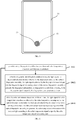
- a number of fingerprint sensors may be regularly distributed under the touch display assembly to form a fingerprint identification area 13 in the touch display assembly 11, as illustrated in FIG. 1 .
- the present disclosure provides an optical fingerprint assembly to reduce the space occupation for arranging the color temperature sensor.
- FIG. 2 is a schematic diagram of an optical fingerprint assembly according to an embodiment.
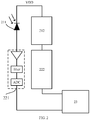
- the optical fingerprint assembly includes a fingerprint sensor 211, a color temperature sensing unit 212, a fingerprint signal processing circuit 221, a color temperature signal processing unit 222 and a control unit 23.
- the fingerprint sensor 211 is configured to collect a light signal for fingerprint identification.
- the color temperature sensing unit 212 is configured to collect a light signal for color temperature detection.
- the fingerprint signal processing circuit 221 is connected to the fingerprint sensor 211 and configured to process the light signal collected by the fingerprint sensor 211 to generate a fingerprint signal.
- the color temperature signal processing unit 222 is connected to the color temperature sensing unit 212 and configured to process the light signal collected by the color temperature sensing unit 212 to generate a color temperature signal.
- the control unit 23 is connected to the fingerprint signal processing circuit 221 and the color temperature signal processing unit 222, respectively, and configured to generate fingerprint information for fingerprint identification according to the fingerprint signal output by the fingerprint signal processing circuit 221 and to generate color temperature information of ambient light according to the color temperature signal output by the color temperature signal processing unit 222.
- the color temperature sensing unit 212 and the color temperature signal processing unit 222 may have various structures, as long as the light signal for color temperature detection can be collected and processed.
- color temperature may not be detected directly according to compound light (i.e., natural light).
- compound light i.e., natural light
- the three primary colors are collected separately, and the color temperature value of the light is acquired according to the collected three primary colors.
- the color temperature sensing unit 212 includes: a red light sensor 2121, a green light sensor 2122 and a blue light sensor 2123.
- the color temperature signal processing circuit 222 includes: a red light signal processing circuit 2221, a green light signal processing circuit 2222, and a blue light signal processing circuit 2223.
- the red light sensor 2121 is configured to collect a red light signal for color temperature detection
- the green light sensor 2122 is configured to collect a green light signal for color temperature detection
- the blue light sensor 2123 is configured to collect a blue light signal for color temperature detection.
- the red light signal processing circuit 2221 has a first end connected to the red light sensor 2121 and a second end connected to the control unit 23, and configured to process the red light signal collected by the red light sensor 2121 to obtain a red light color temperature signal.
- the green light signal processing circuit 2222 has a first end connected to the green light sensor 2122 and a second end connected to the control unit 23, and configured to process the green light signal collected by the green light sensor 2122 to obtain a green light color temperature signal.
- the blue light signal processing circuit 2223 has a first end connected to the blue light sensor 2123 and a second end connected to the control unit 23, and configured to process the blue light signal collected by the blue light sensor 2123 to obtain a blue light color temperature signal.
- the control unit 23 is configured to generate the color temperature information of the ambient light according to the red light color temperature signal output by the red light signal processing circuit 2221, the green light color temperature signal output by the green light signal processing circuit 2222 and the blue color temperature signal output by the blue light signal processing circuit 2223.
- each of the sensors is configured to collect a corresponding light and the light is processed by the corresponding circuit, thus making the processing of different monochromatic lights more accurate, and further improving the accuracy of the finally obtained color temperature.
- the red light signal collected by the red light sensor may not be a pure red light, and may contain a small quantity of monochromatic light other than the red light, such as a green light and a blue light.
- the green light signal collected by the green light sensor may contain monochromatic light other than the green light, such as a red light and a blue light.
- the blue light signal collected by the blue light sensor may contain monochromatic light other than the blue light, such as a red light and a green light. In order to improve the accuracy of the color temperature detection, the collected monochromatic lights may be filtered for purification.
- control unit 23 is further configured to: remove a color temperature signal, contained in the red light color temperature signal, that is processed from the monochromatic light other than the red light; remove a color temperature signal, contained in the green light color temperature signal, that is processed from the monochromatic light other than the green light; and remove a color temperature signal, contained in the blue light color temperature signal, that is processed from the monochromatic light other than the blue light.
- the fingerprint signal processing circuit, the red light signal processing circuit, the green light signal processing circuit, and the blue light signal processing circuit may each include an amplifying circuit, a filtering circuit, and an analog-to-digital conversion circuit sequentially connected in series.
- the fingerprint signal processing circuit 221 includes: a first amplifying circuit, a first filtering circuit and a first analog-to-digital conversion circuit sequentially connected in series.
- the red light signal processing circuit 2221 includes: a second amplifying circuit, a second filtering circuit and a second analog-to-digital conversion circuit sequentially connected in series.
- the green light signal processing circuit 2222 includes: a third amplifying circuit, a third filtering circuit and a third analog-to-digital conversion circuit sequentially connected in series.
- the blue light signal processing circuit 2223 includes: a fourth amplifying circuit, a fourth filtering circuit and a fourth analog-to-digital conversion circuit sequentially connected in series.
- the amplifying circuit, the filter circuit, and analog-to-digital conversion circuit in series described above can be regarded as a rectifier circuit, which can effectively reduce impurity and weakness of the collected light signal.
- the optical fingerprint assembly includes a plurality of color temperature sensing units arranged in different regions of the optical fingerprint assembly.
- the plurality of color temperature sensing units are arranged at different physical locations of the optical fingerprint assembly, to allow the optical fingerprint assembly to collect the color temperature signals at different locations.
- the color temperature signals of the different locations may be integrated and processed, thus reducing the interference of accidental factors on light intensity detection, and making the finally obtained color temperature information of the ambient light more accurate.
- the screen of the electronic device may emit different lights based on the display requirements, which causes interference on the collection of the ambient light.
- the interference of the screen light on the color temperature detection may be reduced to a certain extent.
- the above integration manner may be determined by those skilled in the art according to practices.
- the light intensity signal may be processed by a weighted average algorithm.
- the color temperature sensing unit in order to ensure the integration of the optical fingerprint assembly, may be arranged within a predetermined distance of the fingerprint sensor, such that the color temperature sensing unit is close to the fingerprint sensor in the physical location to further ensure that the color temperature sensing unit and the fingerprint sensor are arranged in the same region, thus avoiding a separate arrangement of the color temperature sensor.
- multiple fingerprint sensors may be required to realize the fingerprint identification.
- the color temperature sensor may also be arranged among the multiple fingerprint sensors, or arranged around a fingerprint identification region formed by the multiple fingerprint sensors. Specific arrangement of the color temperature sensor may be determined by those skilled in the art according to the practices.
- control unit 23 may be a microcontroller unit (MCU), a digital signal processor (DSP), or a central processing unit (CPU). These examples are only illustrative. It should be understood that any hardware that is able to generate the color temperature information of the ambient light according to the color temperature signal and generate the fingerprint information for fingerprint identification according to the fingerprint signal can be used as the control unit of the present disclosure.
- MCU microcontroller unit
- DSP digital signal processor
- CPU central processing unit
- the optical fingerprint assembly provided by the present disclosure may realize both functions of the color temperature detection and the fingerprint identification, such that when the assembly is applied in an electronic device, there is no need to separately arrange the color temperature sensor and the fingerprint sensor, thus avoiding problems caused by the separate arrangement of the color temperature sensor and the reduce of the screen-to-body ratio in the related art.
- monochromatic light signals are obtained, and further integrated and processed to obtain the color temperature information of the ambient light. Since each monochromatic light corresponding to the three primary colors is processed separately, the light processing is more refined, so that the final color temperature information of the ambient light obtained is more accurate, that is, the accuracy of the color temperature detection is improved.
- FIG. 4 is a schematic diagram of a touch display assembly according to an embodiment.
- the touch display assembly includes a glass cover layer 41; a touch layer 42 having a sensing side facing the glass cover layer; a display layer 43 having a light emitting side facing a non-sensing side of the touch layer; and a layer 44 of color temperature detection and fingerprint identification, including an optical fingerprint assembly as described above, and having a light incident side facing a non-light emitting side of the display layer.
- the glass cover layer 41 is made of a transparent glass material for protecting the touch display assembly.
- the sensing side of the touch layer 42 may generate a touch signal corresponding to touch position of a user.
- a way of generating the touch signal may be a sensing method, for example, of a capacitive screen or a resistive screen.
- the display layer 43 is also referred to as a light-emitting layer, and is configured to display an image corresponding to a control signal.
- the layer 44 of color temperature detection and fingerprint identification includes the optical fingerprint assembly as described above.
- the layer of color temperature detection and fingerprint identification of the touch display assembly includes the above-described optical fingerprint assembly.
- the processes of color temperature detection and fingerprint identification are both performed by the touch display assembly, so that the electronic device applying the touch display assembly does not need to have a separate color temperature sensor, and thus such an electronic device has a higher screen-to-body ratio compared with an electronic device with the color temperature sensor separately arranged outside the touch display assembly.
- FIG. 5 is a schematic diagram of an electronic device provided with an optical fingerprint assembly according to an embodiment.
- the electronic device includes a touch display assembly 51 and an optical fingerprint assembly 52 as described above.
- An assembly position of the optical fingerprint assembly 52 corresponds to a fingerprint identification region 53 formed at the touch display assembly 51.
- the electronic device may include the touch display assembly as illustrated in FIG. 4 .
- the user may touch the fingerprint identification region 53 with a finger to allow the electronic device to perform operations of the fingerprint identification.
- multiple fingerprint sensors are regularly distributed in the optical fingerprint assembly 52, and the color temperature sensing unit of the optical fingerprint assembly may be arranged among the multiple fingerprint sensors.
- the location of the color temperature sensor is changed from outside the touch display assembly as a common layout of the related art to the fingerprint identification region of the touch display assembly, avoiding the separate arrangement of the color temperature sensor.
- the optical fingerprint assembly described above is assembled at the fingerprint identification region.
- both the fingerprint sensor and the color temperature sensor are arranged in the touch display assembly, which avoids decrease in the screen-to-body ratio due to the separate arrangement of the color temperature sensor.
- FIG. 6 is a flow chart of a signal processing method according to an embodiment.
- the signal processing method is applied to an electronic device including an optical fingerprint assembly as described above.
- the signal processing method includes the following operations.
- a fingerprint identification condition and a color temperature detection condition are predetermined.
- the optical fingerprint assembly of FIG. 2 or FIG. 3 may be applied, and the optical fingerprint assembly is assembled at the fingerprint identification region of the touch display assembly. Accordingly, both the light signal for fingerprint identification and the light signal for color temperature detection are collected by the touch display assembly, thus avoiding the decrease in the screen-to-body ratio due to the separate arrangement of the color temperature sensor.
- a current operation is an operation of the color temperature detection or the fingerprint identification according to the fingerprint identification condition and the color temperature detection condition which are pre-determined, to allow the corresponding sensor to collect the light signal and the corresponding processing circuit to process the signal.
- the light signal for fingerprint identification is collected by the fingerprint sensor of the optical fingerprint assembly, and the light signal collected by the fingerprint sensor is input into the fingerprint signal processing circuit of the optical fingerprint assembly to generate the fingerprint information for fingerprint identification according to the fingerprint signal output by the fingerprint signal processing circuit.
- the light signal for color temperature detection is collected by the color temperature sensing unit of the optical fingerprint assembly, and the light signal collected by the color temperature sensing unit is input into the color temperature signal processing unit of the optical fingerprint assembly to generate the color temperature information of the ambient light according to the color temperature signal output by the color temperature signal processing unit.
- the user's finger may touch the fingerprint identification region for fingerprint identification to perform operations such as unlocking and payment. If the user does not touch the fingerprint identification region, there is usually no need to perform fingerprint identification operation, but the electronic device may be required to collect the ambient light to make an adaptive adjustment. Therefore, it can be determined whether a light intensity signal or a fingerprint signal needs to be generated by determining whether a touch action is detected in the fingerprint identification region formed at the touch display assembly of the electronic device. When the touch action is detected at the fingerprint identification region, it is determined that the fingerprint identification condition is met. When the touch action is not detected at the fingerprint identification region, the color temperature detection condition is met. In this case, as long as the fingerprint identification region is not touched, the electronic device may perform the color temperature detection.
- the color temperature detection condition and the fingerprint identification condition may also be set in other ways. For example, they can be set according to the functions enabled by the electronic device.
- the color temperature detection condition may be set to be met when a color temperature detection function of the electronic device is turned on, and the fingerprint identification condition may be set to be met when a fingerprint payment function of the electronic device is turned on.
- These examples are only illustrative, and those skilled in the art can set different color temperature detection conditions and fingerprint identification conditions according to practice.
- the other when either one of the color temperature detection condition and the fingerprint identification condition is not met, the other is determined to be met. In another embodiment, the color temperature detection condition and the fingerprint identification condition are independent.
- light signals for generating the color temperature signal and the fingerprint signal are collected by the optical fingerprint assembly arranged in the touch display assembly, thus reducing occupation of the layout space due to the separately arranged color temperature sensor in the related art.
- the user may unlock the device or perform payment.
- the electronic device may change the brightness of the display screen according to the changes in the ambient light.
- the color temperature detection or the fingerprint identification may be performed according to the needs of the user, thus improving the user experience.
- FIG. 7 is a flow chart of a color temperature detection method according to an embodiment.
- the color temperature detection method may be applied to an electronic device including an optical fingerprint assembly as described above.
- the color temperature detection method includes the following operations.
- the color temperature signal generated by the color temperature signal processing unit of the optical fingerprint assembly is acquired through processing the light signal collected by the color temperature sensing unit of the optical fingerprint assembly.
- the color temperature detection may require the red light sensor, the green light sensor, and the blue light sensor to collect different monochromatic light signals, and further integrate the color temperature signals of the ambient light. Therefore, the acquisition of the color temperature signal generated by the color temperature signal processing unit of the optical fingerprint assembly through processing the light signal collected by the color temperature sensing unit of the optical fingerprint assembly includes: acquiring the red light color temperature signal, the green light color temperature signal, and the blue light color temperature signal, in which the red light color temperature signal is obtained by the red light signal processing circuit of the color temperature signal processing unit through processing the red light signal collected by the red light sensor of the color temperature sensing unit, the green light color temperature signal is obtained by the green light signal processing circuit of the color temperature signal processing unit through processing the green light signal collected by the green light sensor of the color temperature sensing unit, and the blue light color temperature signal is obtained by the blue light signal processing circuit of the color temperature signal processing unit through processing the blue light signal collected by the blue light sensor of the color temperature sensing unit.
- a light interference region of the optical fingerprint assembly of the electronic device corresponding to a position of the color temperature sensing unit is acquired.
- the screen may emit lights of different colors, which may interfere with the process of collecting the ambient light by the sensors.
- the received light may be actually a mixed light of the ambient light and the screen light. Therefore, in order to improve the accuracy of the color temperature detection, it is necessary to eliminate the interference of the screen light.
- the acquisition of the light interference region of the optical fingerprint assembly of the electronic device corresponding to the position of the color temperature sensing unit includes: acquiring a red light interference region of the optical fingerprint assembly corresponding to a position of the red light sensor of the color temperature sensing unit, acquiring a green light interference region of the optical fingerprint assembly corresponding to a position of the green light sensor of the color temperature sensing unit, and acquiring a blue light interference region of the optical fingerprint assembly corresponding to a position of the blue light sensor of the color temperature sensing unit.
- the color temperature signal is corrected on the basis of a screen light signal emitted from the light interference region, and the color temperature information of the ambient light is generated according to the corrected color temperature signal.
- the collected color temperature signal of each monochromatic light may be corrected based on each monochromatic light interference region, thus improving the accuracy of the color temperature detection.
- the correction may include: processing the red light color temperature signal on the basis of a screen light signal corresponding to the red light interference region (R interference region) to obtain a corrected red light color temperature signal, processing the green light color temperature signal on the basis of a screen light signal corresponding to the green light interference region (G interference region) to obtain a corrected green light color temperature signal, and processing the blue light color temperature signal on the basis of a screen light signal corresponding to the blue light interference region (B interference region) to obtain a corrected blue light color temperature signal.
- the color temperature signal of each monochromatic light may be processed on the basis of the screen light signal corresponding to each monochromatic light interference region.
- the processing of the red light color temperature signal includes: determining a red light component, a green light component, and a blue light component contained in the screen light signal corresponding to the red light interference region, acquiring a first interference coefficient of the red light component for the red light color temperature signal, a second interference coefficient of the green light component for the red light color temperature signal, and a third interference coefficient of the blue light component for the red light color temperature signal, and correcting the red light color temperature signal on the basis of the red light component and the first interference coefficient, the green light component and the second interference coefficient, and the blue light component and the third interference coefficient.
- the processing of the green light color temperature signal includes: determining a red light component, a green light component, and a blue light component contained in the screen light signal corresponding to the green light interference region, acquiring a fourth interference coefficient of the red light component for the green light color temperature signal, a fifth interference coefficient of the green light component for the green light color temperature signal, and a sixth interference coefficient of the blue light component for the green light color temperature signal, and correcting the green light color temperature signal on the basis of the red light component and the fourth interference coefficient, the green light component and the fifth interference coefficient, and the blue light component and the sixth interference coefficient.
- the processing of the blue light color temperature signal includes: determining a red light component, a green light component, and a blue light component contained in the screen light signal corresponding to the blue light interference region, acquiring a seventh interference coefficient of the red light component for the blue light color temperature signal, an eighth interference coefficient of the green light component for the blue light color temperature signal, and a ninth interference coefficient of the blue light component for the blue light color temperature signal, and correcting the blue light color temperature signal on the basis of the red light component and the seventh interference coefficient, the green light component and the eighth interference coefficient, and the blue light component and the ninth interference coefficient.
- the red light color temperature signal is corrected on the basis of the R interference region.
- Display content of the touch display assembly in the R interference region is acquired, and the display content is analyzed to acquire the monochromatic light weight, i.e., R weight, G weight and B weight.
- Rx represents an initial red light color temperature signal acquired from the processing
- the R weight value is R1
- the first interference coefficient for the red light color temperature signal is k1
- the G weight value is G1
- the second interference coefficient for the red light color temperature signal is k2
- the color temperature information of the ambient light may be generated according to the corrected red light color temperature signal, the corrected green light color temperature signal, and the corrected blue light color temperature signal.
- the above method can firstly acquire the light interference region of the optical fingerprint assembly of the electronic device corresponding to the color temperature sensing unit, and then correct the collected color temperature signal through the light interference region, thus increasing the accuracy of the processed color temperature signal and further improving the accuracy of the generated color temperature information of the ambient light.
- the above method acquires each monochromatic light interference region, and corrects each monochromatic light color temperature signal by analyzing the display content in each monochromatic light interference region, such that the processed monochromatic light color temperature signal is more accurate.
- the above method may correct the color temperature signal at a fine level of the monochromatic light color temperature signal, and further improve the color temperature information of the ambient light obtained based on the corrected color temperature signal.
- the present disclosure also provides embodiments of a signal processing device and a color temperature detection device.
- the signal processing device is applied to an electronic device including an optical fingerprint assembly as described above, or an electronic device as described above.
- the signal processing device includes: a determining unit, configured to determine pre-determined fingerprint identification condition and color temperature detection condition; a first generating unit, configured to, when the fingerprint identification condition is met, collect the light signal for fingerprint identification by the fingerprint sensor of the optical fingerprint assembly, and input the light signal collected by the fingerprint sensor into the fingerprint signal processing circuit of the optical fingerprint assembly to generate the fingerprint information for fingerprint identification according to the fingerprint signal output by the fingerprint signal processing circuit; and a second generating unit, configured to, when the color temperature detection condition is met, collect the light signal for color temperature detection by the color temperature sensing unit of the optical fingerprint assembly, and input the light signal collected by the color temperature sensing unit into the color temperature signal processing unit of the optical fingerprint assembly to generate the color temperature information of the ambient light according to the color temperature signal output by the color temperature signal processing unit.
- FIG. 8 is a block diagram of a signal processing device according to an embodiment. As illustrated in FIG. 8 , the signal processing device includes a determining unit 801, a first generating unit 802, and a second generating unit 803.
- the determining unit 801 is configured to pre-determine a fingerprint identification condition and a color temperature detection condition.
- the first generating unit 802 is configured to, when the fingerprint identification condition is met, collect the light signal for fingerprint identification by the fingerprint sensor of the optical fingerprint assembly, and input the light signal collected by the fingerprint sensor into the fingerprint signal processing circuit of the optical fingerprint assembly to generate the fingerprint information for fingerprint identification according to the fingerprint signal output by the fingerprint signal processing circuit.
- the second generating unit 803 is configured to, when the color temperature detection condition is met, collect the light signal for color temperature detection by the color temperature sensing unit of the optical fingerprint assembly, and input the light signal collected by the color temperature sensing unit into the color temperature signal processing unit of the optical fingerprint assembly to generate the color temperature information of the ambient light according to the color temperature signal output by the color temperature signal processing unit.
- FIG. 9 is a block diagram of a signal processing device according to an embodiment. Based on the signal processing device as illustrated in FIG. 8 , the signal processing device further includes a judging unit 804.
- the judging unit 804 is configured to determine whether a touch action is detected in the fingerprint identification region formed at the touch display assembly of the electronic device.
- the fingerprint identification condition includes detecting the touch action is at the fingerprint identification region.
- the color temperature detection condition includes detecting no touch action at the fingerprint identification region.
- the fingerprint identification condition further includes determining a pressing force corresponding to the touch action to be equal to or more than a preset pressure threshold when the touch action is detected at the fingerprint identification region.
- the color temperature detection condition further includes detecting no touch action at the fingerprint identification region during a preset time period.
- the color temperature detection condition and the fingerprint identification condition are independent of each other.
- the color temperature detection device is applied to an electronic device including an optical fingerprint assembly as described above, or an electronic device as described above.
- the color temperature detection device includes: a first acquiring unit, configured to acquire the color temperature signal generated by the color temperature signal processing unit of the optical fingerprint assembly through processing the light signal collected by the color temperature sensing unit of the optical fingerprint assembly; a second acquiring unit, configured to acquire a light interference region of the optical fingerprint assembly of the electronic device corresponding to a position of the color temperature sensing unit; and an information generating unit, configured to correct the color temperature signal on the basis of a screen light signal emitted from the light interference region, and generate the color temperature information of the ambient light according to the corrected color temperature signal.
- FIG. 10 is a block diagram of a color temperature detection device according to an embodiment. As illustrated in FIG. 10 , the color temperature detection device includes a first acquiring unit 1001, a second acquiring unit 1002, and an information generating unit 1003.
- the first acquiring unit 1001 is configured to acquire the color temperature signal generated by the color temperature signal processing unit of the optical fingerprint assembly through processing the light signal collected by the color temperature sensing unit of the optical fingerprint assembly.
- the second acquiring unit 1002 is configured to acquire a light interference region of the optical fingerprint assembly of the electronic device corresponding to a position of the color temperature sensing unit.
- the information generating unit 1003 is configured to correct the color temperature signal on the basis of a screen light signal emitted from the light interference region, and generate the color temperature information of the ambient light according to the corrected color temperature signal.
- the first acquiring unit 1001 is further configured to acquire the red light color temperature signal, the green light color temperature signal, and the blue light color temperature signal, in which the red light color temperature signal is obtained by the red light signal processing circuit of the color temperature signal processing unit through processing the red light signal collected by the red light sensor of the color temperature sensing unit, the green light color temperature signal is obtained by the green light signal processing circuit of the color temperature signal processing unit through processing the green light signal collected by the green light sensor of the color temperature sensing unit, and the blue light color temperature signal is obtained by the blue light signal processing circuit of the color temperature signal processing unit through processing the blue light signal collected by the blue light sensor of the color temperature sensing unit.
- the second acquiring unit 1002 is further configured to acquire a red light interference region of the optical fingerprint assembly corresponding to a position of the red light sensor of the color temperature sensing unit, acquire a green light interference region of the optical fingerprint assembly corresponding to a position of the green light sensor of the color temperature sensing unit, and acquire a blue light interference region of the optical fingerprint assembly corresponding to a position of the blue light sensor of the color temperature sensing unit.
- the information generating unit 1003 is further configured to process the red light color temperature signal on the basis of a screen light signal corresponding to the red light interference region to obtain a corrected red light color temperature signal, process the green light color temperature signal on the basis of a screen light signal corresponding to the green light interference region to obtain a corrected green light color temperature signal, and process the blue light color temperature signal on the basis of a screen light signal corresponding to the blue light interference region to obtain a corrected blue light color temperature signal; and generate the color temperature information of the ambient light according to the corrected red light color temperature signal, the corrected green light color temperature signal and the corrected blue light color temperature signal.
- the information generating unit 1003 is further configured to: determine a red light component, a green light component, and a blue light component contained in the screen light signal corresponding to the red light interference region, acquire a first interference coefficient of the red light component for the red light color temperature signal, a second interference coefficient of the green light component for the red light color temperature signal, and a third interference coefficient of the blue light component for the red light color temperature signal, and correct the red light color temperature signal on the basis of the red light component and the first interference coefficient, the green light component and the second interference coefficient, and the blue light component and the third interference coefficient; determine a red light component, a green light component, and a blue light component contained in the screen light signal corresponding to the green light interference region, acquire a fourth interference coefficient of the red light component for the green light color temperature signal, a fifth interference coefficient of the green light component for the green light color temperature signal, and a sixth interference coefficient of the blue light component for the green light color temperature signal, and correct the green light color temperature signal on the basis of the red light component
- the device embodiments described above are only exemplary.
- the units described as separate components may or may not be physically separated, and the components illustrated as the units may or may not be physical units, that is, they may be located in the same place, or it can be distributed to multiple networks. Some or all of the units can be selected according to practice to achieve the objectives of the present disclosure.
- the present disclosure provides a signal processing/color temperature detection device, including a memory having stored therein an instruction; and a processor configured to execute the instruction for implementing the methods described above.
- the signal processing method may include: pre-determining a fingerprint identification condition and a color temperature detection condition; when the fingerprint identification condition is met, collecting the light signal for fingerprint identification by the fingerprint sensor of the optical fingerprint assembly, inputting the light signal collected by the fingerprint sensor into the fingerprint signal processing circuit of the optical fingerprint assembly to generate the fingerprint information for fingerprint identification according to the fingerprint signal output by the fingerprint signal processing circuit; and when the color temperature detection condition is met, collecting the light signal for color temperature detection by the color temperature sensing unit of the optical fingerprint assembly, inputting the light signal collected by the color temperature sensing unit into the color temperature signal processing unit of the optical fingerprint assembly to generate the color temperature information of the ambient light according to the color temperature signal output by the color temperature signal processing unit.
- the present disclosure also provides an electronic apparatus, including a memory stored therein one or more programs.
- the one or more programs including instructions for realizing the signal processing/color temperature detection methods described above are executed by one or more processors.
- the signal processing method may include: pre-determining a fingerprint identification condition and a color temperature detection condition; when the fingerprint identification condition is met, collecting the light signal for fingerprint identification by the fingerprint sensor of the optical fingerprint assembly, inputting the light signal collected by the fingerprint sensor into the fingerprint signal processing circuit of the optical fingerprint assembly to generate the fingerprint information for fingerprint identification according to the fingerprint signal output by the fingerprint signal processing circuit; and when the color temperature detection condition is met, collecting the light signal for color temperature detection by the color temperature sensing unit of the optical fingerprint assembly, inputting the light signal collected by the color temperature sensing unit into the color temperature signal processing unit of the optical fingerprint assembly to generate the color temperature information of the ambient light according to the color temperature signal output by the color temperature signal processing unit.
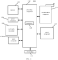
- FIG. 11 is a block diagram of an electronic device 1100 for signal processing and color temperature detection according to an embodiment.
- the device 1100 may be a mobile phone, a computer, a digital broadcasting terminal, a messaging device, a game console, a tablet device, a medical device, exercise equipment, a personal digital assistant, and the like.
- the device 1100 may include one or more of the following components: a processing component 1102, a memory 1104, a power component 1106, a multimedia component 1108, an audio component 1110, an input/output (I/O) interface 1112, a sensor component 1114, and a communication component 1116.
- a processing component 1102 a memory 1104, a power component 1106, a multimedia component 1108, an audio component 1110, an input/output (I/O) interface 1112, a sensor component 1114, and a communication component 1116.
- the processing component 1102 typically controls overall operations of the device 1100, such as the operations associated with display, telephone calls, data communications, camera operations, and recording operations.
- the processing component 1102 may include one or more processors 1120 to execute instructions to perform all or part of the steps in the above described methods.
- the processing component 1102 may include one or more modules which facilitate the interaction between the processing component 1102 and other components.
- the processing component 1102 may include a multimedia module to facilitate the interaction between the multimedia component 1108 and the processing component 1102.
- the memory 1104 is configured to store various types of data to support the operation of the device 1100. Examples of such data include instructions for any applications or methods operated on the device 1100, contact data, phonebook data, messages, pictures, video, etc.
- the memory 1104 may be implemented using any type of volatile or non-volatile memory devices, or a combination thereof, such as a static random access memory (SRAM), an electrically erasable programmable read-only memory (EEPROM), an erasable programmable read-only memory (EPROM), a programmable read-only memory (PROM), a read-only memory (ROM), a magnetic memory, a flash memory, a magnetic or optical disk.
- SRAM static random access memory
- EEPROM electrically erasable programmable read-only memory
- EPROM erasable programmable read-only memory
- PROM programmable read-only memory
- ROM read-only memory
- magnetic memory a magnetic memory
- flash memory a flash memory
- magnetic or optical disk a magnetic
- the power component 1106 provides power to various components of the device 1100.
- the power component 1106 may include a power management system, one or more power sources, and any other components associated with the generation, management, and distribution of power in the device 1100.
- the multimedia component 1108 includes a screen providing an output interface between the device 1100 and the user.
- the screen may include a liquid crystal display (LCD) and a touch panel (TP). If the screen includes the touch panel, the screen may be implemented as a touch screen to receive input signals from the user.
- the touch panel includes one or more touch sensors to sense touches, swipes, and gestures on the touch panel. The touch sensors may not only sense a boundary of a touch or swipe action, but also sense a period of time and a pressure associated with the touch or swipe action.
- the multimedia component 1108 includes a front camera and/or a rear camera. The front camera and the rear camera may receive an external multimedia datum while the device 1100 is in an operation mode, such as a photographing mode or a video mode. Each of the front camera and the rear camera may be a fixed optical lens system or have focus and optical zoom capability.
- the audio component 1110 is configured to output and/or input audio signals.
- the audio component 1110 includes a microphone ("MIC") configured to receive an external audio signal when the device 1100 is in an operation mode, such as a call mode, a recording mode, and a voice identification mode.
- the received audio signal may be further stored in the memory 1104 or transmitted via the communication component 1116.
- the audio component 1110 further includes a speaker to output audio signals.
- the I/O interface 1112 provides an interface between the processing component 1102 and peripheral interface modules, such as a keyboard, a click wheel, buttons, and the like.
- the buttons may include, but are not limited to, a home button, a volume button, a starting button, and a locking button.
- the sensor component 1114 includes one or more sensors to provide status assessments of various aspects of the device 1100. For instance, the sensor component 1114 may detect an open/closed status of the device 1100, relative positioning of components, e.g., the display and the keypad, of the device 1100, a change in position of the device 1100 or a component of the device 1100, a presence or absence of user contact with the device 1100, an orientation or an acceleration/deceleration of the device 1100, and a change in temperature of the device 1100.
- the sensor component 1114 may include a proximity sensor configured to detect the presence of nearby objects without any physical contact.
- the sensor component 1114 may also include a light sensor, such as a CMOS or CCD image sensor, for use in imaging applications.
- the sensor component 1114 may also include an accelerometer sensor, a gyroscope sensor, a magnetic sensor, a pressure sensor, or a temperature sensor.
- the communication component 1116 is configured to facilitate communication, wired or wirelessly, between the device 1100 and other devices.
- the device 1100 can access a wireless network based on a communication standard, such as WiFi, 4G, or 5G, or a combination thereof.
- the communication component 1116 receives a broadcast signal or broadcast associated information from an external broadcast management system via a broadcast channel.
- the communication component 1116 further includes a near field communication (NFC) module to facilitate short-range communications.
- NFC near field communication
- the communication component 1116 may be implemented based on a radio frequency identification (RFID) technology, an infrared data association (IrDA) technology, an ultra-wideband (UWB) technology, a Bluetooth (BT) technology, and other technologies.
- RFID radio frequency identification
- IrDA infrared data association
- UWB ultra-wideband
- BT Bluetooth
- the device 1100 may be implemented with one or more application specific integrated circuits (ASICs), digital signal processors (DSPs), digital signal processing devices (DSPDs), programmable logic devices (PLDs), field programmable gate arrays (FPGAs), controllers, micro-controllers, microprocessors, or other electronic components, for performing the above described methods.
- ASICs application specific integrated circuits
- DSPs digital signal processors
- DSPDs digital signal processing devices
- PLDs programmable logic devices
- FPGAs field programmable gate arrays
- controllers micro-controllers, microprocessors, or other electronic components, for performing the above described methods.
- non-transitory computer-readable storage medium having stored therein a computer instruction, such as included in the memory 1104, executable by the processor 1120 in the device 1100, for performing the above-described methods.
- the non-transitory computer-readable storage medium may be a ROM, a RAM, a CD-ROM, a magnetic tape, a floppy disc, an optical data storage device, and the like.
- the optical fingerprint assembly integrated with the fingerprint sensor and the color temperature sensing unit is provided, which is applied to the electronic device. Since the optical fingerprint assembly may realize functions of color temperature detection and fingerprint identification, there is no need to separately arrange a color temperature sensor in the device, thus increasing the screen-to-body ratio and optimizing the display effect of the electronic device.
- the layout space available for arranging other components in the electronic device is increased, making the layout of the optical fingerprint assembly more flexible, reducing the difficulty of the arrangement of components in the development process, and thus reducing the development cost.
Landscapes
- Engineering & Computer Science (AREA)
- Theoretical Computer Science (AREA)
- Physics & Mathematics (AREA)
- General Physics & Mathematics (AREA)
- Multimedia (AREA)
- General Health & Medical Sciences (AREA)
- Health & Medical Sciences (AREA)
- Human Computer Interaction (AREA)
- General Engineering & Computer Science (AREA)
- Computer Vision & Pattern Recognition (AREA)
- Life Sciences & Earth Sciences (AREA)
- Spectroscopy & Molecular Physics (AREA)
- Artificial Intelligence (AREA)
- Evolutionary Computation (AREA)
- Analytical Chemistry (AREA)
- Pathology (AREA)
- Immunology (AREA)
- Biochemistry (AREA)
- Chemical & Material Sciences (AREA)
- Data Mining & Analysis (AREA)
- Computing Systems (AREA)
- Medical Informatics (AREA)
- Databases & Information Systems (AREA)
- Software Systems (AREA)
- Vascular Medicine (AREA)
- Mathematical Physics (AREA)
- Bioinformatics & Cheminformatics (AREA)
- Bioinformatics & Computational Biology (AREA)
- Evolutionary Biology (AREA)
- Image Input (AREA)
- Measurement Of The Respiration, Hearing Ability, Form, And Blood Characteristics Of Living Organisms (AREA)
- Telephone Function (AREA)
Applications Claiming Priority (1)
| Application Number | Priority Date | Filing Date | Title |
|---|---|---|---|
| CN202010500252.6A CN113761977A (zh) | 2020-06-04 | 2020-06-04 | 光学指纹模组和信号处理方法 |
Publications (2)
| Publication Number | Publication Date |
|---|---|
| EP3920084A1 true EP3920084A1 (de) | 2021-12-08 |
| EP3920084B1 EP3920084B1 (de) | 2025-04-30 |
Family
ID=73856827
Family Applications (1)
| Application Number | Title | Priority Date | Filing Date |
|---|---|---|---|
| EP20216516.3A Active EP3920084B1 (de) | 2020-06-04 | 2020-12-22 | Optische fingerabdruckanordnung und signalverarbeitungsverfahren |
Country Status (5)
| Country | Link |
|---|---|
| US (1) | US11474026B2 (de) |
| EP (1) | EP3920084B1 (de) |
| JP (1) | JP7127105B2 (de) |
| KR (1) | KR20210150944A (de) |
| CN (1) | CN113761977A (de) |
Families Citing this family (3)
| Publication number | Priority date | Publication date | Assignee | Title |
|---|---|---|---|---|
| CN116346980A (zh) * | 2021-12-23 | 2023-06-27 | 北京小米移动软件有限公司 | 色温检测方法、装置及介质 |
| WO2024177250A1 (ko) * | 2023-02-21 | 2024-08-29 | 삼성전자주식회사 | 표시 상태를 변경하는 전자 장치, 방법, 및 컴퓨터 판독가능 저장매체 |
| CN120254758B (zh) * | 2025-06-03 | 2025-08-01 | 福建师范大学协和学院 | 一种应用于可见光定位的rss指纹重构方法 |
Family Cites Families (11)
| Publication number | Priority date | Publication date | Assignee | Title |
|---|---|---|---|---|
| US10043052B2 (en) * | 2011-10-27 | 2018-08-07 | Synaptics Incorporated | Electronic device packages and methods |
| CN105787328B (zh) * | 2016-03-14 | 2018-03-02 | 广东欧珀移动通信有限公司 | 一种提高解锁速度的方法及移动终端 |
| KR102359276B1 (ko) * | 2017-03-24 | 2022-02-07 | 삼성전자주식회사 | 전자 장치의 화이트 밸런스 기능 제어 방법 및 장치 |
| KR102040388B1 (ko) * | 2017-04-19 | 2019-11-04 | 선전 구딕스 테크놀로지 컴퍼니, 리미티드 | 광 강도 검출 방법, 장치 및 스마트 단말기 |
| CN107944423A (zh) * | 2017-12-08 | 2018-04-20 | 上海摩软通讯技术有限公司 | 移动终端和光学指纹模组及其控制方法 |
| CN108229372B (zh) * | 2017-12-29 | 2021-08-10 | 努比亚技术有限公司 | 指纹识别方法、移动终端及计算机可读存储介质 |
| CN108073912B (zh) * | 2018-01-03 | 2021-01-26 | 京东方科技集团股份有限公司 | 指纹识别装置和指纹识别设备 |
| CN108762573A (zh) * | 2018-06-04 | 2018-11-06 | 维沃移动通信有限公司 | 一种触摸屏、触控压力检测方法及终端 |
| CN108833716A (zh) * | 2018-06-29 | 2018-11-16 | 北京小米移动软件有限公司 | 光照强度确定方法及装置 |
| CN110139088B (zh) * | 2019-05-28 | 2021-03-02 | Oppo广东移动通信有限公司 | 色温补偿方法、电子设备及计算机可读存储介质 |
| CN110969146B (zh) * | 2019-12-20 | 2023-12-29 | 京东方科技集团股份有限公司 | 指纹识别组件、显示基板、显示面板和指纹识别方法 |
-
2020
- 2020-06-04 CN CN202010500252.6A patent/CN113761977A/zh active Pending
- 2020-12-01 KR KR1020200165604A patent/KR20210150944A/ko not_active Ceased
- 2020-12-11 JP JP2020206163A patent/JP7127105B2/ja active Active
- 2020-12-21 US US17/129,125 patent/US11474026B2/en active Active
- 2020-12-22 EP EP20216516.3A patent/EP3920084B1/de active Active
Non-Patent Citations (5)
| Title |
|---|
| AMS: "ams Product Brief Page 1 [v1-03] 2018-Dec-19 Document Feedback TCS3701 ALS/Color and Proximity Sensor for Use Behind OLED Displays", 19 December 2018 (2018-12-19), XP055686100, Retrieved from the Internet <URL:https://www.mouser.com/pdfDocs/TCS3701_PB000125_1-00.pdf> [retrieved on 20200415] * |
| AMS: "TCS3701 Color and Proximity Sensor", 28 August 2019 (2019-08-28), XP055803691, Retrieved from the Internet <URL:https://ams.com/TCS3701> [retrieved on 20210511] * |
| ANONYMOUS: "New light sensor brings dream of the all-screen phone one step closer - MSPoweruser", 9 January 2019 (2019-01-09), XP055803686, Retrieved from the Internet <URL:https://mspoweruser.com/new-light-sensor-brings-dream-of-the-all-screen-phone-moves-one-step-closer/> [retrieved on 20210511] * |
| ANONYMOUS: "Qualcomm 3D Sonic Sensor enables OEMs top-notch security and accuracy [video]", 20 February 2019 (2019-02-20), XP055803699, Retrieved from the Internet <URL:https://www.qualcomm.com/news/onq/2019/02/20/samsung-galaxy-s10-taps-qualcomm-3d-sonic-sensor-top-notch-security-and-accuracy> [retrieved on 20210511] * |
| ANONYMOUS: "Samsung Galaxy S10 Review - Sensors", 19 March 2019 (2019-03-19), XP055803097, Retrieved from the Internet <URL:https://www.devicespecifications.com/en/editor-review/d1fc9b/6> [retrieved on 20210510] * |
Also Published As
| Publication number | Publication date |
|---|---|
| US11474026B2 (en) | 2022-10-18 |
| CN113761977A (zh) | 2021-12-07 |
| EP3920084B1 (de) | 2025-04-30 |
| JP7127105B2 (ja) | 2022-08-29 |
| JP2021190077A (ja) | 2021-12-13 |
| KR20210150944A (ko) | 2021-12-13 |
| US20210381957A1 (en) | 2021-12-09 |
Similar Documents
| Publication | Publication Date | Title |
|---|---|---|
| US11698297B2 (en) | Methods and devices for detecting ambient light based on different states of flexible screen, and storage medium | |
| US10997477B2 (en) | Foreign matter recognition method and device | |
| US20190353520A1 (en) | Method and apparatus for acquiring ambient light brightness | |
| CN104700816B (zh) | 屏幕亮度设置方法及装置 | |
| US10002283B2 (en) | Mobile device and screen module thereof, method and apparatus for acquiring fingerprint and electronic device | |
| US10284773B2 (en) | Method and apparatus for preventing photograph from being shielded | |
| EP3168782A1 (de) | Rastermodul und fingerabdruckerfassungsverfahren | |
| EP3046042B1 (de) | Vorrichtung zur implementierung von home tasten und fingerabdruckidentifizierung durch gemensaimen sensor | |
| US9922227B2 (en) | Apparatus and method for implementing touch control and fingerprint identification | |
| US20160202834A1 (en) | Unlocking method and terminal device using the same | |
| CN109766043A (zh) | 电子设备的操作方法和电子设备 | |
| EP3920084B1 (de) | Optische fingerabdruckanordnung und signalverarbeitungsverfahren | |
| US10248855B2 (en) | Method and apparatus for identifying gesture | |
| EP3130985B1 (de) | Verfahren und vorrichtung zur detektion von druck in einem mobilen endgerät | |
| CN104934016B (zh) | 屏幕显示方法及装置 | |
| CN112714205A (zh) | 环境光照强度确定方法、装置及存储介质 | |
| WO2018164411A1 (ko) | 카메라 모듈을 구비한 전자 장치 및 전자 장치 제어 방법 | |
| US10885298B2 (en) | Method and device for optical fingerprint recognition, and computer-readable storage medium | |
| CN113851096B (zh) | 亮度检测方法、装置及存储介质 | |
| CN115931120A (zh) | 光感校准方法、装置、终端设备及介质 | |
| EP3629318A2 (de) | Verfahren und vorrichtung zur kompensation des betriebsparameters einer anzeigeschaltung | |
| CN118836971A (zh) | 环境光照度确定方法及其装置 | |
| CN111103997B (zh) | 防误触方法、设备及可读存储介质 | |
| CN114414042A (zh) | 环境光的检测方法、装置、存储介质和电子设备 | |
| CN113739912B (zh) | 光学信号检测模组和光强检测方法 |
Legal Events
| Date | Code | Title | Description |
|---|---|---|---|
| PUAI | Public reference made under article 153(3) epc to a published international application that has entered the european phase |
Free format text: ORIGINAL CODE: 0009012 |
|
| STAA | Information on the status of an ep patent application or granted ep patent |
Free format text: STATUS: THE APPLICATION HAS BEEN PUBLISHED |
|
| AK | Designated contracting states |
Kind code of ref document: A1 Designated state(s): AL AT BE BG CH CY CZ DE DK EE ES FI FR GB GR HR HU IE IS IT LI LT LU LV MC MK MT NL NO PL PT RO RS SE SI SK SM TR |
|
| B565 | Issuance of search results under rule 164(2) epc |
Effective date: 20210528 |
|
| STAA | Information on the status of an ep patent application or granted ep patent |
Free format text: STATUS: REQUEST FOR EXAMINATION WAS MADE |
|
| 17P | Request for examination filed |
Effective date: 20220531 |
|
| RBV | Designated contracting states (corrected) |
Designated state(s): AL AT BE BG CH CY CZ DE DK EE ES FI FR GB GR HR HU IE IS IT LI LT LU LV MC MK MT NL NO PL PT RO RS SE SI SK SM TR |
|
| STAA | Information on the status of an ep patent application or granted ep patent |
Free format text: STATUS: EXAMINATION IS IN PROGRESS |
|
| 17Q | First examination report despatched |
Effective date: 20230816 |
|
| REG | Reference to a national code |
Ref country code: DE Ref legal event code: R079 Ipc: G06V0010140000 Ref country code: DE Ref legal event code: R079 Ref document number: 602020050344 Country of ref document: DE Free format text: PREVIOUS MAIN CLASS: G06K0009000000 Ipc: G06V0010140000 |
|
| GRAP | Despatch of communication of intention to grant a patent |
Free format text: ORIGINAL CODE: EPIDOSNIGR1 |
|
| STAA | Information on the status of an ep patent application or granted ep patent |
Free format text: STATUS: GRANT OF PATENT IS INTENDED |
|
| RIC1 | Information provided on ipc code assigned before grant |
Ipc: G06V 40/13 20220101ALI20241112BHEP Ipc: G06V 10/80 20220101ALI20241112BHEP Ipc: G06V 10/14 20220101AFI20241112BHEP |
|
| INTG | Intention to grant announced |
Effective date: 20241203 |
|
| GRAS | Grant fee paid |
Free format text: ORIGINAL CODE: EPIDOSNIGR3 |
|
| P01 | Opt-out of the competence of the unified patent court (upc) registered |
Free format text: CASE NUMBER: APP_8243/2025 Effective date: 20250218 |
|
| GRAA | (expected) grant |
Free format text: ORIGINAL CODE: 0009210 |
|
| STAA | Information on the status of an ep patent application or granted ep patent |
Free format text: STATUS: THE PATENT HAS BEEN GRANTED |
|
| AK | Designated contracting states |
Kind code of ref document: B1 Designated state(s): AL AT BE BG CH CY CZ DE DK EE ES FI FR GB GR HR HU IE IS IT LI LT LU LV MC MK MT NL NO PL PT RO RS SE SI SK SM TR |
|
| REG | Reference to a national code |
Ref country code: CH Ref legal event code: EP Ref country code: GB Ref legal event code: FG4D |
|
| REG | Reference to a national code |
Ref country code: IE Ref legal event code: FG4D |
|
| REG | Reference to a national code |
Ref country code: DE Ref legal event code: R096 Ref document number: 602020050344 Country of ref document: DE |
|
| REG | Reference to a national code |
Ref country code: NL Ref legal event code: MP Effective date: 20250430 |
|
| REG | Reference to a national code |
Ref country code: AT Ref legal event code: MK05 Ref document number: 1790784 Country of ref document: AT Kind code of ref document: T Effective date: 20250430 |
|
| PG25 | Lapsed in a contracting state [announced via postgrant information from national office to epo] |
Ref country code: FI Free format text: LAPSE BECAUSE OF FAILURE TO SUBMIT A TRANSLATION OF THE DESCRIPTION OR TO PAY THE FEE WITHIN THE PRESCRIBED TIME-LIMIT Effective date: 20250430 Ref country code: ES Free format text: LAPSE BECAUSE OF FAILURE TO SUBMIT A TRANSLATION OF THE DESCRIPTION OR TO PAY THE FEE WITHIN THE PRESCRIBED TIME-LIMIT Effective date: 20250430 Ref country code: PT Free format text: LAPSE BECAUSE OF FAILURE TO SUBMIT A TRANSLATION OF THE DESCRIPTION OR TO PAY THE FEE WITHIN THE PRESCRIBED TIME-LIMIT Effective date: 20250901 |
|
| REG | Reference to a national code |
Ref country code: LT Ref legal event code: MG9D |
|
| PG25 | Lapsed in a contracting state [announced via postgrant information from national office to epo] |
Ref country code: NO Free format text: LAPSE BECAUSE OF FAILURE TO SUBMIT A TRANSLATION OF THE DESCRIPTION OR TO PAY THE FEE WITHIN THE PRESCRIBED TIME-LIMIT Effective date: 20250730 Ref country code: GR Free format text: LAPSE BECAUSE OF FAILURE TO SUBMIT A TRANSLATION OF THE DESCRIPTION OR TO PAY THE FEE WITHIN THE PRESCRIBED TIME-LIMIT Effective date: 20250731 |
|
| PG25 | Lapsed in a contracting state [announced via postgrant information from national office to epo] |
Ref country code: PL Free format text: LAPSE BECAUSE OF FAILURE TO SUBMIT A TRANSLATION OF THE DESCRIPTION OR TO PAY THE FEE WITHIN THE PRESCRIBED TIME-LIMIT Effective date: 20250430 Ref country code: NL Free format text: LAPSE BECAUSE OF FAILURE TO SUBMIT A TRANSLATION OF THE DESCRIPTION OR TO PAY THE FEE WITHIN THE PRESCRIBED TIME-LIMIT Effective date: 20250430 |
|
| PG25 | Lapsed in a contracting state [announced via postgrant information from national office to epo] |
Ref country code: BG Free format text: LAPSE BECAUSE OF FAILURE TO SUBMIT A TRANSLATION OF THE DESCRIPTION OR TO PAY THE FEE WITHIN THE PRESCRIBED TIME-LIMIT Effective date: 20250430 |
|
| PG25 | Lapsed in a contracting state [announced via postgrant information from national office to epo] |
Ref country code: HR Free format text: LAPSE BECAUSE OF FAILURE TO SUBMIT A TRANSLATION OF THE DESCRIPTION OR TO PAY THE FEE WITHIN THE PRESCRIBED TIME-LIMIT Effective date: 20250430 |
|
| PG25 | Lapsed in a contracting state [announced via postgrant information from national office to epo] |
Ref country code: AT Free format text: LAPSE BECAUSE OF FAILURE TO SUBMIT A TRANSLATION OF THE DESCRIPTION OR TO PAY THE FEE WITHIN THE PRESCRIBED TIME-LIMIT Effective date: 20250430 |
|
| PG25 | Lapsed in a contracting state [announced via postgrant information from national office to epo] |
Ref country code: RS Free format text: LAPSE BECAUSE OF FAILURE TO SUBMIT A TRANSLATION OF THE DESCRIPTION OR TO PAY THE FEE WITHIN THE PRESCRIBED TIME-LIMIT Effective date: 20250731 |
|
| PG25 | Lapsed in a contracting state [announced via postgrant information from national office to epo] |
Ref country code: IS Free format text: LAPSE BECAUSE OF FAILURE TO SUBMIT A TRANSLATION OF THE DESCRIPTION OR TO PAY THE FEE WITHIN THE PRESCRIBED TIME-LIMIT Effective date: 20250830 |
|
| PG25 | Lapsed in a contracting state [announced via postgrant information from national office to epo] |
Ref country code: LV Free format text: LAPSE BECAUSE OF FAILURE TO SUBMIT A TRANSLATION OF THE DESCRIPTION OR TO PAY THE FEE WITHIN THE PRESCRIBED TIME-LIMIT Effective date: 20250430 |
|
| PGFP | Annual fee paid to national office [announced via postgrant information from national office to epo] |
Ref country code: GB Payment date: 20251127 Year of fee payment: 6 |
|
| PG25 | Lapsed in a contracting state [announced via postgrant information from national office to epo] |
Ref country code: SM Free format text: LAPSE BECAUSE OF FAILURE TO SUBMIT A TRANSLATION OF THE DESCRIPTION OR TO PAY THE FEE WITHIN THE PRESCRIBED TIME-LIMIT Effective date: 20250430 Ref country code: DK Free format text: LAPSE BECAUSE OF FAILURE TO SUBMIT A TRANSLATION OF THE DESCRIPTION OR TO PAY THE FEE WITHIN THE PRESCRIBED TIME-LIMIT Effective date: 20250430 |
|
| PG25 | Lapsed in a contracting state [announced via postgrant information from national office to epo] |
Ref country code: CZ Free format text: LAPSE BECAUSE OF FAILURE TO SUBMIT A TRANSLATION OF THE DESCRIPTION OR TO PAY THE FEE WITHIN THE PRESCRIBED TIME-LIMIT Effective date: 20250430 |
|
| PG25 | Lapsed in a contracting state [announced via postgrant information from national office to epo] |
Ref country code: EE Free format text: LAPSE BECAUSE OF FAILURE TO SUBMIT A TRANSLATION OF THE DESCRIPTION OR TO PAY THE FEE WITHIN THE PRESCRIBED TIME-LIMIT Effective date: 20250430 |
|
| PG25 | Lapsed in a contracting state [announced via postgrant information from national office to epo] |
Ref country code: RO Free format text: LAPSE BECAUSE OF FAILURE TO SUBMIT A TRANSLATION OF THE DESCRIPTION OR TO PAY THE FEE WITHIN THE PRESCRIBED TIME-LIMIT Effective date: 20250430 Ref country code: SK Free format text: LAPSE BECAUSE OF FAILURE TO SUBMIT A TRANSLATION OF THE DESCRIPTION OR TO PAY THE FEE WITHIN THE PRESCRIBED TIME-LIMIT Effective date: 20250430 |
|
| PG25 | Lapsed in a contracting state [announced via postgrant information from national office to epo] |
Ref country code: IT Free format text: LAPSE BECAUSE OF FAILURE TO SUBMIT A TRANSLATION OF THE DESCRIPTION OR TO PAY THE FEE WITHIN THE PRESCRIBED TIME-LIMIT Effective date: 20250430 |
|
| REG | Reference to a national code |
Ref country code: DE Ref legal event code: R097 Ref document number: 602020050344 Country of ref document: DE |
|
| PLBE | No opposition filed within time limit |
Free format text: ORIGINAL CODE: 0009261 |
|
| STAA | Information on the status of an ep patent application or granted ep patent |
Free format text: STATUS: NO OPPOSITION FILED WITHIN TIME LIMIT |
|
| REG | Reference to a national code |
Ref country code: CH Ref legal event code: L10 Free format text: ST27 STATUS EVENT CODE: U-0-0-L10-L00 (AS PROVIDED BY THE NATIONAL OFFICE) Effective date: 20260311 |
|
| 26N | No opposition filed |
Effective date: 20260202 |