EP3919961B1 - Head-up display device - Google Patents
Head-up display device Download PDFInfo
- Publication number
- EP3919961B1 EP3919961B1 EP19912723.4A EP19912723A EP3919961B1 EP 3919961 B1 EP3919961 B1 EP 3919961B1 EP 19912723 A EP19912723 A EP 19912723A EP 3919961 B1 EP3919961 B1 EP 3919961B1
- Authority
- EP
- European Patent Office
- Prior art keywords
- light
- display
- virtual image
- head
- unit
- Prior art date
- Legal status (The legal status is an assumption and is not a legal conclusion. Google has not performed a legal analysis and makes no representation as to the accuracy of the status listed.)
- Active
Links
Images


Classifications
-
- H—ELECTRICITY
- H04—ELECTRIC COMMUNICATION TECHNIQUE
- H04N—PICTORIAL COMMUNICATION, e.g. TELEVISION
- H04N9/00—Details of colour television systems
- H04N9/12—Picture reproducers
- H04N9/31—Projection devices for colour picture display, e.g. using electronic spatial light modulators [ESLM]
- H04N9/3141—Constructional details thereof
- H04N9/315—Modulator illumination systems
- H04N9/3161—Modulator illumination systems using laser light sources
-
- H—ELECTRICITY
- H04—ELECTRIC COMMUNICATION TECHNIQUE
- H04N—PICTORIAL COMMUNICATION, e.g. TELEVISION
- H04N9/00—Details of colour television systems
- H04N9/12—Picture reproducers
- H04N9/31—Projection devices for colour picture display, e.g. using electronic spatial light modulators [ESLM]
- H04N9/3129—Projection devices for colour picture display, e.g. using electronic spatial light modulators [ESLM] scanning a light beam on the display screen
-
- B—PERFORMING OPERATIONS; TRANSPORTING
- B60—VEHICLES IN GENERAL
- B60K—ARRANGEMENT OR MOUNTING OF PROPULSION UNITS OR OF TRANSMISSIONS IN VEHICLES; ARRANGEMENT OR MOUNTING OF PLURAL DIVERSE PRIME-MOVERS IN VEHICLES; AUXILIARY DRIVES FOR VEHICLES; INSTRUMENTATION OR DASHBOARDS FOR VEHICLES; ARRANGEMENTS IN CONNECTION WITH COOLING, AIR INTAKE, GAS EXHAUST OR FUEL SUPPLY OF PROPULSION UNITS IN VEHICLES
- B60K35/00—Instruments specially adapted for vehicles; Arrangement of instruments in or on vehicles
- B60K35/20—Output arrangements, i.e. from vehicle to user, associated with vehicle functions or specially adapted therefor
- B60K35/21—Output arrangements, i.e. from vehicle to user, associated with vehicle functions or specially adapted therefor using visual output, e.g. blinking lights or matrix displays
- B60K35/23—Head-up displays [HUD]
- B60K35/233—Head-up displays [HUD] controlling the size or position in display areas of virtual images depending on the condition of the vehicle or the driver
-
- B—PERFORMING OPERATIONS; TRANSPORTING
- B60—VEHICLES IN GENERAL
- B60K—ARRANGEMENT OR MOUNTING OF PROPULSION UNITS OR OF TRANSMISSIONS IN VEHICLES; ARRANGEMENT OR MOUNTING OF PLURAL DIVERSE PRIME-MOVERS IN VEHICLES; AUXILIARY DRIVES FOR VEHICLES; INSTRUMENTATION OR DASHBOARDS FOR VEHICLES; ARRANGEMENTS IN CONNECTION WITH COOLING, AIR INTAKE, GAS EXHAUST OR FUEL SUPPLY OF PROPULSION UNITS IN VEHICLES
- B60K35/00—Instruments specially adapted for vehicles; Arrangement of instruments in or on vehicles
- B60K35/20—Output arrangements, i.e. from vehicle to user, associated with vehicle functions or specially adapted therefor
- B60K35/21—Output arrangements, i.e. from vehicle to user, associated with vehicle functions or specially adapted therefor using visual output, e.g. blinking lights or matrix displays
- B60K35/23—Head-up displays [HUD]
- B60K35/234—Head-up displays [HUD] controlling the brightness, colour or contrast of virtual images depending on the driving conditions or on the condition of the vehicle or the driver
-
- B—PERFORMING OPERATIONS; TRANSPORTING
- B60—VEHICLES IN GENERAL
- B60K—ARRANGEMENT OR MOUNTING OF PROPULSION UNITS OR OF TRANSMISSIONS IN VEHICLES; ARRANGEMENT OR MOUNTING OF PLURAL DIVERSE PRIME-MOVERS IN VEHICLES; AUXILIARY DRIVES FOR VEHICLES; INSTRUMENTATION OR DASHBOARDS FOR VEHICLES; ARRANGEMENTS IN CONNECTION WITH COOLING, AIR INTAKE, GAS EXHAUST OR FUEL SUPPLY OF PROPULSION UNITS IN VEHICLES
- B60K35/00—Instruments specially adapted for vehicles; Arrangement of instruments in or on vehicles
- B60K35/20—Output arrangements, i.e. from vehicle to user, associated with vehicle functions or specially adapted therefor
- B60K35/28—Output arrangements, i.e. from vehicle to user, associated with vehicle functions or specially adapted therefor characterised by the type of the output information, e.g. video entertainment or vehicle dynamics information; characterised by the purpose of the output information, e.g. for attracting the attention of the driver
-
- B—PERFORMING OPERATIONS; TRANSPORTING
- B60—VEHICLES IN GENERAL
- B60K—ARRANGEMENT OR MOUNTING OF PROPULSION UNITS OR OF TRANSMISSIONS IN VEHICLES; ARRANGEMENT OR MOUNTING OF PLURAL DIVERSE PRIME-MOVERS IN VEHICLES; AUXILIARY DRIVES FOR VEHICLES; INSTRUMENTATION OR DASHBOARDS FOR VEHICLES; ARRANGEMENTS IN CONNECTION WITH COOLING, AIR INTAKE, GAS EXHAUST OR FUEL SUPPLY OF PROPULSION UNITS IN VEHICLES
- B60K35/00—Instruments specially adapted for vehicles; Arrangement of instruments in or on vehicles
- B60K35/40—Instruments specially adapted for improving the visibility thereof to the user, e.g. fogging prevention or anti-reflection arrangements
- B60K35/425—Anti-reflection arrangements
-
- B—PERFORMING OPERATIONS; TRANSPORTING
- B60—VEHICLES IN GENERAL
- B60K—ARRANGEMENT OR MOUNTING OF PROPULSION UNITS OR OF TRANSMISSIONS IN VEHICLES; ARRANGEMENT OR MOUNTING OF PLURAL DIVERSE PRIME-MOVERS IN VEHICLES; AUXILIARY DRIVES FOR VEHICLES; INSTRUMENTATION OR DASHBOARDS FOR VEHICLES; ARRANGEMENTS IN CONNECTION WITH COOLING, AIR INTAKE, GAS EXHAUST OR FUEL SUPPLY OF PROPULSION UNITS IN VEHICLES
- B60K35/00—Instruments specially adapted for vehicles; Arrangement of instruments in or on vehicles
- B60K35/80—Arrangements for controlling instruments
- B60K35/81—Arrangements for controlling instruments for controlling displays
-
- G—PHYSICS
- G02—OPTICS
- G02B—OPTICAL ELEMENTS, SYSTEMS OR APPARATUS
- G02B27/00—Optical systems or apparatus not provided for by any of the groups G02B1/00 - G02B26/00, G02B30/00
- G02B27/01—Head-up displays
- G02B27/0101—Head-up displays characterised by optical features
-
- H—ELECTRICITY
- H04—ELECTRIC COMMUNICATION TECHNIQUE
- H04N—PICTORIAL COMMUNICATION, e.g. TELEVISION
- H04N9/00—Details of colour television systems
- H04N9/12—Picture reproducers
- H04N9/31—Projection devices for colour picture display, e.g. using electronic spatial light modulators [ESLM]
- H04N9/3141—Constructional details thereof
- H04N9/315—Modulator illumination systems
- H04N9/3158—Modulator illumination systems for controlling the spectrum
-
- B—PERFORMING OPERATIONS; TRANSPORTING
- B60—VEHICLES IN GENERAL
- B60K—ARRANGEMENT OR MOUNTING OF PROPULSION UNITS OR OF TRANSMISSIONS IN VEHICLES; ARRANGEMENT OR MOUNTING OF PLURAL DIVERSE PRIME-MOVERS IN VEHICLES; AUXILIARY DRIVES FOR VEHICLES; INSTRUMENTATION OR DASHBOARDS FOR VEHICLES; ARRANGEMENTS IN CONNECTION WITH COOLING, AIR INTAKE, GAS EXHAUST OR FUEL SUPPLY OF PROPULSION UNITS IN VEHICLES
- B60K2360/00—Indexing scheme associated with groups B60K35/00 or B60K37/00 relating to details of instruments or dashboards
- B60K2360/16—Type of output information
- B60K2360/177—Augmented reality
-
- B—PERFORMING OPERATIONS; TRANSPORTING
- B60—VEHICLES IN GENERAL
- B60K—ARRANGEMENT OR MOUNTING OF PROPULSION UNITS OR OF TRANSMISSIONS IN VEHICLES; ARRANGEMENT OR MOUNTING OF PLURAL DIVERSE PRIME-MOVERS IN VEHICLES; AUXILIARY DRIVES FOR VEHICLES; INSTRUMENTATION OR DASHBOARDS FOR VEHICLES; ARRANGEMENTS IN CONNECTION WITH COOLING, AIR INTAKE, GAS EXHAUST OR FUEL SUPPLY OF PROPULSION UNITS IN VEHICLES
- B60K2360/00—Indexing scheme associated with groups B60K35/00 or B60K37/00 relating to details of instruments or dashboards
- B60K2360/16—Type of output information
- B60K2360/178—Warnings
-
- B—PERFORMING OPERATIONS; TRANSPORTING
- B60—VEHICLES IN GENERAL
- B60K—ARRANGEMENT OR MOUNTING OF PROPULSION UNITS OR OF TRANSMISSIONS IN VEHICLES; ARRANGEMENT OR MOUNTING OF PLURAL DIVERSE PRIME-MOVERS IN VEHICLES; AUXILIARY DRIVES FOR VEHICLES; INSTRUMENTATION OR DASHBOARDS FOR VEHICLES; ARRANGEMENTS IN CONNECTION WITH COOLING, AIR INTAKE, GAS EXHAUST OR FUEL SUPPLY OF PROPULSION UNITS IN VEHICLES
- B60K35/00—Instruments specially adapted for vehicles; Arrangement of instruments in or on vehicles
- B60K35/10—Input arrangements, i.e. from user to vehicle, associated with vehicle functions or specially adapted therefor
-
- B—PERFORMING OPERATIONS; TRANSPORTING
- B60—VEHICLES IN GENERAL
- B60K—ARRANGEMENT OR MOUNTING OF PROPULSION UNITS OR OF TRANSMISSIONS IN VEHICLES; ARRANGEMENT OR MOUNTING OF PLURAL DIVERSE PRIME-MOVERS IN VEHICLES; AUXILIARY DRIVES FOR VEHICLES; INSTRUMENTATION OR DASHBOARDS FOR VEHICLES; ARRANGEMENTS IN CONNECTION WITH COOLING, AIR INTAKE, GAS EXHAUST OR FUEL SUPPLY OF PROPULSION UNITS IN VEHICLES
- B60K35/00—Instruments specially adapted for vehicles; Arrangement of instruments in or on vehicles
- B60K35/60—Instruments characterised by their location or relative disposition in or on vehicles
-
- G—PHYSICS
- G02—OPTICS
- G02B—OPTICAL ELEMENTS, SYSTEMS OR APPARATUS
- G02B27/00—Optical systems or apparatus not provided for by any of the groups G02B1/00 - G02B26/00, G02B30/00
- G02B27/01—Head-up displays
- G02B27/0101—Head-up displays characterised by optical features
- G02B2027/0141—Head-up displays characterised by optical features characterised by the informative content of the display
Definitions
- the present invention relates to a head-up display apparatus.
- a head-up display apparatus for displaying information for a user on a windshield has been becoming widespread.
- a head-up display apparatus projects certain information onto a combiner composed of a transparent substrate or onto a windshield, so that a user such as a driver visually can recognize a virtual image.
- a technique for displaying a plurality of virtual images at places having different distances from a user's viewpoint has been developed.
- a lens is disposed in a part of a light-emitting surface of a drawing device for generating display light, and a virtual image formed by light that passed through the lens and a virtual image that is formed by light that does not pass through the lens are recognized as if they are located at places having different distances from a user's viewpoint.
- a self-luminous type display panel is disposed in a reflection member that reflects projected display light. Further, a virtual image formed by reflected display light and a virtual image displayed by the self-luminous type display panel are recognized as if they are located at places having different distances from a user's viewpoint.
- Patent Literature 3 and its US counterpart, Patent Literature 4 disclose a head-up display apparatus, where, in order to display a first virtual image, a first image display device projects a first image onto a windshield via a glare trap part, and in order to display a second virtual image having a different display distance, a second image display device generates a second image on a functional film, mounted on a glare trap part, and projects the second image onto the windshield.
- Patent literature 5 discloses a head-up display is mounted to a vehicle having a windshield, including a display element configured to display an image, a first optical system configured to reflect the image displayed by the display element and project the image onto the windshield; and a second optical system configured to reflect the image displayed by the display element and project the image onto the windshield.
- the image projected with the first optical system is projected onto the windshield at a position below a position of the image projected with the second optical system.
- Patent Literature 6 and its US counterpart, Patent Literature 7, disclose a head-up display which projects display light on a transmission/reflection part to display a first virtual image in an area in which the virtual image can be displayed, said area being superimposed on an actual view outside of a vehicle, wherein, when deviation occurs in the relative positions of the actual view and the transmission/reflection part from the perspective of a viewer, a control unit enlarges a virtual image display area, which sets the range in which the first virtual image is displayed within the area in which the virtual image can be displayed, so as to be larger than normal.
- Patent Literature 1 since a screen image generated by one drawing device is divided into two images, there is a limit to the size of each of the virtual images. Further, if two drawing devices are disposed in order to eliminate the limitation in regard to the size of each virtual image, the size of the device may increase. In the technique disclosed in Patent Literature 2, when an image generated by the self-luminous type display panel is displayed as a virtual image, the maximum size of the virtual image becomes the actual size of the display panel, so that the expandability thereof is poor. Further, in order to display an image on the self-luminous type display panel in an enlarged manner, a combiner is required for the virtual-image projection surface.
- An embodiment according to the present disclosure has been made in order to solve the above-described problem, and provides a head-up display apparatus of which the degree of freedom in designing is high and the expandability is excellent.
- a head-up display apparatus projects a plurality of virtual images of which depths perceived by a user with respect to a virtual-image display unit disposed in front of the user are different from each other.
- the head-up display apparatus includes a first projection apparatus and a second projection apparatus.
- the first projection apparatus includes a first display-light emitting unit configured to emit first display light, and a concave mirror configured to reflect the first display light and thereby emit reflected light thereof, and the first projection apparatus is configured to enable the user to perceive a first virtual image by projecting the reflected light onto a virtual-image display unit.
- the second projection apparatus includes a second display-light generation unit configured to let the reflected light pass therethrough and generate second display light different from the first display light, and the second projection apparatus is configured to enable the user to perceive a second virtual image by projecting the generated second display light onto the virtual-image display unit.
- the embodiment it is possible to provide a head-up display apparatus of which the degree of freedom in designing is high and the expandability is excellent.
- a head-up display apparatus is an apparatus that projects a plurality of virtual images of which depths perceived by a user with respect to a virtual-image display unit disposed in front of the user are different from each other. More specifically, a head-up display apparatus according to this embodiment is an apparatus that is installed in an automobile, and is an apparatus that displays information for a driver, i.e., a user, by projecting a virtual image onto a windshield of the automobile or onto a combiner using the windshield or the combiner as a virtual-image display unit.
- FIG. 1 is a schematic diagram showing the configuration of the head-up display apparatus according to the first embodiment.
- Fig. 1 schematically shows an automobile 1, a user U of the automobile 1, and a head-up display apparatus 10. Note that, in Fig. 1 , a right-handed orthogonal coordinate system is shown for the sake of convenience for explaining a positional relation among components.
- the X-axis coincides with the longitudinal direction of the automobile 1, and the X-axis positive direction coincides with the direction from the front of the automobile 1 toward the rear thereof.
- the Y-axis coincides with the left/right direction of the automobile 1, and the Y-axis positive direction coincides with the direction from the left of the automobile 1 toward the right thereof.
- the Z-axis coincides with the vertical direction of the automobile 1, and the Z axis positive direction coincides with the direction from the bottom of the automobile 1 to the top thereof.
- the X-, Y-, and Z-axis directions in Fig. 1 coincide with the X-, Y-, and Z-axis directions in that orthogonal coordinate system, respectively.
- the head-up display apparatus 10 is housed in a dashboard of the automobile 1 and projects a first virtual image V101 and a second virtual image V102 onto a windshield WS.
- the head-up display apparatus includes, as its main components, a first projection apparatus 101 and a second projection apparatus 102.
- the first projection apparatus 101 projects the first virtual image V101 onto the windshield WS.
- the first projection apparatus 101 includes, as its main components, a first display-light emitting unit 110, a reflecting mirror 120, and a concave mirror 130.
- the first display-light emitting unit 110 includes a first light source 111 and a first image display unit 112.
- the first display-light emitting unit 110 generates a first display light L10 by making light emitted from the first light source 111 pass through the first image display unit 112, and emits the generated first display light L10.
- the first display light L10 is display light for forming the first virtual image V101, and contains information to be displayed as the first virtual image V101 for the user U.
- the first light source 111 is composed of, for example, an LED(s) (Light Emitting Diode(s)) or a lamp.
- the first image display unit 112 is composed of a transmission-type liquid-crystal panel or the like.
- the first display-light emitting unit 110 projects the generated first display light L10 onto the reflecting mirror 120.
- the reflecting mirror 120 reflects the first display light L10 received from the first display-light emitting unit 110 and projects the reflected light onto the concave mirror 130.
- the concave mirror 130 generates reflected light L11 as the mirror having the concave shape receives and reflects the first display light L10 received through the reflecting mirror 120.
- the concave mirror 130 is configured so as to project the reflected light L11 onto the windshield WS. Further, in the concave mirror 130, the curved surface is formed so that the reflected light L11 projected by the concave mirror 130 forms an image having no distortion as viewed from the user U. Further, the first display light L10 is projected in a magnified manner by the concave mirror 130. Therefore, the first virtual image V101 perceived by the user U is larger than the image displayed by the first image display unit 112.
- the reflected light L11 projected by the concave mirror 130 is projected onto the windshield WS after passing through a second display-light generation unit 140 (which will be described later).
- the first projection apparatus 101 enables the user U to perceive the first virtual image V101.
- the concave mirror 130 includes a drive unit (not shown) that rotates the concave mirror 130 around a shaft 131 parallel to the Y-axis over a predetermined angle by using the shaft 131 as a fulcrum.
- the drive unit rotates the concave mirror 130
- the concave mirror 130 can change the direction of the reflected light L11.
- the head-up display apparatus 10 can suitably adjust the change in the place where the first virtual image V101 is displayed, which is caused as the height of the viewpoint of the user U changes.
- the second projection apparatus 102 projects the second virtual image V102 onto the windshield WS.
- the second projection apparatus 102 includes, as its main components, the second display-light generation unit 140 and an excitation-light emitting unit 150.
- the second display-light generation unit 140 lets the reflected light L11 generated by the first projection apparatus 101 pass therethrough, and generates second display light L21 different from the first display light L10.
- the second display light L21 generated by the second display-light generation unit 140 is projected onto the windshield WS, and thereby enables the user U to perceive the second virtual image V102.
- the second display-light generation unit 140 is formed by using a plate-like transparent member having a concavely-curved upper surface as a substrate.
- highly-transparent plastic such as polycarbonate or acryl, or highly-transparent glass is used for the substrate.
- the second display-light generation unit 140 prevents external light coming from the outside of the automobile 1 from being reflected thereon into the interior of the vehicle. Further, the second display-light generation unit 140 prevents foreign substances from entering the head-up display apparatus 10. Note that the second display-light generation unit 140 is also referred to as a clear cover.
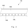
- the second display-light generation unit 140 will be further described with reference to Fig. 2.
- Fig. 2 is a cross-sectional view of the second display-light generation unit in the head-up display apparatus according to the first embodiment.
- the second display-light generation unit 140 is composed of, as viewed from the top, a coating layer 140S, a substrate 140G, and a self-luminous layer 140L.
- the coating layer 140S is an AR (Anti-Reflection) coating that suppresses reflection of light and reflection of images. Further, the coating layer 140S may be one having a scratch-resisting function.
- the substrate 140G is formed of a transparent polycarbonate material. Further, the substrate 140G has a thickness of, for example, about 1 millimeter in order to suppress unintended refraction which would otherwise occur when the reflected light L11 projected from the first projection apparatus 101 passes therethrough.
- the self-luminous layer 140L contains a self-luminous material 140A in a binder material having a high visible-light transmittance.
- the self-luminous material 140A is a material that emits fluorescence, which is visible light, by receiving specific excitation light. Further, the specific excitation light is light having a specific frequency. For example, the specific excitation light is ultraviolet light. That is, the self-luminous material 140A in this embodiment is a material that emits fluorescence when it receives ultraviolet light having a specific frequency. Note that the position of the self-luminous material 140A is not limited to the lower layer of the second display-light generation unit 140, but may be an intermediate layer and/or an upper layer thereof.
- Fig. 3 is a schematic diagram showing a configuration of an excitation-light emitting unit according to the first embodiment.
- the excitation-light emitting unit 150 is a laser projector apparatus that projects ultraviolet laser light, which serves as excitation light, onto the second display-light generation unit 140.
- the excitation-light emitting unit 150 includes, as its main components, a control unit 151 and a laser light emitting unit 152.
- the control unit 151 includes a CPU (Central Processing Unit), a driver IC (Integrated Circuit), and the like, and has a function of appropriately controlling each component of the laser light emitting unit 152.
- CPU Central Processing Unit
- driver IC Integrated Circuit
- the laser light emitting unit 152 includes a laser light source unit 153 and a laser scanning unit 154.
- the laser light source unit 153 includes a laser diode(s) 153LD, a mirror 153M, and a photodetector 153PD.
- the laser diode 153LD generates ultraviolet laser light at a predetermined timing according to an instruction from the control unit 151, and supplies the generated ultraviolet laser light to the mirror 153M.
- the mirror 153M lets part of the ultraviolet laser light received from the laser diode 153LD pass therethrough and thereby outputs that part of the ultraviolet laser light, and reflects and supplies other part of the ultraviolet laser light to the photodetector 153PD.
- the photodetector 153PD detects (i.e., measures) the intensity of the ultraviolet laser light supplied from the mirror 153M, and feeds back a signal that is generated based on the detection to the control unit 151.
- the laser scanning unit 154 generates excitation light L20 from the ultraviolet laser light received from the laser light source unit 153.
- the laser scanning unit 154 includes a first scanner mirror 154H and a second scanner mirror 154V.
- the first scanner mirror 154H makes the ultraviolet laser light perform to-and-fro movements over a predetermined angle along the horizontal scanning line of the second virtual image V102.
- the second scanner mirror 154V makes the ultraviolet laser light perform to-and-fro movements over a predetermined angle along the vertical scanning line of the second virtual image v102.
- the laser scanning unit 154 generates surface excitation light L20 by appropriately performing the scanning operations of the ultraviolet laser light, which is supplied from one point and travels in a straight line, along the two scanning lines orthogonal to each other.
- the excitation-light emitting unit 150 generates excitation light for forming the second virtual image V102, and projects the generated excitation light onto the second display-light generation unit 140. Further, when the excitation light is projected from the excitation-light emitting unit 150 onto the second display-light generation unit 140 as described above, a part of the second display-light generation unit 140 on which the excitation light is incident emits fluorescence. Then, the fluorescence emitted by the second display-light generation unit 140 is projected onto the windshield WS and is perceived by the user U as the second virtual image V102.
- the head-up display apparatus 10 projects each of the reflected light L11 generated by the first projection apparatus 101 and the second display light L21 generated by the second projection apparatus 102 onto the windshield WS.
- the length of the optical path for the first virtual image V101 from the first display-light emitting unit 110 to the windshield WS is longer than that of the optical path for the second virtual image V102 from the second display-light generation unit 140 to the windshield WS. Therefore, the user U perceives that the distance from his/her viewpoint to the first virtual image V101 is longer than the distance from his/her viewpoint to the second virtual image V102.
- the user U perceives that the first virtual image V101 is located more distant from him/her than the second virtual image V102 is. That is, the head-up display apparatus 10 can project a plurality of virtual images of which depths perceived by the user U are different from each other.
- the head-up display apparatus 10 is configured so that the place where the first virtual image V101 is displayed can be adjusted. That is, the head-up display apparatus 10 is configured so that the reflected light L11 can be moved within the range of the second display-light generation unit 140. Therefore, the head-up display apparatus 10 is configured so that the reflected light L11 becomes smaller than the second display-light generation unit 140 at the place where it passes through the second display-light generation unit 140. Therefore, the angle of view of the first virtual image V101 is smaller than that of the second virtual image V102. Alternatively, it can be said that the first virtual image V101 is included (i.e., confined) in the range in which the second virtual image V102 can be displayed.
- the head-up display apparatus 10 can display the second virtual image V102 of which the angle of view is larger than that of the first virtual image V101, it realizes a head-up display apparatus of which the expandability is excellent. Note that, in the above-described configuration, it is possible to make the angle of view of the second virtual image V102 smaller than that of the first virtual image V101.
- the excitation-light emitting unit 150 can change the direction of the projection of the excitation light L20 according to the position of the concave mirror 130. Therefore, in the head-up display apparatus 10, when the place where the first virtual image V101 is displayed is adjusted by driving the concave mirror 130, the place where the second virtual image V102 is displayed can be adjusted according to the place where the first virtual image V101 is displayed.
- the control unit 151 detects the angle of the concave mirror 130, and adjusts the timing at which the laser light source unit 153 emits light according to the detected angle of the concave mirror 130. By adjusting the light emitting timing of the laser light source unit 153, the excitation-light emitting unit 150 can adjust the direction of the image projected by the laser light emitting unit 152.
- the position of the excitation-light emitting unit 150 is not limited to the position shown in the figure as long as it does not interfere with either of the first display light L10 generated by the first projection apparatus and the reflected light L11 thereof. That is, the excitation-light emitting unit 150 of the second projection apparatus 102 may have any configuration as long as it projects excitation light to the second display-light generation unit 140 in an incident direction different from the incident direction in which the reflected light L11 is projected onto the second display-light generation unit 140. Therefore, the degree of freedom in designing of the second projection apparatus 102 is high. That is, according to the first embodiment, it is possible to provide a head-up display apparatus of which the degree of freedom in spatial designing is high and the increase in volume is minimized.
- Fig. 4 shows an example of a virtual image projected by the head-up display apparatus.
- the virtual image shown in the figure shows a virtual image perceived by the user U.
- the user U perceives a first virtual image V101 and a second virtual image V102.
- a traveling speed (60 km/h) of the automobile 1 and guide information (i.e., an arrow indicating a right turn) for a traveling route are displayed.
- guide information i.e., an arrow indicating a right turn
- a user U can obtain information necessary for the driving as appropriate while minimizing the movement of the line of sight of the user U and the change of the focal distance of the eyes during the driving.
- the head-up display apparatus 10 can make the user U have a sense of urgency. Further, by using the second virtual image V102 having an angle of view larger than that of the first virtual image V101, it is possible to effectively call attention to the user U without interfering with the display of normal information displayed during the traveling. Further, the brightness of the second display light L21 for displaying the second virtual image V102 can be changed by changing the intensity of the ultraviolet laser light. Therefore, the head-up display apparatus 10 can adjust the brightness of the second virtual image V102 by changing the intensity of the excitation light.
- the head-up display apparatus 10 is not limited to the above-described configuration.
- the laser light emitting unit 152 which is one of the components of the excitation-light emitting unit 150, may be configured so as to emit a surface emitting laser.
- the laser scanning unit 154 may be a DLP (Digital Light Processing) unit.
- the self-luminous material 140A may be contained in a plurality of layers in the second display-light generation unit 140.
- the self-luminous material(s) may be one(s) that emits fluorescence, which is visible light, by receiving excitation light having a different frequency in each of the layers.
- the head-up display apparatus displays an image for forming a second virtual image on the second display-light generation unit, which is a clear cover, and thereby projects a plurality of virtual images of which depths are different from each other while minimizing the increase in volume thereof. Therefore, according to the first embodiment, it is possible to provide the head-up display apparatus of which the degree of freedom in designing is high and the expandability is excellent.
- a configuration for generating a second virtual image in a head-up display apparatus according to the second embodiment is different from that in the first embodiment. Differences from the first embodiment will be described hereinafter.
- Fig. 5 is a schematic diagram showing a configuration of a head-up display apparatus according to the second embodiment.
- the head-up display apparatus 20 shown in the figure includes a second projection apparatus 202 in place of the second projection apparatus 102.
- the second projection apparatus 202 includes, in place of the laser projector apparatus for projecting ultraviolet laser light, a transmission-type display panel and a driver circuit for driving the display panel.
- the second projection apparatus 202 includes a second display-light generation unit 240 and a second display-light control unit 212.
- the second display-light generation unit 240 includes a transmission-type display panel 241 which uses a plate-like member having a high visible-light transmittance as a substrate.
- the transmission-type display panel 241 is composed of, for example, an organic EL (Electro Luminescence) display panel. That is, the second display-light generation unit 240 includes a layer that lets reflected light L11, which is visible light, pass therethrough and emits light by itself.
- the display panel 241 may be a transmission-type liquid-crystal panel instead of the organic EL display panel.
- the second display-light control unit 212 is connected to the second display-light generation unit 240, and is a circuit including a driver IC for controlling the display panel 241 of the second display-light generation unit 240. Note that the second display-light control unit 212 can be disposed at an arbitrary place as long as it does not interfere with either of the first display light L10 generated by the first projection apparatus and the reflected light L11 thereof.
- the head-up display apparatus 20 displays an image for forming a second virtual image on the second display-light generation unit, which is a clear cover, and thereby projects a plurality of virtual images of which depths are different from each other while minimizing the increase in volume. Therefore, according to the second embodiment, it is possible to provide the head-up display apparatus of which the degree of freedom in designing is high and the expandability is excellent.
- the above-described head-up display apparatus can be applied to vehicles other than automobiles, such as aircrafts and ships. Further, the objects or the like to which the above-described head-up display apparatus is applied is not limited to vehicles. That is, the head-up display apparatus may be applied to driving simulators for automobiles, flight simulators for airplanes, video-game apparatuses, and the like.
Landscapes
- Engineering & Computer Science (AREA)
- Combustion & Propulsion (AREA)
- Transportation (AREA)
- Mechanical Engineering (AREA)
- Chemical & Material Sciences (AREA)
- Physics & Mathematics (AREA)
- Optics & Photonics (AREA)
- Signal Processing (AREA)
- Multimedia (AREA)
- General Physics & Mathematics (AREA)
- Instrument Panels (AREA)
- Mechanical Optical Scanning Systems (AREA)
- Fittings On The Vehicle Exterior For Carrying Loads, And Devices For Holding Or Mounting Articles (AREA)
Description
- The present invention relates to a head-up display apparatus.
- In vehicles such as automobiles, a head-up display apparatus for displaying information for a user on a windshield has been becoming widespread. A head-up display apparatus projects certain information onto a combiner composed of a transparent substrate or onto a windshield, so that a user such as a driver visually can recognize a virtual image. Further, in order to improve the usefulness of such a head-up display apparatus, a technique for displaying a plurality of virtual images at places having different distances from a user's viewpoint has been developed.
- In a head-up display apparatus disclosed in
Patent Literature 1, a lens is disposed in a part of a light-emitting surface of a drawing device for generating display light, and a virtual image formed by light that passed through the lens and a virtual image that is formed by light that does not pass through the lens are recognized as if they are located at places having different distances from a user's viewpoint. - Further, in a display apparatus disclosed in Patent Literature 2, a self-luminous type display panel is disposed in a reflection member that reflects projected display light. Further, a virtual image formed by reflected display light and a virtual image displayed by the self-luminous type display panel are recognized as if they are located at places having different distances from a user's viewpoint.
- Patent Literature 3 and its US counterpart, Patent Literature 4, disclose a head-up display apparatus, where, in order to display a first virtual image, a first image display device projects a first image onto a windshield via a glare trap part, and in order to display a second virtual image having a different display distance, a second image display device generates a second image on a functional film, mounted on a glare trap part, and projects the second image onto the windshield.
- Patent literature 5 discloses a head-up display is mounted to a vehicle having a windshield, including a display element configured to display an image, a first optical system configured to reflect the image displayed by the display element and project the image onto the windshield; and a second optical system configured to reflect the image displayed by the display element and project the image onto the windshield. The image projected with the first optical system is projected onto the windshield at a position below a position of the image projected with the second optical system.
- Patent Literature 6 and its US counterpart, Patent Literature 7, disclose a head-up display which projects display light on a transmission/reflection part to display a first virtual image in an area in which the virtual image can be displayed, said area being superimposed on an actual view outside of a vehicle, wherein, when deviation occurs in the relative positions of the actual view and the transmission/reflection part from the perspective of a viewer, a control unit enlarges a virtual image display area, which sets the range in which the first virtual image is displayed within the area in which the virtual image can be displayed, so as to be larger than normal.
-
- Patent Literature 1:
Japanese Unexamined Patent Application Publication No. 2018-086915 - Patent Literature 2:
Japanese Unexamined Patent Application Publication No. 2006-171465 - Patent Literature 3: Publication No., "
WO 2018/117012 A1 "; - Patent Literature 4: Publication No., "
US 2019/0235240 A1 "; - Patent Literature 5: Publication No., "
US 2016/0202479 A1 "; - Patent Literature 6: Publication No., "
WO 2018/088362 A1 "; - Patent Literature 7: Publication No., "
US 2019/0258057 A1 ". - However, in the technique disclosed in
Patent Literature 1, since a screen image generated by one drawing device is divided into two images, there is a limit to the size of each of the virtual images. Further, if two drawing devices are disposed in order to eliminate the limitation in regard to the size of each virtual image, the size of the device may increase. In the technique disclosed in Patent Literature 2, when an image generated by the self-luminous type display panel is displayed as a virtual image, the maximum size of the virtual image becomes the actual size of the display panel, so that the expandability thereof is poor. Further, in order to display an image on the self-luminous type display panel in an enlarged manner, a combiner is required for the virtual-image projection surface. - An embodiment according to the present disclosure has been made in order to solve the above-described problem, and provides a head-up display apparatus of which the degree of freedom in designing is high and the expandability is excellent.
- A head-up display apparatus according to an embodiment projects a plurality of virtual images of which depths perceived by a user with respect to a virtual-image display unit disposed in front of the user are different from each other. The head-up display apparatus includes a first projection apparatus and a second projection apparatus. The first projection apparatus includes a first display-light emitting unit configured to emit first display light, and a concave mirror configured to reflect the first display light and thereby emit reflected light thereof, and the first projection apparatus is configured to enable the user to perceive a first virtual image by projecting the reflected light onto a virtual-image display unit. The second projection apparatus includes a second display-light generation unit configured to let the reflected light pass therethrough and generate second display light different from the first display light, and the second projection apparatus is configured to enable the user to perceive a second virtual image by projecting the generated second display light onto the virtual-image display unit.
- According to the embodiment, it is possible to provide a head-up display apparatus of which the degree of freedom in designing is high and the expandability is excellent.
-
-
Fig. 1 is a schematic diagram showing a configuration of a head-up display apparatus according to a first embodiment; -
Fig. 2 is a cross-sectional view of a second display-light generation unit in the head-up display apparatus according to the first embodiment; -
Fig. 3 is a schematic diagram showing a configuration of an excitation-light emitting unit according to the first embodiment; -
Fig. 4 shows an example of a virtual image projected by a head-up display apparatus; and -
Fig. 5 is a schematic diagram showing a configuration of a head-up display apparatus according to a second embodiment. - For clarifying the explanation, the following description and the drawings are partially omitted and simplified as appropriate. The same reference numerals (or symbols) are assigned to the same elements throughout the drawings and redundant explanations thereof are omitted as appropriate.
- Embodiments according to the present invention will be described hereinafter with reference to the drawings. A head-up display apparatus according to this embodiment is an apparatus that projects a plurality of virtual images of which depths perceived by a user with respect to a virtual-image display unit disposed in front of the user are different from each other. More specifically, a head-up display apparatus according to this embodiment is an apparatus that is installed in an automobile, and is an apparatus that displays information for a driver, i.e., a user, by projecting a virtual image onto a windshield of the automobile or onto a combiner using the windshield or the combiner as a virtual-image display unit.
- A configuration of the head-up display apparatus according to the first embodiment will be described with reference to
Fig. 1. Fig. 1 is a schematic diagram showing the configuration of the head-up display apparatus according to the first embodiment.Fig. 1 schematically shows anautomobile 1, a user U of theautomobile 1, and a head-updisplay apparatus 10. Note that, inFig. 1 , a right-handed orthogonal coordinate system is shown for the sake of convenience for explaining a positional relation among components. In the drawings, the X-axis coincides with the longitudinal direction of theautomobile 1, and the X-axis positive direction coincides with the direction from the front of theautomobile 1 toward the rear thereof. The Y-axis coincides with the left/right direction of theautomobile 1, and the Y-axis positive direction coincides with the direction from the left of theautomobile 1 toward the right thereof. The Z-axis coincides with the vertical direction of theautomobile 1, and the Z axis positive direction coincides with the direction from the bottom of theautomobile 1 to the top thereof. Further, inFig. 2 and the subsequent drawings, when an orthogonal coordinate system is shown, the X-, Y-, and Z-axis directions inFig. 1 coincide with the X-, Y-, and Z-axis directions in that orthogonal coordinate system, respectively. - As shown in the figure, the head-up
display apparatus 10 is housed in a dashboard of theautomobile 1 and projects a first virtual image V101 and a second virtual image V102 onto a windshield WS. The head-up display apparatus includes, as its main components, afirst projection apparatus 101 and asecond projection apparatus 102. - The
first projection apparatus 101 projects the first virtual image V101 onto the windshield WS. Thefirst projection apparatus 101 includes, as its main components, a first display-light emitting unit 110, a reflectingmirror 120, and aconcave mirror 130. - The first display-
light emitting unit 110 includes afirst light source 111 and a firstimage display unit 112. The first display-light emitting unit 110 generates a first display light L10 by making light emitted from thefirst light source 111 pass through the firstimage display unit 112, and emits the generated first display light L10. The first display light L10 is display light for forming the first virtual image V101, and contains information to be displayed as the first virtual image V101 for the user U. Thefirst light source 111 is composed of, for example, an LED(s) (Light Emitting Diode(s)) or a lamp. Further, the firstimage display unit 112 is composed of a transmission-type liquid-crystal panel or the like. The first display-light emitting unit 110 projects the generated first display light L10 onto the reflectingmirror 120. The reflectingmirror 120 reflects the first display light L10 received from the first display-light emitting unit 110 and projects the reflected light onto theconcave mirror 130. - The
concave mirror 130 generates reflected light L11 as the mirror having the concave shape receives and reflects the first display light L10 received through the reflectingmirror 120. Theconcave mirror 130 is configured so as to project the reflected light L11 onto the windshield WS. Further, in theconcave mirror 130, the curved surface is formed so that the reflected light L11 projected by theconcave mirror 130 forms an image having no distortion as viewed from the user U. Further, the first display light L10 is projected in a magnified manner by theconcave mirror 130. Therefore, the first virtual image V101 perceived by the user U is larger than the image displayed by the firstimage display unit 112. Further, the reflected light L11 projected by theconcave mirror 130 is projected onto the windshield WS after passing through a second display-light generation unit 140 (which will be described later). By the above-described configuration, thefirst projection apparatus 101 enables the user U to perceive the first virtual image V101. - Further, the
concave mirror 130 includes a drive unit (not shown) that rotates theconcave mirror 130 around ashaft 131 parallel to the Y-axis over a predetermined angle by using theshaft 131 as a fulcrum. As the drive unit rotates theconcave mirror 130, theconcave mirror 130 can change the direction of the reflected light L11. In this way, the head-updisplay apparatus 10 can suitably adjust the change in the place where the first virtual image V101 is displayed, which is caused as the height of the viewpoint of the user U changes. - The
second projection apparatus 102 projects the second virtual image V102 onto the windshield WS. Thesecond projection apparatus 102 includes, as its main components, the second display-light generation unit 140 and an excitation-light emitting unit 150. - The second display-
light generation unit 140 lets the reflected light L11 generated by thefirst projection apparatus 101 pass therethrough, and generates second display light L21 different from the first display light L10. The second display light L21 generated by the second display-light generation unit 140 is projected onto the windshield WS, and thereby enables the user U to perceive the second virtual image V102. - The second display-
light generation unit 140 is formed by using a plate-like transparent member having a concavely-curved upper surface as a substrate. In order to make the above-described reflected light L11 generated by the first projection apparatus pass the substrate, highly-transparent plastic such as polycarbonate or acryl, or highly-transparent glass is used for the substrate. By the concavely-curved upper surface, the second display-light generation unit 140 prevents external light coming from the outside of theautomobile 1 from being reflected thereon into the interior of the vehicle. Further, the second display-light generation unit 140 prevents foreign substances from entering the head-updisplay apparatus 10. Note that the second display-light generation unit 140 is also referred to as a clear cover. - The second display-
light generation unit 140 will be further described with reference toFig. 2. Fig. 2 is a cross-sectional view of the second display-light generation unit in the head-up display apparatus according to the first embodiment. The second display-light generation unit 140 is composed of, as viewed from the top, acoating layer 140S, asubstrate 140G, and a self-luminous layer 140L. Thecoating layer 140S is an AR (Anti-Reflection) coating that suppresses reflection of light and reflection of images. Further, thecoating layer 140S may be one having a scratch-resisting function. - The
substrate 140G is formed of a transparent polycarbonate material. Further, thesubstrate 140G has a thickness of, for example, about 1 millimeter in order to suppress unintended refraction which would otherwise occur when the reflected light L11 projected from thefirst projection apparatus 101 passes therethrough. - The self-
luminous layer 140L contains a self-luminous material 140A in a binder material having a high visible-light transmittance. The self-luminous material 140A is a material that emits fluorescence, which is visible light, by receiving specific excitation light. Further, the specific excitation light is light having a specific frequency. For example, the specific excitation light is ultraviolet light. That is, the self-luminous material 140A in this embodiment is a material that emits fluorescence when it receives ultraviolet light having a specific frequency. Note that the position of the self-luminous material 140A is not limited to the lower layer of the second display-light generation unit 140, but may be an intermediate layer and/or an upper layer thereof. - Next, the excitation-
light emitting unit 150 of thesecond projection apparatus 102 will be described with reference toFig. 3. Fig. 3 is a schematic diagram showing a configuration of an excitation-light emitting unit according to the first embodiment. The excitation-light emitting unit 150 is a laser projector apparatus that projects ultraviolet laser light, which serves as excitation light, onto the second display-light generation unit 140. The excitation-light emitting unit 150 includes, as its main components, acontrol unit 151 and a laserlight emitting unit 152. Thecontrol unit 151 includes a CPU (Central Processing Unit), a driver IC (Integrated Circuit), and the like, and has a function of appropriately controlling each component of the laserlight emitting unit 152. - The laser
light emitting unit 152 includes a laserlight source unit 153 and alaser scanning unit 154. The laserlight source unit 153 includes a laser diode(s) 153LD, amirror 153M, and a photodetector 153PD. The laser diode 153LD generates ultraviolet laser light at a predetermined timing according to an instruction from thecontrol unit 151, and supplies the generated ultraviolet laser light to themirror 153M. Themirror 153M lets part of the ultraviolet laser light received from the laser diode 153LD pass therethrough and thereby outputs that part of the ultraviolet laser light, and reflects and supplies other part of the ultraviolet laser light to the photodetector 153PD. The photodetector 153PD detects (i.e., measures) the intensity of the ultraviolet laser light supplied from themirror 153M, and feeds back a signal that is generated based on the detection to thecontrol unit 151. - The
laser scanning unit 154 generates excitation light L20 from the ultraviolet laser light received from the laserlight source unit 153. Thelaser scanning unit 154 includes afirst scanner mirror 154H and asecond scanner mirror 154V. Thefirst scanner mirror 154H makes the ultraviolet laser light perform to-and-fro movements over a predetermined angle along the horizontal scanning line of the second virtual image V102. Thesecond scanner mirror 154V makes the ultraviolet laser light perform to-and-fro movements over a predetermined angle along the vertical scanning line of the second virtual image v102. Thelaser scanning unit 154 generates surface excitation light L20 by appropriately performing the scanning operations of the ultraviolet laser light, which is supplied from one point and travels in a straight line, along the two scanning lines orthogonal to each other. - By the above-described configuration, the excitation-
light emitting unit 150 generates excitation light for forming the second virtual image V102, and projects the generated excitation light onto the second display-light generation unit 140. Further, when the excitation light is projected from the excitation-light emitting unit 150 onto the second display-light generation unit 140 as described above, a part of the second display-light generation unit 140 on which the excitation light is incident emits fluorescence. Then, the fluorescence emitted by the second display-light generation unit 140 is projected onto the windshield WS and is perceived by the user U as the second virtual image V102. - The description will be continued by referring to
Fig. 1 again. As described above, the head-updisplay apparatus 10 projects each of the reflected light L11 generated by thefirst projection apparatus 101 and the second display light L21 generated by thesecond projection apparatus 102 onto the windshield WS. Note that, as shown in the figure, the length of the optical path for the first virtual image V101 from the first display-light emitting unit 110 to the windshield WS is longer than that of the optical path for the second virtual image V102 from the second display-light generation unit 140 to the windshield WS. Therefore, the user U perceives that the distance from his/her viewpoint to the first virtual image V101 is longer than the distance from his/her viewpoint to the second virtual image V102. In other words, the user U perceives that the first virtual image V101 is located more distant from him/her than the second virtual image V102 is. That is, the head-updisplay apparatus 10 can project a plurality of virtual images of which depths perceived by the user U are different from each other. - Further, as described above, the head-up
display apparatus 10 is configured so that the place where the first virtual image V101 is displayed can be adjusted. That is, the head-updisplay apparatus 10 is configured so that the reflected light L11 can be moved within the range of the second display-light generation unit 140. Therefore, the head-updisplay apparatus 10 is configured so that the reflected light L11 becomes smaller than the second display-light generation unit 140 at the place where it passes through the second display-light generation unit 140. Therefore, the angle of view of the first virtual image V101 is smaller than that of the second virtual image V102. Alternatively, it can be said that the first virtual image V101 is included (i.e., confined) in the range in which the second virtual image V102 can be displayed. Therefore, since the head-updisplay apparatus 10 can display the second virtual image V102 of which the angle of view is larger than that of the first virtual image V101, it realizes a head-up display apparatus of which the expandability is excellent. Note that, in the above-described configuration, it is possible to make the angle of view of the second virtual image V102 smaller than that of the first virtual image V101. - Further, the excitation-
light emitting unit 150 can change the direction of the projection of the excitation light L20 according to the position of theconcave mirror 130. Therefore, in the head-updisplay apparatus 10, when the place where the first virtual image V101 is displayed is adjusted by driving theconcave mirror 130, the place where the second virtual image V102 is displayed can be adjusted according to the place where the first virtual image V101 is displayed. In this case, for example, thecontrol unit 151 detects the angle of theconcave mirror 130, and adjusts the timing at which the laserlight source unit 153 emits light according to the detected angle of theconcave mirror 130. By adjusting the light emitting timing of the laserlight source unit 153, the excitation-light emitting unit 150 can adjust the direction of the image projected by the laserlight emitting unit 152. - Note that although the excitation-
light emitting unit 150 is disposed near theconcave mirror 130 and behind the concave mirror 130 (on the positive side in the X-axis direction) in the figure, the position of the excitation-light emitting unit 150 is not limited to the position shown in the figure as long as it does not interfere with either of the first display light L10 generated by the first projection apparatus and the reflected light L11 thereof. That is, the excitation-light emitting unit 150 of thesecond projection apparatus 102 may have any configuration as long as it projects excitation light to the second display-light generation unit 140 in an incident direction different from the incident direction in which the reflected light L11 is projected onto the second display-light generation unit 140. Therefore, the degree of freedom in designing of thesecond projection apparatus 102 is high. That is, according to the first embodiment, it is possible to provide a head-up display apparatus of which the degree of freedom in spatial designing is high and the increase in volume is minimized. - Next, an example of a virtual image displayed by the head-up
display apparatus 10 will be described with reference toFig. 4. Fig. 4 shows an example of a virtual image projected by the head-up display apparatus. The virtual image shown in the figure shows a virtual image perceived by the user U. - As shown in the figure, the user U perceives a first virtual image V101 and a second virtual image V102. In the example shown in the figure, in the first virtual image V101, a traveling speed (60 km/h) of the
automobile 1 and guide information (i.e., an arrow indicating a right turn) for a traveling route are displayed. By displaying such information in the first virtual image V101, a user U can obtain information necessary for the driving as appropriate while minimizing the movement of the line of sight of the user U and the change of the focal distance of the eyes during the driving. - Meanwhile, in the second virtual image V102, an icon indicating that a pedestrian is approaching from the left side, and a message urging attention thereto are displayed. By displaying such information in the second virtual image V102, which the user U perceives as being located closer to him/her than the first virtual image V101 is, the head-up
display apparatus 10 can make the user U have a sense of urgency. Further, by using the second virtual image V102 having an angle of view larger than that of the first virtual image V101, it is possible to effectively call attention to the user U without interfering with the display of normal information displayed during the traveling. Further, the brightness of the second display light L21 for displaying the second virtual image V102 can be changed by changing the intensity of the ultraviolet laser light. Therefore, the head-updisplay apparatus 10 can adjust the brightness of the second virtual image V102 by changing the intensity of the excitation light. - The first embodiment has been described above, but it should be noted that the head-up
display apparatus 10 according to the first embodiment is not limited to the above-described configuration. For example, the laserlight emitting unit 152, which is one of the components of the excitation-light emitting unit 150, may be configured so as to emit a surface emitting laser. Further, thelaser scanning unit 154 may be a DLP (Digital Light Processing) unit. - Further, the self-
luminous material 140A may be contained in a plurality of layers in the second display-light generation unit 140. In this case, the self-luminous material(s) may be one(s) that emits fluorescence, which is visible light, by receiving excitation light having a different frequency in each of the layers. - As described above, the head-up display apparatus displays an image for forming a second virtual image on the second display-light generation unit, which is a clear cover, and thereby projects a plurality of virtual images of which depths are different from each other while minimizing the increase in volume thereof. Therefore, according to the first embodiment, it is possible to provide the head-up display apparatus of which the degree of freedom in designing is high and the expandability is excellent.
- Next, a second embodiment will be described. A configuration for generating a second virtual image in a head-up display apparatus according to the second embodiment is different from that in the first embodiment. Differences from the first embodiment will be described hereinafter.
-
Fig. 5 is a schematic diagram showing a configuration of a head-up display apparatus according to the second embodiment. The head-updisplay apparatus 20 shown in the figure includes asecond projection apparatus 202 in place of thesecond projection apparatus 102. - The
second projection apparatus 202 includes, in place of the laser projector apparatus for projecting ultraviolet laser light, a transmission-type display panel and a driver circuit for driving the display panel. Thesecond projection apparatus 202 includes a second display-light generation unit 240 and a second display-light control unit 212. - The second display-
light generation unit 240 includes a transmission-type display panel 241 which uses a plate-like member having a high visible-light transmittance as a substrate. The transmission-type display panel 241 is composed of, for example, an organic EL (Electro Luminescence) display panel. That is, the second display-light generation unit 240 includes a layer that lets reflected light L11, which is visible light, pass therethrough and emits light by itself. Note that thedisplay panel 241 may be a transmission-type liquid-crystal panel instead of the organic EL display panel. - The second display-
light control unit 212 is connected to the second display-light generation unit 240, and is a circuit including a driver IC for controlling thedisplay panel 241 of the second display-light generation unit 240. Note that the second display-light control unit 212 can be disposed at an arbitrary place as long as it does not interfere with either of the first display light L10 generated by the first projection apparatus and the reflected light L11 thereof. - As described above, the head-up
display apparatus 20 according to the second embodiment displays an image for forming a second virtual image on the second display-light generation unit, which is a clear cover, and thereby projects a plurality of virtual images of which depths are different from each other while minimizing the increase in volume. Therefore, according to the second embodiment, it is possible to provide the head-up display apparatus of which the degree of freedom in designing is high and the expandability is excellent. - Note that the present invention is not limited to the above-described embodiements.
- For example, the above-described head-up display apparatus can be applied to vehicles other than automobiles, such as aircrafts and ships. Further, the objects or the like to which the above-described head-up display apparatus is applied is not limited to vehicles. That is, the head-up display apparatus may be applied to driving simulators for automobiles, flight simulators for airplanes, video-game apparatuses, and the like.
- This application is based upon and claims the benefit of priority from
Japanese patent application No. 2019-015117, filed on January 31, 2019 -
- 1
- AUTOMOBILE
- 10, 20
- HEAD-UP DISPLAY APPARATUS
- 101
- FIRST PROJECTION APPARATUS
- 102
- SECOND PROJECTION APPARATUS
- 110
- FIRST DISPLAY-LIGHT EMITTING UNIT
- 111
- FIRST LIGHT SOURCE
- 112
- FIRST IMAGE DISPLAY UNIT
- 120
- REFLECTING MIRROR
- 130
- CONCAVE MIRROR
- 131
- AXIS
- 140, 240
- SECOND DISPLAY-LIGHT GENERATION UNIT
- 140A
- SELF-LUMINOUS MATERIAL
- 140G
- SUBSTRATE
- 140L
- SELF-LUMINOUS LAYER
- 140S
- COATING LAYER
- 150
- EXCITATION-LIGHT EMITTING UNIT
- 151
- CONTROL UNIT
- 152
- LASER EMITTING UNIT
- 153
- LASER LIGHT SOURCE UNIT
- 153LD
- LASER DIODE
- 153M
- MIRROR
- 153PD
- PHOTODETECTOR
- 154
- LASER SCANNING UNIT
- 212
- SECOND DISPLAY-LIGHT CONTROL UNIT
- 241
- DISPLAY PANEL
- L11
- REFLECTED LIGHT
- L20
- EXCITATION LIGHT
- U
- USER
- V101
- FIRST VIRTUAL IMAGE
- V102
- SECOND VIRTUAL IMAGE
- WS
- WINDSHIELD
Claims (4)
- A head-up display apparatus (10) configured to project a plurality of virtual images of which depths perceived by a user with respect to a virtual-image display unit (WS) disposed in front of the user are different from each other, the head-up display apparatus (10) comprising:a first projection apparatus (101) comprising a first display-light emitting unit (110) configured to emit first display light, and a concave mirror (130) configured to reflect the first display light and thereby emit reflected light thereof, the first projection apparatus (101) being configured to enable the user to perceive a first virtual image by projecting the reflected light onto a virtual-image display unit (WS); anda second projection apparatus (102) comprising: a second display-light generation unit (140) configured to let the reflected light pass therethrough and generate second display light different from the first display light, and an excitation-light emitting unit (150) configured to project excitation light having a predetermined wavelength onto the second display-light generation unit (140,240), wherein:the second projection apparatus is configured to enable the user to perceive a second virtual image by projecting the generated second display light onto the virtual-image display unit (WS),the second virtual image has an angle of view larger than that of the first virtual image,the second display-light generation unit (140) contains a self-luminous material, and is configured to generate the second display light as the self-luminous material emits light by receiving the excitation light, andwhen the first projection apparatus (101) adjusts the place where the first virtual image is displayed, by driving the concave mirror, the second projection apparatus (102) adjusts the place where the second virtual image is displayed, by changing the direction of the projection of the excitation light, according to the place where the first virtual image is displayed.
- The head-up display apparatus (10) according to Claim 1, wherein:the excitation-light emitting unit (150) comprises an ultraviolet-light laser emitting unit configured to emit an ultraviolet-light laser, and a scanning unit (154) configured to project the ultraviolet-light laser onto the second display-light generation unit by performing scanning with the ultraviolet-light laser, andwhen the first projection apparatus (101) adjusts the place where the first virtual image is displayed, by driving the concave mirror, the second projection apparatus (102) changes the direction of the projection of the excitation light, according to a detected angle of the concave mirror, by adjusting the timing at which the ultraviolet-light laser emitting unit emits light.
- The head-up display apparatus (10) according to Claim 1, wherein the second projection apparatus (102) projects the excitation light onto the second display-light generation unit (140,240) in an incident direction different from an incident direction in which the reflected light is projected onto the virtual-image display unit(WS).
- The head-up display apparatus (10) according to Claim 1, wherein the self-luminous material is: contained in a plurality of layers and configured to emit the second display light by receiving excitation light of a different frequency for each of the layers.
Applications Claiming Priority (2)
| Application Number | Priority Date | Filing Date | Title |
|---|---|---|---|
| JP2019015117A JP7451083B2 (en) | 2019-01-31 | 2019-01-31 | heads up display device |
| PCT/JP2019/039969 WO2020158054A1 (en) | 2019-01-31 | 2019-10-10 | Head-up display device |
Publications (3)
| Publication Number | Publication Date |
|---|---|
| EP3919961A1 EP3919961A1 (en) | 2021-12-08 |
| EP3919961A4 EP3919961A4 (en) | 2022-03-30 |
| EP3919961B1 true EP3919961B1 (en) | 2025-02-19 |
Family
ID=71840510
Family Applications (1)
| Application Number | Title | Priority Date | Filing Date |
|---|---|---|---|
| EP19912723.4A Active EP3919961B1 (en) | 2019-01-31 | 2019-10-10 | Head-up display device |
Country Status (5)
| Country | Link |
|---|---|
| US (1) | US11812200B2 (en) |
| EP (1) | EP3919961B1 (en) |
| JP (1) | JP7451083B2 (en) |
| CN (1) | CN113302544B (en) |
| WO (1) | WO2020158054A1 (en) |
Families Citing this family (17)
| Publication number | Priority date | Publication date | Assignee | Title |
|---|---|---|---|---|
| JP7332448B2 (en) * | 2019-11-27 | 2023-08-23 | 京セラ株式会社 | Head-up display system and moving body |
| DE102021101432A1 (en) * | 2021-01-22 | 2022-07-28 | Bayerische Motoren Werke Aktiengesellschaft | Waveguide-based projection display device with a dynamic stray light absorber for a vehicle |
| JP7481310B2 (en) * | 2021-10-29 | 2024-05-10 | 矢崎総業株式会社 | Vehicle display device |
| US11971544B2 (en) * | 2022-05-20 | 2024-04-30 | GM Global Technology Operations LLC | Hybrid augmented reality head-up display for creating an edge-to-edge augmented reality view |
| US12092816B2 (en) | 2022-09-15 | 2024-09-17 | GM Global Technology Operations LLC | Augmenting roadway markings and traffic signs for occupant awareness |
| US12424090B2 (en) | 2023-03-07 | 2025-09-23 | GM Global Technology Operations LLC | Identifying and quantifying congestion within a traffic stream |
| US12420636B2 (en) | 2023-03-14 | 2025-09-23 | GM Global Technology Operations LLC | Autonomous vehicle interaction with physical environment |
| US12459358B2 (en) | 2023-03-20 | 2025-11-04 | GM Global Technology Operations LLC | Graphics projector for use in a vehicle |
| US12361725B2 (en) * | 2023-03-22 | 2025-07-15 | GM Global Technology Operations LLC | Machine learning based HUD system with alerts for hidden bodies |
| US11928992B1 (en) | 2023-04-03 | 2024-03-12 | GM Global Technology Operations LLC | Automated vehicle display calibration |
| US12248228B2 (en) * | 2023-04-11 | 2025-03-11 | GM Global Technology Operations LLC | Directing projected images for a vehicle |
| US12304310B2 (en) | 2023-05-22 | 2025-05-20 | GM Global Technology Operations LLC | Controlling graphics projector brightness |
| US12360447B2 (en) * | 2023-05-25 | 2025-07-15 | GM Global Technology Operations LLC | Reconfigurable display system |
| US12319306B2 (en) | 2023-05-31 | 2025-06-03 | GM Global Technology Operations LLC | Displaying automated driving system status for vehicle occupant awareness |
| US20250004270A1 (en) * | 2023-06-30 | 2025-01-02 | GM Global Technology Operations LLC | Hybrid projector system with self test |
| US12024016B1 (en) | 2023-06-30 | 2024-07-02 | GM Global Technology Operations LLC | Hybrid projector system for a head up display within a vehicle |
| DE102023122540A1 (en) * | 2023-08-23 | 2025-02-27 | Bayerische Motoren Werke Aktiengesellschaft | Interior assembly for a motor vehicle and motor vehicle |
Family Cites Families (25)
| Publication number | Priority date | Publication date | Assignee | Title |
|---|---|---|---|---|
| US5361165A (en) * | 1992-01-03 | 1994-11-01 | General Motors Corporation | Reflective cluster display with stowable viewing screen |
| JP2006171465A (en) | 2004-12-16 | 2006-06-29 | Nippon Seiki Co Ltd | Display device |
| JP2009003324A (en) * | 2007-06-25 | 2009-01-08 | Honda Motor Co Ltd | Projection type image display device |
| WO2010066110A1 (en) | 2008-12-10 | 2010-06-17 | 宏瞻科技股份有限公司 | Laser projection system |
| US8072686B2 (en) * | 2009-04-02 | 2011-12-06 | GM Global Technology Operations LLC | UV laser beamlett on full-windshield head-up display |
| JP2012088357A (en) * | 2010-10-15 | 2012-05-10 | Jvc Kenwood Corp | Image projecting device |
| JP2013180713A (en) * | 2012-03-05 | 2013-09-12 | Nippon Seiki Co Ltd | On-vehicle display device |
| WO2015159522A1 (en) * | 2014-04-14 | 2015-10-22 | パナソニックIpマネジメント株式会社 | Heads-up display and moving body equipped with heads-up display |
| JP6603883B2 (en) * | 2014-04-14 | 2019-11-13 | パナソニックIpマネジメント株式会社 | Head-up display and mobile body equipped with head-up display |
| JP6540988B2 (en) * | 2014-06-09 | 2019-07-10 | 日本精機株式会社 | Head-up display device |
| JP6234339B2 (en) * | 2014-07-25 | 2017-11-22 | カルソニックカンセイ株式会社 | Head-up display device for vehicle |
| JP5930231B2 (en) * | 2014-08-20 | 2016-06-08 | 日本精機株式会社 | Projection device and head-up display device |
| JP6489841B2 (en) * | 2015-01-21 | 2019-03-27 | パイオニア株式会社 | Head-up display |
| JP6558017B2 (en) * | 2015-03-27 | 2019-08-14 | 日本精機株式会社 | Head-up display |
| JP2017009738A (en) * | 2015-06-19 | 2017-01-12 | アルプス電気株式会社 | Image display device |
| US10852533B2 (en) * | 2015-12-10 | 2020-12-01 | Ricoh Company, Ltd. | Optical scanning device, image display device, and vehicle |
| US9946070B2 (en) * | 2016-03-08 | 2018-04-17 | Sharp Kabushiki Kaisha | Automotive head up display |
| JP2017194548A (en) * | 2016-04-20 | 2017-10-26 | 三菱電機株式会社 | Display device |
| JP6899082B2 (en) * | 2016-11-11 | 2021-07-07 | 日本精機株式会社 | Head-up display |
| JP2018084596A (en) * | 2016-11-21 | 2018-05-31 | マクセル株式会社 | Information display device |
| JP2018086915A (en) | 2016-11-29 | 2018-06-07 | コニカミノルタ株式会社 | Head-up display device |
| JP6707666B2 (en) * | 2016-12-19 | 2020-06-10 | マクセル株式会社 | Head up display device |
| JP2018146761A (en) * | 2017-03-06 | 2018-09-20 | パイオニア株式会社 | Display device and projection device |
| JP2019008100A (en) * | 2017-06-23 | 2019-01-17 | 株式会社Jvcケンウッド | Image display device, image display method, and image display program |
| JP6667477B2 (en) | 2017-07-07 | 2020-03-18 | 本田技研工業株式会社 | Bracket structure |
-
2019
- 2019-01-31 JP JP2019015117A patent/JP7451083B2/en active Active
- 2019-10-10 EP EP19912723.4A patent/EP3919961B1/en active Active
- 2019-10-10 WO PCT/JP2019/039969 patent/WO2020158054A1/en not_active Ceased
- 2019-10-10 CN CN201980088471.3A patent/CN113302544B/en active Active
-
2021
- 2021-07-28 US US17/387,606 patent/US11812200B2/en active Active
Also Published As
| Publication number | Publication date |
|---|---|
| EP3919961A1 (en) | 2021-12-08 |
| CN113302544B (en) | 2024-01-09 |
| JP7451083B2 (en) | 2024-03-18 |
| JP2020122900A (en) | 2020-08-13 |
| WO2020158054A1 (en) | 2020-08-06 |
| US11812200B2 (en) | 2023-11-07 |
| CN113302544A (en) | 2021-08-24 |
| US20210360211A1 (en) | 2021-11-18 |
| EP3919961A4 (en) | 2022-03-30 |
Similar Documents
| Publication | Publication Date | Title |
|---|---|---|
| EP3919961B1 (en) | Head-up display device | |
| JP5172436B2 (en) | Display device, head-up display, and moving body using the same | |
| US20180024359A1 (en) | Projection type display device and projection display method | |
| US20090201225A1 (en) | Display apparatus and mobile apparatus | |
| US20120200476A1 (en) | Head-up display unit | |
| JP6695062B2 (en) | Display system, control device, control method, program, and moving body | |
| JP2006106254A (en) | Vehicle head-up display | |
| EP3807696B1 (en) | Head-up-display | |
| CN103163711A (en) | Projection device and method for projecting image into visual range of vehicle driver | |
| CN113741031B (en) | Vehicle display device | |
| US10935839B2 (en) | Display device | |
| CN110816269B (en) | Display device, display control method, and storage medium | |
| KR101408998B1 (en) | Apparatus and method for head up display | |
| CN113960801B (en) | Image generation unit and head-up display thereof | |
| EP3581984A1 (en) | Display device | |
| JP2018030424A (en) | Vehicle display device | |
| JP6579169B2 (en) | Display device | |
| CN115113394A (en) | head-up display system | |
| JP6687851B2 (en) | Head up display device | |
| WO2019012739A1 (en) | Virtual image display device | |
| JP2017227681A (en) | Head-up display device | |
| JP2017149354A (en) | Head-up display device | |
| JP7697921B2 (en) | Vehicle display device | |
| CN223986252U (en) | Projection device and vehicle | |
| WO2018079132A1 (en) | Display device |
Legal Events
| Date | Code | Title | Description |
|---|---|---|---|
| STAA | Information on the status of an ep patent application or granted ep patent |
Free format text: STATUS: THE INTERNATIONAL PUBLICATION HAS BEEN MADE |
|
| PUAI | Public reference made under article 153(3) epc to a published international application that has entered the european phase |
Free format text: ORIGINAL CODE: 0009012 |
|
| STAA | Information on the status of an ep patent application or granted ep patent |
Free format text: STATUS: REQUEST FOR EXAMINATION WAS MADE |
|
| 17P | Request for examination filed |
Effective date: 20210813 |
|
| AK | Designated contracting states |
Kind code of ref document: A1 Designated state(s): AL AT BE BG CH CY CZ DE DK EE ES FI FR GB GR HR HU IE IS IT LI LT LU LV MC MK MT NL NO PL PT RO RS SE SI SK SM TR |
|
| A4 | Supplementary search report drawn up and despatched |
Effective date: 20220225 |
|
| RIC1 | Information provided on ipc code assigned before grant |
Ipc: G02B 26/10 20060101ALI20220221BHEP Ipc: B60R 11/02 20060101ALI20220221BHEP Ipc: B60K 35/00 20060101ALI20220221BHEP Ipc: G02B 27/01 20060101AFI20220221BHEP |
|
| DAV | Request for validation of the european patent (deleted) | ||
| DAX | Request for extension of the european patent (deleted) | ||
| GRAP | Despatch of communication of intention to grant a patent |
Free format text: ORIGINAL CODE: EPIDOSNIGR1 |
|
| STAA | Information on the status of an ep patent application or granted ep patent |
Free format text: STATUS: GRANT OF PATENT IS INTENDED |
|
| INTG | Intention to grant announced |
Effective date: 20240918 |
|
| RIN1 | Information on inventor provided before grant (corrected) |
Inventor name: KAWAMURA, KEN |
|
| GRAS | Grant fee paid |
Free format text: ORIGINAL CODE: EPIDOSNIGR3 |
|
| GRAA | (expected) grant |
Free format text: ORIGINAL CODE: 0009210 |
|
| STAA | Information on the status of an ep patent application or granted ep patent |
Free format text: STATUS: THE PATENT HAS BEEN GRANTED |
|
| AK | Designated contracting states |
Kind code of ref document: B1 Designated state(s): AL AT BE BG CH CY CZ DE DK EE ES FI FR GB GR HR HU IE IS IT LI LT LU LV MC MK MT NL NO PL PT RO RS SE SI SK SM TR |
|
| REG | Reference to a national code |
Ref country code: GB Ref legal event code: FG4D |
|
| REG | Reference to a national code |
Ref country code: CH Ref legal event code: EP |
|
| REG | Reference to a national code |
Ref country code: IE Ref legal event code: FG4D |
|
| REG | Reference to a national code |
Ref country code: DE Ref legal event code: R096 Ref document number: 602019066335 Country of ref document: DE |
|
| REG | Reference to a national code |
Ref country code: NL Ref legal event code: MP Effective date: 20250219 |
|
| PG25 | Lapsed in a contracting state [announced via postgrant information from national office to epo] |
Ref country code: RS Free format text: LAPSE BECAUSE OF FAILURE TO SUBMIT A TRANSLATION OF THE DESCRIPTION OR TO PAY THE FEE WITHIN THE PRESCRIBED TIME-LIMIT Effective date: 20250519 |
|
| PG25 | Lapsed in a contracting state [announced via postgrant information from national office to epo] |
Ref country code: FI Free format text: LAPSE BECAUSE OF FAILURE TO SUBMIT A TRANSLATION OF THE DESCRIPTION OR TO PAY THE FEE WITHIN THE PRESCRIBED TIME-LIMIT Effective date: 20250219 |
|
| PG25 | Lapsed in a contracting state [announced via postgrant information from national office to epo] |
Ref country code: PL Free format text: LAPSE BECAUSE OF FAILURE TO SUBMIT A TRANSLATION OF THE DESCRIPTION OR TO PAY THE FEE WITHIN THE PRESCRIBED TIME-LIMIT Effective date: 20250219 |
|
| PG25 | Lapsed in a contracting state [announced via postgrant information from national office to epo] |
Ref country code: ES Free format text: LAPSE BECAUSE OF FAILURE TO SUBMIT A TRANSLATION OF THE DESCRIPTION OR TO PAY THE FEE WITHIN THE PRESCRIBED TIME-LIMIT Effective date: 20250219 |
|
| REG | Reference to a national code |
Ref country code: LT Ref legal event code: MG9D |
|
| PG25 | Lapsed in a contracting state [announced via postgrant information from national office to epo] |
Ref country code: NO Free format text: LAPSE BECAUSE OF FAILURE TO SUBMIT A TRANSLATION OF THE DESCRIPTION OR TO PAY THE FEE WITHIN THE PRESCRIBED TIME-LIMIT Effective date: 20250519 Ref country code: IS Free format text: LAPSE BECAUSE OF FAILURE TO SUBMIT A TRANSLATION OF THE DESCRIPTION OR TO PAY THE FEE WITHIN THE PRESCRIBED TIME-LIMIT Effective date: 20250619 |
|
| PG25 | Lapsed in a contracting state [announced via postgrant information from national office to epo] |
Ref country code: NL Free format text: LAPSE BECAUSE OF FAILURE TO SUBMIT A TRANSLATION OF THE DESCRIPTION OR TO PAY THE FEE WITHIN THE PRESCRIBED TIME-LIMIT Effective date: 20250219 |
|
| PG25 | Lapsed in a contracting state [announced via postgrant information from national office to epo] |
Ref country code: HR Free format text: LAPSE BECAUSE OF FAILURE TO SUBMIT A TRANSLATION OF THE DESCRIPTION OR TO PAY THE FEE WITHIN THE PRESCRIBED TIME-LIMIT Effective date: 20250219 |
|
| PG25 | Lapsed in a contracting state [announced via postgrant information from national office to epo] |
Ref country code: PT Free format text: LAPSE BECAUSE OF FAILURE TO SUBMIT A TRANSLATION OF THE DESCRIPTION OR TO PAY THE FEE WITHIN THE PRESCRIBED TIME-LIMIT Effective date: 20250620 Ref country code: LV Free format text: LAPSE BECAUSE OF FAILURE TO SUBMIT A TRANSLATION OF THE DESCRIPTION OR TO PAY THE FEE WITHIN THE PRESCRIBED TIME-LIMIT Effective date: 20250219 |
|
| PG25 | Lapsed in a contracting state [announced via postgrant information from national office to epo] |
Ref country code: GR Free format text: LAPSE BECAUSE OF FAILURE TO SUBMIT A TRANSLATION OF THE DESCRIPTION OR TO PAY THE FEE WITHIN THE PRESCRIBED TIME-LIMIT Effective date: 20250520 Ref country code: BG Free format text: LAPSE BECAUSE OF FAILURE TO SUBMIT A TRANSLATION OF THE DESCRIPTION OR TO PAY THE FEE WITHIN THE PRESCRIBED TIME-LIMIT Effective date: 20250219 |
|
| REG | Reference to a national code |
Ref country code: AT Ref legal event code: MK05 Ref document number: 1768818 Country of ref document: AT Kind code of ref document: T Effective date: 20250219 |
|
| PG25 | Lapsed in a contracting state [announced via postgrant information from national office to epo] |
Ref country code: SE Free format text: LAPSE BECAUSE OF FAILURE TO SUBMIT A TRANSLATION OF THE DESCRIPTION OR TO PAY THE FEE WITHIN THE PRESCRIBED TIME-LIMIT Effective date: 20250219 |
|
| PG25 | Lapsed in a contracting state [announced via postgrant information from national office to epo] |
Ref country code: SM Free format text: LAPSE BECAUSE OF FAILURE TO SUBMIT A TRANSLATION OF THE DESCRIPTION OR TO PAY THE FEE WITHIN THE PRESCRIBED TIME-LIMIT Effective date: 20250219 |
|
| PG25 | Lapsed in a contracting state [announced via postgrant information from national office to epo] |
Ref country code: DK Free format text: LAPSE BECAUSE OF FAILURE TO SUBMIT A TRANSLATION OF THE DESCRIPTION OR TO PAY THE FEE WITHIN THE PRESCRIBED TIME-LIMIT Effective date: 20250219 |
|
| PG25 | Lapsed in a contracting state [announced via postgrant information from national office to epo] |
Ref country code: IT Free format text: LAPSE BECAUSE OF FAILURE TO SUBMIT A TRANSLATION OF THE DESCRIPTION OR TO PAY THE FEE WITHIN THE PRESCRIBED TIME-LIMIT Effective date: 20250219 |
|
| PG25 | Lapsed in a contracting state [announced via postgrant information from national office to epo] |
Ref country code: AT Free format text: LAPSE BECAUSE OF FAILURE TO SUBMIT A TRANSLATION OF THE DESCRIPTION OR TO PAY THE FEE WITHIN THE PRESCRIBED TIME-LIMIT Effective date: 20250219 |
|
| PG25 | Lapsed in a contracting state [announced via postgrant information from national office to epo] |
Ref country code: CZ Free format text: LAPSE BECAUSE OF FAILURE TO SUBMIT A TRANSLATION OF THE DESCRIPTION OR TO PAY THE FEE WITHIN THE PRESCRIBED TIME-LIMIT Effective date: 20250219 Ref country code: EE Free format text: LAPSE BECAUSE OF FAILURE TO SUBMIT A TRANSLATION OF THE DESCRIPTION OR TO PAY THE FEE WITHIN THE PRESCRIBED TIME-LIMIT Effective date: 20250219 |
|
| PG25 | Lapsed in a contracting state [announced via postgrant information from national office to epo] |
Ref country code: RO Free format text: LAPSE BECAUSE OF FAILURE TO SUBMIT A TRANSLATION OF THE DESCRIPTION OR TO PAY THE FEE WITHIN THE PRESCRIBED TIME-LIMIT Effective date: 20250219 |
|
| PG25 | Lapsed in a contracting state [announced via postgrant information from national office to epo] |
Ref country code: SK Free format text: LAPSE BECAUSE OF FAILURE TO SUBMIT A TRANSLATION OF THE DESCRIPTION OR TO PAY THE FEE WITHIN THE PRESCRIBED TIME-LIMIT Effective date: 20250219 |
|
| REG | Reference to a national code |
Ref country code: DE Ref legal event code: R097 Ref document number: 602019066335 Country of ref document: DE |
|
| PLBE | No opposition filed within time limit |
Free format text: ORIGINAL CODE: 0009261 |
|
| STAA | Information on the status of an ep patent application or granted ep patent |
Free format text: STATUS: NO OPPOSITION FILED WITHIN TIME LIMIT |
|
| PGFP | Annual fee paid to national office [announced via postgrant information from national office to epo] |
Ref country code: DE Payment date: 20250902 Year of fee payment: 7 |
|
| 26N | No opposition filed |
Effective date: 20251120 |