(第1実施形態)
以下、本発明の第1実施形態を図面を参照しながら説明する。図1〜図4に示す表示装置1は、車両に搭載されて、運転者200の前方視野内において表示を行う装置である。
(First embodiment)
Hereinafter, a first embodiment of the present invention will be described with reference to the drawings. The display device 1 shown in FIGS. 1 to 4 is a device that is mounted on a vehicle and performs display in the front view of the driver 200.
車両において運転席の前方には、インストルメントパネル100が設けられている。インストルメントパネル100は、車両の上方に向いた上面部(以下インパネ上面部という)101と、運転席の方を向いた前面部102とを、有する。インパネ上面部101は、運転者200から見て手前側に位置する手前側部101aと、奥側に位置する奥側部101bとを、有する。ここで、車両の前後方向に延びた線を前後方向線とし、当該前後方向線に平行かつ車両の前方に向いた方向を奥行方向としたとき、手前側部101aは、奥行方向の奥側に向かうにしたがって次第に高くなるように若干の傾きをつけられている。奥側部101bは、奥行方向における手前側の一端が手前側部101aに接続され、当該接続部分から奥行方向における奥側に向かうにしたがって次第に低くなるように若干の傾きがつけられている。前面部102は、インパネ上面部101の奥行方向における手前側(すなわち運転席側)の端部から下方に亘って設けられている。
An instrument panel 100 is provided in front of the driver's seat in the vehicle. The instrument panel 100 has an upper surface portion (hereinafter referred to as an instrument panel upper surface portion) 101 facing upward of the vehicle and a front surface portion 102 facing the driver's seat. The instrument panel upper surface portion 101 includes a front side portion 101a located on the near side as viewed from the driver 200 and a back side portion 101b located on the back side. Here, when the line extending in the front-rear direction of the vehicle is a front-rear direction line, and the direction parallel to the front-rear direction line and facing the front of the vehicle is the depth direction, the front side portion 101a is on the far side in the depth direction. It is slightly inclined so that it gradually increases as you go. The back side portion 101b is slightly inclined so that one end on the near side in the depth direction is connected to the near side portion 101a and gradually decreases from the connection portion toward the back side in the depth direction. The front face 102 is provided from the end on the near side (that is, the driver's seat side) in the depth direction of the instrument panel upper face 101 to the lower side.
インストルメントパネル100には、例えば車速、エンジン回転数等の情報を表示するメータ(図示しない)が設けられている。また、インストルメントパネル100の前面部102から運転席の方に若干斜め上向きに突出するように、ステアリングコラム111が設けられている。ステアリングコラム111は、ステアリングシャフト(図示しない)を内包すると共に、灯火類(例えば前照灯、尾灯等)やワイパーの操作レバー(図示しない)が設けられている。ステアリングコラム111の先端には、車両を操舵するためのステアリング110が設けられている。
The instrument panel 100 is provided with a meter (not shown) that displays information such as vehicle speed and engine speed. Further, a steering column 111 is provided so as to protrude slightly diagonally upward from the front surface portion 102 of the instrument panel 100 toward the driver's seat. The steering column 111 includes a steering shaft (not shown), and is provided with lights (for example, a headlight, a taillight, etc.) and a wiper operation lever (not shown). A steering 110 for steering the vehicle is provided at the tip of the steering column 111.
インパネ上面部101の奥側部101bの奥行方向における奥側の端部には、車両のフロントウィンドウ105の下端が接続されている。フロントウィンドウ105は、下端から上端に向かうにしたがって次第に車両の後部に近づくように、傾けて設けられている。これによりインパネ上面部101の上方空間は、フロントウィンドウ105に覆われている。換言すれば、この上方空間を間に挟んでインパネ上面部101とフロントウィンドウ105とは、対向する位置関係となっている。なお、フロントウィンドウ105は、大型車のようにインパネ上面部101に対して略90°に設けられていても良い。
The lower end of the front window 105 of the vehicle is connected to the end on the back side in the depth direction of the back side 101b of the instrument panel upper surface 101. The front window 105 is inclined so as to gradually approach the rear of the vehicle as it goes from the lower end to the upper end. As a result, the space above the instrument panel upper surface 101 is covered with the front window 105. In other words, the instrument panel upper surface portion 101 and the front window 105 are in a positional relationship facing each other with the upper space interposed therebetween. The front window 105 may be provided at approximately 90 ° with respect to the instrument panel upper surface portion 101 as in a large vehicle.
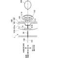
表示装置1は、コンバイナ2と虚像光源ユニット3と実像表示部4と制御部5(図8参照)とを、備えている。コンバイナ2は、虚像光源ユニット3からの光140(図3、図4参照)を目視者としての車両の運転者200の側に反射させることにより、コンバイナ2の前方に表示像39の虚像35を結像させる、虚像結像部材である。すなわちコンバイナ2は、運転者200にコンバイナ2を透して虚像35を視認させる、光学部材である。そこで本実施形態のコンバイナ2は、運転者200の前方視野内において虚像光源ユニット3からの光140の進路である光路上に、配置されている。それと共にコンバイナ2は、コンバイナ2を透してコンバイナ2の前方風景も視認可能に構成されている。
The display device 1 includes a combiner 2, a virtual image light source unit 3, a real image display unit 4, and a control unit 5 (see FIG. 8). The combiner 2 reflects the light 140 (see FIGS. 3 and 4) from the virtual image light source unit 3 toward the driver 200 of the vehicle as a viewer so that the virtual image 35 of the display image 39 is displayed in front of the combiner 2. A virtual image forming member that forms an image. That is, the combiner 2 is an optical member that allows the driver 200 to visually recognize the virtual image 35 through the combiner 2. Therefore, the combiner 2 of the present embodiment is disposed on the optical path that is the path of the light 140 from the virtual image light source unit 3 within the driver's 200 front view. At the same time, the combiner 2 is configured so that the front scenery of the combiner 2 can be seen through the combiner 2.
具体的にコンバイナ2は、虚像光源ユニット3からの光140の一部を反射すると共に、コンバイナ2の前方からの光の一部を透過して運転者200の眼201に到達させるハーフミラーとして構成されている。こうしたコンバイナ2は、例えばアクリル、ポリカーボネート等の透明樹脂を基材として、当該基材の虚像光源ユニット3側に規定される入射面21がハーフミラーコート(換言すればビームスプリッターコート)で被覆された構造に、形成される。
Specifically, the combiner 2 is configured as a half mirror that reflects a part of the light 140 from the virtual image light source unit 3 and transmits a part of the light from the front of the combiner 2 to reach the eyes 201 of the driver 200. Has been. In such a combiner 2, for example, a transparent resin such as acrylic or polycarbonate is used as a base material, and the incident surface 21 defined on the virtual image light source unit 3 side of the base material is covered with a half mirror coat (in other words, a beam splitter coat). Formed into a structure.
コンバイナ2は、インパネ上面部101における手前側部101aと奥側部101bとの境界付近に、設けられている。本実施形態ではコンバイナ2は、インパネ上面部101に常時起立した状態に取り付けられる取付部22(図7参照)を、下部に有している。これら取付部22とインパネ上面部101との取り付け方法は、例えばネジ、爪嵌合等、どのような方法でも良い。なお、コンバイナ2は不使用時には、インストルメントパネル100内に格納可能又はインパネ上面部101に伏せた状態となるように移動可能に、設けられていても良い。
The combiner 2 is provided in the vicinity of the boundary between the front side portion 101a and the back side portion 101b in the instrument panel upper surface portion 101. In the present embodiment, the combiner 2 has a mounting portion 22 (see FIG. 7) attached to the instrument panel upper surface portion 101 in a state where it always stands up. The attachment part 22 and the instrument panel upper surface part 101 may be attached by any method such as screwing or claw fitting. Note that the combiner 2 may be provided so that it can be stored in the instrument panel 100 or can be moved so as to be faced down on the instrument panel upper surface 101 when not in use.
コンバイナ2は、例えば長方形の板状に形成されている。コンバイナ2は、一方の長方形面が車両後方(すなわち運転者200側及び虚像光源ユニット3側)に向き、他方の長方形面が車両前方を向くように、配置される。このとき、コンバイナ2の長方形面の長手方向は、車両左右方向に向けられる。また、図1の正面又は図2の上面から見たときに、コンバイナ2の長手方向における中心(以下、コンバイナ中心という)は運転席又はステアリング110の左右方向における中心と位置合わせされ、当該コンバイナ中心での法線は車両左右方向を向いた平面(以下、左右中心面という)130上に位置する。すなわち、コンバイナ中心と左右中心面130との車両左右方向におけるズレ量は、0である。
The combiner 2 is formed in a rectangular plate shape, for example. The combiner 2 is arranged such that one rectangular surface faces the vehicle rear (that is, the driver 200 side and the virtual image light source unit 3 side), and the other rectangular surface faces the vehicle front. At this time, the longitudinal direction of the rectangular surface of the combiner 2 is directed to the vehicle left-right direction. When viewed from the front of FIG. 1 or the top surface of FIG. 2, the center in the longitudinal direction of the combiner 2 (hereinafter referred to as the combiner center) is aligned with the center in the left-right direction of the driver's seat or the steering 110, and The normal line at is located on a plane (hereinafter referred to as a left-right central plane) 130 facing the left-right direction of the vehicle. That is, the amount of deviation in the vehicle left-right direction between the combiner center and the left-right center plane 130 is zero.
さらに、コンバイナ2のインパネ上面部101からの起立角度θ1(図4参照)は、運転者200側に向いたコンバイナ2の入射面21に、虚像光源ユニット3からの光140が入射可能であり、かつ、当該入射光140が運転者200の眼201の方向に反射されるように、調整されている。
Further, the rising angle θ1 (see FIG. 4) from the instrument panel upper surface portion 101 of the combiner 2 allows the light 140 from the virtual image light source unit 3 to be incident on the incident surface 21 of the combiner 2 facing the driver 200 side. In addition, the incident light 140 is adjusted so as to be reflected toward the eyes 201 of the driver 200.
本実施形態のコンバイナ2は、虚像光源ユニット3の表示像39(図4参照)と同じ大きさの虚像35を結像するように、構成されている。すなわち、表示像39に対する虚像35の大きさの比は1.0倍となっている。拡大機能を有しないコンバイナ2においては、例えばコンバイナ2の入射面21とその反対側の面とは平面となっており、入射面21とその反対側の面との間の板厚はどの部位において同じ値となっている。
The combiner 2 of the present embodiment is configured to form a virtual image 35 having the same size as the display image 39 (see FIG. 4) of the virtual image light source unit 3. That is, the ratio of the size of the virtual image 35 to the display image 39 is 1.0. In the combiner 2 that does not have an enlargement function, for example, the incident surface 21 of the combiner 2 and the opposite surface thereof are flat, and the plate thickness between the incident surface 21 and the opposite surface is at any part. It is the same value.
虚像光源ユニット3は、虚像35を表示するための表示像39の光140を出射する。図4に示すように虚像光源ユニット3は、複数の光源31と、光源31を実装する基板32と、光源31及び基板32を収容する収容部33と、光源31の上方を覆うように設けられて光源31からの光を拡散して出射する拡散板34とを、有する。光源31は、例えばLED(Light Emitting Diode:発光ダイオード)である。光源31の発光色は例えば白色であるが、白色以外の色であっても良い。各光源31は、図5に示すように一直線上に配置される。
The virtual image light source unit 3 emits light 140 of a display image 39 for displaying the virtual image 35. As shown in FIG. 4, the virtual image light source unit 3 is provided so as to cover a plurality of light sources 31, a substrate 32 on which the light sources 31 are mounted, a housing portion 33 that houses the light sources 31 and the substrate 32, and the light source 31. And a diffusion plate 34 that diffuses and emits light from the light source 31. The light source 31 is, for example, an LED (Light Emitting Diode). The light emission color of the light source 31 is, for example, white, but may be a color other than white. Each light source 31 is arranged on a straight line as shown in FIG.
収容部33は、遮光性を有する材質(例えば不透明樹脂)により形成されて、光源31及び基板32の上方以外の周囲を囲むように設けられる。収容部33は、光源31を実装した基板32が取り付けられる底部33aと、当該底部33aに対向した位置の開口部33bと、底部33aと開口部33bの間の空間を取り囲む側壁部33cとを、有する。図4、図5に示すように開口部33bは、複数の光源31の配列方向を長手方向とする細長い長方形状に形成、すなわち直線状に形成されている。
The accommodating portion 33 is formed of a light-shielding material (for example, opaque resin) and is provided so as to surround the periphery of the light source 31 and the substrate 32 other than the upper portion. The accommodating portion 33 includes a bottom portion 33a to which the substrate 32 on which the light source 31 is mounted is attached, an opening portion 33b at a position facing the bottom portion 33a, and a side wall portion 33c that surrounds a space between the bottom portion 33a and the opening portion 33b. Have. As shown in FIGS. 4 and 5, the opening 33 b is formed in an elongated rectangular shape whose longitudinal direction is the arrangement direction of the plurality of light sources 31, that is, in a linear shape.
拡散板34は、開口部33bと同様の形状に形成されて、開口部33bに嵌められている。拡散板34は、光源31の光を拡散しつつ透過可能な材質(例えば乳白色の半透明樹脂)にて形成されている。
The diffusion plate 34 is formed in the same shape as the opening 33b and is fitted in the opening 33b. The diffusion plate 34 is formed of a material that can transmit light from the light source 31 while diffusing the light (for example, milky white translucent resin).
このように虚像光源ユニット3は、拡散板34の出射面34aを表示像39の形成面として、当該表示像39の光140を出射する発光部となっている。この表示像39は、正面から見ると細長い長方形状である。
As described above, the virtual image light source unit 3 is a light emitting unit that emits the light 140 of the display image 39 by using the emission surface 34 a of the diffusion plate 34 as the formation surface of the display image 39. The display image 39 has an elongated rectangular shape when viewed from the front.
図2〜図4に示すように虚像光源ユニット3は、インパネ上面部101に配置されている。詳しくは虚像光源ユニット3は、インパネ上面部101のうち、運転者200から見てコンバイナ2及び実像表示部4よりも手前側において、すなわち運転者200の側においてコンバイナ2に向けて光140を出射するように、配置されている。別の言い方をすると、虚像光源ユニット3は、インパネ上面部101のうち、車両の接地面に垂直な方向である車両高さ方向において実像表示部4及びステアリングコラム111よりも高い位置に、配置されている。また虚像光源ユニット3は、運転者200から見てステアリング110よりも奥側(すなわち車両前方側)に、配置されている。このように虚像光源ユニット3は、ステアリングコラム111の根元部の上辺りに配置されている。
As shown in FIGS. 2 to 4, the virtual image light source unit 3 is arranged on the instrument panel upper surface portion 101. Specifically, the virtual image light source unit 3 emits light 140 toward the combiner 2 on the front side of the combiner 2 and the real image display unit 4 when viewed from the driver 200, that is, on the driver 200 side, in the instrument panel upper surface portion 101. To be arranged. In other words, the virtual image light source unit 3 is disposed at a position higher than the real image display unit 4 and the steering column 111 in the vehicle height direction, which is a direction perpendicular to the grounding surface of the vehicle, on the instrument panel upper surface portion 101. ing. Further, the virtual image light source unit 3 is disposed on the back side (that is, the vehicle front side) from the steering 110 as viewed from the driver 200. As described above, the virtual image light source unit 3 is disposed around the upper portion of the root portion of the steering column 111.
インストルメントパネル100には、虚像光源ユニット3を支持する支持部103(図4参照)が設けられている。本実施形態では支持部103は、実像表示部4の設置面であるインパネ上面部101よりも高い位置に設けられているが、当該インパネ上面部101より低い位置に設けられていても良い。支持部103には、虚像光源ユニット3の収容部33となる凹部が形成されている。
The instrument panel 100 is provided with a support portion 103 (see FIG. 4) that supports the virtual image light source unit 3. In the present embodiment, the support portion 103 is provided at a position higher than the instrument panel upper surface portion 101 that is the installation surface of the real image display portion 4, but may be provided at a position lower than the instrument panel upper surface portion 101. The support portion 103 is formed with a recess serving as the housing portion 33 of the virtual image light source unit 3.
図2、図5に示すように虚像光源ユニット3は、左右中心面130の位置に配置されている。すなわち、虚像光源ユニット3(光源31、拡散板34)と左右中心面130との車両左右方向におけるズレ量は、0となっている。また、表示像39と左右中心面130との成す角度は、0°となっている。
As shown in FIGS. 2 and 5, the virtual image light source unit 3 is arranged at the position of the left and right central plane 130. That is, the amount of deviation between the virtual image light source unit 3 (the light source 31 and the diffuser plate 34) and the left and right center plane 130 in the vehicle left-right direction is zero. The angle formed between the display image 39 and the left and right central plane 130 is 0 °.
さらに虚像光源ユニット3は、運転者200から見て奥行方向に表示像39を寝かせた虚像35が結像されるように傾けて、配置されている。以下、図6を参照して、虚像光源ユニット3の配置角度の詳細を説明する。虚像光源ユニット3からの光140は、コンバイナ2の入射面21において反射される。このとき、光140の入射面21での反射角度θ3は、光140の入射面21への入射角度θ2と等しい。反射角度θ3にて反射された光141が運転者200の眼201に到達することで、コンバイナ2の前方に虚像35が結像されて視認される。この虚像35の結像位置は、反射光141をコンバイナ2に対して反対側に延長した線142上にて、虚像光源ユニット3から入射面21までの光学距離(光140の光路長)に応じた位置となる。このとき、虚像光源ユニット3から入射面21までの光学距離が大きいほど、コンバイナ2から離れた位置に虚像35が結像される。
Furthermore, the virtual image light source unit 3 is disposed so as to be tilted so that a virtual image 35 in which the display image 39 is laid in the depth direction as viewed from the driver 200 is formed. Hereinafter, the details of the arrangement angle of the virtual image light source unit 3 will be described with reference to FIG. Light 140 from the virtual image light source unit 3 is reflected on the incident surface 21 of the combiner 2. At this time, the reflection angle θ3 of the light 140 on the incident surface 21 is equal to the incident angle θ2 of the light 140 on the incident surface 21. When the light 141 reflected at the reflection angle θ3 reaches the eyes 201 of the driver 200, a virtual image 35 is formed in front of the combiner 2 and is visually recognized. The imaging position of the virtual image 35 depends on the optical distance (the optical path length of the light 140) from the virtual image light source unit 3 to the incident surface 21 on a line 142 obtained by extending the reflected light 141 on the opposite side with respect to the combiner 2. It becomes the position. At this time, the virtual image 35 is formed at a position farther from the combiner 2 as the optical distance from the virtual image light source unit 3 to the incident surface 21 is larger.
ここで、表示像39の各部間でコンバイナ2までの光学距離が等しくなる位置(以下、等距離位置という)30に虚像光源ユニット3が配置された場合、すなわち虚像光源ユニット3の表示像39を形成する出射面34aがコンバイナ2の入射面21に平行に配置された場合を、考える。この場合の虚像350は、表示像39の各部間でコンバイナ2までの光学距離が等しいことから、コンバイナ2からの距離が各部間でほぼ同一となる位置に結像される。このとき虚像350は、運転者200からみて奥行方向に長さを有していない。換言すれば、表示像39の正面視形状(図5参照)がそのまま虚像350として表示されてしまう。
Here, when the virtual image light source unit 3 is disposed at a position (hereinafter referred to as an equidistant position) 30 where the optical distances to the combiner 2 are equal between the parts of the display image 39, that is, the display image 39 of the virtual image light source unit 3 is displayed. Consider a case where the exit surface 34 a to be formed is arranged in parallel to the entrance surface 21 of the combiner 2. In this case, since the optical distance to the combiner 2 is equal between the respective parts of the display image 39, the virtual image 350 is formed at a position where the distance from the combiner 2 is substantially the same between the respective parts. At this time, the virtual image 350 does not have a length in the depth direction when viewed from the driver 200. In other words, the front view shape (see FIG. 5) of the display image 39 is displayed as it is as the virtual image 350.
そこで、本実施形態の虚像光源ユニット3は、表示像39を奥行方向に寝かせた形状の虚像35が結像されるように、表示像39を形成する出射面34aを等距離位置30に対して傾けて、配置されている。詳しくは虚像光源ユニット3は、表示像39と左右中心面130との成す角度を0°に維持しつつ(図5参照)、細長長方形状の表示像39の一端から他端側に向かうにしたがって次第にコンバイナ2までの光学距離が大きくなるように、等距離位置30に対して奥行方向の反対方向に傾けられている。このとき表示像39の光140のうち、入射面21においてインパネ上面部101からの高さが高い位置に入射する光ほど、光学距離を大きくする。図6の例では、虚像光源ユニット3を等距離位置30に配置した場合の出射面34aの下側端部を基点として、出射面34aを運転者200側に傾けている。
Therefore, in the virtual image light source unit 3 of the present embodiment, the emission surface 34a that forms the display image 39 is formed with respect to the equidistant position 30 so that a virtual image 35 having a shape in which the display image 39 is laid in the depth direction is formed. Tilt and arranged. Specifically, the virtual image light source unit 3 maintains the angle formed by the display image 39 and the left and right center plane 130 at 0 ° (see FIG. 5), and moves from one end of the elongated rectangular display image 39 toward the other end. The optical distance to the combiner 2 is gradually inclined with respect to the equidistant position 30 in the direction opposite to the depth direction. At this time, out of the light 140 of the display image 39, the light incident on the incident surface 21 at a position where the height from the instrument panel upper surface portion 101 is higher is increased. In the example of FIG. 6, the emission surface 34 a is inclined toward the driver 200 with the lower end of the emission surface 34 a when the virtual image light source unit 3 is disposed at the equidistant position 30 as a base point.
虚像光源ユニット3を等距離位置30に対して角度θ4だけ傾けたとすると、虚像35は、虚像光源ユニット3を等距離位置30に配置した場合の虚像350の結像位置に対して、角度θ4に相当する角度θ5だけ奥行方向に傾く。ここで、図1〜図4に示すように本実施形態では、実像表示部4が表示する実像45の延長線131上に伸びて虚像35が結像されるように、虚像光源ユニット3の傾きの角度θ4は設定されている。なお、実像表示部4が配置されるインパネ上面部101の手前側部101aは、奥側に向かうにしたがって次第に高くなるように若干の傾きがつけられているので、実像表示部4により表示される実像45の延長線131も、車両の接地面に対して若干の傾きを有している。故に、延長線131上にて結像される虚像35も、車両の接地面に対して若干の傾きを有している。
Assuming that the virtual image light source unit 3 is tilted by an angle θ4 with respect to the equidistant position 30, the virtual image 35 is at an angle θ4 with respect to the imaging position of the virtual image 350 when the virtual image light source unit 3 is disposed at the equidistant position 30. It tilts in the depth direction by a corresponding angle θ5. Here, as shown in FIGS. 1 to 4, in this embodiment, the inclination of the virtual image light source unit 3 so that the virtual image 35 is formed on the extension line 131 of the real image 45 displayed by the real image display unit 4. The angle θ4 is set. Note that the front side portion 101a of the instrument panel upper surface portion 101 on which the real image display unit 4 is arranged is slightly inclined so as to gradually increase toward the back side, so that it is displayed by the real image display unit 4. The extension line 131 of the real image 45 also has a slight inclination with respect to the ground contact surface of the vehicle. Therefore, the virtual image 35 formed on the extension line 131 also has a slight inclination with respect to the ground contact surface of the vehicle.
なお、運転者200が変わると、眼201の高さが変わることで、虚像35の結像位置は若干変わってくる。そこで、虚像光源ユニット3の位置やコンバイナ2の起立角度θ1を運転者200の操作に基づき微調整する調整機構を設けることで、虚像35の結像位置を微調整できるようにしても良い。
Note that when the driver 200 changes, the height of the eye 201 changes, so that the imaging position of the virtual image 35 changes slightly. Therefore, an image forming position of the virtual image 35 may be finely adjusted by providing an adjustment mechanism for finely adjusting the position of the virtual image light source unit 3 and the rising angle θ1 of the combiner 2 based on the operation of the driver 200.
本実施形態の虚像35は、実像45の延長線131上に沿って直線状に伸びる奥行方向に、長さを有している。ここで、虚像光源ユニット3(表示像39)の長手方向における長さが長いほど、虚像35の奥行方向における長さが長くなる。虚像35が奥行方向に長くなるほど、虚像35における奥側の端部35d(図1、図4参照)が現実に見える前方風景に近づくため、虚像35を見る際の運転者200の視線移動が抑えられて視認性が向上する。一方で、虚像光源ユニット3が大きくなると、虚像光源ユニット3の設置スペースの確保が困難となる。よって、虚像光源ユニット3の大きさは、虚像35の視認性と、虚像光源ユニット3の設置スペースとの観点から定められる。
The virtual image 35 of the present embodiment has a length in the depth direction extending linearly along the extension line 131 of the real image 45. Here, the longer the length of the virtual image light source unit 3 (display image 39) in the longitudinal direction, the longer the length of the virtual image 35 in the depth direction. The longer the virtual image 35 is in the depth direction, the closer the end 35d (see FIGS. 1 and 4) of the virtual image 35 is to the frontal scenery where the virtual image 35 can be seen. Visibility is improved. On the other hand, when the virtual image light source unit 3 is large, it is difficult to secure a space for installing the virtual image light source unit 3. Therefore, the size of the virtual image light source unit 3 is determined from the viewpoint of the visibility of the virtual image 35 and the installation space of the virtual image light source unit 3.
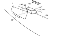
虚像光源ユニット3及びこれを支持する支持部103は、フード120によって運転者200からは目視できないように配置されている。このフード120は、遮光性を有する例えば樹脂により形成されている。またフード120は、コンバイナ2の方向以外は遮光壁としての各部121〜123により虚像光源ユニット3の周囲を囲む形状に、形成されている。詳しくはフード120は、図3、図4に示すように、運転者200の側に向いた正面部121と、虚像光源ユニット3の上方を覆うように設けられる上面部122とを、有する。これら正面部121及び上面部122は、板状に形成されている。
The virtual image light source unit 3 and the support portion 103 that supports the virtual image light source unit 3 are arranged so that they cannot be seen by the driver 200 by the hood 120. The hood 120 is made of, for example, a resin having a light shielding property. The hood 120 is formed in a shape surrounding the virtual image light source unit 3 by the respective parts 121 to 123 as light shielding walls except for the direction of the combiner 2. Specifically, as shown in FIGS. 3 and 4, the hood 120 includes a front surface portion 121 facing the driver 200 and an upper surface portion 122 provided to cover the virtual image light source unit 3. The front part 121 and the upper surface part 122 are formed in a plate shape.
正面部121は、インストルメントパネル100の前面部102と一体に形成されており、前面部102のうち左右方向における中央部(左右中心面130が交差する部分)の上端から上方に延設されている。正面部121は、上方に向かうにつれて次第に左右幅が小さくなる形状、すなわち台形に形成されている。
The front part 121 is formed integrally with the front part 102 of the instrument panel 100 and extends upward from the upper end of the central part (the part where the left and right central planes 130 intersect) of the front part 102 in the left-right direction. Yes. The front part 121 is formed in a shape in which the lateral width gradually decreases as it goes upward, that is, in a trapezoidal shape.
上面部122は、正面部121の上端から奥行方向に突出するように、設けられている。上面部122の正面部121からの突出量は、運転者200から虚像光源ユニット3は目視できずかつ実像表示部4は目視できるように、設定されている。これにより上面部122の先端122aは、図4、図7に示すように虚像光源ユニット3よりも奥側にて位置するが、実像表示部4よりも手前側に位置する。また上面部122は、上面視で略長方形状に形成されている。以上の正面部121及び上面部122は、インストルメントパネル100の前面部102に一体に形成されているが、別体に形成されていても良い。
The upper surface part 122 is provided so as to protrude in the depth direction from the upper end of the front part 121. The amount of protrusion of the upper surface part 122 from the front part 121 is set so that the virtual image light source unit 3 cannot be seen from the driver 200 and the real image display part 4 can be seen. As a result, the front end 122a of the upper surface portion 122 is positioned on the back side of the virtual image light source unit 3 as shown in FIGS. 4 and 7, but is positioned on the near side of the real image display unit 4. The upper surface portion 122 is formed in a substantially rectangular shape when viewed from above. The front portion 121 and the upper surface portion 122 described above are formed integrally with the front surface portion 102 of the instrument panel 100, but may be formed separately.
さらにフード120は、図7に示すように、正面部121及び上面部122で囲まれた空間において車両左右方向に間隔をあけて配置された2つの側面部123を、有する。側面部123は、板状に形成されている。側面部123では、高さ方向の一端が上面部122に接続され、他端がインパネ上面部101に接続されている。側面部123の前後方向における一端は、正面部121に接続されている。加えてフード120は、コンバイナ2の方向には遮光壁が設けられておらず、コンバイナ2の方向に開口を有する。
Furthermore, as shown in FIG. 7, the hood 120 includes two side surface portions 123 that are arranged at intervals in the left-right direction of the vehicle in a space surrounded by the front surface portion 121 and the upper surface portion 122. The side surface portion 123 is formed in a plate shape. In the side surface portion 123, one end in the height direction is connected to the upper surface portion 122, and the other end is connected to the instrument panel upper surface portion 101. One end of the side surface portion 123 in the front-rear direction is connected to the front surface portion 121. In addition, the hood 120 is not provided with a light shielding wall in the direction of the combiner 2, and has an opening in the direction of the combiner 2.
このようにフード120は、インパネ上面部101においてコンバイナ2の方向に開口を有し、コンバイナ2の方向以外の方向は閉塞した形状を有する。虚像光源ユニット3及びこれの支持部103は、図4に示すように正面部121、上面部122及び2つの側面部123で囲まれた空間124に、配置される。この空間124は、運転者200から見ると目視不能な空間となっているが、コンバイナ2から見ると開いた空間となっている。これにより、運転者200からは虚像光源ユニット3を目視不能であるが、虚像光源ユニット3からの光140はコンバイナ2に到達可能となる。
As described above, the hood 120 has an opening in the direction of the combiner 2 in the instrument panel upper surface portion 101, and has a shape closed in directions other than the direction of the combiner 2. As shown in FIG. 4, the virtual image light source unit 3 and the support portion 103 thereof are disposed in a space 124 surrounded by a front surface portion 121, an upper surface portion 122, and two side surface portions 123. This space 124 is a space that is not visible when viewed from the driver 200, but is an open space when viewed from the combiner 2. Accordingly, the driver 200 cannot see the virtual image light source unit 3, but the light 140 from the virtual image light source unit 3 can reach the combiner 2.
ここで虚像光源ユニット3では、コンバイナ2より運転者200側において出射面34aがコンバイナ2の方向に向くように配置されて、出射面34aからの光140が反射鏡を介さないで直接にコンバイナ2に到達する。すなわち、虚像光源ユニット3とコンバイナ2の間には、虚像光源ユニット3からの光140の向きを変えて表示像39をコンバイナ2まで導く反射鏡は、図4、図6に示すように介在されていない。
Here, in the virtual image light source unit 3, the exit surface 34 a is arranged on the driver 200 side of the combiner 2 so as to face the combiner 2, and the light 140 from the exit surface 34 a is directly connected to the combiner 2 without passing through a reflecting mirror. To reach. That is, between the virtual image light source unit 3 and the combiner 2, a reflecting mirror that changes the direction of the light 140 from the virtual image light source unit 3 and guides the display image 39 to the combiner 2 is interposed as shown in FIGS. Not.
図1、図3、図4、図7に示すように実像表示部4は、車両前後方向であるインパネ上面部101の奥行方向に伸びた直線状の実像45を、表示する。実像表示部4は、虚像光源ユニット3と同様の構造を有している。具体的に実像表示部4は、図4に示すように、複数の光源41と、光源41を実装する基板42と、これら光源41、基板42を収容する遮光性の収容部43と、光源41の上方を覆うように設けられて光源41からの光を拡散して出射する拡散板44とを、有する。光源41は、例えばLEDである。光源41の発光色は、例えば虚像光源ユニット3の発光色と同一色(例えば白色)である。各光源41は、基板42上に一直線に配置される。
As shown in FIGS. 1, 3, 4, and 7, the real image display unit 4 displays a linear real image 45 extending in the depth direction of the instrument panel upper surface 101 that is the vehicle front-rear direction. The real image display unit 4 has the same structure as the virtual image light source unit 3. Specifically, as shown in FIG. 4, the real image display unit 4 includes a plurality of light sources 41, a substrate 42 on which the light sources 41 are mounted, a light-shielding accommodation unit 43 that accommodates the light sources 41 and the substrate 42, and a light source 41. And a diffusing plate 44 that diffuses and emits the light from the light source 41. The light source 41 is, for example, an LED. The emission color of the light source 41 is, for example, the same color (for example, white) as the emission color of the virtual image light source unit 3. Each light source 41 is arranged in a straight line on the substrate 42.
収容部43及び拡散板44は、虚像光源ユニット3の収容部33及び拡散板34と同様に形成されている。拡散板44の出射面44aは、実像表示部4で表示する実像45を、形成する。
The accommodating portion 43 and the diffusing plate 44 are formed in the same manner as the accommodating portion 33 and the diffusing plate 34 of the virtual image light source unit 3. The exit surface 44 a of the diffusion plate 44 forms a real image 45 that is displayed on the real image display unit 4.
実像表示部4は、運転者200から目視可能な位置に配置されている。具体的に実像表示部4は、運転者200の前方視野内となるインパネ上面部101の手前側部101aに、配置されている。詳しくは手前側部101aには、実像表示部4の収容部43を構成する凹部が形成されており、光源41、基板42及び拡散板44は当該凹部に嵌められている。実像表示部4において実像45を形成する出射面44aは、インパネ上面部101の手前側部101aと同一平面に設けられるが、手前側部101aより若干凹んだ位置又は若干突出した位置に設けられていても良い。
The real image display unit 4 is disposed at a position where the driver 200 can see the real image display unit 4. Specifically, the real image display unit 4 is disposed on the front side portion 101 a of the instrument panel upper surface portion 101 that is in the front visual field of the driver 200. Specifically, the front side portion 101a is formed with a concave portion constituting the accommodating portion 43 of the real image display portion 4, and the light source 41, the substrate 42 and the diffusion plate 44 are fitted into the concave portion. The exit surface 44a that forms the real image 45 in the real image display unit 4 is provided on the same plane as the front side portion 101a of the instrument panel upper surface portion 101, but is provided at a position slightly recessed or slightly protruding from the front side portion 101a. May be.
図1、図2に示すように実像表示部4は、左右中心面130の位置に配置されている。すなわち、実像表示部4が表示する細長長方形状の実像45と左右中心面130との成す角度は、0°となっている。
As shown in FIGS. 1 and 2, the real image display unit 4 is arranged at the position of the left and right central plane 130. That is, the angle formed between the elongated rectangular real image 45 displayed by the real image display unit 4 and the left and right central plane 130 is 0 °.
図1、図4に示すように実像表示部4(実像45)の奥側の端部44bは、コンバイナ2より手前側に配置されているが、虚像35と実像45とを一つの直線状画像として視認させるためには、できるだけコンバイナ2に近い位置に配置されるのが好ましい。なお、虚像35の手前側の端部35cとコンバイナ2との距離が大きい場合には、実像表示部4の端部44bは、コンバイナ2と同一位置又はコンバイナ2より奥側の位置まで延設されていても良い。これによって、実像45と虚像35との一体性及び連続性を確保しやすくできる。
As shown in FIGS. 1 and 4, the rear end 44 b of the real image display unit 4 (real image 45) is disposed on the front side of the combiner 2, but the virtual image 35 and the real image 45 are combined into one linear image. In order to make it visually recognizable, it is preferable to arrange it as close to the combiner 2 as possible. When the distance between the front end 35 c of the virtual image 35 and the combiner 2 is large, the end 44 b of the real image display unit 4 extends to the same position as the combiner 2 or to a position behind the combiner 2. May be. This makes it easy to ensure the integrity and continuity between the real image 45 and the virtual image 35.
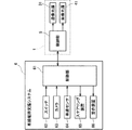
図8に示す制御部5は、各種処理を実行するCPU、CPUが実行する処理のプログラム等を記憶したROM、及びCPUの処理時に各種情報を一時的に記憶するRAM等から、構成されている。制御部5は、虚像光源ユニット3の光源31(虚像光源)及び実像表示部4の光源41(実像光源)の点灯を制御する。詳しくは車両には、図8に示すように車線維持支援システム6が搭載されており、制御部5は当該システム6の作動時に両光源31、41を点灯させ、システム6の停止時には両光源31、41を消灯させる。なお、制御部5は、例えばインストルメントパネル100内に設けられる。
The control unit 5 shown in FIG. 8 includes a CPU that executes various processes, a ROM that stores programs and the like of processes executed by the CPU, and a RAM that temporarily stores various information during the processing of the CPU. . The control unit 5 controls lighting of the light source 31 (virtual image light source) of the virtual image light source unit 3 and the light source 41 (real image light source) of the real image display unit 4. Specifically, as shown in FIG. 8, the vehicle is equipped with a lane keeping support system 6, and the control unit 5 lights both the light sources 31 and 41 when the system 6 operates, and both the light sources 31 when the system 6 is stopped. , 41 are turned off. The control unit 5 is provided in the instrument panel 100, for example.
ここで、車線維持支援システム6について説明する。車線維持支援システム6は、車両が高速走行中に運転者200によるステアリング110の操作が無くても自動で車線を維持するシステムである。車線維持支援システム6は、運転者200の操作により該システム6のオンオフを切り替えるスイッチ62、車両前方の風景を撮影するカメラ63、車速を検出する車速センサ64、車両の操舵機構を電動で作動させるステアリング装置65、自動の車線維持が困難な場合に運転者200に警告する警告装置66及びこれらと接続した制御部61等から、構成されている。
Here, the lane keeping support system 6 will be described. The lane keeping support system 6 is a system that automatically keeps the lane even when the driver 200 does not operate the steering 110 while the vehicle is traveling at a high speed. The lane keeping support system 6 electrically operates a switch 62 that switches on and off the system 6 by an operation of the driver 200, a camera 63 that captures a landscape in front of the vehicle, a vehicle speed sensor 64 that detects a vehicle speed, and a vehicle steering mechanism. A steering device 65, a warning device 66 that warns the driver 200 when it is difficult to maintain an automatic lane, and a control unit 61 and the like connected thereto are configured.
制御部61は、運転者200によるスイッチ62の操作によって車線維持支援システム6がオンとなり、かつ車速センサ64の検出する車速が所定値(例えば65km/h)以上となる場合に、カメラ63の撮影画像から道路の白線等の路面標示を認識し、当該路面標示により区切られる車線から逸脱しないよう、ステアリング装置65に操舵の自動制御を指令する。また制御部61は、車線のカーブ半径が急な場合等、自動の車線維持が困難な場合には、車線維持支援システム6の作動を停止する等の警告を、警告装置66に出力させる。
The control unit 61 captures the camera 63 when the lane keeping support system 6 is turned on by the operation of the switch 62 by the driver 200 and the vehicle speed detected by the vehicle speed sensor 64 is equal to or higher than a predetermined value (for example, 65 km / h). A road marking such as a white line on the road is recognized from the image, and an automatic steering control is commanded to the steering device 65 so as not to deviate from the lane delimited by the road marking. Further, the control unit 61 causes the warning device 66 to output a warning such as stopping the operation of the lane keeping support system 6 when automatic lane keeping is difficult, such as when the lane curve radius is steep.
なお、本実施形態の車線維持支援システム6では、当該システム6の作動時に、車両の加減速操作は運転者200が行うこととなっているが、車両の加減速も自動で行うようにしても良い。この場合に車両には、前方車両との距離を検出するセンサ(例えばカメラ、レーダ等)を搭載し、当該センサにより検出された前方車両との距離に応じて車両の駆動装置(例えばエンジン、モータ等)による加速や、車両のブレーキ装置による減速を制御する。
In the lane keeping support system 6 of the present embodiment, the driver 200 performs the acceleration / deceleration operation of the vehicle when the system 6 is operated. However, the acceleration / deceleration of the vehicle may be automatically performed. good. In this case, the vehicle is equipped with a sensor (for example, a camera, a radar, or the like) that detects the distance from the preceding vehicle, and a vehicle driving device (for example, an engine or a motor) according to the distance from the preceding vehicle detected by the sensor. Etc.) and deceleration by the vehicle brake device are controlled.
表示装置1の制御部5と車線維持支援システム6の制御部61とは、通信可能に接続されている。制御部5は、車線維持支援システム6の制御部61からシステム6の作動、停止の情報を受信し、当該受信情報に基づいて、両光源31、41の点灯、消灯を切り替える。
The control unit 5 of the display device 1 and the control unit 61 of the lane keeping support system 6 are connected to be communicable. The control unit 5 receives information on the operation and stop of the system 6 from the control unit 61 of the lane keeping support system 6 and switches on and off the light sources 31 and 41 based on the received information.
以下、本実施形態の効果を説明する。本実施形態によれば、表示像39の正面視形状をそのまま運転者200に見せるのではなく、当該形状を奥行方向に寝かせて虚像表示する。すなわち、現実の奥行方向の空間に長さを有した表示が行われるので、従来の疑似的な奥行き表現に比べて、奥行き感を出すことが可能となる。
Hereinafter, the effect of this embodiment will be described. According to this embodiment, the front view shape of the display image 39 is not shown to the driver 200 as it is, but the shape is laid down in the depth direction and a virtual image is displayed. That is, since a display having a length in the actual space in the depth direction is performed, it is possible to give a sense of depth compared to the conventional pseudo depth expression.
また、実像表示部4による実像45と、虚像光源ユニット3及びコンバイナ2による虚像35とは、車線維持支援システム6の作動時に表示され、かつ運転者200の前方奥行方向に直線状に表示される。故に、運転者200には実像45及び虚像35を道路の車線を表す路面標示として想起させることができ、車線維持支援システム6によって自動で車線維持が行われていることを運転者200に容易に把握させることができる。
In addition, the real image 45 by the real image display unit 4 and the virtual image 35 by the virtual image light source unit 3 and the combiner 2 are displayed when the lane keeping support system 6 is operated, and are displayed linearly in the forward depth direction of the driver 200. . Therefore, the driver 200 can be reminded of the real image 45 and the virtual image 35 as road markings representing the lanes of the road, and it is easy for the driver 200 that the lane maintenance is automatically performed by the lane maintenance support system 6. It can be grasped.
また、実像45及び虚像35は同一直線上に表示されるので、運転者200には実像45と虚像35とを連続性及び一体性のある像として認識させることができる。なお、ここでいう連続性及び一体性とは、実像45と虚像35との間に若干の隙間を有している場合も含む意味で、用いている。
Since the real image 45 and the virtual image 35 are displayed on the same straight line, the driver 200 can recognize the real image 45 and the virtual image 35 as images having continuity and integrity. Here, the terms “continuity” and “integration” are used to include a case where there is a slight gap between the real image 45 and the virtual image 35.
また、実像45及び虚像35は共に現実の奥行空間に長さを有しているので、3次元をグラフィックで模した疑似的な奥行表現に比べて、奥行き感を出すことができ、車両は車線に沿って走行していることを運転者200に認識させやすくできる。
In addition, since both the real image 45 and the virtual image 35 have a length in the actual depth space, it is possible to give a sense of depth as compared to a pseudo depth expression imitating a three-dimensional graphic. The driver 200 can easily recognize that the vehicle is traveling along the road.
また、実像45と虚像35とを組み合わせて奥行き表現をするので、実像45と虚像35のどちらか一方のみに比べて、より奥行方向に長い表示が可能となる。すなわち、実像45だけで奥行き表現をしようとすると、インパネ上面部101の奥行幅以上の長さの表示はできない。また一方、虚像35だけで奥行き表現をしようとすると、奥行方向により長い虚像35を結像させるためには、虚像光源ユニット3やコンバイナ2が大きくなってしまう。さらに、虚像35だけで奥行き表現をしようとすると、コンバイナ2の手前側の奥行き表現ができない。これらに対して本実施形態では、実像45と虚像35とを組み合わせることで、虚像光源ユニット3やコンバイナ2を大きくしなくても、奥行方向に長い表示が可能となる。
Further, since the depth representation is performed by combining the real image 45 and the virtual image 35, it is possible to display longer in the depth direction than only one of the real image 45 and the virtual image 35. In other words, if the depth is expressed only by the real image 45, it is not possible to display a length longer than the depth of the instrument panel upper surface 101. On the other hand, if an attempt is made to express the depth only with the virtual image 35, the virtual image light source unit 3 and the combiner 2 become large in order to form a longer virtual image 35 in the depth direction. Furthermore, if the depth is expressed only by the virtual image 35, the depth on the near side of the combiner 2 cannot be expressed. On the other hand, in the present embodiment, by combining the real image 45 and the virtual image 35, it is possible to perform a long display in the depth direction without enlarging the virtual image light source unit 3 and the combiner 2.
また、虚像光源ユニット3からの光140は、反射鏡を介さないで直接にコンバイナ2に入射するので、反射鏡のない分、表示装置1の構成を簡素にでき、表示装置1が大型化するのを抑制できる。
In addition, since the light 140 from the virtual image light source unit 3 is directly incident on the combiner 2 without passing through a reflecting mirror, the configuration of the display device 1 can be simplified and the display device 1 is enlarged because there is no reflecting mirror. Can be suppressed.
また、虚像光源ユニット3はインパネ上面部101に配置されているので、インストルメントパネル100内の構成を簡素にできる。さらに、インストルメントパネル100内に虚像光源ユニット3を配置した構成では、当該ユニット3からの光を出射するための穴をインパネ上面部101に設ける必要があるが、本実施形態では虚像光源ユニット3がインパネ上面部101の外側に配置されているので、インパネ上面部101に穴をあける必要がなく、インストルメントパネル100の意匠性、すなわち見た目を向上できる。
Further, since the virtual image light source unit 3 is disposed on the instrument panel upper surface portion 101, the configuration in the instrument panel 100 can be simplified. Furthermore, in the configuration in which the virtual image light source unit 3 is arranged in the instrument panel 100, it is necessary to provide a hole for emitting light from the unit 3 in the instrument panel upper surface portion 101. In the present embodiment, the virtual image light source unit 3 Is disposed outside the instrument panel upper surface portion 101, so that it is not necessary to make a hole in the instrument panel upper surface portion 101, and the design of the instrument panel 100, that is, the appearance can be improved.
また、実像45及び虚像35はフロントウィンドウ105より低い位置に表示されるが、実像45及び虚像35の表示位置は奥側に向かうにしたがって次第に高くなるので、視線をそれほど下に動かさなくても実像45及び虚像35を視認できる。故に、実像45及び虚像35の視認性を向上できる。
The real image 45 and the virtual image 35 are displayed at a position lower than the front window 105, but the display positions of the real image 45 and the virtual image 35 gradually increase toward the back side, so that the real image can be obtained without moving the line of sight down so much. 45 and the virtual image 35 can be visually recognized. Therefore, the visibility of the real image 45 and the virtual image 35 can be improved.
また、実像45及び虚像35はインストルメントパネル100の外側に表示されるので、インストルメントパネル100に設けられるメータ内に表示する場合に比べて、実像45及び虚像35を見る際の運転者200の視線移動を少なくでき、これにより実像45及び虚像35による直線像の視認性を向上できる。
Further, since the real image 45 and the virtual image 35 are displayed outside the instrument panel 100, the driver 200 when viewing the real image 45 and the virtual image 35 is compared with the case where the real image 45 and the virtual image 35 are displayed. The movement of the line of sight can be reduced, whereby the visibility of the straight line image by the real image 45 and the virtual image 35 can be improved.
また、コンバイナ2を透した前方風景の視認によれば、コンバイナ2の設置に伴う前方風景の視認性が低下するのを抑制できる。
Moreover, according to the visual recognition of the forward scenery through the combiner 2, it is possible to suppress the visibility of the forward scenery associated with the installation of the combiner 2 from being lowered.
また、虚像光源ユニット3はコンバイナ2の方向以外は遮光壁としての各部121〜123で囲まれているので、虚像光源ユニット3からの光140がコンバイナ2以外の方向に漏れてしまうのを抑制でき、当該光140を効率的にコンバイナ2に当てることができる。さらに、虚像光源ユニット3はフード120によって運転者200からは目視できないように配置されているので、インストルメントパネル100の見た目を向上できる。
Moreover, since the virtual image light source unit 3 is surrounded by the respective parts 121 to 123 as light shielding walls except for the direction of the combiner 2, it is possible to suppress the light 140 from the virtual image light source unit 3 from leaking in the direction other than the combiner 2. The light 140 can be efficiently applied to the combiner 2. Furthermore, since the virtual image light source unit 3 is disposed by the hood 120 so that it cannot be seen by the driver 200, the appearance of the instrument panel 100 can be improved.
(第2実施形態)
次に本発明の第2実施形態を、上記実施形態と異なる部分を中心に説明する。図9に示す本実施形態のコンバイナ2は、虚像光源ユニット3の表示像39を拡大するレンズ機能を、有している。詳しくは、コンバイナ2の入射面21の全部が凹曲面に形成されている。すなわちコンバイナ2は、高さ方向に沿って中心に近づくにつれて次第に入射面21とその反対側の面との間の板厚が小さくなり、かつコンバイナ2の左右方向に沿って中心に近づくにつれて次第に板厚が小さくなる形状に、形成されている。
(Second Embodiment)
Next, a second embodiment of the present invention will be described focusing on differences from the above embodiment. The combiner 2 of this embodiment shown in FIG. 9 has a lens function that enlarges the display image 39 of the virtual image light source unit 3. Specifically, the entire incident surface 21 of the combiner 2 is formed in a concave curved surface. That is, as the combiner 2 approaches the center along the height direction, the plate thickness between the incident surface 21 and the opposite surface gradually decreases, and the plate gradually increases as it approaches the center along the left-right direction of the combiner 2. It is formed in a shape with a reduced thickness.
凹曲面の入射面21を有したコンバイナ2は、レンズの機能を有し、表示像39を拡大した虚像35を結像させる。これにより、図9の虚像35の奥行方向における長さは、第1実施形態の図4の虚像35の奥行方向における長さよりも長くなる。また、図9の虚像35の手前側(すなわち運転者200側)の端部35cは、図4の虚像35における手前側の端部35cよりもコンバイナ2に近い位置に、結像されることになる。それと共に、図9の虚像35の奥側の端部35dは、図1、図4の虚像35における奥側の端部35dよりもコンバイナ2から離れた位置に、結像されることになる。
The combiner 2 having the concave incident surface 21 has a lens function and forms a virtual image 35 in which the display image 39 is enlarged. Thereby, the length in the depth direction of the virtual image 35 in FIG. 9 is longer than the length in the depth direction of the virtual image 35 in FIG. 4 of the first embodiment. Further, the near end 35c of the virtual image 35 in FIG. 9 (that is, the driver 200 side) is formed at a position closer to the combiner 2 than the near end 35c in the virtual image 35 in FIG. Become. At the same time, the back end 35d of the virtual image 35 in FIG. 9 is imaged at a position farther from the combiner 2 than the back end 35d in the virtual image 35 in FIGS.
ここでコンバイナ2(入射面21)の曲率が大きいほど、表示像39の拡大率は大きくなる。よって、コンバイナ2の曲率は、虚像35をどの程度の大きさで表示させるのかに基づいて適宜に設定される。なお、コンバイナ2の曲率以外の構成は第1実施形態と同じである。
Here, the larger the curvature of the combiner 2 (incident surface 21) is, the larger the magnification of the display image 39 is. Therefore, the curvature of the combiner 2 is appropriately set based on how large the virtual image 35 is displayed. The configuration other than the curvature of the combiner 2 is the same as that of the first embodiment.
本実施形態によれば、第1実施形態と同様の効果が得られることに加えて、表示像39を拡大した虚像35が表示されるので、実像表示部4が表示する実像45の奥側の端部44bと、虚像35の手前側の端部35cとの間の隙間を、小さくできる。これによれば、より一層、実像45と虚像35とを連続した一体の画像として視認させやすくできる。
According to the present embodiment, in addition to obtaining the same effect as the first embodiment, the virtual image 35 obtained by enlarging the display image 39 is displayed, so that the rear side of the real image 45 displayed by the real image display unit 4 is displayed. A gap between the end 44b and the end 35c on the near side of the virtual image 35 can be reduced. According to this, the real image 45 and the virtual image 35 can be made easier to visually recognize as a continuous integrated image.
また、虚像35の奥側の端部35dをより奥側の位置に表示させることができるので、より一層、表示の奥行き感を出すことができる。
Moreover, since the end portion 35d on the back side of the virtual image 35 can be displayed at a deeper position, a sense of depth of display can be further increased.
また、虚像光源ユニット3やコンバイナ2を大きくしなくても、虚像35の奥行方向の長さを確保できる。故に、虚像光源ユニット3やコンバイナ2を小型化できる。
Further, the length of the virtual image 35 in the depth direction can be secured without increasing the size of the virtual image light source unit 3 and the combiner 2. Therefore, the virtual image light source unit 3 and the combiner 2 can be reduced in size.
(第3実施形態)
次に本発明の第3実施形態を、上記実施形態と異なる部分を中心に説明する。第2実施形態では、コンバイナ2の全体がレンズ機能を有する例を示したが、本実施形態ではコンバイナ2の一部のみにレンズ機能を持たせている。図10に示すように、本実施形態のコンバイナ2の入射面21では、一部が凹曲面に形成され、残余部が平坦面に形成されている。
(Third embodiment)
Next, a third embodiment of the present invention will be described focusing on the differences from the above embodiment. In the second embodiment, an example in which the entire combiner 2 has a lens function is shown. However, in this embodiment, only a part of the combiner 2 has a lens function. As shown in FIG. 10, in the entrance surface 21 of the combiner 2 of this embodiment, a part is formed in a concave curved surface, and the remainder part is formed in the flat surface.
凹曲面に形成された部分(以下、凹曲面部という)21aは、虚像光源ユニット3からの光140のうち虚像35の手前側の一部を形成する光が入射する位置に、形成されている。他方、虚像光源ユニット3からの光140のうち虚像35の手前側の一部を除く残余部(すなわち虚像35の奥側部)を形成する光が入射する位置には、凹曲面部21aは形成されておらず、平坦面21bが形成されている。
A portion (hereinafter referred to as a concave curved surface portion) 21a formed on the concave curved surface is formed at a position where light forming a part of the front side of the virtual image 35 of the light 140 from the virtual image light source unit 3 is incident. . On the other hand, the concave curved surface portion 21a is formed at a position where light forming the remaining portion (that is, the back side portion of the virtual image 35) excluding a portion of the light 140 from the virtual image light source unit 3 on the front side of the virtual image 35 is incident. The flat surface 21b is formed.
コンバイナ2は、凹曲面部21aのみがレンズ機能を有している。そのため、入射面21に入射した光140のうち、凹曲面部21aに入射する光が形成する像のみ拡大され、残りの光が形成する像は等倍表示される。よって、図10に示すように、虚像35の手前側の端部35cをよりコンバイナ2に近づけることができる。なお、凹曲面部21a以外の構成は上記実施形態と同じである。
In the combiner 2, only the concave curved surface portion 21a has a lens function. Therefore, among the light 140 incident on the incident surface 21, only the image formed by the light incident on the concave curved surface portion 21a is enlarged, and the image formed by the remaining light is displayed at the same magnification. Therefore, as shown in FIG. 10, the near end 35 c of the virtual image 35 can be brought closer to the combiner 2. The configuration other than the concave curved surface portion 21a is the same as that in the above embodiment.
本実施形態によれば、上記実施形態と同様の効果が得られることに加えて、虚像光源ユニット3やコンバイナ2を大きくしなくても、虚像35の手前側の端部35cをコンバイナ2に近づけることができる。よって、この端部35cと実像45の奥側の端部44bとの間の隙間を、小さくできる。これによれば、より一層、実像45と虚像35とが連続した一体の画像として視認させやすくできる。
According to this embodiment, in addition to obtaining the same effect as the above embodiment, the front end 35c of the virtual image 35 is brought closer to the combiner 2 without enlarging the virtual image light source unit 3 and the combiner 2. be able to. Therefore, the gap between the end portion 35c and the end portion 44b on the deep side of the real image 45 can be reduced. According to this, the real image 45 and the virtual image 35 can be made easier to visually recognize as a continuous integral image.
また、虚像35の奥側の部分は、虚像光源ユニット3の表示像39を等倍表示しているので、拡大により虚像35が歪んでしまうのを抑制できる。
Moreover, since the display image 39 of the virtual image light source unit 3 is displayed at an equal magnification in the back side portion of the virtual image 35, the virtual image 35 can be prevented from being distorted by enlargement.
(第4実施形態)
次に本発明の第4実施形態を、上記実施形態と異なる部分を中心に説明する。本実施形態では、第3実施形態と同様にコンバイナ2の入射面21の一部のみに凹曲面部21aが形成されるが、当該凹曲面部21aの形成位置が第3実施形態と異なっている。すなわち、図11に示すように本実施形態の凹曲面部21aは、虚像光源ユニット3からの光140のうち、虚像35の奥側の一部を形成する光が入射する位置に形成されている。それ以外の構成は第3実施形態と同じである。
(Fourth embodiment)
Next, a fourth embodiment of the present invention will be described focusing on the differences from the above embodiment. In the present embodiment, the concave curved surface portion 21a is formed on only a part of the incident surface 21 of the combiner 2 as in the third embodiment, but the formation position of the concave curved surface portion 21a is different from the third embodiment. . That is, as shown in FIG. 11, the concave curved surface portion 21 a of the present embodiment is formed at a position where light that forms a part of the back side of the virtual image 35 out of the light 140 from the virtual image light source unit 3 is incident. . The other configuration is the same as that of the third embodiment.
本実施形態によれば、上記実施形態と同様の効果が得られることに加えて、虚像光源ユニット3やコンバイナ2を大きくしなくても、虚像35の奥側の端部35dをより奥側の位置に表示させることができる。これによれば、より一層、表示の奥行き感を出すことができる。
According to this embodiment, in addition to obtaining the same effect as the above embodiment, the end portion 35d on the back side of the virtual image 35 can be placed on the back side without increasing the size of the virtual image light source unit 3 or the combiner 2. Can be displayed in the position. According to this, a sense of depth of display can be further increased.
また、虚像35の手前側の部分は、虚像光源ユニット3の表示像39を等倍表示しているので、拡大することにより虚像35が歪んでしまうのを抑制できる。
In addition, the portion on the near side of the virtual image 35 displays the display image 39 of the virtual image light source unit 3 at the same magnification, so that the virtual image 35 can be prevented from being distorted by being enlarged.
(第5実施形態)
次に本発明の第5実施形態を、上記実施形態と異なる部分を中心に説明する。図12、図13に本実施形態の表示装置を示す。本実施形態は、虚像光源ユニット3及び実像表示部4の配置位置が上記実施形態と異なっている。また、液晶ディスプレイ7が設けられている点でも上記実施形態と異なっている。それら以外の構成は上記実施形態と同じである。
(Fifth embodiment)
Next, a fifth embodiment of the present invention will be described focusing on the differences from the above embodiment. 12 and 13 show the display device of this embodiment. In the present embodiment, the arrangement positions of the virtual image light source unit 3 and the real image display unit 4 are different from those in the above embodiment. Moreover, it is different from the said embodiment also in the point by which the liquid crystal display 7 is provided. Other configurations are the same as those in the above embodiment.
図12、図13に示すように、本実施形態の実像表示部4は、左右中心面130から車両左右方向にオフセットした位置に配置されている。図12、図13は、実像表示部4が運転者200から見て左側にオフセットした例を示しているが、運転者200から見て右側に実像表示部4がオフセットされていても良い。また、実像表示部4の左右中心面130からのオフセット量d1は、運転者200の前方視野内であれば、適宜な値に設定可能である。さらに実像表示部4は、左右中心面130と平行に配置されている。なお、配置位置以外の実像表示部4の構成は第1実施形態と同じである。
As shown in FIGS. 12 and 13, the real image display unit 4 of the present embodiment is disposed at a position offset in the vehicle left-right direction from the left-right center plane 130. 12 and 13 show an example in which the real image display unit 4 is offset to the left side when viewed from the driver 200, but the real image display unit 4 may be offset to the right side when viewed from the driver 200. Further, the offset amount d1 from the left and right central plane 130 of the real image display unit 4 can be set to an appropriate value as long as it is within the front visual field of the driver 200. Further, the real image display unit 4 is arranged in parallel with the left and right central plane 130. The configuration of the real image display unit 4 other than the arrangement position is the same as that of the first embodiment.
虚像光源ユニット3は、実像表示部4により表示される実像45の延長線131上にて奥行方向に長さを有した虚像35を結像させるように、配置されている。すなわち虚像光源ユニット3も、左右中心面130から実像表示部4と同じ方向にオフセットした位置に、配置されている。虚像光源ユニット3の左右中心面130からのオフセット量d2(図13参照)は、実像表示部4のオフセット量d1と同じである。また虚像光源ユニット3は、左右中心面130に平行に伸びた虚像35が結像されるように、配置されている。具体的には虚像光源ユニット3は、虚像光源ユニット3の表示像39が左右中心面130に平行となるように、配置されている。さらに、虚像光源ユニット3はフード120内に配置されている。このように、虚像光源ユニット3がオフセットした位置に配置されることで、虚像35も左右中心面130からオフセットした位置に結像される。なお、配置位置以外の虚像光源ユニット3の構成は上記実施形態と同じである。
The virtual image light source unit 3 is arranged so as to form a virtual image 35 having a length in the depth direction on an extension line 131 of the real image 45 displayed by the real image display unit 4. That is, the virtual image light source unit 3 is also arranged at a position offset from the left and right central plane 130 in the same direction as the real image display unit 4. An offset amount d2 (see FIG. 13) of the virtual image light source unit 3 from the left and right center plane 130 is the same as the offset amount d1 of the real image display unit 4. The virtual image light source unit 3 is arranged so that a virtual image 35 extending parallel to the left and right central plane 130 is formed. Specifically, the virtual image light source unit 3 is arranged so that the display image 39 of the virtual image light source unit 3 is parallel to the left and right central plane 130. Further, the virtual image light source unit 3 is disposed in the hood 120. Thus, the virtual image light source unit 3 is arranged at the offset position, so that the virtual image 35 is also formed at a position offset from the left and right central plane 130. The configuration of the virtual image light source unit 3 other than the arrangement position is the same as that in the above embodiment.
本実施形態の表示装置1は、液晶ディスプレイ7を備えている。液晶ディスプレイ7は、液晶画面を利用して各種画像の光を出射する装置である。液晶ディスプレイ7は、フード120内において虚像光源ユニット3の隣に、配置されている。詳しくは液晶ディスプレイ7は、左右中心面130が交差する位置においてコンバイナ2に向けて画像光を出射するように、配置されている。また液晶ディスプレイ7は、コンバイナ2に対して実質平行に設けられている。すなわち、液晶ディスプレイ7が液晶画面に表示する画像の各部間では、コンバイナ2までの光学距離が実質同じとなっている。液晶ディスプレイ7は、制御部5(図8参照)の制御により、例えば車速等の情報を表示する。
The display device 1 of this embodiment includes a liquid crystal display 7. The liquid crystal display 7 is a device that emits light of various images using a liquid crystal screen. The liquid crystal display 7 is disposed next to the virtual image light source unit 3 in the hood 120. Specifically, the liquid crystal display 7 is disposed so as to emit image light toward the combiner 2 at a position where the left and right central planes 130 intersect. The liquid crystal display 7 is provided substantially parallel to the combiner 2. That is, the optical distance to the combiner 2 is substantially the same between the parts of the image displayed on the liquid crystal screen by the liquid crystal display 7. The liquid crystal display 7 displays information such as the vehicle speed, for example, under the control of the control unit 5 (see FIG. 8).
液晶ディスプレイ7から出射された画像光は、コンバイナ2にて運転者200側に反射される。これにより、液晶ディスプレイ7が表示した画像の虚像71は、コンバイナ2の前方にて結像される。この虚像71は、奥行方向に長さを実質有しない像となる。
The image light emitted from the liquid crystal display 7 is reflected by the combiner 2 to the driver 200 side. Thereby, the virtual image 71 of the image displayed on the liquid crystal display 7 is formed in front of the combiner 2. This virtual image 71 is an image having substantially no length in the depth direction.
本実施形態では、上記実施形態と同様の効果が得られることに加えて、液晶ディスプレイ7による虚像71も表示されるので、より多くの情報を運転者200に提示できる。
In the present embodiment, in addition to obtaining the same effect as the above embodiment, the virtual image 71 by the liquid crystal display 7 is also displayed, so that more information can be presented to the driver 200.
(第6実施形態)
次に本発明の第6実施形態を、上記実施形態と異なる部分を中心に説明する。図14に示すように、本実施形態では、実像表示部及び虚像光源ユニットがそれぞれ2つ設けられている。実像表示部から説明すると、右側実像45Aを表示する右側実像表示部4Aは、運転者200から見て左右中心面130から右側にオフセットした位置に、配置されている。右側実像表示部4Aは、左右中心面130に対して平行に設けられている。左側実像45Bを表示する左側実像表示部4Bは、運転者200から見て左右中心面130から左側にオフセットした位置に、配置されている。左側実像表示部4Bは、左右中心面130に対して平行に設けられている。
(Sixth embodiment)
Next, a sixth embodiment of the present invention will be described with a focus on differences from the above embodiment. As shown in FIG. 14, in the present embodiment, two real image display units and two virtual image light source units are provided. If it demonstrates from a real image display part, the right side real image display part 4A which displays the right side real image 45A will be arrange | positioned in the position offset to the right side from the left-right center plane 130 seeing from the driver | operator 200. FIG. The right real image display unit 4A is provided in parallel to the left and right central plane 130. The left side real image display unit 4B that displays the left side real image 45B is disposed at a position offset to the left side from the left and right center plane 130 when viewed from the driver 200. The left real image display unit 4B is provided in parallel to the left and right central plane 130.
これら実像表示部4A、4Bの左右中心面130からのオフセット量は、同じである。すなわち、2つの実像表示部4A、4Bは左右中心面130に対して対称位置に、配置されている。なお、配置位置以外の実像表示部4A、4Bの構成は第1実施形態の実像表示部4と同じである。
The offset amounts from the left and right center planes 130 of these real image display units 4A and 4B are the same. That is, the two real image display portions 4A and 4B are arranged at symmetrical positions with respect to the left and right central plane 130. The configuration of the real image display units 4A and 4B other than the arrangement position is the same as that of the real image display unit 4 of the first embodiment.
次に虚像光源ユニットを説明する。右側虚像光源ユニット3Aは、右側実像表示部4Aにより表示される右側実像45Aの延長線131A上にて奥行方向に長さを有した右側虚像35Aを結像するように、配置されている。すなわち右側虚像光源ユニット3Aも、左右中心面130から右側実像表示部4Aと同じ方向にオフセットした位置に、配置されている。右側虚像光源ユニット3Aの左右中心面130からのオフセット量は、右側実像表示部4Aのオフセット量と同じである。また右側虚像光源ユニット3Aは、左右中心面130に平行に伸びた右側虚像35Aが結像されるように、配置されている。具体的には右側虚像光源ユニット3Aは、右側虚像光源ユニット3Aの表示像39Aが左右中心面130に平行となるように、配置されている。
Next, the virtual image light source unit will be described. The right virtual image light source unit 3A is arranged so as to form a right virtual image 35A having a length in the depth direction on an extension line 131A of the right real image 45A displayed by the right real image display unit 4A. That is, the right virtual image light source unit 3A is also arranged at a position offset from the left and right central plane 130 in the same direction as the right real image display unit 4A. The offset amount from the left and right central plane 130 of the right virtual image light source unit 3A is the same as the offset amount of the right real image display unit 4A. The right virtual image light source unit 3 </ b> A is arranged so that a right virtual image 35 </ b> A extending parallel to the left and right central plane 130 is formed. Specifically, the right virtual image light source unit 3 </ b> A is disposed so that the display image 39 </ b> A of the right virtual image light source unit 3 </ b> A is parallel to the left and right central plane 130.
左側虚像光源ユニット3Bは、左側実像表示部4Bにより表示される左側実像45Bの延長線131B上にて奥行方向に長さを有した左側虚像35Bを結像するように、配置されている。すなわち左側虚像光源ユニット3Bも、左右中心面130から左側実像表示部4Bと同じ方向にオフセットした位置に、配置されている。左側虚像光源ユニット3Bの左右中心面130からのオフセット量は、左側実像表示部4Bのオフセット量と同じである。また左側虚像光源ユニット3Bは、左右中心面130に平行に伸びた左側虚像35Bが結像されるように、配置されている。具体的には左側虚像光源ユニット3Bは、左側虚像光源ユニット3Bの表示像39Bが左右中心面130に平行となるように、配置されている。
The left virtual image light source unit 3B is arranged so as to form a left virtual image 35B having a length in the depth direction on an extension line 131B of the left real image 45B displayed by the left real image display unit 4B. That is, the left virtual image light source unit 3B is also arranged at a position offset from the left and right central plane 130 in the same direction as the left real image display unit 4B. The offset amount from the left and right central plane 130 of the left virtual image light source unit 3B is the same as the offset amount of the left real image display unit 4B. The left virtual image light source unit 3B is arranged so that a left virtual image 35B extending in parallel with the left and right central plane 130 is formed. Specifically, the left virtual image light source unit 3B is arranged so that the display image 39B of the left virtual image light source unit 3B is parallel to the left and right central plane 130.
このように左右の虚像光源ユニット3A、3Bが左右中心面130からオフセットした位置に配置されることで、左右の虚像35A、35Bも左右中心面130からオフセットした位置に結像される。また虚像光源ユニット3A、3Bは、フード120内に配置されており、運転者200からは目視できないようになっている。なお、配置位置以外の虚像光源ユニット3A、3Bの構成は第1実施形態の虚像光源ユニット3と同じである。すなわち虚像光源ユニット3A、3Bは、表示像39A、39Bをインパネ上面部101の奥行方向に寝かせた形状に虚像35A、35Bが結像されるように、傾けて配置されている。
As described above, the left and right virtual image light source units 3 </ b> A and 3 </ b> B are arranged at positions offset from the left and right central plane 130, so that the left and right virtual images 35 </ b> A and 35 </ b> B are also formed at positions offset from the left and right central plane 130. Further, the virtual image light source units 3A and 3B are arranged in the hood 120 so that they cannot be seen by the driver 200. The configuration of the virtual image light source units 3A and 3B other than the arrangement position is the same as that of the virtual image light source unit 3 of the first embodiment. That is, the virtual image light source units 3 </ b> A and 3 </ b> B are tilted so that the virtual images 35 </ b> A and 35 </ b> B are formed in a shape in which the display images 39 </ b> A and 39 </ b> B are laid down in the depth direction of the instrument panel upper surface portion 101.
本実施形態によれば、上記第1実施形態と同様の効果が得られる。それに加えて本実施形態によれば、左右中心面130の左右両側には、それぞれ実像45A、45Bと虚像35A、35Bとからなる直線状の像が第1実施形態に準じて表示される。故に、道路にて両側の境界線を表す路面標示を想起させやすくでき、車線維持支援システム6(図8参照)によって自動で車線維持が行われていることを運転者200により一層把握させやすくできる。
According to this embodiment, the same effect as the first embodiment can be obtained. In addition, according to the present embodiment, linear images composed of real images 45A and 45B and virtual images 35A and 35B are displayed on the left and right sides of the left and right center plane 130, respectively, according to the first embodiment. Therefore, it is easy to recall the road markings representing the boundary lines on both sides on the road, and it is possible to make it easier for the driver 200 to grasp that the lane keeping is automatically performed by the lane keeping support system 6 (see FIG. 8). .
(第7実施形態)
次に本発明の第7実施形態を、上記実施形態と異なる部分を中心に説明する。図15に示す本実施形態では、第6実施形態と同様に左右中心面130の左右両側に直線状の像45A、45B、35A、35Bを表示するが、それら像45A、45B、35A、35Bは、左右中心面130に平行となっておらず、前方に向かうにしたがって次第に左右中心面130の方に近づくように表示される。
(Seventh embodiment)
Next, a seventh embodiment of the present invention will be described focusing on the differences from the above embodiment. In the present embodiment shown in FIG. 15, linear images 45A, 45B, 35A, and 35B are displayed on both the left and right sides of the left and right central plane 130 as in the sixth embodiment, but these images 45A, 45B, 35A, and 35B are displayed. The display is not parallel to the left and right center plane 130, and gradually approaches the left and right center plane 130 toward the front.
具体的に説明すると、右側実像表示部4Aは、コンバイナ2の手前側のうち、運転者200から見て左右中心面130の右側にオフセットした位置に、配置されている。左側実像表示部4Bは、コンバイナ2の手前側のうち、運転者200から見て左右中心面130の左側にオフセットした位置に、配置されている。これら実像表示部4A、4Bは、左右中心面130に対して若干斜めの角度に配置されており、具体的には、前方に向かうにつれて次第に左右中心面130の方に近づくように配置されている。また、実像表示部4A、4Bの左右中心面130からのオフセット量は、左右対称である。配置位置以外の実像表示部4A、4Bの構成は第1実施形態と同じである。
Specifically, the right real image display unit 4A is disposed at a position offset to the right side of the left and right central plane 130 when viewed from the driver 200 on the front side of the combiner 2. The left real image display unit 4 </ b> B is arranged at a position offset to the left side of the left and right central plane 130 when viewed from the driver 200 on the front side of the combiner 2. These real image display units 4A and 4B are arranged at a slightly oblique angle with respect to the left and right central plane 130. Specifically, the real image display sections 4A and 4B are arranged so as to gradually approach the left and right central plane 130 toward the front. . Further, the offset amounts from the left and right central planes 130 of the real image display units 4A and 4B are symmetrical. The configurations of the real image display units 4A and 4B other than the arrangement positions are the same as those in the first embodiment.
右側虚像光源ユニット3Aは、右側実像表示部4Aにより表示される右側実像45Aの延長線131A上にて奥行方向に長さを有する右側虚像35Aを結像するように、設けられている。また左側虚像光源ユニット3Bは、左側実像表示部4Bにより表示される左側実像45Bの延長線131B上にて奥行方向に長さを有する左側虚像35Bを結像するように、設けられている。左右の虚像35A、35Bは上記したように前方に向かうにしたがって次第に左右中心面130の方に近づくように表示される。
The right virtual image light source unit 3A is provided so as to form a right virtual image 35A having a length in the depth direction on an extension line 131A of the right real image 45A displayed by the right real image display unit 4A. The left virtual image light source unit 3B is provided so as to form a left virtual image 35B having a length in the depth direction on an extension line 131B of the left real image 45B displayed by the left real image display unit 4B. The left and right virtual images 35 </ b> A and 35 </ b> B are displayed so as to gradually approach the left and right center plane 130 toward the front as described above.
左右の虚像光源ユニット3A、3Bは、奥行方向に長さを有する虚像35A、35Bを結像させるために、それら各虚像光源ユニット3A、3Bの表示像39A、39Bにおいてコンバイナ2に近い虚像部分を形成する部分(虚像光源ユニット3A、3Bの設置面からの高さが低い部分)ほど、コンバイナ2までの光学距離が短くなるように配置されている。加えて虚像光源ユニット3A、3Bは、左右中心面130に対して斜めの虚像35A、35Bを結像させるために、虚像光源ユニット3A、3Bの表示像39A、39Bにおいてコンバイナ2に近い虚像部分を形成する部分ほど、左右中心面130との距離が大きくなるように配置されている。要するに虚像光源ユニット3A、3Bは、それぞれの表示像39A、39Bにおいてコンバイナ2に近い虚像部分を形成する部分(虚像光源ユニット3A、3Bの設置面からの高さが低い部分)ほど、コンバイナ2までの光学距離が短く、かつ左右中心面130との距離が大きくなるように配置されている。なお、配置位置以外の虚像光源ユニット3A、3Bの構成は第1実施形態と同じである。
The left and right virtual image light source units 3A and 3B form virtual image portions close to the combiner 2 in the display images 39A and 39B of the virtual image light source units 3A and 3B in order to form virtual images 35A and 35B having a length in the depth direction. It arrange | positions so that the optical distance to the combiner 2 may become short, so that the part (part with a low height from the installation surface of virtual image light source unit 3A, 3B) to form. In addition, the virtual image light source units 3 </ b> A and 3 </ b> B form virtual image portions close to the combiner 2 in the display images 39 </ b> A and 39 </ b> B of the virtual image light source units 3 </ b> A and 3 </ b> B in order to form oblique virtual images 35 </ b> A and 35 </ b> B with respect to the left and right center plane 130. It arrange | positions so that the distance with the left-right center plane 130 may become large, so that the part to form. In short, in the virtual image light source units 3A and 3B, the portion that forms the virtual image portion close to the combiner 2 in the respective display images 39A and 39B (the portion whose height from the installation surface of the virtual image light source units 3A and 3B is lower) The optical distance is short and the distance from the left and right center plane 130 is large. The configurations of the virtual image light source units 3A and 3B other than the arrangement positions are the same as those in the first embodiment.
本実施形態によれば、右側実像45Aと右側虚像35Aとで構成される右側直線像と、左側実像45Bと左側虚像35Bとで構成される左側直線像とは、全体として末広がり(ハの字状)の像を構成することになるので、車両前方に伸びた道路を想起させやすくできる。これにより、自動で車線維持が行われていることを、運転者200により一層把握させやすくできる。
According to the present embodiment, the right straight image composed of the right real image 45A and the right virtual image 35A and the left straight image composed of the left real image 45B and the left virtual image 35B are spread as a whole (having a square shape). ), The road extending ahead of the vehicle can be easily recalled. This makes it easier for the driver 200 to grasp that the lane is maintained automatically.
(第8実施形態)
次に本発明の第8実施形態を、上記実施形態と異なる部分を中心に説明する。上記実施形態では直線状の像を表示する例を説明したが、本実施形態は、図16に示すように複数の円弧像46、38が奥行方向に間隔をあけて連なった実像47及び虚像37を、表示する。
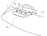
(Eighth embodiment)
Next, an eighth embodiment of the present invention will be described focusing on the differences from the above embodiment. In the above embodiment, an example in which a linear image is displayed has been described. However, in the present embodiment, as shown in FIG. 16, a real image 47 and a virtual image 37 in which a plurality of arc images 46 and 38 are arranged at intervals in the depth direction. Is displayed.
具体的には、インパネ上面部101のコンバイナ2の手前側には運転者200に目視可能に実像表示部4Cが設けられている。この実像表示部4Cは、奥行方向に間隔をあけて連なった複数の円弧像46を実像47として表示する。各円弧像46は、それら円弧像46を左右方向に2等分する点が左右中心面130上に位置し、左右中心面130に対して左右対称となっている。各円弧像46は、円弧の内側が運転者200側に向くように表示される。各円弧像46は、運転者200から見て奥側の円弧像46ほど円弧長が長くなっている。
Specifically, a real image display unit 4 </ b> C is provided on the instrument panel upper surface portion 101 in front of the combiner 2 so that the driver 200 can see the real image display unit 4 </ b> C. The real image display unit 4 </ b> C displays a plurality of arc images 46 that are arranged at intervals in the depth direction as real images 47. Each arc image 46 is symmetric with respect to the left and right central plane 130 at a point that bisects the arc image 46 in the left and right direction on the left and right central plane 130. Each arc image 46 is displayed such that the inside of the arc faces the driver 200 side. Each arc image 46 has a longer arc length as the arc image 46 on the back side as viewed from the driver 200.
実像表示部4Cは、例えば第1実施形態に準じて、複数の光源と、光源を実装する基板と、光源及び基板を収容する収容部と、光源の上方を覆うように設けられて光源からの光を拡散して出射する拡散板とを、含んで構成される。拡散板の形状は、複数の円弧像46に対応するように、複数の円弧が奥行方向に間隔をあけて連なった形状となっている。
For example, according to the first embodiment, the real image display unit 4C is provided so as to cover a plurality of light sources, a substrate on which the light sources are mounted, a light source and a housing unit that accommodates the substrate, and the light source. And a diffusing plate that diffuses and emits light. The shape of the diffuser plate is a shape in which a plurality of arcs are connected at intervals in the depth direction so as to correspond to the plurality of arc images 46.
フード120内には、複数の円弧像38が奥行方向に間隔をあけて連なった虚像37をコンバイナ2の前方にて結像させる虚像光源ユニット3Cが、設けられている。ここで、虚像37を構成する各円弧像38は、実像表示部4Cの円弧像46と同様に、円弧像38を左右方向に2等分する点が左右中心面130上に位置し、左右中心面130に対して左右対称となっている。各円弧像38は、円弧の内側が運転者200側に向くように表示される。各円弧像38は、運転者200から見て奥側の円弧像38ほど円弧長が長くなっている。各円弧像38の円弧長は、実像表示部4Cの円弧像46の円弧長よりも長い。
In the hood 120, a virtual image light source unit 3C that forms a virtual image 37 in which a plurality of arc images 38 are arranged at intervals in the depth direction in front of the combiner 2 is provided. Here, each arc image 38 constituting the virtual image 37 is located on the left and right center plane 130 at the point that bisects the arc image 38 in the left-right direction, like the arc image 46 of the real image display unit 4C. It is symmetrical with respect to the plane 130. Each arc image 38 is displayed so that the inside of the arc faces the driver 200 side. Each arc image 38 has a longer arc length as the arc image 38 on the back side as viewed from the driver 200. The arc length of each arc image 38 is longer than the arc length of the arc image 46 of the real image display portion 4C.
虚像光源ユニット3Cは、複数の円弧像38が間隔をあけて連なった表示像39Cの光を出射するように、構成されている。虚像光源ユニット3Cは、例えば第1実施形態に準じて、複数の光源と、光源を実装する基板と、光源及び基板を収容する収容部と、光源の上方を覆うように設けられて光源からの光を拡散して出射する拡散板とを、含んで構成される。拡散板の形状は、複数の円弧像38に対応するように、複数の円弧が間隔をあけて連なった形状となっている。
The virtual image light source unit 3C is configured so as to emit light of a display image 39C in which a plurality of arc images 38 are arranged at intervals. For example, according to the first embodiment, the virtual image light source unit 3C is provided so as to cover a plurality of light sources, a substrate on which the light sources are mounted, a light source and a housing portion that accommodates the substrate, and an upper portion of the light source. And a diffusing plate that diffuses and emits light. The shape of the diffusing plate is a shape in which a plurality of arcs are connected at intervals to correspond to the plurality of arc images 38.
虚像光源ユニット3Cは、複数の円弧像38から構成された表示像39Cをインパネ上面部101の奥行方向に寝かせた虚像37が結像されるように、傾けて配置されている。
The virtual image light source unit 3 </ b> C is disposed so as to be inclined so that a virtual image 37 in which a display image 39 </ b> C composed of a plurality of arc images 38 is laid in the depth direction of the instrument panel upper surface 101 is formed.
車両には、前方車両との車間距離を計測するための波(ミリ波等)を車両前方に送信するレーダ(図示外)が搭載されている。制御部5(図8参照)はこのレーダの作動時に、実像表示部4及び虚像光源ユニット3を点灯させる。
The vehicle is equipped with a radar (not shown) that transmits a wave (millimeter wave or the like) for measuring the inter-vehicle distance from the preceding vehicle to the front of the vehicle. The control unit 5 (see FIG. 8) turns on the real image display unit 4 and the virtual image light source unit 3 when the radar is operated.
本実施形態によれば、レーダ作動時に、奥行方向に向かうにしたがって次第に円弧長が大きくなる複数の円弧像46、38が連なって表示されるので、運転者200にレーダが作動していることを把握させやすくできる。
According to the present embodiment, when the radar is activated, a plurality of arc images 46 and 38 that gradually increase in arc length as they go in the depth direction are displayed in succession, so that the driver 200 is operating the radar. Easy to grasp.
(第9実施形態)
次に本発明の第9実施形態を、上記実施形態と異なる部分を中心に説明する。図17、図18に示すように、インパネ上面部101には有底の凹部104が形成されている。凹部104は、運転席の正面位置に形成されており、具体的には、凹部104の左右方向における中心に左右中心面130が位置している。左右中心面130よりも凹部104の右側及び左側が、左右中心面130に対して対称な形状となっている。また凹部104は、インパネ上面部101の奥行方向の奥側に向かうにしたがって次第に左右幅が狭くなっていく形状に、形成されている。
(Ninth embodiment)
Next, 9th Embodiment of this invention is described centering on a different part from the said embodiment. As shown in FIGS. 17 and 18, a bottomed recess 104 is formed in the instrument panel upper surface portion 101. The recess 104 is formed at the front position of the driver's seat. Specifically, the left and right center plane 130 is located at the center of the recess 104 in the left-right direction. The right and left sides of the recess 104 are symmetric with respect to the left and right center plane 130 with respect to the left and right center plane 130. Moreover, the recessed part 104 is formed in the shape where the left-right width | variety becomes narrow gradually as it goes to the depth side of the depth direction of the instrument panel upper surface part 101. As shown in FIG.
凹部104は、図19に示すように、底面部104aと側面部104bとを有している。底面部104aでは、奥行方向における一端がインストルメントパネル100の前面部102の上端に接続され、他端が後述するメータ8の下端に接続されている。
As shown in FIG. 19, the concave portion 104 has a bottom surface portion 104a and a side surface portion 104b. In the bottom surface portion 104a, one end in the depth direction is connected to the upper end of the front surface portion 102 of the instrument panel 100, and the other end is connected to the lower end of the meter 8 described later.
側面部104bは、底面部104aの左右端のそれぞれに設けられており、底面部104aから上方に起立するように設けられている。側面部104bでは、奥行方向における一端がインストルメントパネル100の前面部102に接続され、他端がメータ8の左右端に接続されている。側面部104bの下端は、底面部104aに接続されている。側面部104bには、空間部108が形成されている。詳しくは側面部104bの上端は、インパネ上面部101の位置までは達しておらず、インパネ上面部101より下側位置においてインパネ上面部101と間隔をあけて配置されている。また、インパネ上面部101において左右端側上面部101eの下側には、左右端側上面部101eと間隔をあけて側面部104bから張り出すように張出部106が設けられている。底面部104a、側面部104b及び張出部106は、同一板材で形成されている。
The side surface portion 104b is provided at each of the left and right ends of the bottom surface portion 104a, and is provided so as to rise upward from the bottom surface portion 104a. In the side surface portion 104 b, one end in the depth direction is connected to the front surface portion 102 of the instrument panel 100 and the other end is connected to the left and right ends of the meter 8. The lower end of the side surface portion 104b is connected to the bottom surface portion 104a. A space portion 108 is formed in the side surface portion 104b. Specifically, the upper end of the side surface portion 104 b does not reach the position of the instrument panel upper surface portion 101, and is disposed at a position lower than the instrument panel upper surface portion 101 and spaced from the instrument panel upper surface portion 101. Further, an extension portion 106 is provided below the left and right end upper surface portions 101e of the instrument panel upper surface portion 101 so as to protrude from the side surface portion 104b with a space from the left and right end upper surface portions 101e. The bottom surface portion 104a, the side surface portion 104b, and the overhang portion 106 are formed of the same plate material.
左右端側上面部101eの裏面側には、裏面板部112が設けられている。裏面板部112は、左右端側上面部101eの裏面に接触するように設けられている。また、側面部104bから凹んだ位置において張出部106と裏面板部112の間を架け渡すように、底板部107が設けられている。
A back plate portion 112 is provided on the back side of the left and right end side top surface portion 101e. The back plate portion 112 is provided so as to contact the back surface of the left and right end side upper surface portion 101e. In addition, a bottom plate portion 107 is provided so as to bridge between the overhang portion 106 and the back plate portion 112 at a position recessed from the side surface portion 104b.
これら左右端側上面部101e、張出部106、裏面板部112及び底板部107により空間部108が形成されている。すなわち左右端側上面部101e、張出部106、裏面板部112及び底板部107は、空間部108の壁部を構成している。空間部108の壁部となる各部101e、106、112、107は、遮光性の材料で形成されている。また空間部108は、左右中心面130側に開口109を有し、当該開口109以外は遮光性の各部101e、106、112、107に囲まれた空間となっている。ここで開口109は、運転者200から視認可能である。さらに、図19の紙面に直交する方向(すなわちインパネ上面部101の奥行方向)における空間部108の幅は、凹部104の奥行方向における幅と同等である。
A space portion 108 is formed by the left and right end side upper surface portions 101 e, the overhang portions 106, the back plate portion 112, and the bottom plate portion 107. That is, the left and right end upper surface portions 101 e, the overhang portions 106, the back plate portion 112, and the bottom plate portion 107 constitute a wall portion of the space portion 108. Each part 101e, 106, 112, 107 which becomes the wall part of the space part 108 is formed of a light-shielding material. The space portion 108 has an opening 109 on the left and right center plane 130 side, and the space other than the opening 109 is a space surrounded by the light shielding portions 101e, 106, 112, and 107. Here, the opening 109 is visible to the driver 200. Further, the width of the space 108 in the direction orthogonal to the paper surface of FIG. 19 (that is, the depth direction of the instrument panel upper surface portion 101) is equal to the width of the recess 104 in the depth direction.
凹部104において右側及び左側の側面部104bに形成された空間部108には、図17、18に示すように、それぞれ実像表示部4A、4Bが設けられている。運転者200から見て右側に配置された実像表示部4Aは、図19のように設けられている。詳しくは実像表示部4Aは、複数の光源41と、光源41を実装する基板42と、光源41の光出射方向を覆うように設けられて光源41からの光を拡散して出射する拡散板44とを、有する。光源41は、例えばLEDである。基板42は、細長長方形状に形成されている。基板42は、長手方向がインパネ上面部101の奥行方向(すなわち図19の紙面に直交する方向)に向き、かつ光源41の実装面が空間部108の開口109に向くように、配置される。なお、基板42は、例えば底板部107にネジ等により固定されている。
As shown in FIGS. 17 and 18, real image display portions 4 </ b> A and 4 </ b> B are provided in the space portions 108 formed in the right and left side portions 104 b in the concave portion 104, respectively. The real image display unit 4A arranged on the right side when viewed from the driver 200 is provided as shown in FIG. Specifically, the real image display unit 4A includes a plurality of light sources 41, a substrate 42 on which the light sources 41 are mounted, and a diffusion plate 44 that is provided so as to cover the light emission direction of the light sources 41 and diffuses and emits light from the light sources 41. And having. The light source 41 is, for example, an LED. The substrate 42 is formed in an elongated rectangular shape. The substrate 42 is arranged such that the longitudinal direction is in the depth direction of the instrument panel upper surface portion 101 (that is, the direction orthogonal to the paper surface of FIG. 19), and the mounting surface of the light source 41 is directed to the opening 109 of the space portion 108. The substrate 42 is fixed to the bottom plate portion 107 with screws or the like, for example.
複数の光源41は、基板42の長手方向に沿って一直線上に実装されている。光源41は、空間部108の開口109に向けて光を出射するように、設けられる。
The plurality of light sources 41 are mounted on a straight line along the longitudinal direction of the substrate 42. The light source 41 is provided so as to emit light toward the opening 109 of the space 108.
拡散板44は、空間部108の開口109と同等の形状、すなわち細長長方形状に形成されている。拡散板44は、開口109を塞ぐように設けられている。図19では拡散板44は、側面部104bから若干引っ込んだ位置に設けられているが、側面部104bと同一平面を形成するように設けられていても良い。張出部106には、拡散板44を設置するための凹部150が形成されている。拡散板44の下端は、この凹部150に嵌まっている。また拡散板44の上端は、裏面板部112又は左右端側上面部101eに固定されている。
The diffuser plate 44 is formed in a shape equivalent to the opening 109 of the space portion 108, that is, an elongated rectangular shape. The diffusion plate 44 is provided so as to close the opening 109. In FIG. 19, the diffusion plate 44 is provided at a position slightly retracted from the side surface portion 104b. However, the diffusion plate 44 may be provided so as to form the same plane as the side surface portion 104b. A concave portion 150 for installing the diffusion plate 44 is formed in the overhanging portion 106. The lower end of the diffusion plate 44 is fitted in the recess 150. Further, the upper end of the diffusion plate 44 is fixed to the back plate portion 112 or the left and right end side upper surface portion 101e.
光源41からの光が拡散板44を介して開口109から出射されることで、当該開口109が照明される。この照明像は、インパネ上面部101の奥行方向に長さを有した直線状の像となる。
The light from the light source 41 is emitted from the opening 109 via the diffusion plate 44, so that the opening 109 is illuminated. This illumination image is a linear image having a length in the depth direction of the instrument panel upper surface portion 101.
なお、図17に示す他方の実像表示部4Bの構成は、実像表示部4Aの構成と同様である。
The configuration of the other real image display unit 4B shown in FIG. 17 is the same as the configuration of the real image display unit 4A.
実像表示部4A、4Bは、左右中心面130に対して斜めの角度に、第7実施形態に準じて設けられている。具体的には実像表示部4A、4Bは、奥行方向の奥側に向かうにしたがって次第に左右中心面130に近づいていくように、設けられる。したがって、実像表示部4A、4Bが表示する実像45A、45Bも、奥行方向に向かうにしたがって次第に左右中心面130に近づいていく。
The real image display units 4A and 4B are provided according to the seventh embodiment at an oblique angle with respect to the left and right central plane 130. Specifically, the real image display units 4A and 4B are provided so as to gradually approach the left and right center plane 130 as they go to the depth side in the depth direction. Therefore, the real images 45A and 45B displayed by the real image display units 4A and 4B gradually approach the left and right center plane 130 as they go in the depth direction.
虚像光源ユニット3A、3B(図18参照)は、各実像表示部4A、4Bによる実像45A、45Bの延長線131A、131B上にそれぞれ虚像35A、35Bを結像させるように、設けられている。図18に示すように虚像光源ユニット3A、3Bは、凹部104に配置されており、それ以外は第7実施形態と同様である。なお、凹部104もインパネ上面部101の一部と考えると、本実施形態においても、虚像光源ユニット3はインパネ上面部101に配置されているといえる。
The virtual image light source units 3A and 3B (see FIG. 18) are provided so that the virtual images 35A and 35B are formed on the extension lines 131A and 131B of the real images 45A and 45B by the real image display units 4A and 4B, respectively. As shown in FIG. 18, the virtual image light source units 3A and 3B are disposed in the recess 104, and the rest is the same as in the seventh embodiment. If the concave portion 104 is also considered as a part of the instrument panel upper surface portion 101, it can be said that the virtual image light source unit 3 is also disposed on the instrument panel upper surface portion 101 in this embodiment.
図17に示すように、凹部104の奥行方向における奥側の端部には、例えば車速、エンジン回転数等を表示するメータ8が配置されている。図20に示すようにメータ8は、カバー81と、文字板82と、指針83と、基板84と、LED85と、モータ86と、ケース87と、支持部88とを備えている。
As shown in FIG. 17, a meter 8 that displays, for example, a vehicle speed, an engine speed, and the like is disposed at the end of the recess 104 in the depth direction. As shown in FIG. 20, the meter 8 includes a cover 81, a dial plate 82, a pointer 83, a substrate 84, an LED 85, a motor 86, a case 87, and a support portion 88.
カバー81は、メータ8の最前面に配置される部材であり、例えばポリカーボネート等の透明樹脂により略長方形の板状に形成されている。カバー81は、凹部104の運転席側に向いた正面を構成し、凹部104の底面部104aから上方に起立するように設けられている。詳しくは、インパネ上面部101のうち凹部104の奥側に位置する部分を奥側インパネ上面部101c(図18参照)としたときにカバー81は、底面部104aの奥側の端部と奥側インパネ上面部101cの手前側の端部との間を架け渡す形態にて、設けられている。カバー81の下端は、ケース87に固定されている。カバー81の上端は、奥側インパネ上面部101cの手前側の端部に固定されている。詳しくは、奥側インパネ上面部101cの手前側の端部の裏面側には裏面部材113が設けられており、カバー81の上端はこの裏面部材113に固定されている。
The cover 81 is a member disposed on the forefront of the meter 8 and is formed in a substantially rectangular plate shape with a transparent resin such as polycarbonate. The cover 81 constitutes a front surface facing the driver's seat side of the recess 104 and is provided to stand upward from the bottom surface portion 104 a of the recess 104. Specifically, when the portion located on the inner side of the recess 104 in the instrument panel upper surface portion 101 is the inner instrument panel upper surface portion 101c (see FIG. 18), the cover 81 is connected to the rear end and the inner side of the bottom surface portion 104a. It is provided in a form that spans between the front end portion of the instrument panel upper surface portion 101c. The lower end of the cover 81 is fixed to the case 87. The upper end of the cover 81 is fixed to the front end of the back instrument panel upper surface 101c. Specifically, a back member 113 is provided on the back side of the front end of the back instrument panel top surface 101 c, and the upper end of the cover 81 is fixed to the back member 113.
文字板82は、カバー81の背後に配置されている。文字板82は、例えばポリカーボネート等の透明樹脂により形成された基材と、当該基材の表面又は裏面に形成された遮光印刷層とを、有する。文字板82には、部分的に遮光印刷層が形成されていない部分が存在する。この遮光印刷層が形成されていない部分は、文字板82の照明部を構成する。文字板82の照明部は光を透過し、それ以外の部分(遮光印刷層が形成された部分)は遮光する。照明部には、指針83の指示する目盛部が含まれている。文字板82の表面は、メータ8の表示面を構成し、目盛部等の照明部による像が表示される。
The dial plate 82 is disposed behind the cover 81. The dial plate 82 has a base material formed of a transparent resin such as polycarbonate, and a light-shielding print layer formed on the front surface or the back surface of the base material. The dial 82 includes a portion where the light-shielding print layer is not partially formed. The portion where the light-shielding print layer is not formed constitutes the illumination portion of the dial plate 82. The illuminating portion of the dial 82 transmits light, and the other portions (portions where the light-shielding print layer is formed) are shielded from light. The illumination part includes a scale part indicated by the pointer 83. The surface of the dial plate 82 constitutes the display surface of the meter 8, and an image by an illumination unit such as a scale unit is displayed.
文字板82は、奥行方向に傾いた状態で配置されている。すなわち、文字板82の下端82aよりも上端82bの方が奥側に位置している。また上端82bは、下端82aよりも高い位置に位置している。
The dial 82 is arranged in a state of being inclined in the depth direction. That is, the upper end 82b is located on the back side of the lower end 82a of the dial plate 82. The upper end 82b is positioned higher than the lower end 82a.
指針83は、文字板82の表面に沿って回転可能に設けられる。詳しくは指針83は、基部83aから裏側に突出する突出部83cを、有する。文字板82には、突出部83cが設けられる位置に穴82cが形成されており、突出部83cはこの穴82cに挿入された状態で設けられる。突出部83cは、文字板82に直角に設けられる回転軸831の一端に、接続されている。突出部83c及び基部83aは、文字板82の上端82bよりも下端82aに寄った位置に配置されている。基部83aが回転軸831の中心線回りに回転することで、指針83の先端83bが半円状の軌跡で移動する(図17も参照)。この指針83の移動軌跡に沿って目盛部が形成されている。なお、目盛部は、指針83の移動軌跡と同様に半円状に形成されている。また指針83は、例えばアクリル等の導光体で形成されており、照明可能に構成されている。
The pointer 83 is provided to be rotatable along the surface of the dial plate 82. Specifically, the pointer 83 has a protrusion 83c that protrudes from the base 83a to the back side. A hole 82c is formed in the dial plate 82 at a position where the protruding portion 83c is provided, and the protruding portion 83c is provided in a state of being inserted into the hole 82c. The protruding portion 83 c is connected to one end of a rotating shaft 831 provided at a right angle to the dial plate 82. The protruding portion 83c and the base portion 83a are disposed at a position closer to the lower end 82a than the upper end 82b of the dial plate 82. When the base 83a rotates around the center line of the rotation shaft 831, the tip 83b of the pointer 83 moves along a semicircular locus (see also FIG. 17). A scale portion is formed along the movement locus of the pointer 83. The scale portion is formed in a semicircular shape like the movement locus of the pointer 83. The pointer 83 is formed of a light guide such as acrylic, and is configured to be illuminable.
基板84は、文字板82の背後において文字板82と平行に配置されている。基板84の文字板82側の面には、文字板82の照明部(目盛部等)及び指針83の基部83aに向けて光を出射するように、LED85が実装されている。基板84の裏面側には、指針83を駆動するためのモータ86が配置されている。モータ86は、回転軸831において指針83が接続される側とは反対側の端部に接続されて、回転軸831を回転させる。
The substrate 84 is disposed behind the dial plate 82 in parallel with the dial plate 82. An LED 85 is mounted on the surface of the board 84 on the dial plate 82 side so as to emit light toward the illuminating portion (scale unit or the like) of the dial plate 82 and the base 83 a of the pointer 83. A motor 86 for driving the pointer 83 is disposed on the back side of the substrate 84. The motor 86 is connected to the end of the rotating shaft 831 opposite to the side to which the hands 83 are connected, and rotates the rotating shaft 831.
ケース87は、奥側インパネ上面部101cの下側に配置されて、メータ8を構成する各部を収容又は支持する。ケース87は、例えばPP(ポリプロピレン)樹脂、ABS樹脂等の遮光性を有する樹脂により、形成されている。
The case 87 is disposed on the lower side of the back instrument panel upper surface portion 101 c and accommodates or supports each portion constituting the meter 8. The case 87 is made of a light-shielding resin such as PP (polypropylene) resin or ABS resin.
支持部88は、文字板82及び基板84を支持する部分である。支持部88は、例えばPP(ポリプロピレン)樹脂、ABS樹脂等の遮光性を有する樹脂により、形成されている。
The support portion 88 is a portion that supports the dial plate 82 and the substrate 84. The support portion 88 is made of a light-shielding resin such as PP (polypropylene) resin or ABS resin.
メータ8は、LED85及びモータ86を制御する制御部を、有する。この制御部は、実像表示部4A、4B及び虚像光源ユニット3A、3Bを制御する制御部5(図8参照)と同一であっても良いし、制御部5とは別に設けられていても良い。また制御部は、基板84に実装されていても良いし、基板84以外の部分に設けられていても良い。
The meter 8 has a control unit that controls the LED 85 and the motor 86. This control unit may be the same as the control unit 5 (see FIG. 8) that controls the real image display units 4A and 4B and the virtual image light source units 3A and 3B, or may be provided separately from the control unit 5. . The control unit may be mounted on the substrate 84 or may be provided in a portion other than the substrate 84.
メータ8の制御部は、メータ8を作動させる時には、LED85を点灯させて文字板82の照明部及び指針83を照明する。加えて制御部は、例えば車速、エンジン回転数等を検出するセンサの検出値を取得して、指針83が当該検出値を指示するようにモータ86を回転させる。
When operating the meter 8, the control unit of the meter 8 turns on the LED 85 to illuminate the illumination unit of the dial 82 and the pointer 83. In addition, the control unit acquires a detection value of a sensor that detects, for example, the vehicle speed, the engine speed, and the like, and rotates the motor 86 so that the pointer 83 indicates the detection value.
コンバイナ2は、奥側インパネ上面部101cの手前側の端部から上方に起立するように、設けられている。すなわちコンバイナ2は、メータ8のカバー81と同等の奥行方向位置に設けられている。これによりコンバイナ2の下側には、カバー81が配置されている。
The combiner 2 is provided so as to stand upward from an end on the near side of the back-side instrument panel upper surface 101c. That is, the combiner 2 is provided at a position in the depth direction equivalent to the cover 81 of the meter 8. As a result, the cover 81 is disposed below the combiner 2.
コンバイナ2は、下部に取付部22を有し、当該取付部22が奥側インパネ上面部101cに取り付けられている。詳しくは取付部22は、コンバイナ2の裏側の方向に、コンバイナ2の入射面21に対して略直角に突出するように、形成されている。取付部22は、奥側インパネ上面部101cと、裏面部材113の間に挟み込まれるようにして取り付けられている。このようにコンバイナ2は、奥側インパネ上面部101cに対して常時起立した状態に、取り付けられる。
The combiner 2 has an attachment portion 22 at the lower portion, and the attachment portion 22 is attached to the back instrument panel upper surface portion 101c. Specifically, the attachment portion 22 is formed so as to protrude substantially perpendicular to the incident surface 21 of the combiner 2 in the direction of the back side of the combiner 2. The attachment portion 22 is attached so as to be sandwiched between the back instrument panel upper surface portion 101 c and the back surface member 113. Thus, the combiner 2 is attached in the state which always stood up with respect to the back | inner instrument panel upper surface part 101c.
以下、本実施形態の効果を説明する。本実施形態によれば、上記実施形態の効果に加えて、右側実像45Aと右側虚像35Aとで構成される右側直線像と、左側実像45Bと左側虚像35Bとで構成される左側直線像とは、全体として末広がり(ハの字状)の像を構成することになるので、車両前方に伸びた道路を想起させやすくできる。これにより、自動で車線維持が行われていることを、運転者200により一層把握させやすくできる。
Hereinafter, the effect of this embodiment will be described. According to the present embodiment, in addition to the effects of the above-described embodiment, the right straight image formed by the right real image 45A and the right virtual image 35A and the left straight image formed by the left real image 45B and the left virtual image 35B are as follows: Since, as a whole, an end-spread (C-shaped) image is formed, a road extending in front of the vehicle can be easily recalled. This makes it easier for the driver 200 to grasp that the lane is maintained automatically.
また、実像表示部4A、4Bは凹部104の側面部104bに設けられ、すなわち車両の左右方向の向きに実像45A、45Bの光を出射するように設けられ、さらに光源41の上方が遮光性の左右端側上面部101eで覆われているので、実像表示部4A、4Bからの光がフロントウィンドウ105の方向に進行してしまうのを抑制できる。これによれば、実像表示部4A、4Bの表示する実像45A、45Bがフロントウィンドウ105に映ってしまうのを抑制できる。
Further, the real image display portions 4A and 4B are provided on the side surface portion 104b of the concave portion 104, that is, provided so as to emit the light of the real images 45A and 45B in the left-right direction of the vehicle. Since it is covered with the left and right end side upper surface portions 101e, it is possible to suppress the light from the real image display portions 4A and 4B from traveling in the direction of the front window 105. According to this, it can suppress that the real images 45A and 45B which the real image display parts 4A and 4B display are reflected on the front window 105.
また、メータ8はインパネ上面部101においてインストルメントパネル100の前面部102よりも奥側に配置されているので、前面部102に配置される場合に比べて、メータ8を目視する際の運転者200の視線移動を少なくでき、メータ8の視認性を向上できる。さらにメータ8が奥側に配置されることで、インストルメントパネル100の前面部102辺りに、虚像光源ユニット3の配置スペースを確保しやすくできる。
Further, since the meter 8 is disposed on the back side of the instrument panel 100 in the instrument panel upper surface portion 101 from the front surface portion 102, the driver when viewing the meter 8 as compared with the case where the meter 8 is disposed on the front surface portion 102. The line-of-sight movement of 200 can be reduced, and the visibility of the meter 8 can be improved. Furthermore, by arranging the meter 8 on the back side, it is possible to easily secure a space for arranging the virtual image light source unit 3 around the front surface portion 102 of the instrument panel 100.
また、メータ8の文字板82は奥行方向に傾いた状態で配置されているので、傾けないで配置された場合に比べて、大きい表示面を有した文字板82を採用できる。これによれば、メータ8の表示を大きく見せることができる。
In addition, since the dial plate 82 of the meter 8 is disposed in a tilted state in the depth direction, the dial plate 82 having a larger display surface can be employed as compared with the case where the dial plate 82 is not tilted. According to this, the display of the meter 8 can be shown large.
また、コンバイナ2の下にメータ8のカバー81が配置されているので、コンバイナ2とメータ8との一体感を出すことができる。
In addition, since the cover 81 of the meter 8 is disposed under the combiner 2, a sense of unity between the combiner 2 and the meter 8 can be obtained.
(第10実施形態)
次に本発明の第10実施形態を、上記実施形態と異なる部分及び上記実施形態を補足する部分を中心に、説明する。なお、以下では、表示装置1の搭載される車両を自車両という。
(10th Embodiment)
Next, a tenth embodiment of the present invention will be described with a focus on portions different from the above embodiments and portions supplementing the above embodiments. Hereinafter, the vehicle on which the display device 1 is mounted is referred to as the host vehicle.
図21、図22に示す本実施形態では、第7実施形態に準じて左右中心面130の左右両側に表示される直線状の像35A、35B、45A、45Bは、道路のうち自車両の走行車線を区切る路面標示(例えば白線等)を表した標示図形となる。このとき、自車両において運転者200から見た右側虚像35Aよりも手前側には、延長線131A上にて当該虚像35Aと連続性を有した標示図形の右側実像45Aが、インパネ上面部101上の実像表示部4Aにより直線状に表示される、また、自車両において運転者200から見た左側虚像35Bよりも手前側には、延長線131B上にて当該虚像35Bと連続性を有した標示図形の左側実像45Bが、インパネ上面部101上の実像表示部4Bにより直線状に表示される。
In the present embodiment shown in FIGS. 21 and 22, linear images 35A, 35B, 45A, and 45B displayed on the left and right sides of the left and right center plane 130 in accordance with the seventh embodiment are the traveling of the vehicle on the road. It becomes a marking figure representing a road marking (for example, a white line) that divides the lane. At this time, on the front side of the right virtual image 35A viewed from the driver 200 in the host vehicle, a right real image 45A of a marking figure having continuity with the virtual image 35A on the extension line 131A is displayed on the instrument panel upper surface 101. Is displayed in a straight line by the real image display unit 4A, and in front of the left virtual image 35B viewed from the driver 200 in the host vehicle, an indication having continuity with the virtual image 35B on the extension line 131B The left real image 45B of the figure is displayed linearly by the real image display unit 4B on the instrument panel upper surface 101.
ここで特に図21、図22には、第9実施形態の図17に準じて断続する複数の直線状に表示された虚像35A、35Bが例示されているが、第7実施形態の図15に準じて各虚像35A、35Bがそれぞれ連続する単一の直線状(図示しない)に表示されても良い。これら左右の虚像35A、35Bは、第1実施形態と同様の原理により図23に示すように、それぞれ対応する虚像光源ユニット3A、3Bの表示像39A、39Bとなる標示図形の一部が運転者200から見て奥行方向に寝かせられることで、同方向にて長さを有する形状に結像される。
Here, in particular, FIGS. 21 and 22 illustrate a plurality of linearly displayed virtual images 35A and 35B according to FIG. 17 of the ninth embodiment, but in FIG. 15 of the seventh embodiment. Accordingly, the virtual images 35A and 35B may be displayed in a single continuous straight line (not shown). As shown in FIG. 23, these left and right virtual images 35A and 35B are displayed on the display image 39A and 39B of the corresponding virtual image light source units 3A and 3B, respectively. By being laid in the depth direction as viewed from 200, an image is formed in a shape having a length in the same direction.
具体的には、フード120の空間124を含むインパネ上面部101の上方空間101fのうち一部は、発光部としての各虚像光源ユニット3A、3Bからコンバイナ2まで表示像39A、39Bの光140を案内する表示光路143を、構成している。すなわち、光路形成部としてのフード120及びインパネ上面部101は、虚像光源ユニット3A、3Bからの光140をコンバイナ2へと直接的に入射させる表示光路143を、形成している。ここで表示光路143は、運転者200から見てフロントウィンドウ105よりも手前側に配置されたコンバイナ2に対して、さらに手前に形成される。
Specifically, a part of the upper space 101f of the instrument panel upper surface 101 including the space 124 of the hood 120 emits the light 140 of the display images 39A and 39B from the virtual image light source units 3A and 3B as the light emitting units to the combiner 2. A display optical path 143 to be guided is configured. That is, the hood 120 and the instrument panel upper surface portion 101 as an optical path forming portion form a display optical path 143 that allows the light 140 from the virtual image light source units 3A and 3B to enter the combiner 2 directly. Here, the display optical path 143 is formed in front of the combiner 2 disposed on the near side of the front window 105 when viewed from the driver 200.
このような表示光路143を通じた光案内作用(すなわち導光作用)により表示像39A、39Bの各虚像35A、35Bは、運転者200から見た奥行方向に寝かせて結像されることで、表示光路143の光軸144に対して傾く斜めの像面145を構成する。これにより、虚像35A、35Bの結像される像面(すなわち結像面)145は、上方へ向かうほど運転者200から離間する奥行方向(すなわち奥側)に、傾くこととなる。
The virtual images 35A and 35B of the display images 39A and 39B are imaged in the depth direction viewed from the driver 200 by the light guiding action (that is, the light guide action) through the display light path 143, thereby displaying the image. An oblique image plane 145 that is inclined with respect to the optical axis 144 of the optical path 143 is formed. Thereby, the image plane (namely, imaging plane) 145 on which the virtual images 35 </ b> A and 35 </ b> B are formed is inclined in the depth direction (that is, the back side) away from the driver 200 as it goes upward.
こうした寝かせ及び傾きは、各虚像光源ユニット3A、3Bの表示像39A、39Bを形成する出射面34aからコンバイナ2の入射面21までの光学距離が等しくなる等距離位置30に対して、当該出射面34aが第1〜第9実施形態に準じて傾けて配置されていることに、依拠する。なお、以上の寝かせ及び傾きは、第1実施形態で説明した調整機構が設けられない場合に成立することは勿論、当該調整機構が設けられる場合には虚像35A、35Bの結像位置の微調整範囲内にて成立する。
Such laying and tilting is performed with respect to the equidistant position 30 where the optical distance from the exit surface 34a forming the display images 39A and 39B of the virtual image light source units 3A and 3B to the entrance surface 21 of the combiner 2 is equal. It relies on 34a being inclined and arranged according to the first to ninth embodiments. Note that the above-described laying and tilting are not only established when the adjustment mechanism described in the first embodiment is not provided, but also when the adjustment mechanism is provided, fine adjustment of the imaging positions of the virtual images 35A and 35B. It is established within the range.
以下、本実施形態の効果を説明する。本実施形態によれば、表示像39A、39Bの正面視形状をそのまま虚像表示するのではなく、奥行き方向に寝かせた結像により表示像39A、39Bの虚像表示を、虚像光源ユニット3A、3Bからの表示光路143の光軸144に対して斜めに傾かせることとなる。すなわち、現実空間の奥行方向に長さを有した虚像表示が行われ得るので、従来の疑似的な奥行き表現に比べて、奥行き感を出すことが可能となる。
Hereinafter, the effect of this embodiment will be described. According to the present embodiment, the front-view shape of the display images 39A and 39B is not displayed as it is, but the virtual images of the display images 39A and 39B are displayed from the virtual image light source units 3A and 3B by image formation laid down in the depth direction. The optical axis 144 of the display optical path 143 is tilted obliquely. That is, since a virtual image display having a length in the depth direction of the real space can be performed, a sense of depth can be obtained as compared with the conventional pseudo depth expression.
また、運転者200から見て自車両のフロントウィンドウ105よりも手前側のコンバイナ2により表示像39A、39Bが反射されることで、奥行き方向に寝かせた虚像35A、35Bが結像され得る。これによれば、体格の制限されるコンバイナ2を虚像結像部材とした場合でも、奥行き感を出す虚像表示を実現することが可能となる。しかも、コンバイナ2までの光学距離が等しくなる等距離位置30に対して傾けた虚像光源ユニット3A、3Bによれば、虚像表示を奥行き方向に確実に寝かせて奥行き感を出すことが可能となる。
Further, the display images 39A and 39B are reflected by the combiner 2 on the nearer side than the front window 105 of the host vehicle as viewed from the driver 200, so that virtual images 35A and 35B laid down in the depth direction can be formed. According to this, even when the combiner 2 whose physique is limited is a virtual image forming member, it is possible to realize a virtual image display that gives a sense of depth. Moreover, according to the virtual image light source units 3A and 3B tilted with respect to the equidistant position 30 where the optical distances to the combiner 2 are equal, it is possible to surely lay the virtual image display in the depth direction and give a sense of depth.
また、路面標示を表した標示図形である表示像39A、39Bの虚像35A、35Bよりも手前側に、それぞれ虚像35A、35Bとの連続性を有した標示図形の実像45A、45Bが表示されることによれば、それら虚像35A、35Bの奥行感が強調され得る。なお、以上の本実施形態の効果は、先に説明した第1〜第9実施形態でも同様に発揮され得る。
In addition, the real images 45A and 45B of the marking graphic having continuity with the virtual images 35A and 35B are displayed on the near side of the virtual images 35A and 35B of the display images 39A and 39B, which are the marking graphics representing road markings, respectively. According to this, the sense of depth of these virtual images 35A and 35B can be emphasized. In addition, the effect of the above this embodiment can be exhibited similarly also in the 1st-9th embodiment demonstrated previously.
(第11実施形態)
次に本発明の第11実施形態を、上記実施形態と異なる部分を中心に説明する。図24、図25に示す本実施形態では、第10実施形態の表示構成に加えて、虚像71を表示する第5実施形態の液晶ディスプレイ7が追加されている。
(Eleventh embodiment)
Next, an eleventh embodiment of the present invention will be described centering on differences from the above embodiment. In this embodiment shown in FIGS. 24 and 25, in addition to the display configuration of the tenth embodiment, the liquid crystal display 7 of the fifth embodiment that displays a virtual image 71 is added.
図25に示す第2発光部としての液晶ディスプレイ7は、フード120内のうち、左右の虚像35A、35Bを表示する第1発光部としての虚像光源ユニット3A、3B間に、配置されている。液晶ディスプレイ7は、虚像光源ユニット3A、3Bの表示像39A、39Bである標示図形とは異なる表示像70の光146として、液晶画面72に表示した画像の光を、図26に示す如くコンバイナ2へと向けて出射する。液晶ディスプレイ7からの出射光146がコンバイナ2にて運転者200側に反射されることで、コンバイナ2の前方に表示像70の虚像71が結像される。
The liquid crystal display 7 as the second light emitting unit shown in FIG. 25 is disposed between the virtual image light source units 3A and 3B as the first light emitting units that display the left and right virtual images 35A and 35B in the hood 120. As shown in FIG. 26, the liquid crystal display 7 converts the light of the image displayed on the liquid crystal screen 72 as the light 146 of the display image 70 that is different from the display figures 39A and 39B of the virtual image light source units 3A and 3B. Exit toward The emitted light 146 from the liquid crystal display 7 is reflected by the combiner 2 toward the driver 200, so that a virtual image 71 of the display image 70 is formed in front of the combiner 2.
その結果、図24に示すように本実施形態では、自車両を例えば模式絵又は写真等で表した車両図形が、表示像70の虚像71として表示される。このとき虚像71は、図24、25に示すように実像表示部4A、4Bの左右中心面130上となる限りにて、虚像35A、35B間のうち走行車線における自車両の左右位置に応じた箇所に、表示される。それと共に虚像71は、第5実施形態と同様の原理により図26に示すように、液晶ディスプレイ7の表示像70となる車両図形を運転者200から見て奥行方向には実質寝かせないで、同方向にて実質長さを有しない形状に結像される。
As a result, as shown in FIG. 24, in the present embodiment, a vehicle figure representing the host vehicle with a schematic picture or a photograph is displayed as a virtual image 71 of the display image 70. At this time, as long as the virtual image 71 is on the left and right center plane 130 of the real image display units 4A and 4B as shown in FIGS. 24 and 25, the virtual image 71 corresponds to the left and right positions of the host vehicle in the traveling lane among the virtual images 35A and 35B. It is displayed at the location. At the same time, as shown in FIG. 26, the virtual image 71 is substantially the same as the virtual image 71 in the depth direction when viewed from the driver 200, as shown in FIG. The image is formed into a shape having no substantial length in the direction.
具体的には、フード120の空間124を含むインパネ上面部101の上方空間101fの一部は、表示像70の光146を液晶ディスプレイ7からコンバイナ2まで案内する表示光路147を、構成している。すなわち、光路形成部としてのフード120及びインパネ上面部101は、第10実施形態で説明の表示光路143と同様な第1表示光路143に加えて、液晶ディスプレイ7からの光146をコンバイナ2へと直接的に入射させる第2表示光路147を、形成している。ここで、運転者200の前方視野内においてコンバイナ2は、各虚像光源ユニット3A、3Bからの第1表示光路143上だけでなく、液晶ディスプレイ7からの第2表示光路147上にも、配置されている。
Specifically, a part of the upper space 101 f of the instrument panel upper surface portion 101 including the space 124 of the hood 120 constitutes a display optical path 147 for guiding the light 146 of the display image 70 from the liquid crystal display 7 to the combiner 2. . In other words, the hood 120 and the instrument panel upper surface portion 101 as the optical path forming unit transmit the light 146 from the liquid crystal display 7 to the combiner 2 in addition to the first display optical path 143 similar to the display optical path 143 described in the tenth embodiment. A second display optical path 147 for direct incidence is formed. Here, the combiner 2 is disposed not only on the first display light path 143 from each of the virtual image light source units 3A and 3B but also on the second display light path 147 from the liquid crystal display 7 in the front view of the driver 200. ing.
このような第2表示光路147を通じた光案内作用(すなわち導光作用)により表示像70の虚像71は、運転者200から見た奥行方向での寝かせ具合が実質0となるように結像されることで、第2表示光路147の光軸148に対して実質垂直な像面149を構成する。これにより、第2表示像となる表示像70の虚像71が結像される像面(すなわち結像面)149の奥行方向への寝かせ具合は、第1表示像となる表示像39A、39Bの虚像35A、35Bが第10実施形態と同様に結像される像面145の奥行方向への寝かせ具合(図23参照)よりも、小さくなる。
The virtual image 71 of the display image 70 is formed by the light guiding action (that is, the light guiding action) through the second display light path 147 as described above so that the laying state in the depth direction viewed from the driver 200 is substantially zero. Thus, an image plane 149 substantially perpendicular to the optical axis 148 of the second display optical path 147 is configured. As a result, the laying state in the depth direction of the image plane (that is, the imaging plane) 149 on which the virtual image 71 of the display image 70 to be the second display image is formed is the same as that of the display images 39A and 39B to be the first display images. The virtual images 35 </ b> A and 35 </ b> B are smaller than the degree of laying in the depth direction of the image plane 145 formed in the same manner as in the tenth embodiment (see FIG. 23).
こうした寝かせ具合は、液晶ディスプレイ7の表示像70を形成する液晶画面72からコンバイナ2の入射面21までの光学距離が等しくなる等距離位置にて、当該画面72が第5実施形態に準じて入射面21と実質平行に配置されていることに、依拠する。なお、以上の寝かせ具合は、第1実施形態で説明した調整機構が設けられない場合に成立することは勿論、当該調整機構が設けられる場合には虚像35A、35B、71の結像位置の微調整範囲内にて成立する。
Such a laying condition is such that the screen 72 is incident according to the fifth embodiment at an equal distance position where the optical distance from the liquid crystal screen 72 forming the display image 70 of the liquid crystal display 7 to the incident surface 21 of the combiner 2 becomes equal. Rely on being arranged substantially parallel to the surface 21. Note that the above-described laying condition is established when the adjustment mechanism described in the first embodiment is not provided, and of course, when the adjustment mechanism is provided, the imaging positions of the virtual images 35A, 35B, and 71 are fine. It is established within the adjustment range.
以下、本実施形態の効果を説明する。本実施形態によれば、表示像70の虚像71が結像される像面149の奥行方向への寝かせ具合は、表示像39A、39Bの虚像35A、35Bが結像される像面145の奥行方向への寝かせ具合よりも、小さい。故に、虚像71を基準として虚像35A、35Bの奥行き感を強調できる。
Hereinafter, the effect of this embodiment will be described. According to the present embodiment, the depth of the image plane 149 in which the virtual image 71 of the display image 70 is formed in the depth direction is the depth of the image plane 145 in which the virtual images 35A and 35B of the display images 39A and 39B are formed. Smaller than laying in the direction. Therefore, the sense of depth of the virtual images 35A and 35B can be enhanced with the virtual image 71 as a reference.
ここで、自車両を表した車両図形である表示像70の虚像71に対して、路面標示を表した標示図形である表示像39A、39Bの虚像35A、35Bは、より奥行方向に寝かせて遠近表示され得る。これにより運転者200には、自車両とその前後方向に伸びる車線との位置関係を直感的に想起させて、車線維持機能の作動状態を認識させることができる。しかも、奥行方向に寝た標示図形の虚像35A、35Bよりも手前側に、それぞれ虚像35A、35Bとの連続性を有した標示図形の実像45A、45Bが、第10実施形態と同様に表示されることで、路面標示が直感的に想起され易くなり、車線維持機能の作動状態認識性が高められ得る。
Here, the virtual images 35A and 35B of the display images 39A and 39B, which are the marking figures representing the road markings, are laid down in the depth direction with respect to the virtual image 71 of the display image 70 which is the vehicle figure representing the host vehicle. Can be displayed. As a result, the driver 200 can intuitively recall the positional relationship between the host vehicle and the lane extending in the front-rear direction, and can recognize the operating state of the lane keeping function. Moreover, the real images 45A and 45B of the sign graphic having continuity with the virtual images 35A and 35B are displayed on the front side of the virtual images 35A and 35B of the sign graphic lying in the depth direction, as in the tenth embodiment. Thus, the road marking can be easily recalled intuitively, and the operation state recognizability of the lane keeping function can be enhanced.
なお、例えば前方車両等の他車両を表した車両図形である表示像70の虚像71を表示させることで、第1実施形態にて説明した当該他車両に対する加減速機能の作動状態を、運転者200に認識させるようにしても良い。
For example, by displaying a virtual image 71 of the display image 70 that is a vehicle figure representing another vehicle such as a preceding vehicle, the operating state of the acceleration / deceleration function for the other vehicle described in the first embodiment can be determined by the driver. 200 may be recognized.
(第12実施形態)
次に本発明の第12実施形態を、上記実施形態と異なる部分を中心に説明する。図27、28に示す本実施形態では、第11実施形態においてコンバイナ2が設けられない代わりに、車両のフロントウィンドウ105が虚像結像部材として機能する。
(Twelfth embodiment)
Next, a twelfth embodiment of the present invention will be described focusing on differences from the above embodiment. In the present embodiment shown in FIGS. 27 and 28, the front window 105 of the vehicle functions as a virtual image forming member instead of providing the combiner 2 in the eleventh embodiment.
具体的にフロントウィンドウ105は、虚像光源ユニット3A、3Bからの光140を運転者200の側に反射させることで、フロントウィンドウ105の前方に表示像39A、39Bの虚像35A、35Bを結像させる。またフロントウィンドウ105は、液晶ディスプレイ7からの光146を運転者200の側に反射させることで、フロントウィンドウ105の前方に表示像70の虚像71を結像させる。
Specifically, the front window 105 reflects the light 140 from the virtual image light source units 3A and 3B toward the driver 200, thereby forming the virtual images 35A and 35B of the display images 39A and 39B in front of the front window 105. . Further, the front window 105 reflects the light 146 from the liquid crystal display 7 toward the driver 200, thereby forming a virtual image 71 of the display image 70 in front of the front window 105.
そこで本実施形態のフロントウィンドウ105は、運転者200の前方視野内において各虚像光源ユニット3A、3Bからの第1表示光路143上及び液晶ディスプレイ7からの第2表示光路147上に、配置されている。それと共にフロントウィンドウ105は、車両の前方風景も視認可能に構成されている。但し、本実施形態の第1及び第2表示光路143、147は、インストルメントパネル100においてインパネ上面部101に開口する内部空間100aのうち一部ずつにより、それぞれ構成されている。
Therefore, the front window 105 of the present embodiment is disposed on the first display light path 143 from each of the virtual image light source units 3A and 3B and on the second display light path 147 from the liquid crystal display 7 in the front view of the driver 200. Yes. At the same time, the front window 105 is configured so that a front scenery of the vehicle can be visually recognized. However, the first and second display optical paths 143 and 147 of the present embodiment are respectively configured by a part of the internal space 100 a that opens to the instrument panel upper surface portion 101 in the instrument panel 100.
各虚像光源ユニット3A、3Bからの第1表示光路143上には、光140の向きを変えつつ、表示像39A、39Bを拡大してフロントウィンドウ105まで案内する拡大反射鏡90が、配置されている。また、液晶ディスプレイ7からの光146からの第2表示光路147上には、光146の向きを変えつつ、表示像70を拡大してフロントウィンドウ105まで案内する拡大反射鏡91が、配置されている。なお、以上の拡大反射鏡90、91は、光140、146の反射方向を変えるように駆動可能に配置されることで、第1実施形態で説明した調整機構を構成していても良い。
On the first display light path 143 from each of the virtual image light source units 3A and 3B, a magnifying reflector 90 is provided that enlarges the display images 39A and 39B and guides them to the front window 105 while changing the direction of the light 140. Yes. Further, on the second display optical path 147 from the light 146 from the liquid crystal display 7, an enlargement reflecting mirror 91 is arranged to enlarge the display image 70 and guide it to the front window 105 while changing the direction of the light 146. Yes. The magnifying reflectors 90 and 91 described above may be configured so as to be drivable so as to change the reflection direction of the light 140 and 146, thereby constituting the adjustment mechanism described in the first embodiment.
このような構成下、第1表示光路143を通じた光案内作用により表示像39A、39Bの各虚像35A、35Bは、第10実施形態で説明の如く奥行方向に寝かせて結像されることで、第1表示光路143の光軸144に対して傾く斜めの像面145を構成する。また、第2表示光路147を通じた光案内作用により表示像70の虚像71は、第11実施形態で説明の如く奥行方向での寝かせ具合が実質0となるように結像されることで、第2表示光路147の光軸148に対して実質垂直な像面149を構成する。
Under such a configuration, the virtual images 35A and 35B of the display images 39A and 39B are formed in the depth direction as described in the tenth embodiment by the light guiding action through the first display optical path 143. An oblique image plane 145 that is inclined with respect to the optical axis 144 of the first display optical path 143 is formed. Further, the virtual image 71 of the display image 70 is formed by the light guiding action through the second display optical path 147 so that the laying state in the depth direction becomes substantially 0 as described in the eleventh embodiment, so that the first An image plane 149 substantially perpendicular to the optical axis 148 of the two display optical path 147 is formed.
これらにより本実施形態でも、虚像71が結像される像面149の奥行方向への寝かせ具合は、虚像35A、35Bが結像される像面145の奥行方向への寝かせ具合よりも、小さくなる。なお、こうした寝かせ具合は、拡大反射鏡90、91等により構成される調整機構が設けられない場合に成立すること勿論、当該調整機構が設けられる場合には虚像35A、35B、71の結像位置の微調整範囲内にて成立する。
Accordingly, also in the present embodiment, the depth of the image plane 149 on which the virtual image 71 is formed in the depth direction is smaller than the depth of the image plane 145 on which the virtual images 35A and 35B are formed in the depth direction. . Such a laying condition is established when the adjusting mechanism constituted by the magnifying reflecting mirrors 90, 91, etc. is not provided. Of course, when the adjusting mechanism is provided, the imaging positions of the virtual images 35A, 35B, 71 are provided. It is established within the fine adjustment range.
本実施形態によれば、運転者200から見て自車両のフロントウィンドウ105により表示像39A、39B、70が反射されることで、奥行き方向に寝かせた虚像35A、35B、71が結像され得る。これによれば、虚像結像部材としてコンバイナ2を省略しても、自車両のフロントウィンドウ105を活用して、奥行き感を出す虚像表示を実現することが可能となる。
According to the present embodiment, the display images 39A, 39B, and 70 are reflected by the front window 105 of the host vehicle as viewed from the driver 200, whereby virtual images 35A, 35B, and 71 laid in the depth direction can be formed. . According to this, even if the combiner 2 is omitted as a virtual image forming member, it is possible to realize a virtual image display that gives a sense of depth by utilizing the front window 105 of the host vehicle.
(他の実施形態)
なお、本発明は上記実施形態に限定されるものはなく、特許請求の範囲の記載を逸脱しない限度で種々の変更が可能である。
(Other embodiments)
In addition, this invention is not limited to the said embodiment, A various change is possible to the limit which does not deviate from description of a claim.
例えば第1〜第11実施形態では、虚像光源ユニット3、3A、3B、3Cがインストルメントパネル100内に配置されても良い。この場合にインパネ上面部101には、虚像光源ユニット3、3A、3B、3Cからの光を出射させるための穴があけられる。また、この場合に虚像光源ユニット3、3A、3B、3Cとコンバイナ2の間には第12実施形態に準じて、虚像光源ユニット3、3A、3B、3Cからの光をコンバイナ2の方に反射させる反射鏡が設けられても良い。
For example, in the first to eleventh embodiments, the virtual image light source units 3, 3 </ b> A, 3 </ b> B, and 3 </ b> C may be disposed in the instrument panel 100. In this case, a hole for emitting light from the virtual image light source units 3, 3A, 3B, 3C is formed in the instrument panel upper surface portion 101. Further, in this case, the light from the virtual image light source units 3, 3A, 3B, 3C is reflected toward the combiner 2 between the virtual image light source units 3, 3A, 3B, 3C and the combiner 2 according to the twelfth embodiment. A reflecting mirror may be provided.
第1〜10実施形態では第12実施形態に準じて、虚像光源ユニット3、3A、3B、3Cからの光140がフロントウィンドウ105により反射されることで、虚像表示が実現されても良い。第5実施形態では第12実施形態に準じて、液晶ディスプレイ7からの光146がフロントウィンドウ105により反射されることで、虚像表示が実現されても良い。
In the first to tenth embodiments, the virtual image display may be realized by reflecting the light 140 from the virtual image light source units 3, 3 </ b> A, 3 </ b> B, and 3 </ b> C by the front window 105 according to the twelfth embodiment. In the fifth embodiment, the virtual image display may be realized by reflecting the light 146 from the liquid crystal display 7 by the front window 105 according to the twelfth embodiment.
第12実施形態では第1〜第4、第6〜第11実施形態に準じて、表示像70を虚像71として表示するための液晶ディスプレイ7が設けられなくても良い。第12実施形態では、虚像光源ユニット3A、3Bがインパネ上面部101に配置されても良い。
In the twelfth embodiment, the liquid crystal display 7 for displaying the display image 70 as the virtual image 71 may not be provided according to the first to fourth and sixth to eleventh embodiments. In the twelfth embodiment, the virtual image light source units 3 </ b> A and 3 </ b> B may be disposed on the instrument panel upper surface portion 101.
第1〜第12実施形態では、実像表示部4、4A、4B、4C及び虚像光源ユニット3、3A、3B、3Cは、出射する光の色を状況に応じて変更可能に構成されても良い。この場合に実像表示部4、4A、4B、4C及び虚像光源ユニット3、3A、3B、3Cの光源として、1つのLEDで複数色の光を発光可能な多色LEDが採用されても良いし、互いに異なる色の発光する複数の単色LEDが採用されても良い。これによって、運転者200に各状況を把握させやすくできる。例えば、通常時には白色の光を発光させ、注意喚起時には赤色の光を発光させることで、運転者200に現在の状況が注意すべき状況であることを容易に把握させることができる。
In the first to twelfth embodiments, the real image display units 4, 4A, 4B, and 4C and the virtual image light source units 3, 3A, 3B, and 3C may be configured to be able to change the color of the emitted light according to the situation. . In this case, as the light source of the real image display units 4, 4A, 4B, and 4C and the virtual image light source units 3, 3A, 3B, and 3C, a multicolor LED that can emit light of a plurality of colors with one LED may be employed. A plurality of single-color LEDs that emit different colors may be employed. This makes it easier for the driver 200 to grasp each situation. For example, white light is emitted during normal times, and red light is emitted during alerts, so that the driver 200 can easily grasp that the current situation is a situation to be noted.
第1〜第12実施形態では、実像表示部4、4A、4B、4C及び虚像光源ユニット3、3A、3B、3Cは、例えば液晶ディスプレイ又は有機ELディスプレイ等の画像表示ディスプレイにより構成されても良いし、例えば微小電気機械システム(MEMS)又はデジタルミラーデバイス(DMD)等を用いた画像投射器により構成されても良い。また第7及び第12実施形態では、液晶ディスプレイ7に代えて、他の種類のディスプレイ又は投射器が採用されても良い。これらの場合、例えばある状況では第1〜第7、第9〜12実施形態のような直線状の像を表示し、別の状況では第8実施形態のような円弧状の像を表示する等、状況に応じて表示する実像45、45A、45B、47及び虚像35、35A、35B、37、71が変更されても良い。
In the first to twelfth embodiments, the real image display units 4, 4A, 4B, and 4C and the virtual image light source units 3, 3A, 3B, and 3C may be configured by an image display such as a liquid crystal display or an organic EL display, for example. For example, it may be configured by an image projector using a micro electro mechanical system (MEMS) or a digital mirror device (DMD). In the seventh and twelfth embodiments, other types of displays or projectors may be employed instead of the liquid crystal display 7. In these cases, for example, a linear image as in the first to seventh and ninth to twelfth embodiments is displayed in a certain situation, and an arc-shaped image as in the eighth embodiment is displayed in another situation. The real images 45, 45A, 45B, and 47 and the virtual images 35, 35A, 35B, 37, and 71 to be displayed may be changed depending on the situation.
第1〜7、第9〜12実施形態では直線状の像、また第8実施形態では円弧状の像として表示される実像45、45A、45B、47及び虚像35、35A、35B、37については、それら実像と虚像とが奥行方向に連続性を有しているのであれば、直線状及び円弧状以外の形状の像が表示されても良い。
In the first to seventh and ninth to twelfth embodiments, the linear images, and the real images 45, 45A, 45B, and 47 and the virtual images 35, 35A, 35B, and 37 that are displayed as arc-shaped images in the eighth embodiment. As long as the real image and the virtual image have continuity in the depth direction, an image having a shape other than a linear shape and an arc shape may be displayed.
第1〜第12実施形態では、インパネ上面部101以外の箇所(例えば、コンビネーションメータ内)にて、実像表示及び虚像表示が実現されても良い。第1〜第12実施形態では、実像表示部4、4A、4B、4Cが設けられないことで、実像表示のない状態での虚像表示が実現されても良い。
In the first to twelfth embodiments, real image display and virtual image display may be realized at a place other than the instrument panel upper surface 101 (for example, in a combination meter). In the first to twelfth embodiments, virtual image display without real image display may be realized by not providing the real image display units 4, 4 </ b> A, 4 </ b> B, and 4 </ b> C.
第1〜第12実施形態では、運転者200の前方視野内にて実像表示及び虚像表示を実現する例を説明したが、運転者200以外の乗員の前方視野内にて実像表示及び虚像表示
が実現されても良い。また第1〜第12実施形態では、運転者200の前方視野以外の視野(例えば側方視野、後方視野)内にて実像表示及び虚像表示が実現されても良い。
In the first to twelfth embodiments, the example of realizing the real image display and the virtual image display in the front visual field of the driver 200 has been described. However, the real image display and the virtual image display are performed in the front visual field of an occupant other than the driver 200. It may be realized. In the first to twelfth embodiments, real image display and virtual image display may be realized in a field of view other than the front field of view of the driver 200 (for example, a side field of view and a rear field of view).
第11及び第12実施形態の奥行方向では、虚像35A、35Bの結像される像面145の寝かせ具合よりも小さくなる範囲にて、虚像71の結像される像面149が奥行方向に寝かせられても良い。第11及び第12実施形態の奥行方向では、虚像35A、35Bの結像される像面145の寝かせ具合が、虚像71の結像される像面149の寝かせ具合より小さくされても良い。この場合には、液晶ディスプレイ7が第1発光部に対応し且つ虚像光源ユニット3A、3Bが第2発光部に対応する。
In the depth direction of the eleventh and twelfth embodiments, the image plane 149 on which the virtual image 71 is imaged is laid in the depth direction within a range that is smaller than the level of the image plane 145 on which the virtual images 35A and 35B are imaged. May be. In the depth direction of the eleventh and twelfth embodiments, the degree of laying of the image plane 145 on which the virtual images 35A and 35B are formed may be smaller than the degree of laying of the image plane 149 on which the virtual image 71 is formed. In this case, the liquid crystal display 7 corresponds to the first light emitting unit, and the virtual image light source units 3A and 3B correspond to the second light emitting unit.
第1〜第11実施形態では、虚像光源ユニット3、3A、3B、3Cからの光を運転者200側に全反射させ、かつ前方風景からの光は遮光する全反射ミラーが、コンバイナ2として採用されても良い。これによれば、虚像35、35A、35B、37、71の視認性を向上できる。第5〜第11実施形態では、第2〜第4実施形態のうちいずれかに準じたコンバイナ2が採用されても良い。第9実施形態では、メータ8のカバー81とコンバイナ2とが同一部材で一体に形成されても良い。
In the first to eleventh embodiments, a total reflection mirror that totally reflects light from the virtual image light source units 3, 3A, 3B, and 3C toward the driver 200 and blocks light from the front scenery is adopted as the combiner 2. May be. According to this, the visibility of the virtual images 35, 35A, 35B, 37, 71 can be improved. In the fifth to eleventh embodiments, a combiner 2 according to any one of the second to fourth embodiments may be employed. In the ninth embodiment, the cover 81 of the meter 8 and the combiner 2 may be integrally formed of the same member.
以上の他に本発明は、目視者から見て車両のリアウィンドウよりも手前側(すなわち車両前方側)に配置されるコンバイナ、又は当該リアウィンドウを利用して虚像表示を実現する表示装置に、適用されても良い。また本発明は、例えば航空機又は船舶等、車両以外搭載される表示装置に、適用されても良い。
In addition to the above, the present invention provides a combiner disposed on the front side of the vehicle rear window as viewed from the viewer (that is, the vehicle front side), or a display device that realizes virtual image display using the rear window. May be applied. The present invention may also be applied to a display device mounted other than a vehicle, such as an aircraft or a ship.