EP3919726A1 - Kühlkreislaufanordnung einer verbrennungskraftmaschine - Google Patents
Kühlkreislaufanordnung einer verbrennungskraftmaschine Download PDFInfo
- Publication number
- EP3919726A1 EP3919726A1 EP21174420.6A EP21174420A EP3919726A1 EP 3919726 A1 EP3919726 A1 EP 3919726A1 EP 21174420 A EP21174420 A EP 21174420A EP 3919726 A1 EP3919726 A1 EP 3919726A1
- Authority
- EP
- European Patent Office
- Prior art keywords
- cooling circuit
- partial
- partial cooling
- exhaust gas
- temperature
- Prior art date
- Legal status (The legal status is an assumption and is not a legal conclusion. Google has not performed a legal analysis and makes no representation as to the accuracy of the status listed.)
- Granted
Links
Images
Classifications
-
- F—MECHANICAL ENGINEERING; LIGHTING; HEATING; WEAPONS; BLASTING
- F01—MACHINES OR ENGINES IN GENERAL; ENGINE PLANTS IN GENERAL; STEAM ENGINES
- F01P—COOLING OF MACHINES OR ENGINES IN GENERAL; COOLING OF INTERNAL-COMBUSTION ENGINES
- F01P3/00—Liquid cooling
- F01P3/12—Arrangements for cooling other engine or machine parts
-
- F—MECHANICAL ENGINEERING; LIGHTING; HEATING; WEAPONS; BLASTING
- F01—MACHINES OR ENGINES IN GENERAL; ENGINE PLANTS IN GENERAL; STEAM ENGINES
- F01P—COOLING OF MACHINES OR ENGINES IN GENERAL; COOLING OF INTERNAL-COMBUSTION ENGINES
- F01P3/00—Liquid cooling
- F01P3/20—Cooling circuits not specific to a single part of engine or machine
-
- F—MECHANICAL ENGINEERING; LIGHTING; HEATING; WEAPONS; BLASTING
- F02—COMBUSTION ENGINES; HOT-GAS OR COMBUSTION-PRODUCT ENGINE PLANTS
- F02M—SUPPLYING COMBUSTION ENGINES IN GENERAL WITH COMBUSTIBLE MIXTURES OR CONSTITUENTS THEREOF
- F02M26/00—Engine-pertinent apparatus for adding exhaust gases to combustion-air, main fuel or fuel-air mixture, e.g. by exhaust gas recirculation [EGR] systems
- F02M26/02—EGR systems specially adapted for supercharged engines
- F02M26/04—EGR systems specially adapted for supercharged engines with a single turbocharger
- F02M26/06—Low pressure loops, i.e. wherein recirculated exhaust gas is taken out from the exhaust downstream of the turbocharger turbine and reintroduced into the intake system upstream of the compressor
-
- F—MECHANICAL ENGINEERING; LIGHTING; HEATING; WEAPONS; BLASTING
- F02—COMBUSTION ENGINES; HOT-GAS OR COMBUSTION-PRODUCT ENGINE PLANTS
- F02M—SUPPLYING COMBUSTION ENGINES IN GENERAL WITH COMBUSTIBLE MIXTURES OR CONSTITUENTS THEREOF
- F02M26/00—Engine-pertinent apparatus for adding exhaust gases to combustion-air, main fuel or fuel-air mixture, e.g. by exhaust gas recirculation [EGR] systems
- F02M26/13—Arrangement or layout of EGR passages, e.g. in relation to specific engine parts or for incorporation of accessories
- F02M26/22—Arrangement or layout of EGR passages, e.g. in relation to specific engine parts or for incorporation of accessories with coolers in the recirculation passage
- F02M26/23—Layout, e.g. schematics
-
- F—MECHANICAL ENGINEERING; LIGHTING; HEATING; WEAPONS; BLASTING
- F02—COMBUSTION ENGINES; HOT-GAS OR COMBUSTION-PRODUCT ENGINE PLANTS
- F02M—SUPPLYING COMBUSTION ENGINES IN GENERAL WITH COMBUSTIBLE MIXTURES OR CONSTITUENTS THEREOF
- F02M26/00—Engine-pertinent apparatus for adding exhaust gases to combustion-air, main fuel or fuel-air mixture, e.g. by exhaust gas recirculation [EGR] systems
- F02M26/13—Arrangement or layout of EGR passages, e.g. in relation to specific engine parts or for incorporation of accessories
- F02M26/22—Arrangement or layout of EGR passages, e.g. in relation to specific engine parts or for incorporation of accessories with coolers in the recirculation passage
- F02M26/23—Layout, e.g. schematics
- F02M26/28—Layout, e.g. schematics with liquid-cooled heat exchangers
-
- F—MECHANICAL ENGINEERING; LIGHTING; HEATING; WEAPONS; BLASTING
- F02—COMBUSTION ENGINES; HOT-GAS OR COMBUSTION-PRODUCT ENGINE PLANTS
- F02M—SUPPLYING COMBUSTION ENGINES IN GENERAL WITH COMBUSTIBLE MIXTURES OR CONSTITUENTS THEREOF
- F02M26/00—Engine-pertinent apparatus for adding exhaust gases to combustion-air, main fuel or fuel-air mixture, e.g. by exhaust gas recirculation [EGR] systems
- F02M26/13—Arrangement or layout of EGR passages, e.g. in relation to specific engine parts or for incorporation of accessories
- F02M26/35—Arrangement or layout of EGR passages, e.g. in relation to specific engine parts or for incorporation of accessories with means for cleaning or treating the recirculated gases, e.g. catalysts, condensate traps, particle filters or heaters
-
- F—MECHANICAL ENGINEERING; LIGHTING; HEATING; WEAPONS; BLASTING
- F01—MACHINES OR ENGINES IN GENERAL; ENGINE PLANTS IN GENERAL; STEAM ENGINES
- F01P—COOLING OF MACHINES OR ENGINES IN GENERAL; COOLING OF INTERNAL-COMBUSTION ENGINES
- F01P2060/00—Cooling circuits using auxiliaries
- F01P2060/16—Outlet manifold
-
- F—MECHANICAL ENGINEERING; LIGHTING; HEATING; WEAPONS; BLASTING
- F01—MACHINES OR ENGINES IN GENERAL; ENGINE PLANTS IN GENERAL; STEAM ENGINES
- F01P—COOLING OF MACHINES OR ENGINES IN GENERAL; COOLING OF INTERNAL-COMBUSTION ENGINES
- F01P2070/00—Details
- F01P2070/04—Details using electrical heating elements
Definitions
- the invention relates to a cooling circuit arrangement of an internal combustion engine, in particular of a motor vehicle.
- An internal combustion engine comprises at least one inlet side and one outlet side, which are connected to one another via at least one combustion chamber.
- the outlet side and the inlet side can additionally be connected to one another via a low-pressure exhaust gas recirculation line, via which an exhaust gas can be conveyed from the outlet side back to the inlet side.
- the low-pressure exhaust gas recirculation line can be arranged in a thermally conductive connection with a first heat exchanger of the cooling circuit arrangement in order to dissipate thermal energy from the exhaust gas routed via the low-pressure exhaust gas recirculation line.
- a low-pressure exhaust gas recirculation serves in particular to reduce emissions from the internal combustion engine.
- An internal combustion engine regularly comprises one or more cooling circuits as a cooling circuit arrangement, e.g. B. a high temperature circuit (high heat dissipation capacity) and a low temperature circuit (lower heat dissipation capacity). At least one pump is arranged in each cooling circuit.
- a cooling circuit arrangement e.g. B. a high temperature circuit (high heat dissipation capacity) and a low temperature circuit (lower heat dissipation capacity).
- At least one pump is arranged in each cooling circuit.
- the individual cooling circuits are usually arranged fluidly separated from one another. In this case, however, the cooling circuits can be connected via a common expansion tank, so that a shared cooling fluid can be exchanged via the expansion tank.
- the separation of the cooling circuits is necessary in order to enable an effective separation into low-temperature and high-temperature circuits with regard to the intended operating temperature.
- an EGR cooler is regularly provided (hereinafter referred to as the first heat exchanger), through which the recirculated exhaust gas can be cooled when the internal combustion engine is in operation.
- the first heat exchanger Especially with cold start conditions, i.e. with a When the internal combustion engine is started up, the individual components of the internal combustion engine are still cold, so that the exhaust gas recirculated via the low-pressure exhaust gas recirculation line is greatly cooled. Since the exhaust gas has an increased water content compared to ambient air, water z. B. condense in the exhaust gas recirculation line.
- the condensate formed in this way is particularly problematic if the internal combustion engine has a turbocharger or a compressor.
- the components rotating at high speeds can be mechanically damaged if they come into contact with the water droplets. Condensation can also lead to misfiring in gasoline engines.
- exhaust gas is only passed through the exhaust gas recirculation line to the inlet side when the components involved have reached a corresponding minimum temperature.
- the low-pressure exhaust gas recirculation line is released when the cooling fluid acting on the first heat exchanger has reached a limit temperature.
- a low-pressure exhaust gas recirculation system is known, a heat accumulator being provided for controlling the temperature of the EGR cooler. In the event of a cold start, the heat accumulator should provide any residual heat available to control the temperature of the EGR cooler.
- a cooling circuit arrangement of an internal combustion engine, in particular of a motor vehicle, is proposed.
- the internal combustion engine has at least one inlet side and one outlet side, which are connected to one another via at least one combustion chamber.
- the outlet side and the inlet side are also connected to one another via a low-pressure exhaust gas recirculation line, via which an exhaust gas can be conveyed from the outlet side back to the inlet side.
- the low-pressure exhaust gas recirculation line is arranged in a thermally conductive connection with a first heat exchanger of the cooling circuit arrangement for dissipating thermal energy from the exhaust gas routed via the low-pressure exhaust gas recirculation line.
- the cooling circuit arrangement has at least a first partial cooling circuit and a second partial cooling circuit; wherein at least the first heat exchanger and a first pump for conveying a cooling fluid through the first partial cooling circuit are arranged in the first partial cooling circuit.
- the second partial cooling circuit at least one second heat exchanger and a second pump for conveying a cooling fluid through the second partial cooling circuit are arranged to control the temperature of other components of the internal combustion engine.
- the first partial cooling circuit and the second partial cooling circuit can be fluidically connected and separated from one another as a function of an operating state of the cooling circuit arrangement.
- the first heat exchanger is used to cool or control the temperature of the low-pressure exhaust gas recirculation line.
- the exhaust gas routed via the low-pressure exhaust gas recirculation line is usually cooled.
- the first heat exchanger has reached a minimum temperature as quickly as possible, so that at least condensation of the water contained in the exhaust gas on the walls of the first heat exchanger can be prevented.
- the aim is to prevent the recirculated exhaust gas from being cooled down by the still cold first heat exchanger to such an extent that condensate forms in the exhaust gas flow.
- the present at least temporary separation of the partial cooling circuits is intended in particular to allow the then lower volume of cooling fluid, namely only the volume of the cooling fluid circulating in the first partial cooling circuit (without lines to the expansion tank), to be heated as quickly as possible.
- no further heat exchangers are arranged in the first partial cooling circuit, via which a component other than the low-pressure exhaust gas recirculation line and the fluid circulating in the first partial cooling circuit can be tempered.
- the lines connecting the first partial cooling circuit with an expansion tank are not taken into account here; H. the first partial cooling circuit can be connected to an expansion tank, whereby the volume of cooling fluid present in these lines is not taken into account.
- separable or separated in terms of fluid technology means that a cooling fluid cannot pass from one partial cooling circuit into the other partial cooling circuit.
- An exchange of cooling fluid via an expansion tank can take place at any time in particular. This means that an exchange of cooling fluid via the expansion tank is not taken into account here.
- the second partial cooling circuit is z. B. a cooling circuit provided for the internal combustion engine (i.e. at least for one of the following components: cylinder head, crankcase, oil cooler, etc.), in particular a high-temperature cooling circuit. If necessary, further partial cooling circuits can be provided, e.g. B. Low temperature cooling circuits. In particular, further components such. B. cooler for exhaust gas treatment devices, intercooler, generator cooler, etc. can be arranged.
- a heating device which can be operated independently of an exhaust gas temperature, is arranged in the first partial cooling circuit for controlling the temperature of the cooling fluid, in particular circulating in the first partial cooling circuit.
- the cooling fluid can in particular be warmed up independently of the exhaust gas, and thus in particular more quickly.
- the heating device in particular has a heating power of at least 500 watts, in particular of at least 1 kilowatt, preferably of at least 10 kilowatts.
- the heating device is an electrical heating element.
- other forms of heating devices e.g. B. burner can be used.
- the heating device can in particular also be operated independently of operation of the internal combustion engine.
- the cooling fluid can therefore already be heated by the heating device before the internal combustion engine is started up.
- the cooling fluid in the first partial cooling circuit can already be conveyed by the first pump.
- the first pump is not operated at least temporarily, so that the heating device is already heating the non-circulating cooling fluid.
- the partial cooling circuits can also be separated independently of the operation of the internal combustion engine.
- the partial cooling circuits are always separated when the internal combustion engine is not being operated.
- the partial cooling circuits are only separated when the cooling fluid circulating or located in the first partial cooling circuit falls below a limit temperature.
- the heating device is arranged directly upstream of the first heat exchanger.
- the heating device it is also possible for the heating device to be arranged directly downstream of the first heat exchanger or at another point in the first partial cooling circuit.
- a third heat exchanger is (only) arranged in the first partial cooling circuit, which transfers thermal energy between the first partial cooling circuit and a further partial cooling circuit of the cooling circuit arrangement.
- the further partial cooling circuit can, for. B. the second partial cooling circuit or another partial cooling circuit, z. B. be a low-temperature cooling circuit.
- the third heat exchanger can in particular serve to transfer heat to the first partial cooling circuit as early as possible. If necessary, a bypass can be provided for the third heat exchanger so that, depending on the operating state, a dissipation of heat from the first partial cooling circuit is prevented.
- the first partial cooling circuit operated separately from the second partial cooling circuit in a first operating state has a first volume of the cooling fluid of at most three liters, preferably of at most two liters, particularly preferably of at most 1.5 liters or even that circulates when the first pump is in operation of at most one liter.
- the volume of lines connecting the first partial cooling circuit with an expansion tank is not taken into account.
- the amount of cooling fluid that is to be heated as quickly as possible can be significantly reduced.
- This can also z. B. a heater designed smaller or a sufficient temperature control of the first heat exchanger can be achieved faster.
- first partial cooling circuit and the second partial cooling circuit can be operated separately from one another in a first operating state, wherein in the first operating state the in the cooling fluid conveyed to the first partial cooling circuit has a temperature which is below a limit temperature.
- first partial cooling circuit and the second partial cooling circuit are fluidically connected to one another in a second operating state, so that the cooling fluid can be conveyed through both partial cooling circuits via at least one pump, i.e. the first pump or the second pump.
- connection via an expansion tank or a connection via lines connecting the partial cooling circuits to the expansion tank is not taken into account.
- the limit temperature particularly denotes a temperature of the cooling fluid at which the formation of condensate in the exhaust gas flow or on the walls of the first heat exchanger or the third heat exchanger can be prevented.
- the fluidic separation or connection of the partial cooling circuits can take place via a switching element, e.g. B. via a temperature-dependent switching element or by a switching element controlled by a control unit of the cooling circuit arrangement or the internal combustion engine.
- a switching element e.g. B. via a temperature-dependent switching element or by a switching element controlled by a control unit of the cooling circuit arrangement or the internal combustion engine.
- a temperature-dependent switching element is z. B. a thermostat, a bimetal or a shape memory alloy.
- a controlled switching element comprises e.g. B. a switching valve or the like.
- steps b) and c) and d) take place very particularly preferably in each case after step a).
- steps b) and c) on the one hand and d) on the other hand are each carried out as a function of step a).
- steps b) and c) on the one hand and step d) on the other hand are in particular conditional and may only be carried out if step a) delivers a certain result.
- a heating device which can be operated independently of an exhaust gas temperature, for controlling the temperature of the cooling fluid is arranged in the first partial cooling circuit.
- the cooling fluid located in the first partial cooling circuit is heated by the heating device.
- the heating device is only operated when the partial cooling circuits are separate from one another.
- a motor vehicle is also proposed, at least comprising an internal combustion engine and the cooling circuit arrangement described.
- the cooling circuit arrangement can be operated with the method described, the separation and connection of the partial cooling circuits taking place automatically by a temperature-dependent switching element or by a switching element controlled by a control unit.
- a control device is also proposed which is equipped, configured or programmed to carry out the method described.
- the method can also be carried out by a computer or with a processor of a control unit.
- a system for data processing which comprises a processor which is adapted / configured in such a way that it carries out the method or part of the steps of the proposed method.
- a computer-readable storage medium can be provided which comprises instructions which, when executed by a computer / processor, cause the latter to carry out the method or at least some of the steps of the proposed method.
- the statements on the cooling circuit arrangement can in particular be transferred to the method, the motor vehicle and / or the computer-implemented method (that is, the computer or the processor, the control device, the data processing system, the computer-readable storage medium) and vice versa.
- first primarily (only) serve to distinguish between several similar objects, sizes or processes, i.e. in particular no dependency and / or sequence of these objects, sizes or prescribe processes to each other. Should a dependency and / or sequence be necessary, this is explicitly stated here or it is obvious to a person skilled in the art when studying the specifically described embodiment. If a component can occur several times (“at least one"), the description of one of these components can apply equally to all or part of the majority of these components, but this is not mandatory.
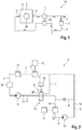
- the Fig. 1 shows a motor vehicle 19 with an internal combustion engine 2.
- the motor vehicle 19 comprises an internal combustion engine 2 with an inlet side 3 and an outlet side 4, which are connected to one another via at least one combustion chamber 23.
- the outlet side 4 and the inlet side 3 are additionally connected to one another via a low-pressure exhaust gas recirculation line 5, via which an exhaust gas can be conveyed from the outlet side 4 back to the inlet side 3.
- the internal combustion engine 2 further comprises an exhaust gas turbocharger 22.
- Fig. 2 shows a cooling circuit arrangement 1.
- the low-pressure exhaust gas recirculation line 5 is arranged in a thermally conductive connection with a first heat exchanger 6 of the cooling circuit arrangement 1 to dissipate thermal energy from the exhaust gas routed via the low-pressure exhaust gas recirculation line 5.
- the cooling circuit arrangement 1 has a first partial cooling circuit 7 and a second partial cooling circuit 8.
- the second partial cooling circuit 8 at least one second heat exchanger 12 and a second pump 13 for conveying a cooling fluid 10 through the second partial cooling circuit 8 are arranged to control the temperature of other components 11 of the internal combustion engine 2.
- the first partial cooling circuit 7 and the second partial cooling circuit 8 can be fluidically connected and separated from one another as a function of an operating state 14, 15 of the cooling circuit arrangement 1.
- the first partial cooling circuit 7 there are no further heat exchangers via which a component 11 other than the low-pressure exhaust gas recirculation line 5 and the cooling fluid 10 circulating in the first partial cooling circuit 7 can be tempered.
- a third heat exchanger 17 is arranged, the thermal energy between the first partial cooling circuit 4 and a further partial cooling circuit 8, here z. B. the second partial cooling circuit 8, the cooling circuit arrangement 1 transmits.
- the third heat exchanger 17 serves to transfer heat to the first partial cooling circuit 7 or to the cooling fluid 10 as early as possible, that is to say to control the temperature of the cooling fluid 10 circulating in the first partial cooling circuit 7.
- a heating device 16 which can be operated independently of an exhaust gas temperature, is arranged in the first partial cooling circuit 7 for controlling the temperature of the cooling fluid 10 circulating in the first partial cooling circuit 7.
- the heating device 16 is arranged directly upstream of the third heat exchanger 17. However, it is also possible for the heating device 16 to be arranged directly upstream or downstream of the first heat exchanger 6 or at another point in the first partial cooling circuit 7.
- the first partial cooling circuit 7 and the second partial cooling circuit 8 can be operated separately from one another in a first operating state 14 (see the present switching position of the switching element 20), with the cooling fluid 10 conveyed in the first partial cooling circuit 7 having a temperature below a limit temperature in the first operating state 14 18 lies.
- the first partial cooling circuit 7 and the second partial cooling circuit 8 are fluidically connected to one another in a second operating state 15 (see alternative switching position of the switching element 20), so that the cooling fluid 10 is via at least one pump 9, 13, i.e. the first pump 9 or the second pump 13 , through both partial cooling circuits 7, 8 can be conveyed.
- the fluid-technical separation or connection of the partial cooling circuits 7, 8 takes place via a switching element 20, here a valve controlled by a control unit 21 of the cooling circuit arrangement 1 or the internal combustion engine 2.
- the limit temperature 18 at which the switching element 20 is switched is stored in the control device 21.
Landscapes
- Engineering & Computer Science (AREA)
- Chemical & Material Sciences (AREA)
- Combustion & Propulsion (AREA)
- Mechanical Engineering (AREA)
- General Engineering & Computer Science (AREA)
- Chemical Kinetics & Catalysis (AREA)
- Exhaust-Gas Circulating Devices (AREA)
Abstract
Description
- Die Erfindung betrifft eine Kühlkreislaufanordnung einer Verbrennungskraftmaschine, insbesondere eines Kraftfahrzeuges.
- Eine Verbrennungskraftmaschine umfasst zumindest eine Einlassseite und eine Auslassseite, die über mindestens eine Brennkammer miteinander verbunden sind. Die Auslassseite und die Einlassseite können zusätzlich über eine Niederdruck-Abgasrückführungsleitung miteinander verbunden sein, über die ein Abgas von der Auslassseite zurück zur Einlassseite förderbar ist. Die Niederdruck-Abgasrückführungsleitung kann in wärmeleitender Verbindung mit einem ersten Wärmetauscher der Kühlkreislaufanordnung angeordnet sein zur Ableitung von Wärmeenergie aus dem über die Niederdruck-Abgasrückführungsleitung geführten Abgas.
- Eine Niederdruck-Abgasrückführung dient insbesondere der Reduzierung von Emissionen der Verbrennungskraftmaschine.
- Eine Verbrennungskraftmaschine umfasst regelmäßig einen oder mehrere Kühlkreisläufe als Kühlkreislaufanordnung, z. B. einen Hochtemperaturkreislauf (hohe Wärmeabgabekapazität) und einen Niedertemperaturkreislauf (geringere Wärmeabgabekapazität). In jedem Kühlkreislauf ist zumindest eine Pumpe angeordnet.
- Die einzelnen Kühlkreisläufe sind, wenn separate Pumpen vorgesehen sind, in der Regel fluidtechnisch voneinander getrennt angeordnet. Dabei können die Kühlkreisläufe aber über einen gemeinsamen Ausgleichbehälter verbunden sein, so dass ein Austausch eines gemeinsam genutzten Kühlfluids über den Ausgleichbehälter möglich sein kann. Die Trennung der Kühlkreisläufe ist erforderlich, um eine hinsichtlich der vorgesehenen Betriebstemperatur wirksame Trennung in Niedertemperatur- und Hochtemperaturkreislauf zu ermöglichen.
- Für eine Niederdruck-Abgasrückführungsleitung ist regelmäßig ein AGR-Kühler vorgesehen (im Folgenden als erster Wärmetauscher bezeichnet), durch den das rückgeführte Abgas im Betrieb der Verbrennungskraftmaschine abkühlbar ist. Gerade bei Kaltstartbedingungen, also bei einer Inbetriebnahme der Verbrennungskraftmaschine, sind die einzelnen Komponenten der Verbrennungskraftmaschine noch kalt, so dass das über die Niederdruck-Abgasrückführungsleitung rückgeführte Abgas stark abgekühlt wird. Da das Abgas einen gegenüber Umgebungsluft erhöhten Wassergehalt aufweist, kann Wasser z. B. in der Abgasrückführungsleitung kondensieren.
- Das so gebildete Kondensat ist insbesondere problematisch, wenn die Verbrennungskraftmaschine einen Turbolader bzw. einen Kompressor aufweist. Die mit hohen Geschwindigkeiten rotierenden Komponenten können bei Kontakt mit den Wassertropfen mechanisch geschädigt werden. Weiter kann Kondenswasser aber auch zu Fehlzündungen bei Ottomotoren führen.
- Um die Bildung von zu viel Kondensat bzw. von zu großen Tropfen zu unterbinden, wird Abgas erst dann über die Abgasrückführungsleitung hin zur Einlassseite geleitet, wenn die beteiligten Komponenten eine entsprechende Mindesttemperatur erreicht haben. Insbesondere erfolgt eine Freigabe für die Niederdruck-Abgasrückführungsleitung, wenn das den ersten Wärmetauscher beaufschlagende Kühlfluid eine Grenztemperatur erreicht hat.
- Aus der
DE 10 2018 210 572 A1 ist ein Niederdruckabgasrückführungssystem bekannt, wobei ein Wärmespeicher zur Temperierung des AGR-Kühlers vorgesehen ist. Der Wärmespeicher soll bei einem Kaltstart ggf. verfügbare Restwärme zur Temperierung des AGR-Kühlers bereitstellen. - Aufgabe der vorliegenden Erfindung ist es, die mit Bezug auf den Stand der Technik angeführten Probleme zumindest teilweise zu lösen. Insbesondere soll eine Kühlkreislaufanordnung vorgeschlagen werden, mit der z. B. nach einem Kaltstart möglichst frühzeitig eine Freigabe der Niederdruck-Abgasrückführungsleitung erfolgen kann.
- Zur Lösung dieser Aufgaben trägt eine Kühlkreislaufanordnung mit den Merkmalen gemäß Patentanspruch 1 bei. Vorteilhafte Weiterbildungen sind Gegenstand der abhängigen Patentansprüche. Die in den Patentansprüchen einzeln aufgeführten Merkmale sind in technologisch sinnvoller Weise miteinander kombinierbar und können durch erläuternde Sachverhalte aus der Beschreibung und/oder Details aus den Figuren ergänzt werden, wobei weitere Ausführungsvarianten der Erfindung aufgezeigt werden.
- Es wird eine Kühlkreislaufanordnung einer Verbrennungskraftmaschine, insbesondere eines Kraftfahrzeuges, vorgeschlagen. Die Verbrennungskraftmaschine weist zumindest eine Einlassseite und eine Auslassseite auf, die über mindestens eine Brennkammer miteinander verbunden sind. Die Auslassseite und die Einlassseite sind zusätzlich über eine Niederdruck-Abgasrückführungsleitung miteinander verbunden, über die ein Abgas von der Auslassseite zurück zur Einlassseite förderbar ist. Die Niederdruck-Abgasrückführungsleitung ist in wärmeleitender Verbindung mit einem ersten Wärmetauscher der Kühlkreislaufanordnung angeordnet zur Ableitung von Wärmeenergie aus dem über die Niederdruck-Abgasrückführungsleitung geführten Abgas. Die Kühlkreislaufanordnung weist zumindest einen ersten Teilkühlkreislauf und einen zweiten Teilkühlkreislauf auf; wobei in dem ersten Teilkühlkreislauf zumindest der erste Wärmetauscher und eine erste Pumpe zur Förderung eines Kühlfluids durch den ersten Teilkühlkreislauf angeordnet sind. In dem zweiten Teilkühlkreislauf sind zur Temperierung anderer Komponenten der Verbrennungskraftmaschine zumindest ein zweiter Wärmetauscher und eine zweite Pumpe zur Förderung eines Kühlfluids durch den zweiten Teilkühlkreislauf angeordnet. Der erste Teilkühlkreislauf und der zweite Teilkühlkreislauf sind in Abhängigkeit von einem Betriebszustand der Kühlkreislaufanordnung fluidtechnisch verbindbar und voneinander trennbar.
- Insbesondere dient der erste Wärmetauscher der Kühlung bzw. Temperierung der Niederdruck-Abgasrückführungsleitung. Im Betrieb der Verbrennungskraftmaschine wird das über die Niederdruck-Abgasrückführungsleitung geleitete Abgas in der Regel abgekühlt. Gerade nach einem Kaltstart ist es jedoch erforderlich, dass der erste Wärmetauscher möglichst schnell eine Mindesttemperatur erreicht hat, so dass zumindest eine Kondensation des im Abgas enthaltenden Wassers an den Wandungen des ersten Wärmetauschers verhindert werden kann. Weiter soll verhindert werden, dass das rückgeführte Abgas durch den noch kalten ersten Wärmetauscher so weit abgekühlt wird, dass sich Kondensat im Abgasstrom bildet.
- Mit der vorliegenden zumindest zeitweisen Trennung der Teilkühlkreisläufe soll insbesondere ermöglicht werden, dass das dann geringere Volumen an Kühlfluid, nämlich nur das in dem ersten Teilkühlkreislauf zirkulierende Volumen des Kühlfluids (ohne Leitungen hin zum Ausgleichbehälter), möglichst schnell erwärmt wird.
- Insbesondere sind in dem ersten Teilkühlkreislauf keine weiteren Wärmetauscher angeordnet, über die eine andere Komponente als die Niederdruck-Abgasrückführungsleitung und das in dem ersten Teilkühlkreislauf zirkulierende Fluid temperiert werden können.
- Insbesondere werden die den ersten Teilkühlkreislauf mit einem Ausgleichbehälter verbindenden Leitungen hier nicht berücksichtigt, d. h. der erste Teilkühlkreislauf kann mit einem Ausgleichbehälter verbunden sein, wobei das in diesen Leitungen vorliegende Volumen an Kühlfluid nicht berücksichtigt wird.
- Vorliegend bedeutet fluidtechnisch trennbar bzw. getrennt, dass ein Kühlfluid nicht von einem Teilkühlkreislauf in den anderen Teilkühlkreislauf übertreten kann. Dabei kann ein Austausch von Kühlfluid über einen Ausgleichbehälter insbesondere jederzeit erfolgen. D. h., dass ein Austausch von Kühlfluid über den Ausgleichbehälter hier nicht berücksichtigt wird.
- Der zweite Teilkühlkreislauf ist z. B. ein für die Verbrennungskraftmaschine (d. h. zumindest für eine der folgenden Komponenten: Zylinderkopf, Kurbelgehäuse, Ölkühler, etc.) vorgesehener Kühlkreislauf, insbesondere ein Hochtemperatur-Kühlkreislauf. Ggf. können weitere Teilkühlkreisläufe vorgesehen sein, z. B. Niedertemperaturkühlkreisläufe. Insbesondere können in diesem weiteren Teilkühlkreislauf weitere Komponenten, z. B. Kühler für Abgasbehandlungseinrichtungen, Ladeluftkühler, Generatorkühler, etc. angeordnet sein.
- Insbesondere ist in dem ersten Teilkühlkreislauf eine von einer Abgastemperatur unabhängig betreibbare Heizvorrichtung zur Temperierung des, insbesondere im ersten Teilkühlkreislauf zirkulierenden, Kühlfluids angeordnet.
- Über die Heizvorrichtung kann das Kühlfluid insbesondere unabhängig vom Abgas, und damit insbesondere schneller, aufgewärmt werden.
- Die Heizvorrichtung weist insbesondere eine Heizleistung von mindestens 500 Watt auf, insbesondere von mindestens 1 Kilowatt, bevorzugt von mindestens 10 Kilowatt.
- Insbesondere ist die Heizvorrichtung ein elektrisches Heizelement. Es können aber auch andere Formen von Heizvorrichtungen, z. B. Brenner, eingesetzt werden.
- Der Betrieb der Heizvorrichtung kann insbesondere auch unabhängig von einem Betrieb der Verbrennungskraftmaschine erfolgen. Insbesondere kann also das Kühlfluid bereits durch die Heizvorrichtung erwärmt werden, bevor die Verbrennungskraftmaschine in Betrieb genommen wird. Dabei kann das Kühlfluid in dem ersten Teilkühlkreislauf bereits durch die erste Pumpe gefördert werden. Es ist aber auch möglich, dass zumindest zeitweise die erste Pumpe nicht betrieben wird, so dass die Heizvorrichtung das nicht zirkulierende Kühlfluid bereits erwärmt.
- Insbesondere kann die Trennung der Teilkühlkreisläufe ebenfalls unabhängig vom Betrieb der Verbrennungskraftmaschine erfolgen. Insbesondere sind die Teilkühlkreisläufe immer dann getrennt, wenn die Verbrennungskraftmaschine nicht betrieben wird. Insbesondere sind die Teilkühlkreisläufe nur dann getrennt, wenn das in dem ersten Teilkühlkreislauf zirkulierende oder befindliche Kühlfluid eine Grenztemperatur unterschreitet.
- Insbesondere ist die Heizvorrichtung unmittelbar stromaufwärts des ersten Wärmetauschers angeordnet ist. Es ist aber auch möglich, dass die Heizvorrichtung unmittelbar stromabwärts des ersten Wärmetauschers oder an anderer Stelle im ersten Teilkühlkreislauf angeordnet ist.
- Insbesondere ist in dem ersten Teilkühlkreislauf (nur noch) ein dritter Wärmetauscher angeordnet, der Wärmeenergie zwischen dem ersten Teilkühlkreislauf und einem weiteren Teilkühlkreislauf der Kühlkreislaufanordnung überträgt. Der weitere Teilkühlkreislauf kann z. B. der zweite Teilkühlkreislauf oder ein weiterer Teilkühlkreislauf, z. B. ein Niedertemperatur-Kühlkreislauf, sein. Der dritte Wärmetauscher kann insbesondere dazu dienen, Wärme möglichst frühzeitig auf den ersten Teilkühlkreislauf zu übertragen. Ggf. kann ein Bypass für den dritten Wärmetauscher vorgesehen sein, so dass je nach Betriebszustand eine Ableitung von Wärme aus dem ersten Teilkühlkreislauf verhindert wird.
- Insbesondere weist der in einem ersten Betriebszustand von dem zweiten Teilkühlkreislauf getrennt betriebene erste Teilkühlkreislauf ein, insbesondere bei Betrieb der ersten Pumpe zirkulierendes, erstes Volumen des Kühlfluids von höchstens drei Litern, bevorzugt von höchstens zwei Litern, besonders bevorzugt von höchstens 1,5 Litern oder sogar von höchstens einem Liter auf.
- Insbesondere wird dabei das den ersten Teilkühlkreislauf mit einem Ausgleichbehälter verbindende Volumen von Leitungen nicht berücksichtigt.
- Infolge der zumindest zeitweisen Trennung des ersten Teilkühlkreislauf von anderen Teilkühlkreisläufen kann die Menge an Kühlfluid, die möglichst schnell erwärmt werden soll, deutlich reduziert werden. Damit kann auch z. B. eine Heizvorrichtung kleiner ausgelegt bzw. eine ausreichende Temperierung des ersten Wärmetauschers schneller erreicht werden.
- Insbesondere sind der erste Teilkühlkreislauf und der zweite Teilkühlkreislauf in einem ersten Betriebszustand getrennt voneinander betreibbar, wobei in dem ersten Betriebszustand das in dem ersten Teilkühlkreislauf geförderte Kühlfluid eine Temperatur aufweist, die unterhalb einer Grenztemperatur liegt.
- Insbesondere sind der erste Teilkühlkreislauf und der zweite Teilkühlkreislauf in einem zweiten Betriebszustand fluidtechnisch miteinander verbunden, so dass das Kühlfluid über zumindest eine Pumpe, also die erste Pumpe oder die zweite Pumpe, durch beide Teilkühlkreisläufe förderbar ist.
- Insbesondere wird dabei eine Verbindung über einen Ausgleichbehälter oder eine Verbindung über die Teilkühlkreisläufe mit dem Ausgleichbehälter verbindende Leitungen nicht berücksichtigt.
- Die Grenztemperatur bezeichnet insbesondere eine Temperatur des Kühlfluids, bei der die Bildung von Kondensat im Abgasstrom bzw. an den Wandungen des ersten Wärmetauschers oder des dritten Wärmetauschers verhindert werden kann.
- Insbesondere kann die fluidtechnische Trennung bzw. Verbindung der Teilkühlkreisläufe über ein Schaltelement erfolgen, z. B. über ein temperaturabhängig schaltendes Schaltelement oder durch ein von einem Steuergerät der Kühlkreislaufanordnung oder der Verbrennungskraftmaschine gesteuertes Schaltelement.
- Ein temperaturabhängig schaltendes Schaltelement ist z. B. ein Thermostat, ein Bimetall oder eine Formgedächtnislegierung. Ein gesteuertes Schaltelement umfasst z. B. ein Schaltventil oder ähnliches.
- Es wird weiter ein Verfahren zum Betrieb der beschriebenen Kühlkreislaufanordnung vorgeschlagen. Das Verfahren umfasst zumindest die folgenden Schritte:
- a) Bestimmen einer Temperatur des in dem ersten Teilkühlkreislauf geförderten Kühlfluids; und
wenn die Temperatur unterhalb einer Grenztemperatur liegt, - b) Trennen des ersten Teilkühlkreislaufs von dem zweiten Teilkühlkreislauf und
- c) Betreiben der ersten Pumpe zur Förderung des Kühlfluids ausschließlich durch den ersten Teilkühlkreislauf; oder
wenn die Temperatur mindestens die Grenztemperatur aufweist, - d) Verbinden des ersten Teilkühlkreislaufs und des zweiten Teilkühlkreislaufs und Betreiben zumindest einer der Pumpen zur Förderung des Kühlfluids durch die Teilkühlkreisläufe.
- Die obige (nicht abschließende) Einteilung der Verfahrensschritte in a) bis d) soll vorrangig nur zur Unterscheidung dienen und keine Reihenfolge und/oder Abhängigkeit erzwingen. Auch die Häufigkeit der Verfahrensschritte z. B. während der Einrichtung und/oder des Betriebes der Kühlkreislaufanordnung kann variieren. Ebenso ist möglich, dass Verfahrensschritte einander zumindest teilweise zeitlich überlagern. Ganz besonders bevorzugt finden die Verfahrensschritte b) und c) sowie d) jeweils nach Schritt a) statt. Insbesondere werden die Schritte b) und c) einerseits und d) andererseits jeweils in Abhängigkeit von Schritt a) durchgeführt. Schritte b) und c) einerseits und Schritt d) andererseits sind insbesondere bedingt und werden ggf. nur dann ausgeführt, wenn Schritt a) ein bestimmtes Ergebnis liefert.
- Insbesondere ist in dem ersten Teilkühlkreislauf eine von einer Abgastemperatur unabhängig betreibbare Heizvorrichtung zur Temperierung des Kühlfluids angeordnet. In Schritt c) wird das in dem ersten Teilkühlkreislauf befindliche Kühlfluid durch die Heizvorrichtung erwärmt.
- Insbesondere wird die Heizvorrichtung nur dann betrieben, wenn die Teilkühlkreisläufe getrennt voneinander sind.
- Es wird weiter ein Kraftfahrzeug vorgeschlagen, zumindest umfassend eine Verbrennungskraftmaschine und die beschriebene Kühlkreislaufanordnung. Die Kühlkreislaufanordnung ist mit dem beschriebenen Verfahren betreibbar, wobei die Trennung und Verbindung der Teilkühlkreisläufe selbsttätig durch ein temperaturabhängig schaltendes Schaltelement oder durch ein von einem Steuergerät gesteuertes Schaltelement erfolgt.
- Die Ausführungen zur Kühlkreislaufanordnung sind insbesondere auf das Verfahren und das Kraftfahrzeug übertragbar und jeweils umgekehrt.
- Es wird weiter ein Steuergerät vorgeschlagen, das zur Durchführung des beschriebenen Verfahrens ausgestattet, konfiguriert oder programmiert ist.
- Weiter kann das Verfahren auch von einem Computer bzw. mit einem Prozessor einer Steuereinheit ausgeführt werden.
- Es wird demnach auch ein System zur Datenverarbeitung vorgeschlagen, das einen Prozessor umfasst, der so angepasst/konfiguriert ist, dass er das Verfahren bzw. einen Teil der Schritte des vorgeschlagenen Verfahrens durchführt.
- Es kann ein computerlesbares Speichermedium vorgesehen sein, das Befehle umfasst, die bei der Ausführung durch einen Computer/Prozessor diesen veranlassen, das Verfahren bzw. mindestens einen Teil der Schritte des vorgeschlagenen Verfahrens auszuführen.
- Die Ausführungen zu der Kühlkreislaufanordnung sind insbesondere auf das Verfahren, das Kraftfahrzeug und/oder das computerimplementierte Verfahren (also den Computer bzw. den Prozessor, das Steuergerät, das System zur Datenverarbeitung, das computerlesbare Speichermedium) übertragbar und umgekehrt.
- Die Verwendung unbestimmter Artikel ("ein", "eine", "einer" und "eines"), insbesondere in den Patentansprüchen und der diese wiedergebenden Beschreibung, ist als solche und nicht als Zahlwort zu verstehen. Entsprechend damit eingeführte Begriffe bzw. Komponenten sind somit so zu verstehen, dass diese mindestens einmal vorhanden sind und insbesondere aber auch mehrfach vorhanden sein können.
- Vorsorglich sei angemerkt, dass die hier verwendeten Zahlwörter ("erste", "zweite", ...) vorrangig (nur) zur Unterscheidung von mehreren gleichartigen Gegenständen, Größen oder Prozessen dienen, also insbesondere keine Abhängigkeit und/oder Reihenfolge dieser Gegenstände, Größen oder Prozesse zueinander zwingend vorgeben. Sollte eine Abhängigkeit und/oder Reihenfolge erforderlich sein, ist dies hier explizit angegeben oder es ergibt sich offensichtlich für den Fachmann beim Studium der konkret beschriebenen Ausgestaltung. Soweit ein Bauteil mehrfach vorkommen kann ("mindestens ein"), kann die Beschreibung zu einem dieser Bauteile für alle oder ein Teil der Mehrzahl dieser Bauteile gleichermaßen gelten, dies ist aber nicht zwingend.
- Die Erfindung sowie das technische Umfeld werden nachfolgend anhand der beiliegenden Figuren näher erläutert. Es ist darauf hinzuweisen, dass die Erfindung durch die angeführten Ausführungsbeispiele nicht beschränkt werden soll. Insbesondere ist es, soweit nicht explizit anders dargestellt, auch möglich, Teilaspekte der in den Figuren erläuterten Sachverhalte zu extrahieren und mit anderen Bestandteilen und Erkenntnissen aus der vorliegenden Beschreibung zu kombinieren. Insbesondere ist darauf hinzuweisen, dass die Figuren und insbesondere die dargestellten Größenverhältnisse nur schematisch sind. Es zeigen:
- Fig. 1:
- ein Kraftfahrzeug mit einer Verbrennungskraftmaschine; und
- Fig. 2:
- eine Kühlkreislaufanordnung.
- Die
Fig. 1 zeigt ein Kraftfahrzeug 19 mit einer Verbrennungskraftmaschine 2. Das Kraftfahrzeug 19 umfasst eine Verbrennungskraftmaschine 2 mit einer Einlassseite 3 und eine Auslassseite 4, die über mindestens eine Brennkammer 23 miteinander verbunden sind. Die Auslassseite 4 und die Einlassseite 3 sind zusätzlich über eine Niederdruck-Abgasrückführungsleitung 5 miteinander verbunden, über die ein Abgas von der Auslassseite 4 zurück zur Einlassseite 3 förderbar ist. Die Verbrennungskraftmaschine 2 umfasst weiter einen Abgasturbolader 22. -
Fig. 2 zeigt eine Kühlkreislaufanordnung 1. Die Niederdruck-Abgasrückführungsleitung 5 ist in wärmeleitender Verbindung mit einem ersten Wärmetauscher 6 der Kühlkreislaufanordnung 1 angeordnet zur Ableitung von Wärmeenergie aus dem über die Niederdruck-Abgasrückführungsleitung 5 geführten Abgas. Die Kühlkreislaufanordnung 1 weist einen ersten Teilkühlkreislauf 7 und einen zweiten Teilkühlkreislauf 8 auf. In dem ersten Teilkühlkreislauf 7 sind zumindest der erste Wärmetauscher 6 und eine erste Pumpe 9 zur Förderung eines Kühlfluids 10 durch den ersten Teilkühlkreislauf 7 angeordnet. In dem zweiten Teilkühlkreislauf 8 sind zur Temperierung anderer Komponenten 11 der Verbrennungskraftmaschine 2 zumindest ein zweiter Wärmetauscher 12 und eine zweite Pumpe 13 zur Förderung eines Kühlfluids 10 durch den zweiten Teilkühlkreislauf 8 angeordnet. Der erste Teilkühlkreislauf 7 und der zweite Teilkühlkreislauf 8 sind in Abhängigkeit von einem Betriebszustand 14, 15 der Kühlkreislaufanordnung 1 fluidtechnisch verbindbar und voneinander trennbar. - In dem ersten Teilkühlkreislauf 7 sind keine weiteren Wärmetauscher angeordnet, über die eine andere Komponente 11 als die Niederdruck-Abgasrückführungsleitung 5 und das in dem ersten Teilkühlkreislauf 7 zirkulierende Kühlfluid 10 temperiert werden können. In dem ersten Teilkühlkreislauf 7 ist aber ein dritter Wärmetauscher 17 angeordnet, der Wärmeenergie zwischen dem ersten Teilkühlkreislauf 4 und einem weiteren Teilkühlkreislauf 8, hier z. B. dem zweiten Teilkühlkreislauf 8, der Kühlkreislaufanordnung 1 überträgt. Der dritte Wärmetauscher 17 dient dazu, Wärme möglichst frühzeitig auf den ersten Teilkühlkreislauf 7 bzw. auf das Kühlfluid 10 zu übertragen, also in dem ersten Teilkühlkreislauf 7 zirkulierendes Kühlfluid 10 zu temperieren.
- In dem ersten Teilkühlkreislauf 7 ist eine von einer Abgastemperatur unabhängig betreibbare Heizvorrichtung 16 zur Temperierung des im ersten Teilkühlkreislauf 7 zirkulierenden Kühlfluids 10 angeordnet.
- Die Heizvorrichtung 16 ist unmittelbar stromaufwärts des dritten Wärmetauschers 17 angeordnet. Es ist aber auch möglich, dass die Heizvorrichtung 16 unmittelbar stromaufwärts oder stromabwärts des ersten Wärmetauschers 6 oder an anderer Stelle im ersten Teilkühlkreislauf 7 angeordnet ist.
- Der erste Teilkühlkreislauf 7 und der zweite Teilkühlkreislauf 8 sind in einem ersten Betriebszustand 14 (siehe vorliegende Schaltstellung des Schaltelements 20) getrennt voneinander betreibbar, wobei in dem ersten Betriebszustand 14 das in dem ersten Teilkühlkreislauf 7 geförderte Kühlfluid 10 eine Temperatur aufweist, die unterhalb einer Grenztemperatur 18 liegt.
- Der erste Teilkühlkreislauf 7 und der zweite Teilkühlkreislauf 8 sind in einem zweiten Betriebszustand 15 (siehe alternative Schaltstellung des Schaltelements 20) fluidtechnisch miteinander verbunden, so dass das Kühlfluid 10 über zumindest eine Pumpe 9, 13, also die erste Pumpe 9 oder die zweite Pumpe 13, durch beide Teilkühlkreisläufe 7, 8 förderbar ist.
- Die fluidtechnische Trennung bzw. Verbindung der Teilkühlkreisläufe 7, 8 erfolgt über ein Schaltelement 20, hier ein von einem Steuergerät 21 der Kühlkreislaufanordnung 1 oder der Verbrennungskraftmaschine 2 gesteuertes Ventil. In dem Steuergerät 21 ist die Grenztemperatur 18 hinterlegt, bei der eine Schaltung des Schaltelements 20 erfolgt.
-
- 1
- Kühlkreislaufanordnung
- 2
- Verbrennungskraftmaschine
- 3
- Einlassseite
- 4
- Auslassseite
- 5
- Niederdruck-Abgasrückführungsleitung
- 6
- erster Wärmetauscher
- 7
- erster Teilkühlkreislauf
- 8
- zweiter Teilkühlkreislauf
- 9
- erste Pumpe
- 10
- Kühlfluid
- 11
- Komponente
- 12
- zweiter Wärmetauscher
- 13
- zweite Pumpe
- 14
- erster Betriebszustand
- 15
- zweiter Betriebszustand
- 16
- Heizvorrichtung
- 17
- dritter Wärmetauscher
- 18
- Grenztemperatur
- 19
- Kraftfahrzeug
- 20
- Schaltelement
- 21
- Steuergerät
- 22
- Abgasturbolader
- 23
- Brennkammer
Claims (10)
- Kühlkreislaufanordnung (1) einer Verbrennungskraftmaschine (2), wobei die Verbrennungskraftmaschine (2) zumindest eine Einlassseite (3) und eine Auslassseite (4) aufweist, die über mindestens eine Brennkammer (23) miteinander verbunden sind, wobei die Auslassseite (4) und die Einlassseite (3) zusätzlich über eine Niederdruck-Abgasrückführungsleitung (5) miteinander verbunden sind, über die ein Abgas von der Auslassseite (4) zurück zur Einlassseite (3) förderbar ist, wobei die Niederdruck-Abgasrückführungsleitung (5) in wärmeleitender Verbindung mit einem ersten Wärmetauscher (6) der Kühlkreislaufanordnung (1) angeordnet ist zur Ableitung von Wärmeenergie aus dem über die Niederdruck-Abgasrückführungsleitung (5) geführten Abgas; wobei die Kühlkreislaufanordnung (1) zumindest einen ersten Teilkühlkreislauf (7) und einen zweiten Teilkühlkreislauf (8) aufweist; wobei in dem ersten Teilkühlkreislauf (7) zumindest der erste Wärmetauscher (6) und eine erste Pumpe (9) zur Förderung eines Kühlfluids (10) durch den ersten Teilkühlkreislauf (7) angeordnet sind; wobei in dem zweiten Teilkühlkreislauf (8) zur Temperierung anderer Komponenten (11) der Verbrennungskraftmaschine (2) zumindest ein zweiter Wärmetauscher (12) und eine zweite Pumpe (13) zur Förderung eines Kühlfluids (10) durch den zweiten Teilkühlkreislauf (8) angeordnet sind; wobei der erste Teilkühlkreislauf (7) und der zweite Teilkühlkreislauf (8) in Abhängigkeit von einem Betriebszustand (14, 15) der Kühlkreislaufanordnung (1) fluidtechnisch verbindbar und voneinander trennbar sind.
- Kühlkreislaufanordnung (1) nach Patentanspruch 1, wobei in dem ersten Teilkühlkreislauf (7) eine von einer Abgastemperatur unabhängig betreibbare Heizvorrichtung (16) zur Temperierung des Kühlfluids (10) angeordnet ist.
- Kühlkreislaufanordnung (1) nach Patentanspruch 2, wobei die Heizvorrichtung (16) ein elektrisches Heizelement ist.
- Kühlkreislaufanordnung (1) nach einem der vorhergehenden Patentansprüche 2 und 3, wobei die Heizvorrichtung (16) unmittelbar stromaufwärts des ersten Wärmetauschers (6) angeordnet ist.
- Kühlkreislaufanordnung (1) nach einem der vorhergehenden Patentansprüche, wobei in dem ersten Teilkühlkreislauf (7) ein dritter Wärmetauscher (17) angeordnet ist, der Wärmeenergie zwischen dem ersten Teilkühlkreislauf (7) und einem weiteren Teilkühlkreislauf (8) der Kühlkreislaufanordnung (1) überträgt.
- Kühlkreislaufanordnung (1) nach einem der vorhergehenden Patentansprüche, wobei der in einem ersten Betriebszustand (14) von dem zweiten Teilkühlkreislauf (8) getrennt betriebene erste Teilkühlkreislauf (7) ein erstes Volumen des Kühlfluids (10) von höchstens drei Litern aufweist.
- Kühlkreislaufanordnung (1) nach einem der vorhergehenden Patentansprüche, wobei der erste Teilkühlkreislauf (7) und der zweite Teilkühlkreislauf (8) in einem ersten Betriebszustand (14) getrennt voneinander betreibbar sind, wobei in dem ersten Betriebszustand (14) das in dem ersten Teilkühlkreislauf (7) geförderte Kühlfluid (10) eine Temperatur aufweist, die unterhalb einer Grenztemperatur (18) liegt.
- Verfahren zum Betrieb einer Kühlkreislaufanordnung (1) nach einem der vorhergehenden Patentansprüche, zumindest umfassend die folgenden Schritte:a) Bestimmen einer Temperatur des in dem ersten Teilkühlkreislauf (7) geförderten Kühlfluids (10); und
wenn die Temperatur unterhalb einer Grenztemperatur (18) liegt,b) Trennen des ersten Teilkühlkreislaufs (7) von dem zweiten Teilkühlkreislauf (8) undc) Betreiben der ersten Pumpe (9) zur Förderung des Kühlfluids (10) ausschließlich durch den ersten Teilkühlkreislauf (7); oder
wenn die Temperatur mindestens die Grenztemperatur (18) aufweist,d) Verbinden des ersten Teilkühlkreislaufs (7) und des zweiten Teilkühlkreislaufs (8) und Betreiben zumindest einer der Pumpen (9, 13) zur Förderung des Kühlfluids (10) durch die Teilkühlkreisläufe (7, 8). - Verfahren nach Patentanspruch 8, wobei in dem ersten Teilkühlkreislauf (7) eine von einer Abgastemperatur unabhängig betreibbare Heizvorrichtung (16) zur Temperierung des Kühlfluids (10) angeordnet ist; wobei in Schritt c) das in dem ersten Teilkühlkreislauf (7) befindliche Kühlfluid (10) durch die Heizvorrichtung (16) erwärmt wird.
- Kraftfahrzeug (19), zumindest umfassend eine Verbrennungskraftmaschine (2) und eine Kühlkreislaufanordnung (1) nach einem der vorhergehenden Patentansprüche 1 bis 7; wobei die Kühlkreislaufanordnung (1) mit einem Verfahren nach einem der vorhergehenden Patentansprüche 8 und 9 betreibbar ist; wobei die Trennung und Verbindung der Teilkühlkreisläufe (7, 8) selbsttätig durch ein temperaturabhängig schaltendes Schaltelement (20) oder durch ein von einem Steuergerät (21) gesteuertes Schaltelement (20) erfolgt.
Applications Claiming Priority (1)
| Application Number | Priority Date | Filing Date | Title |
|---|---|---|---|
| DE102020115018.0A DE102020115018A1 (de) | 2020-06-05 | 2020-06-05 | Kühlkreislaufanordnung einer Verbrennungskraftmaschine |
Publications (2)
| Publication Number | Publication Date |
|---|---|
| EP3919726A1 true EP3919726A1 (de) | 2021-12-08 |
| EP3919726B1 EP3919726B1 (de) | 2024-07-10 |
Family
ID=75977688
Family Applications (1)
| Application Number | Title | Priority Date | Filing Date |
|---|---|---|---|
| EP21174420.6A Active EP3919726B1 (de) | 2020-06-05 | 2021-05-18 | Kühlkreislaufanordnung einer verbrennungskraftmaschine |
Country Status (2)
| Country | Link |
|---|---|
| EP (1) | EP3919726B1 (de) |
| DE (1) | DE102020115018A1 (de) |
Citations (3)
| Publication number | Priority date | Publication date | Assignee | Title |
|---|---|---|---|---|
| DE102017123468A1 (de) * | 2017-10-10 | 2019-04-11 | Volkswagen Aktiengesellschaft | Verfahren zum Betreiben einer Brennkraftmaschine, Brennkraftmaschine und Kraftfahrzeug |
| WO2019185663A1 (fr) * | 2018-03-27 | 2019-10-03 | Renault S.A.S | Circuit de refroidissement pour un moteur à combustion interne équipé d'un circuit de recirculation de gaz d'échappement et son procédé de commande |
| DE102018210572A1 (de) | 2018-06-28 | 2020-01-02 | Ford Global Technologies, Llc | Niederdruckabgasrückführungssystem, Kraftfahrzeug sowie Verfahren zur Temperierung eines AGR-Kühlers und/oder eines AGR-Ventils |
Family Cites Families (2)
| Publication number | Priority date | Publication date | Assignee | Title |
|---|---|---|---|---|
| DE102018101999A1 (de) | 2018-01-30 | 2019-08-01 | Volkswagen Aktiengesellschaft | Kühlkreislaufanordnung einer Verbrennungskraftmaschine und Verfahren zum Betrieb eines Kraftfahrzeuges |
| DE102019207000A1 (de) | 2019-05-14 | 2020-11-19 | Volkswagen Aktiengesellschaft | Kühlkreislaufanordnung einer Verbrennungskraftmaschine |
-
2020
- 2020-06-05 DE DE102020115018.0A patent/DE102020115018A1/de not_active Withdrawn
-
2021
- 2021-05-18 EP EP21174420.6A patent/EP3919726B1/de active Active
Patent Citations (3)
| Publication number | Priority date | Publication date | Assignee | Title |
|---|---|---|---|---|
| DE102017123468A1 (de) * | 2017-10-10 | 2019-04-11 | Volkswagen Aktiengesellschaft | Verfahren zum Betreiben einer Brennkraftmaschine, Brennkraftmaschine und Kraftfahrzeug |
| WO2019185663A1 (fr) * | 2018-03-27 | 2019-10-03 | Renault S.A.S | Circuit de refroidissement pour un moteur à combustion interne équipé d'un circuit de recirculation de gaz d'échappement et son procédé de commande |
| DE102018210572A1 (de) | 2018-06-28 | 2020-01-02 | Ford Global Technologies, Llc | Niederdruckabgasrückführungssystem, Kraftfahrzeug sowie Verfahren zur Temperierung eines AGR-Kühlers und/oder eines AGR-Ventils |
Also Published As
| Publication number | Publication date |
|---|---|
| DE102020115018A1 (de) | 2021-12-09 |
| EP3919726B1 (de) | 2024-07-10 |
Similar Documents
| Publication | Publication Date | Title |
|---|---|---|
| EP1570168B1 (de) | Vorrichtung zur kühlung | |
| DE60024390T2 (de) | Hochtemperaturkühlmittelkreislauf für Rückführvorrichtung von gekühltem Abgas für Brennkraftmaschinen | |
| EP1616087B1 (de) | Kreislaufanordnung zur kühlung von ladeluft und verfahren zum betreiben einer derartigen kreislaufanordnung | |
| DE102014201678B4 (de) | Ladeluftkühlersystem mit integrierter Aufheizeinrichtung | |
| EP1651846B1 (de) | Kreislaufanordnung zur kühlung von ladeluft und verfahren zum betreiben einer derartigen kreislaufanordnung | |
| DE102013206082A1 (de) | Vorrichtung und Verfahren für den Motorwarmlauf | |
| DE102012200562A1 (de) | Motorsystem | |
| DE102012223808B4 (de) | Brennkraftmaschine mit Abgasturboaufladung und Abgasrückführung und Verfahren zum Betreiben einer derartigen Brennkraftmaschine | |
| DE102010001752B4 (de) | Kühlsystem | |
| DE102011113315A1 (de) | Integriertes Kühlsystem für eine Abgasrückführung und Ladung | |
| EP3739180B1 (de) | Kühlkreislaufanordnung einer verbrennungskraftmaschine | |
| DE102018124160A1 (de) | Verbrennungskraftmaschine mit Ladeluftkühler | |
| EP3919726B1 (de) | Kühlkreislaufanordnung einer verbrennungskraftmaschine | |
| EP2652305B1 (de) | Kühlkreis für eine brennkraftmaschine mit einer abgasrückführung und verfahren zum betrieb einer brennkraftmaschine mit einem solchen kühlkreis | |
| EP3527800B1 (de) | Kühlkreislauf für eine antriebseinheit eines kraftfahrzeuges | |
| WO2008046490A1 (de) | Kühlkreislauf für eine brennkraftmaschine | |
| DE202013100932U1 (de) | Ladeluftkühlersystem mit integrierter Aufheizeinrichtung | |
| DE102013211156A1 (de) | Flüssigkeitsgekühlte Brennkraftmaschine mit Nebenkreislauf | |
| DE102018101999A1 (de) | Kühlkreislaufanordnung einer Verbrennungskraftmaschine und Verfahren zum Betrieb eines Kraftfahrzeuges | |
| DE102010036581A1 (de) | Flüssigkeitsgekühlte Brennkraftmaschine mit kühlmittelbetriebener Heizung und Verfahren zum Betreiben einer derartigen Brennkraftmaschine | |
| DE202015100531U1 (de) | Brennkraftmaschine mit Split Kühlsystem und Zylinderabschaltung | |
| EP1727976B1 (de) | Brennkraftmaschine mit befeuchtungseinrichtung und wärmetauscher | |
| EP2307678B1 (de) | Kühleinrichtung für eine kraftfahrzeug-brennkraftmaschine und verfahren zum betreiben derselben | |
| DE102013011563A1 (de) | Kühlkreislauf einer Brennkraftmaschine sowie Verfahren zum Betreiben eines Kühlkreislaufs | |
| EP3754166B1 (de) | Brennkraftmaschine mit einem einen agr-kühler umfassenden kühlsystem |
Legal Events
| Date | Code | Title | Description |
|---|---|---|---|
| PUAI | Public reference made under article 153(3) epc to a published international application that has entered the european phase |
Free format text: ORIGINAL CODE: 0009012 |
|
| STAA | Information on the status of an ep patent application or granted ep patent |
Free format text: STATUS: THE APPLICATION HAS BEEN PUBLISHED |
|
| AK | Designated contracting states |
Kind code of ref document: A1 Designated state(s): AL AT BE BG CH CY CZ DE DK EE ES FI FR GB GR HR HU IE IS IT LI LT LU LV MC MK MT NL NO PL PT RO RS SE SI SK SM TR |
|
| B565 | Issuance of search results under rule 164(2) epc |
Effective date: 20210705 |
|
| STAA | Information on the status of an ep patent application or granted ep patent |
Free format text: STATUS: REQUEST FOR EXAMINATION WAS MADE |
|
| 17P | Request for examination filed |
Effective date: 20220608 |
|
| RBV | Designated contracting states (corrected) |
Designated state(s): AL AT BE BG CH CY CZ DE DK EE ES FI FR GB GR HR HU IE IS IT LI LT LU LV MC MK MT NL NO PL PT RO RS SE SI SK SM TR |
|
| GRAP | Despatch of communication of intention to grant a patent |
Free format text: ORIGINAL CODE: EPIDOSNIGR1 |
|
| STAA | Information on the status of an ep patent application or granted ep patent |
Free format text: STATUS: GRANT OF PATENT IS INTENDED |
|
| RIC1 | Information provided on ipc code assigned before grant |
Ipc: F02M 26/35 20160101ALI20231121BHEP Ipc: F02M 26/28 20160101ALI20231121BHEP Ipc: F02M 26/23 20160101ALI20231121BHEP Ipc: F02M 26/06 20160101ALI20231121BHEP Ipc: F01P 3/20 20060101ALI20231121BHEP Ipc: F01P 3/12 20060101AFI20231121BHEP |
|
| INTG | Intention to grant announced |
Effective date: 20231212 |
|
| P01 | Opt-out of the competence of the unified patent court (upc) registered |
Effective date: 20240214 |
|
| GRAS | Grant fee paid |
Free format text: ORIGINAL CODE: EPIDOSNIGR3 |
|
| GRAA | (expected) grant |
Free format text: ORIGINAL CODE: 0009210 |
|
| STAA | Information on the status of an ep patent application or granted ep patent |
Free format text: STATUS: THE PATENT HAS BEEN GRANTED |
|
| AK | Designated contracting states |
Kind code of ref document: B1 Designated state(s): AL AT BE BG CH CY CZ DE DK EE ES FI FR GB GR HR HU IE IS IT LI LT LU LV MC MK MT NL NO PL PT RO RS SE SI SK SM TR |
|
| REG | Reference to a national code |
Ref country code: CH Ref legal event code: EP |
|
| REG | Reference to a national code |
Ref country code: DE Ref legal event code: R096 Ref document number: 502021004292 Country of ref document: DE |
|
| REG | Reference to a national code |
Ref country code: LT Ref legal event code: MG9D |
|
| REG | Reference to a national code |
Ref country code: NL Ref legal event code: MP Effective date: 20240710 |
|
| PG25 | Lapsed in a contracting state [announced via postgrant information from national office to epo] |
Ref country code: PT Free format text: LAPSE BECAUSE OF FAILURE TO SUBMIT A TRANSLATION OF THE DESCRIPTION OR TO PAY THE FEE WITHIN THE PRESCRIBED TIME-LIMIT Effective date: 20241111 |
|
| PG25 | Lapsed in a contracting state [announced via postgrant information from national office to epo] |
Ref country code: NL Free format text: LAPSE BECAUSE OF FAILURE TO SUBMIT A TRANSLATION OF THE DESCRIPTION OR TO PAY THE FEE WITHIN THE PRESCRIBED TIME-LIMIT Effective date: 20240710 |
|
| PG25 | Lapsed in a contracting state [announced via postgrant information from national office to epo] |
Ref country code: PT Free format text: LAPSE BECAUSE OF FAILURE TO SUBMIT A TRANSLATION OF THE DESCRIPTION OR TO PAY THE FEE WITHIN THE PRESCRIBED TIME-LIMIT Effective date: 20241111 Ref country code: NL Free format text: LAPSE BECAUSE OF FAILURE TO SUBMIT A TRANSLATION OF THE DESCRIPTION OR TO PAY THE FEE WITHIN THE PRESCRIBED TIME-LIMIT Effective date: 20240710 |
|
| PG25 | Lapsed in a contracting state [announced via postgrant information from national office to epo] |
Ref country code: NO Free format text: LAPSE BECAUSE OF FAILURE TO SUBMIT A TRANSLATION OF THE DESCRIPTION OR TO PAY THE FEE WITHIN THE PRESCRIBED TIME-LIMIT Effective date: 20241010 |
|
| PG25 | Lapsed in a contracting state [announced via postgrant information from national office to epo] |
Ref country code: FI Free format text: LAPSE BECAUSE OF FAILURE TO SUBMIT A TRANSLATION OF THE DESCRIPTION OR TO PAY THE FEE WITHIN THE PRESCRIBED TIME-LIMIT Effective date: 20240710 Ref country code: PL Free format text: LAPSE BECAUSE OF FAILURE TO SUBMIT A TRANSLATION OF THE DESCRIPTION OR TO PAY THE FEE WITHIN THE PRESCRIBED TIME-LIMIT Effective date: 20240710 Ref country code: GR Free format text: LAPSE BECAUSE OF FAILURE TO SUBMIT A TRANSLATION OF THE DESCRIPTION OR TO PAY THE FEE WITHIN THE PRESCRIBED TIME-LIMIT Effective date: 20241011 |
|
| PG25 | Lapsed in a contracting state [announced via postgrant information from national office to epo] |
Ref country code: BG Free format text: LAPSE BECAUSE OF FAILURE TO SUBMIT A TRANSLATION OF THE DESCRIPTION OR TO PAY THE FEE WITHIN THE PRESCRIBED TIME-LIMIT Effective date: 20240710 |
|
| PG25 | Lapsed in a contracting state [announced via postgrant information from national office to epo] |
Ref country code: LV Free format text: LAPSE BECAUSE OF FAILURE TO SUBMIT A TRANSLATION OF THE DESCRIPTION OR TO PAY THE FEE WITHIN THE PRESCRIBED TIME-LIMIT Effective date: 20240710 |
|
| PG25 | Lapsed in a contracting state [announced via postgrant information from national office to epo] |
Ref country code: IS Free format text: LAPSE BECAUSE OF FAILURE TO SUBMIT A TRANSLATION OF THE DESCRIPTION OR TO PAY THE FEE WITHIN THE PRESCRIBED TIME-LIMIT Effective date: 20241110 |
|
| PG25 | Lapsed in a contracting state [announced via postgrant information from national office to epo] |
Ref country code: HR Free format text: LAPSE BECAUSE OF FAILURE TO SUBMIT A TRANSLATION OF THE DESCRIPTION OR TO PAY THE FEE WITHIN THE PRESCRIBED TIME-LIMIT Effective date: 20240710 |
|
| PG25 | Lapsed in a contracting state [announced via postgrant information from national office to epo] |
Ref country code: ES Free format text: LAPSE BECAUSE OF FAILURE TO SUBMIT A TRANSLATION OF THE DESCRIPTION OR TO PAY THE FEE WITHIN THE PRESCRIBED TIME-LIMIT Effective date: 20240710 Ref country code: RS Free format text: LAPSE BECAUSE OF FAILURE TO SUBMIT A TRANSLATION OF THE DESCRIPTION OR TO PAY THE FEE WITHIN THE PRESCRIBED TIME-LIMIT Effective date: 20241010 |
|
| PG25 | Lapsed in a contracting state [announced via postgrant information from national office to epo] |
Ref country code: RS Free format text: LAPSE BECAUSE OF FAILURE TO SUBMIT A TRANSLATION OF THE DESCRIPTION OR TO PAY THE FEE WITHIN THE PRESCRIBED TIME-LIMIT Effective date: 20241010 Ref country code: PL Free format text: LAPSE BECAUSE OF FAILURE TO SUBMIT A TRANSLATION OF THE DESCRIPTION OR TO PAY THE FEE WITHIN THE PRESCRIBED TIME-LIMIT Effective date: 20240710 Ref country code: NO Free format text: LAPSE BECAUSE OF FAILURE TO SUBMIT A TRANSLATION OF THE DESCRIPTION OR TO PAY THE FEE WITHIN THE PRESCRIBED TIME-LIMIT Effective date: 20241010 Ref country code: LV Free format text: LAPSE BECAUSE OF FAILURE TO SUBMIT A TRANSLATION OF THE DESCRIPTION OR TO PAY THE FEE WITHIN THE PRESCRIBED TIME-LIMIT Effective date: 20240710 Ref country code: IS Free format text: LAPSE BECAUSE OF FAILURE TO SUBMIT A TRANSLATION OF THE DESCRIPTION OR TO PAY THE FEE WITHIN THE PRESCRIBED TIME-LIMIT Effective date: 20241110 Ref country code: HR Free format text: LAPSE BECAUSE OF FAILURE TO SUBMIT A TRANSLATION OF THE DESCRIPTION OR TO PAY THE FEE WITHIN THE PRESCRIBED TIME-LIMIT Effective date: 20240710 Ref country code: GR Free format text: LAPSE BECAUSE OF FAILURE TO SUBMIT A TRANSLATION OF THE DESCRIPTION OR TO PAY THE FEE WITHIN THE PRESCRIBED TIME-LIMIT Effective date: 20241011 Ref country code: FI Free format text: LAPSE BECAUSE OF FAILURE TO SUBMIT A TRANSLATION OF THE DESCRIPTION OR TO PAY THE FEE WITHIN THE PRESCRIBED TIME-LIMIT Effective date: 20240710 Ref country code: ES Free format text: LAPSE BECAUSE OF FAILURE TO SUBMIT A TRANSLATION OF THE DESCRIPTION OR TO PAY THE FEE WITHIN THE PRESCRIBED TIME-LIMIT Effective date: 20240710 Ref country code: BG Free format text: LAPSE BECAUSE OF FAILURE TO SUBMIT A TRANSLATION OF THE DESCRIPTION OR TO PAY THE FEE WITHIN THE PRESCRIBED TIME-LIMIT Effective date: 20240710 |
|
| REG | Reference to a national code |
Ref country code: DE Ref legal event code: R097 Ref document number: 502021004292 Country of ref document: DE |
|
| PG25 | Lapsed in a contracting state [announced via postgrant information from national office to epo] |
Ref country code: RO Free format text: LAPSE BECAUSE OF FAILURE TO SUBMIT A TRANSLATION OF THE DESCRIPTION OR TO PAY THE FEE WITHIN THE PRESCRIBED TIME-LIMIT Effective date: 20240710 Ref country code: DK Free format text: LAPSE BECAUSE OF FAILURE TO SUBMIT A TRANSLATION OF THE DESCRIPTION OR TO PAY THE FEE WITHIN THE PRESCRIBED TIME-LIMIT Effective date: 20240710 Ref country code: SM Free format text: LAPSE BECAUSE OF FAILURE TO SUBMIT A TRANSLATION OF THE DESCRIPTION OR TO PAY THE FEE WITHIN THE PRESCRIBED TIME-LIMIT Effective date: 20240710 |
|
| PG25 | Lapsed in a contracting state [announced via postgrant information from national office to epo] |
Ref country code: EE Free format text: LAPSE BECAUSE OF FAILURE TO SUBMIT A TRANSLATION OF THE DESCRIPTION OR TO PAY THE FEE WITHIN THE PRESCRIBED TIME-LIMIT Effective date: 20240710 |
|
| PG25 | Lapsed in a contracting state [announced via postgrant information from national office to epo] |
Ref country code: CZ Free format text: LAPSE BECAUSE OF FAILURE TO SUBMIT A TRANSLATION OF THE DESCRIPTION OR TO PAY THE FEE WITHIN THE PRESCRIBED TIME-LIMIT Effective date: 20240710 |
|
| PG25 | Lapsed in a contracting state [announced via postgrant information from national office to epo] |
Ref country code: SK Free format text: LAPSE BECAUSE OF FAILURE TO SUBMIT A TRANSLATION OF THE DESCRIPTION OR TO PAY THE FEE WITHIN THE PRESCRIBED TIME-LIMIT Effective date: 20240710 Ref country code: IT Free format text: LAPSE BECAUSE OF FAILURE TO SUBMIT A TRANSLATION OF THE DESCRIPTION OR TO PAY THE FEE WITHIN THE PRESCRIBED TIME-LIMIT Effective date: 20240710 |
|
| PLBE | No opposition filed within time limit |
Free format text: ORIGINAL CODE: 0009261 |
|
| STAA | Information on the status of an ep patent application or granted ep patent |
Free format text: STATUS: NO OPPOSITION FILED WITHIN TIME LIMIT |
|
| 26N | No opposition filed |
Effective date: 20250411 |
|
| PGFP | Annual fee paid to national office [announced via postgrant information from national office to epo] |
Ref country code: DE Payment date: 20250531 Year of fee payment: 5 |
|
| PGFP | Annual fee paid to national office [announced via postgrant information from national office to epo] |
Ref country code: GB Payment date: 20250520 Year of fee payment: 5 |
|
| PGFP | Annual fee paid to national office [announced via postgrant information from national office to epo] |
Ref country code: FR Payment date: 20250526 Year of fee payment: 5 |
|
| PGFP | Annual fee paid to national office [announced via postgrant information from national office to epo] |
Ref country code: AT Payment date: 20250721 Year of fee payment: 5 |
|
| PG25 | Lapsed in a contracting state [announced via postgrant information from national office to epo] |
Ref country code: SE Free format text: LAPSE BECAUSE OF FAILURE TO SUBMIT A TRANSLATION OF THE DESCRIPTION OR TO PAY THE FEE WITHIN THE PRESCRIBED TIME-LIMIT Effective date: 20240710 |
|
| REG | Reference to a national code |
Ref country code: CH Ref legal event code: H13 Free format text: ST27 STATUS EVENT CODE: U-0-0-H10-H13 (AS PROVIDED BY THE NATIONAL OFFICE) Effective date: 20251223 |
|
| PG25 | Lapsed in a contracting state [announced via postgrant information from national office to epo] |
Ref country code: LU Free format text: LAPSE BECAUSE OF NON-PAYMENT OF DUE FEES Effective date: 20250518 |
|
| PG25 | Lapsed in a contracting state [announced via postgrant information from national office to epo] |
Ref country code: CH Free format text: LAPSE BECAUSE OF NON-PAYMENT OF DUE FEES Effective date: 20250531 |
|
| REG | Reference to a national code |
Ref country code: BE Ref legal event code: MM Effective date: 20250531 |
|
| PG25 | Lapsed in a contracting state [announced via postgrant information from national office to epo] |
Ref country code: MC Free format text: LAPSE BECAUSE OF FAILURE TO SUBMIT A TRANSLATION OF THE DESCRIPTION OR TO PAY THE FEE WITHIN THE PRESCRIBED TIME-LIMIT Effective date: 20240710 |
|
| PG25 | Lapsed in a contracting state [announced via postgrant information from national office to epo] |
Ref country code: IE Free format text: LAPSE BECAUSE OF NON-PAYMENT OF DUE FEES Effective date: 20250518 |
|
| PG25 | Lapsed in a contracting state [announced via postgrant information from national office to epo] |
Ref country code: BE Free format text: LAPSE BECAUSE OF NON-PAYMENT OF DUE FEES Effective date: 20250531 |