EP3919662A1 - Loom - Google Patents
Loom Download PDFInfo
- Publication number
- EP3919662A1 EP3919662A1 EP21176616.7A EP21176616A EP3919662A1 EP 3919662 A1 EP3919662 A1 EP 3919662A1 EP 21176616 A EP21176616 A EP 21176616A EP 3919662 A1 EP3919662 A1 EP 3919662A1
- Authority
- EP
- European Patent Office
- Prior art keywords
- driving
- shaft
- force transmission
- swing
- driving shaft
- Prior art date
- Legal status (The legal status is an assumption and is not a legal conclusion. Google has not performed a legal analysis and makes no representation as to the accuracy of the status listed.)
- Granted
Links
Images

Classifications
-
- D—TEXTILES; PAPER
- D03—WEAVING
- D03D—WOVEN FABRICS; METHODS OF WEAVING; LOOMS
- D03D49/00—Details or constructional features not specially adapted for looms of a particular type
- D03D49/02—Construction of loom framework
-
- D—TEXTILES; PAPER
- D03—WEAVING
- D03D—WOVEN FABRICS; METHODS OF WEAVING; LOOMS
- D03D51/00—Driving, starting, or stopping arrangements; Automatic stop motions
-
- D—TEXTILES; PAPER
- D03—WEAVING
- D03C—SHEDDING MECHANISMS; PATTERN CARDS OR CHAINS; PUNCHING OF CARDS; DESIGNING PATTERNS
- D03C13/00—Shedding mechanisms not otherwise provided for
- D03C13/02—Shedding mechanisms not otherwise provided for with independent drive motors
-
- D—TEXTILES; PAPER
- D03—WEAVING
- D03D—WOVEN FABRICS; METHODS OF WEAVING; LOOMS
- D03D49/00—Details or constructional features not specially adapted for looms of a particular type
- D03D49/60—Construction or operation of slay
-
- D—TEXTILES; PAPER
- D03—WEAVING
- D03D—WOVEN FABRICS; METHODS OF WEAVING; LOOMS
- D03D49/00—Details or constructional features not specially adapted for looms of a particular type
- D03D49/60—Construction or operation of slay
- D03D49/62—Reeds mounted on slay
-
- D—TEXTILES; PAPER
- D03—WEAVING
- D03D—WOVEN FABRICS; METHODS OF WEAVING; LOOMS
- D03D51/00—Driving, starting, or stopping arrangements; Automatic stop motions
- D03D51/007—Loom optimisation
-
- D—TEXTILES; PAPER
- D03—WEAVING
- D03D—WOVEN FABRICS; METHODS OF WEAVING; LOOMS
- D03D51/00—Driving, starting, or stopping arrangements; Automatic stop motions
- D03D51/02—General arrangements of driving mechanism
-
- D—TEXTILES; PAPER
- D03—WEAVING
- D03D—WOVEN FABRICS; METHODS OF WEAVING; LOOMS
- D03D51/00—Driving, starting, or stopping arrangements; Automatic stop motions
- D03D51/06—Driving, starting, or stopping arrangements; Automatic stop motions using particular methods of stopping
-
- D—TEXTILES; PAPER
- D03—WEAVING
- D03D—WOVEN FABRICS; METHODS OF WEAVING; LOOMS
- D03D49/00—Details or constructional features not specially adapted for looms of a particular type
- D03D49/52—Shuttle boxes
- D03D49/54—Braking means; Swells
Definitions
- the present invention relates to a loom including a driving shaft to which a main shaft of the loom is connected and to which a swing shaft for driving a reed to swing is connected via a swing mechanism, a driving motor to which the driving shaft is connected via a driving-force transmission mechanism to rotationally drive the driving shaft, a braking device for braking the main shaft connected to the driving shaft, and a housing-shaped side frame that accommodates the driving shaft and the swing shaft in an orientation in which each axial direction of the driving shaft and the swing shaft matches with a width direction.
- a frame in a loom, includes a pair of side frames, and the side frames are connected by a plurality of beam materials. Further, the loom includes a driving motor as a main driving source, and is configured to drive the main shaft by the driving motor.
- the driving motor is provided on one side frame side of the pair of side frames.
- Each side frame has a housing shape and has a space inside thereof.
- a driving shaft to which the main shaft is connected at one end thereof is accommodated in the one side frame.
- the driving shaft is rotationally driven by the driving motor, so that the main shaft connected to the driving shaft is rotationally driven.
- the rotation of the driving shaft is also for driving the reed to swing.
- a swing shaft for driving the reed to swing is also accommodated in the one side frame, and the swing shaft is connected to the driving shaft via a swing mechanism such as a cam mechanism and a crank mechanism.
- the loom is configured such that the swing shaft is swing-driven as the driving shaft is rotationally driven, whereby the reed is driven to swing.
- the configuration (driving-force transmission mechanism) that connects the driving shaft and the driving motor for rotationally driving the driving shaft by the driving motor is disclosed in JP-A-2004-107838 .
- the driving shaft is provided such that an end (the other end) opposite to one end to which the main shaft is connected protrudes from the outer side wall of the side frame.
- the driving motor for rotationally driving the driving shaft is provided in a form of being supported by a bracket attached to the side frame or the like on the outside of the side frame which accommodates the driving shaft.
- the driving motor and the driving shaft are connected by, for example, a pulley attached to each of an output shaft of the driving motor and the other end of the driving shaft, and a timing belt hung on both pulleys.
- the loom includes a braking device (for example, an electromagnetic brake) for braking the main shaft connected to the driving shaft.
- the braking device is connected to the other end of the driving shaft and is provided to apply a brake to the main shaft by apply a brake to the driving shaft.
- the driving shaft is connected to the main shaft at one end thereof and to the swing mechanism at an intermediate portion thereof.
- a device for example, an opening device
- a beating device is connected to the swing mechanism. Therefore, when the driving shaft is rotationally driven by the driving motor, a load for driving those devices (especially at the start of driving) acts on the driving shaft as rotational resistance at a position where the main shaft and the swing mechanism are connected.
- an object of the present invention is to provide a structure of a loom in which a deviation of a phase can be reduced in a device connected to a driving shaft by configuring a driving-force transmission mechanism that transmits rotation of a driving motor to the driving shaft to reduce a twist of the driving shaft as small as possible.
- the present invention provides the loom as described above, in which the driving-force transmission mechanism includes a driving-force transmission shaft that is provided so as to protrude from a side wall of a side frame while extending parallel to the driving shaft within a space of the side frame and connected to the driving motor, and a transmission mechanism that connects the driving-force transmission shaft and the driving shaft.
- the transmission mechanism connects the driving-force transmission shaft and the driving shaft at a position on a main shaft side in a width direction of the side frame from a connection position between the driving shaft and the swing mechanism.
- the transmission mechanism may be a gear train including a driving gear attached to the driving-force transmission shaft and a driven gear attached to the driving shaft.
- the braking device may be connected to the driving-force transmission shaft to apply a brake to the driving shaft via the driving-force transmission shaft.
- the driving shaft may be a crank-shaped shaft formed as an eccentric portion of which an intermediate portion is eccentric with respect to both side portions, and the swing mechanism may be connected to the eccentric portion.
- the driving-force transmission mechanism is configured such that the connection position (restraint point) between the driving-force transmission shaft connected to the driving motor and the driving shaft is on the main shaft side with respect to the connection position with the swing mechanism in the driving shaft. Therefore, as described above, the rotational resistance acting on the driving shaft at two locations acts at one location on each portion on both shaft end sides (one end side and the other end side) with respect to the restraint point in the driving shaft. Therefore, according to the loom of the present invention configured as described above, the rotational resistance acting on the portion of the driving shaft on the shaft end side from the restraint point is smaller than that of the configuration of the related art. Therefore, the twist of the driving shaft is also smaller than that of the configuration of the related art. Thereby, the above-mentioned phase deviation due to the twist of the driving shaft can be reduced.
- the transmission mechanism that connects the driving shaft and the driving-force transmission shaft is the gear train, so that the driving-force transmission mechanism configured as described above is advantageous in terms of maintenance.
- the configuration of the transmission mechanism it is conceivable that the transmission mechanism is connected via a pulley and a timing belt. However, in that case, an operation such as adjusting the tension of the timing belt is required.
- the gear train as the transmission mechanism, such an operation is not required. Therefore, according to the configuration, the driving-force transmission mechanism is advantageous in terms of maintenance.
- the braking device may be connected to the driving-force transmission shaft to apply a brake to the driving-force transmission shaft connected to the driving shaft. Therefore, the twist of the driving shaft can also be reduced when applying the brake to the main shaft by the braking device.
- the load (inertia force) for stopping the operation of the driving shaft and the device connected to the main shaft acts on the driving shaft at the connection position between the driving shaft, the main shaft, and the swing mechanism. Therefore, as described above, by adopting a loom configuration that applies the brake to the driving-force transmission shaft connected to the driving shaft, the load applied to the driving shaft during braking is reduced, and the twist of the driving shaft also becomes small compared with that of the configuration of the related art. The twist of the driving shaft during braking is reduced so that the load applied on the bearing supporting the driving shaft due to the twist of the driving shaft is also reduced. As a result, damage of the bearing can be prevented as much as possible.
- the swing mechanism in the loom there are a cam mechanism and a crank mechanism, but it is more effective that the present invention is applied to the loom in which the driving shaft is the crank-shaped shaft, that is, the swing mechanism is the crank mechanism.
- the crank mechanism since the driving shaft is the crank-shaped shaft having the eccentric portion, the shaft is likely to be twisted by the load (rotational resistance) applied to the driving shaft due to the swing driving of the reed compared with that of a case of the cam mechanism in which the driving shaft is a shaft having no eccentric portion. Therefore, the loom in which the swing mechanism is the crank mechanism is more effective in applying the present invention.
- a frame 10 includes a pair of housing-shaped side frames 12 and 12, and the side frames 12 are connected by a plurality of beam materials.
- the loom 1 includes a driving motor 20, and is configured to drive a main shaft 5 of the loom 1 by the driving motor 20.
- the driving motor 20 is provided on one side frame 12 (hereinafter, referred to as "driving-side frame") side of the pair of side frames 12 and 12.
- the driving-side frame 12 is configured of a frame body 14 that is a main portion, and a frame cover 16 attached to the frame body 14.
- the frame body 14 is formed in a housing shape having a space therein, and a portion (portion corresponding to a swing mechanism 60 or the like described later in a width direction) in a side wall (outer wall portion) 14a, which is an outside in the width direction of the loom 1, is open.
- the frame cover 16 is a member formed in a plate shape, and has a size capable of covering an opened portion (opening portion) 14c of the frame body 14.
- the driving-side frame 12 is configured such that the frame cover 16 is attached to the frame body 14 in a form of covering the opening portion 14c.
- the side wall (outer wall) 12a of the driving-side frame 12 that is the outside in the width direction is configured of the outer wall portion 14a of the frame body 14 and the frame cover 16 that covers the opening portion 14c thereof.
- the frame cover 16 is attached to the frame body 14 by using screw members (not illustrated) such as bolts, and the frame cover 16 can be attached or detached to or from the frame body 14.
- the loom 1 includes a driving shaft 30 which is interposed between a driving motor 20 and a main shaft 5, is rotationally driven by the driving motor 20, and rotationally drives the main shaft 5.
- the loom 1 includes a swing shaft 50 for driving a locking shaft 44 to swing in a beating device 40, and a swing mechanism 60 for connecting the swing shaft 50 and the driving shaft 30.
- the present example is an example in which a crank mechanism is adopted as the swing mechanism 60.
- the driving shaft 30, the swing shaft 50, and the swing mechanism 60 are disposed to be located within a range of the opening portion 14c in the driving-side frame 12 as viewed in the width direction, and are accommodated in the space within the driving-side frame 12. Details of each configuration in such a loom 1 are as follows.
- the driving shaft 30 is formed as a shaft having a dimension (length dimension) in an axial direction, which is larger than a dimension of the driving-side frame 12 in the width direction.
- the driving shaft 30 is a crank-shaped shaft formed as an eccentric portion 32 of which an intermediate portion is eccentric with respect to portions of both sides (both-side portions).
- the driving shaft 30 is rotatably supported by both side walls 12a and 12b of the driving-side frame 12 via bearings in an orientation in which the axial direction matches with the width direction, and is accommodated in the driving-side frame 12 in such a form.
- the support position is located such that the driving shaft 30 is located below an intermediate portion in the opening portion 14c in the frame body 14 when the driving-side frame 12 is viewed in the width direction.
- the driving shaft 30 is supported by the frame cover 16 at one end thereof in one end side. Therefore, the driving shaft 30 is in a state where a portion including the other end is provided in a form of protruding, on the other end side, from an inner wall (inside wall portion) 14b of the frame body 14 in the width direction.
- the driving shaft 30 is supported by the inner wall portion of the frame body 14 at a portion on the driving-side frame 12 side from the protruding portion.
- the main shaft 5 is connected to the other end of the driving shaft 30 by a coupling member 70.
- the swing shaft 50 is formed as a shaft of which a dimension is larger than the dimension of the driving-side frame 12 in the width direction. Similar to the driving shaft 30, the swing shaft 50 is supported by the both side walls 12a and 12b of the driving-side frame 12 via bearings in the orientation parallel to the driving shaft 30, and is accommodated in the driving-side frame 12. Similar to the driving shaft 30, the support position is a position within the range of the opening portion 14c in the frame body 14 when the driving-side frame 12 is viewed in the width direction, and is a position above the driving shaft 30.
- the swing shaft 50 is also supported by the frame cover 16 at one end thereof, a portion including the other end is provided so as to protrude from the inner wall portion 14b of the frame body 14, and is supported by the inner wall portion 14b of the frame body 14 at the other end side thereof.
- a locking shaft 44 that supports the reed 42 is connected to the other end of the swing shaft 50 by a coupling member 72.
- the swing mechanism 60 is the crank mechanism and includes a swing arm 62 which is provided so as not to rotate relative to the swing shaft 50, and a connection lever 64 which is a link for connecting the swing arm 62 and the eccentric portion 32 of the driving shaft 30.
- the swing shaft 50 and the swing arm 62 are integrally formed.
- the connection lever 64 is relatively rotatably connected to the swing arm 62 and the driving shaft 30 (eccentric portion 32).
- the driving shaft 30 is rotationally driven and the eccentric portion 32 is rotationally moved at a position eccentric from a shaft center of both side portions, and thereby the swing arm 62 (swing shaft 50) connected to the eccentric portion 32 via the connection lever 64 is driven to swing.
- a part of the driving shaft 30 also functions as the swing mechanism 60.
- the swing shaft 50 is driven to swing, and thereby the locking shaft 44 connected to the swing shaft 50 and the reed 42 supported by the locking shaft 44 move to swing, and the beating operation is performed.
- the loom 1 includes a driving-force transmission mechanism 80 that connects the driving shaft 30 and the driving motor 20. Therefore, the driving shaft 30 connected to the main shaft 5 is rotationally driven by the driving motor 20.
- the driving-force transmission mechanism 80 is configured to include a driving-force transmission shaft 82 connected to the driving motor 20 and a transmission mechanism 84 connecting the driving-force transmission shaft 82 and the driving shaft 30.
- the present example is an example in which the transmission mechanism 84 is a gear train and the gear train is accommodated in the driving-side frame 12. Details of the driving-force transmission mechanism 80 of the present example are as follows.
- the driving-force transmission shaft 82 is formed as a shaft of which a dimension (length dimension) in the axial direction is larger than the dimension of the driving-side frame 12 in the width direction and is larger than the length dimension of the driving shaft 30.
- the driving-force transmission shaft 82 is provided to be supported by the inner wall 12b of the driving-side frame 12 via a bearing on one end side thereof in the orientation parallel to the driving shaft 30, and penetrate the outer wall portion 14a (outer wall 12a of the driving-side frame 12) of the frame body 14, and the other end thereof is located on the outside of the outer wall portion 14a. Therefore, the driving-force transmission shaft 82 is in a state where a portion between the portion supported by the bearing and the outer wall portion 14a is accommodated within the driving-side frame 12.
- the driving-force transmission shaft 82 is supported by the inner wall 12b on the one end side, the driving-force transmission shaft 82 also protrudes from the inner wall 12b so that the one end is located on the outside of the inner wall 12b.
- the driving-force transmission shaft 82 provided as described above is connected to the driving shaft 30 by the transmission mechanism 84 within the driving-side frame 12.
- the support position of the driving-force transmission shaft 82 is a position outside the range of the opening portion 14c in the frame body 14, and is a position separated downward from the driving shaft 30.
- a through hole 14d is formed at a position corresponding to the support position to allow the driving-force transmission shaft 82 to penetrate as described above.
- the transmission mechanism 84 is configured as a gear train including two gears accommodated within the driving-side frame 12.
- the transmission mechanism 84 is configured of a driving gear 84a attached so as not to rotate relative to the driving-force transmission shaft 82, and a driven gear 84b that meshes with the driving gear 84a and is attached so as not to rotate relative to the driving shaft 30.
- the position where the driving gear 84a and the driven gear 84b are attached to each shaft is a position on the inner wall 12b side of the driving-side frame 12 in the width direction from the connection position between the driving shaft 30 (eccentric portion 32) and the swing mechanism 60 (connection lever 64). That is, in the present example, the driving-force transmission shaft 82 and the driving shaft 30 are connected at a position on the inner wall 12b side of the driving-side frame 12 in the width direction from the connection position between the driving shaft 30 and the swing mechanism 60.
- the driving-force transmission shaft 82 is a driving mechanism 90 for rotationally driving the driving-force transmission shaft 82 on the other end side, and is connected to the driving mechanism 90 including the driving motor 20.
- the driving mechanism 90 includes a driving gear train 92 that connects the output shaft 22 of the driving motor 20 and the driving-force transmission shaft 82.
- the driving mechanism 90 is configured to have a housing-shaped driving box 94 as a base, the driving motor 20 is attached to the outer surface of the driving box 94, and the driving gear train 92 is accommodated within the driving box 94.
- the driving motor 20 is attached to an outer surface 94a1 of one side wall 94a of the pair of side walls 94a and 94b facing each other, and the both side walls 94a and 94b are provided to be parallel to the outer wall 12a of the driving-side frame 12.
- the driving box 94 is provided to overlap the driving-side frame 12 in the back and forth direction of the loom 1.
- the driving-force transmission shaft 82 protruding from the driving-side frame 12 is connected to the driving gear train 92 accommodated within the driving box 94, the driving-force transmission shaft 82 penetrates the other side wall 94b of the pair of side walls 94a and 94b in the driving box 94, and the portion of the other end side is located within the driving box 94 (accommodated in the driving box 94). Therefore, a through hole 94d that allows the penetration of the driving-force transmission shaft 82 is formed on the other side wall 94b in the driving box 94.
- the driving-force transmission shaft 82 protruding from the driving-side frame 12 is supported by one side wall 94a in the driving box 94 via a bearing at the other end.
- the driving box 94 is provided such that the other side wall 94b through which the driving-force transmission shaft 82 penetrates is separated from the driving-side frame 12.
- the driving motor 20 is attached to the driving box 94 by bolts or the like (not illustrated) such that the output shaft 22 is oriented toward the driving-side frame 12 side at a position separated upward with respect to the driving-force transmission shaft 82 supported as described above.
- a through hole 94c is formed on one side wall 94a in the driving box 94 to which the driving motor 20 is attached to allow the output shaft 22 of the driving motor 20 to penetrate at the attachment position. Therefore, as described above, in a state where the driving motor 20 is attached to the driving box 94, the output shaft 22 extends within the driving box 94 in the width direction and exists to be parallel to the driving-force transmission shaft 82.
- the output shaft 22 is connected to a portion of the driving-force transmission shaft 82 on the portion of the other end side of via the driving gear train 92 within the driving box 94.
- the driving gear train 92 is configured of two gears. Specifically, the driving gear train 92 is configured of a driving gear 92a that is attached so as not to rotate relative to the output shaft 22 of the driving motor 20, and a driven gear 92b that meshes with the driving gear 92a and is attached so as not to rotate relative to the driving-force transmission shaft 82.
- the loom 1 includes a braking device (for example, an electromagnetic brake) 110 for applying a brake to the main shaft 5 connected to the driving shaft 30.
- the braking device 110 is provided so as to be connected to the driving-force transmission shaft 82 at a position inside from the driving-side frame 12 in the width direction. Therefore, the driving-force transmission shaft 82 is provided such that one end thereof protrudes from the inner wall 12b of the driving-side frame 12 for connection with the braking device 110.
- the braking device 110 is attached to the inner wall 12b of the driving-side frame 12 and is connected to one end of the protruding driving-force transmission shaft 82.
- the frame body 14 has a protruding portion 14e formed to protrude from the outer wall portion 14a toward the driving box 94 side around the through hole 14d in the outer wall portion 14a.
- the driving box 94 also has a protruding portion 94e formed to protrude from the other side wall 94b toward the driving-side frame 12 side around the through hole 94d in the other side wall 94b.
- the frame body 14 and the driving box 94 are connected such that the both protruding portions 14e and 94e are fitted to each other.
- oil seals 100 are provided between inner peripheral surfaces of the protruding portions 14e and 94e, and the driving-force transmission shaft 82.
- the driving-force transmission shaft 82 in the driving-force transmission mechanism 80 which transmits the rotation of the driving motor 20 (output shaft 22) to the main shaft 5, and is connected to the main shaft 5 and rotationally driven by the driving motor 20, is configured such that the one end side portion is accommodated in the driving-side frame 12 and connected to the driving shaft 30 within the driving-side frame 12.
- connection position between the driving-force transmission shaft 82 and the driving shaft 30 is the position on the inner wall 12b side of the driving-side frame 12 which is the main shaft 5 side (connection position side between the driving shaft 30 and the main shaft 5) with respect to the connection position between the driving shaft 30 and the swing mechanism 60 in the width direction. Therefore, on the driving shaft 30, the connection position with the driving-force transmission mechanism 80 (transmission mechanism 84) becomes a restraint point of the driving shaft 30.
- one (swing mechanism 60 side) is located on one shaft end side (one end side) with respect to the restraint point, and the other (main shaft 5 side) is located on the other shaft end side (the other end side). Therefore, the rotational resistance acting on the driving shaft 30 at the connection position with the swing mechanism 60 and the connection position with the main shaft 5 acts at one place on each of the both end sides (one end side and the other end side) of the shaft with respect to the restraint point.
- each amount of twist at the connection portion with the swing mechanism 60 and the connection portion with the main shaft 5 in the driving shaft 30 is reduced compared with that of the configuration of the related art in which all the rotational resistance acts on one end side of the shaft with respect to the restraint point.
- the phase deviation occurred due to the twist of the driving shaft 30 in the device connected to the driving shaft 30 becomes small compared with that of the configuration of the related art.
- a braking device 110 is provided to apply a brake to the driving-force transmission shaft 82 connected to the driving shaft 30. Therefore, according to the configuration, when the main shaft 5 is braked, the load (inertia force) applied to the connection position between the main shaft 5 and the swing mechanism 60 in the driving shaft 30 acts at one place on each of the both end sides of the shaft with respect to the restraint point similar to the rotational resistance described above. Therefore, the amount of twist of the driving shaft 30 due to the load when the main shaft 5 is braked becomes small similar to the amount of twist due to the rotational resistance described above, and damage of the bearing due to the twist of the driving shaft 30 during braking can be prevented as much as possible.
- the present invention is not limited to the configuration described in the above example, and can be implemented in other embodiments (modified examples) as described below.
Landscapes
- Engineering & Computer Science (AREA)
- Textile Engineering (AREA)
- Looms (AREA)
Abstract
Description
- The present invention relates to a loom including a driving shaft to which a main shaft of the loom is connected and to which a swing shaft for driving a reed to swing is connected via a swing mechanism, a driving motor to which the driving shaft is connected via a driving-force transmission mechanism to rotationally drive the driving shaft, a braking device for braking the main shaft connected to the driving shaft, and a housing-shaped side frame that accommodates the driving shaft and the swing shaft in an orientation in which each axial direction of the driving shaft and the swing shaft matches with a width direction.
- In a loom, a frame includes a pair of side frames, and the side frames are connected by a plurality of beam materials. Further, the loom includes a driving motor as a main driving source, and is configured to drive the main shaft by the driving motor. The driving motor is provided on one side frame side of the pair of side frames. Each side frame has a housing shape and has a space inside thereof.
- A driving shaft to which the main shaft is connected at one end thereof is accommodated in the one side frame. The driving shaft is rotationally driven by the driving motor, so that the main shaft connected to the driving shaft is rotationally driven. The rotation of the driving shaft is also for driving the reed to swing. Specifically, a swing shaft for driving the reed to swing is also accommodated in the one side frame, and the swing shaft is connected to the driving shaft via a swing mechanism such as a cam mechanism and a crank mechanism. As described above, the loom is configured such that the swing shaft is swing-driven as the driving shaft is rotationally driven, whereby the reed is driven to swing.
- As described above, for example, the configuration (driving-force transmission mechanism) that connects the driving shaft and the driving motor for rotationally driving the driving shaft by the driving motor is disclosed in
JP-A-2004-107838 JP-A-2004-107838 - Although there is no description in
JP-A-2004-107838 - As described above, the driving shaft is connected to the main shaft at one end thereof and to the swing mechanism at an intermediate portion thereof. A device (for example, an opening device) using the main shaft as a driving source is connected to the main shaft, and a beating device is connected to the swing mechanism. Therefore, when the driving shaft is rotationally driven by the driving motor, a load for driving those devices (especially at the start of driving) acts on the driving shaft as rotational resistance at a position where the main shaft and the swing mechanism are connected.
- Therefore, in the configuration in
JP-A-2004-107838 - Therefore, an object of the present invention is to provide a structure of a loom in which a deviation of a phase can be reduced in a device connected to a driving shaft by configuring a driving-force transmission mechanism that transmits rotation of a driving motor to the driving shaft to reduce a twist of the driving shaft as small as possible.
- To achieve the above object, the present invention provides the loom as described above, in which the driving-force transmission mechanism includes a driving-force transmission shaft that is provided so as to protrude from a side wall of a side frame while extending parallel to the driving shaft within a space of the side frame and connected to the driving motor, and a transmission mechanism that connects the driving-force transmission shaft and the driving shaft. The transmission mechanism connects the driving-force transmission shaft and the driving shaft at a position on a main shaft side in a width direction of the side frame from a connection position between the driving shaft and the swing mechanism.
- In such a loom according to the present invention, the transmission mechanism may be a gear train including a driving gear attached to the driving-force transmission shaft and a driven gear attached to the driving shaft. The braking device may be connected to the driving-force transmission shaft to apply a brake to the driving shaft via the driving-force transmission shaft. The driving shaft may be a crank-shaped shaft formed as an eccentric portion of which an intermediate portion is eccentric with respect to both side portions, and the swing mechanism may be connected to the eccentric portion.
- According to the loom according to the present invention, the driving-force transmission mechanism is configured such that the connection position (restraint point) between the driving-force transmission shaft connected to the driving motor and the driving shaft is on the main shaft side with respect to the connection position with the swing mechanism in the driving shaft. Therefore, as described above, the rotational resistance acting on the driving shaft at two locations acts at one location on each portion on both shaft end sides (one end side and the other end side) with respect to the restraint point in the driving shaft. Therefore, according to the loom of the present invention configured as described above, the rotational resistance acting on the portion of the driving shaft on the shaft end side from the restraint point is smaller than that of the configuration of the related art. Therefore, the twist of the driving shaft is also smaller than that of the configuration of the related art. Thereby, the above-mentioned phase deviation due to the twist of the driving shaft can be reduced.
- In such a loom according to the present invention, the transmission mechanism that connects the driving shaft and the driving-force transmission shaft is the gear train, so that the driving-force transmission mechanism configured as described above is advantageous in terms of maintenance. Specifically, as the configuration of the transmission mechanism, it is conceivable that the transmission mechanism is connected via a pulley and a timing belt. However, in that case, an operation such as adjusting the tension of the timing belt is required. On the other hand, by using the gear train as the transmission mechanism, such an operation is not required. Therefore, according to the configuration, the driving-force transmission mechanism is advantageous in terms of maintenance.
- In the loom according to the present invention described above, the braking device may be connected to the driving-force transmission shaft to apply a brake to the driving-force transmission shaft connected to the driving shaft. Therefore, the twist of the driving shaft can also be reduced when applying the brake to the main shaft by the braking device.
- Specifically, as described above, when applying the brake to the driving shaft to apply the brake to the main shaft, similar to the rotational resistance described above, the load (inertia force) for stopping the operation of the driving shaft and the device connected to the main shaft acts on the driving shaft at the connection position between the driving shaft, the main shaft, and the swing mechanism. Therefore, as described above, by adopting a loom configuration that applies the brake to the driving-force transmission shaft connected to the driving shaft, the load applied to the driving shaft during braking is reduced, and the twist of the driving shaft also becomes small compared with that of the configuration of the related art. The twist of the driving shaft during braking is reduced so that the load applied on the bearing supporting the driving shaft due to the twist of the driving shaft is also reduced. As a result, damage of the bearing can be prevented as much as possible.
- As the swing mechanism in the loom, as described above, there are a cam mechanism and a crank mechanism, but it is more effective that the present invention is applied to the loom in which the driving shaft is the crank-shaped shaft, that is, the swing mechanism is the crank mechanism. Specifically, in a case where the crank mechanism is adopted as the swing mechanism, since the driving shaft is the crank-shaped shaft having the eccentric portion, the shaft is likely to be twisted by the load (rotational resistance) applied to the driving shaft due to the swing driving of the reed compared with that of a case of the cam mechanism in which the driving shaft is a shaft having no eccentric portion. Therefore, the loom in which the swing mechanism is the crank mechanism is more effective in applying the present invention.
-
-
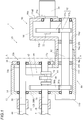
Fig. 1 is a front sectional view of aloom 1 according to an embodiment of the present invention. -
Fig. 2 is a sectional view which is taken along line A-A ofFig. 1 . - Hereinafter, an embodiment (example) of a loom to which the present invention is applied will be described with reference to
Figs. 1 and2 . - In a
loom 1, aframe 10 includes a pair of housing-shaped side frames side frames 12 are connected by a plurality of beam materials. Theloom 1 includes adriving motor 20, and is configured to drive amain shaft 5 of theloom 1 by thedriving motor 20. Thedriving motor 20 is provided on one side frame 12 (hereinafter, referred to as "driving-side frame") side of the pair ofside frames - The driving-
side frame 12 is configured of aframe body 14 that is a main portion, and aframe cover 16 attached to theframe body 14. Specifically, theframe body 14 is formed in a housing shape having a space therein, and a portion (portion corresponding to aswing mechanism 60 or the like described later in a width direction) in a side wall (outer wall portion) 14a, which is an outside in the width direction of theloom 1, is open. Theframe cover 16 is a member formed in a plate shape, and has a size capable of covering an opened portion (opening portion) 14c of theframe body 14. The driving-side frame 12 is configured such that theframe cover 16 is attached to theframe body 14 in a form of covering theopening portion 14c. Therefore, the side wall (outer wall) 12a of the driving-side frame 12 that is the outside in the width direction is configured of theouter wall portion 14a of theframe body 14 and theframe cover 16 that covers theopening portion 14c thereof. Theframe cover 16 is attached to theframe body 14 by using screw members (not illustrated) such as bolts, and theframe cover 16 can be attached or detached to or from theframe body 14. - The loom 1 includes a driving
shaft 30 which is interposed between a drivingmotor 20 and amain shaft 5, is rotationally driven by the drivingmotor 20, and rotationally drives themain shaft 5. The loom 1 includes aswing shaft 50 for driving a lockingshaft 44 to swing in abeating device 40, and aswing mechanism 60 for connecting theswing shaft 50 and the drivingshaft 30. The present example is an example in which a crank mechanism is adopted as theswing mechanism 60. The drivingshaft 30, theswing shaft 50, and theswing mechanism 60 are disposed to be located within a range of theopening portion 14c in the driving-side frame 12 as viewed in the width direction, and are accommodated in the space within the driving-side frame 12. Details of each configuration in such a loom 1 are as follows. - The driving
shaft 30 is formed as a shaft having a dimension (length dimension) in an axial direction, which is larger than a dimension of the driving-side frame 12 in the width direction. However, the drivingshaft 30 is a crank-shaped shaft formed as aneccentric portion 32 of which an intermediate portion is eccentric with respect to portions of both sides (both-side portions). The drivingshaft 30 is rotatably supported by bothside walls side frame 12 via bearings in an orientation in which the axial direction matches with the width direction, and is accommodated in the driving-side frame 12 in such a form. - The support position is located such that the driving
shaft 30 is located below an intermediate portion in theopening portion 14c in theframe body 14 when the driving-side frame 12 is viewed in the width direction. The drivingshaft 30 is supported by theframe cover 16 at one end thereof in one end side. Therefore, the drivingshaft 30 is in a state where a portion including the other end is provided in a form of protruding, on the other end side, from an inner wall (inside wall portion) 14b of theframe body 14 in the width direction. The drivingshaft 30 is supported by the inner wall portion of theframe body 14 at a portion on the driving-side frame 12 side from the protruding portion. Themain shaft 5 is connected to the other end of the drivingshaft 30 by acoupling member 70. - Similar to the driving
shaft 30, theswing shaft 50 is formed as a shaft of which a dimension is larger than the dimension of the driving-side frame 12 in the width direction. Similar to the drivingshaft 30, theswing shaft 50 is supported by the bothside walls side frame 12 via bearings in the orientation parallel to the drivingshaft 30, and is accommodated in the driving-side frame 12. Similar to the drivingshaft 30, the support position is a position within the range of theopening portion 14c in theframe body 14 when the driving-side frame 12 is viewed in the width direction, and is a position above the drivingshaft 30. Theswing shaft 50 is also supported by theframe cover 16 at one end thereof, a portion including the other end is provided so as to protrude from theinner wall portion 14b of theframe body 14, and is supported by theinner wall portion 14b of theframe body 14 at the other end side thereof. A lockingshaft 44 that supports thereed 42 is connected to the other end of theswing shaft 50 by acoupling member 72. - As described above, the
swing mechanism 60 is the crank mechanism and includes aswing arm 62 which is provided so as not to rotate relative to theswing shaft 50, and aconnection lever 64 which is a link for connecting theswing arm 62 and theeccentric portion 32 of the drivingshaft 30. In the illustrated example, theswing shaft 50 and theswing arm 62 are integrally formed. Theconnection lever 64 is relatively rotatably connected to theswing arm 62 and the driving shaft 30 (eccentric portion 32). In theswing mechanism 60, the drivingshaft 30 is rotationally driven and theeccentric portion 32 is rotationally moved at a position eccentric from a shaft center of both side portions, and thereby the swing arm 62 (swing shaft 50) connected to theeccentric portion 32 via theconnection lever 64 is driven to swing. Therefore, in that configuration, a part of the drivingshaft 30 also functions as theswing mechanism 60. As described above, theswing shaft 50 is driven to swing, and thereby the lockingshaft 44 connected to theswing shaft 50 and thereed 42 supported by the lockingshaft 44 move to swing, and the beating operation is performed. - In the loom 1 described above, the
loom 1 includes a driving-force transmission mechanism 80 that connects the drivingshaft 30 and the drivingmotor 20. Therefore, the drivingshaft 30 connected to themain shaft 5 is rotationally driven by the drivingmotor 20. In the present invention, the driving-force transmission mechanism 80 is configured to include a driving-force transmission shaft 82 connected to the drivingmotor 20 and atransmission mechanism 84 connecting the driving-force transmission shaft 82 and the drivingshaft 30. The present example is an example in which thetransmission mechanism 84 is a gear train and the gear train is accommodated in the driving-side frame 12. Details of the driving-force transmission mechanism 80 of the present example are as follows. - The driving-
force transmission shaft 82 is formed as a shaft of which a dimension (length dimension) in the axial direction is larger than the dimension of the driving-side frame 12 in the width direction and is larger than the length dimension of the drivingshaft 30. The driving-force transmission shaft 82 is provided to be supported by theinner wall 12b of the driving-side frame 12 via a bearing on one end side thereof in the orientation parallel to the drivingshaft 30, and penetrate theouter wall portion 14a (outer wall 12a of the driving-side frame 12) of theframe body 14, and the other end thereof is located on the outside of theouter wall portion 14a. Therefore, the driving-force transmission shaft 82 is in a state where a portion between the portion supported by the bearing and theouter wall portion 14a is accommodated within the driving-side frame 12. However, as described above, although the driving-force transmission shaft 82 is supported by theinner wall 12b on the one end side, the driving-force transmission shaft 82 also protrudes from theinner wall 12b so that the one end is located on the outside of theinner wall 12b. The driving-force transmission shaft 82 provided as described above is connected to the drivingshaft 30 by thetransmission mechanism 84 within the driving-side frame 12. - The support position of the driving-
force transmission shaft 82 is a position outside the range of theopening portion 14c in theframe body 14, and is a position separated downward from the drivingshaft 30. In theouter wall portion 14a of theframe body 14, a throughhole 14d is formed at a position corresponding to the support position to allow the driving-force transmission shaft 82 to penetrate as described above. - In the present example, the
transmission mechanism 84 is configured as a gear train including two gears accommodated within the driving-side frame 12. Specifically, thetransmission mechanism 84 is configured of adriving gear 84a attached so as not to rotate relative to the driving-force transmission shaft 82, and a drivengear 84b that meshes with thedriving gear 84a and is attached so as not to rotate relative to the drivingshaft 30. However, the position where thedriving gear 84a and the drivengear 84b are attached to each shaft is a position on theinner wall 12b side of the driving-side frame 12 in the width direction from the connection position between the driving shaft 30 (eccentric portion 32) and the swing mechanism 60 (connection lever 64). That is, in the present example, the driving-force transmission shaft 82 and the drivingshaft 30 are connected at a position on theinner wall 12b side of the driving-side frame 12 in the width direction from the connection position between the drivingshaft 30 and theswing mechanism 60. - The driving-
force transmission shaft 82 is adriving mechanism 90 for rotationally driving the driving-force transmission shaft 82 on the other end side, and is connected to thedriving mechanism 90 including the drivingmotor 20. In addition to the drivingmotor 20, thedriving mechanism 90 includes adriving gear train 92 that connects theoutput shaft 22 of the drivingmotor 20 and the driving-force transmission shaft 82. Thedriving mechanism 90 is configured to have a housing-shapeddriving box 94 as a base, the drivingmotor 20 is attached to the outer surface of thedriving box 94, and thedriving gear train 92 is accommodated within thedriving box 94. - In the
driving box 94, the drivingmotor 20 is attached to an outer surface 94a1 of oneside wall 94a of the pair ofside walls side walls outer wall 12a of the driving-side frame 12. Thedriving box 94 is provided to overlap the driving-side frame 12 in the back and forth direction of theloom 1. As described above, since the driving-force transmission shaft 82 protruding from the driving-side frame 12 is connected to thedriving gear train 92 accommodated within thedriving box 94, the driving-force transmission shaft 82 penetrates theother side wall 94b of the pair ofside walls driving box 94, and the portion of the other end side is located within the driving box 94 (accommodated in the driving box 94). Therefore, a throughhole 94d that allows the penetration of the driving-force transmission shaft 82 is formed on theother side wall 94b in thedriving box 94. - As described above, the driving-
force transmission shaft 82 protruding from the driving-side frame 12 is supported by oneside wall 94a in thedriving box 94 via a bearing at the other end. However, thedriving box 94 is provided such that theother side wall 94b through which the driving-force transmission shaft 82 penetrates is separated from the driving-side frame 12. - The driving
motor 20 is attached to thedriving box 94 by bolts or the like (not illustrated) such that theoutput shaft 22 is oriented toward the driving-side frame 12 side at a position separated upward with respect to the driving-force transmission shaft 82 supported as described above. A throughhole 94c is formed on oneside wall 94a in thedriving box 94 to which the drivingmotor 20 is attached to allow theoutput shaft 22 of the drivingmotor 20 to penetrate at the attachment position. Therefore, as described above, in a state where the drivingmotor 20 is attached to thedriving box 94, theoutput shaft 22 extends within thedriving box 94 in the width direction and exists to be parallel to the driving-force transmission shaft 82. Theoutput shaft 22 is connected to a portion of the driving-force transmission shaft 82 on the portion of the other end side of via thedriving gear train 92 within thedriving box 94. - Similar to the
gear train 84 connecting the drivingshaft 30 and the driving-force transmission shaft 82, thedriving gear train 92 is configured of two gears. Specifically, thedriving gear train 92 is configured of adriving gear 92a that is attached so as not to rotate relative to theoutput shaft 22 of the drivingmotor 20, and a drivengear 92b that meshes with thedriving gear 92a and is attached so as not to rotate relative to the driving-force transmission shaft 82. - The loom 1 includes a braking device (for example, an electromagnetic brake) 110 for applying a brake to the
main shaft 5 connected to the drivingshaft 30. Thebraking device 110 is provided so as to be connected to the driving-force transmission shaft 82 at a position inside from the driving-side frame 12 in the width direction. Therefore, the driving-force transmission shaft 82 is provided such that one end thereof protrudes from theinner wall 12b of the driving-side frame 12 for connection with thebraking device 110. Thebraking device 110 is attached to theinner wall 12b of the driving-side frame 12 and is connected to one end of the protruding driving-force transmission shaft 82. According to such a configuration, when the loom 1 (main shaft 5) is braked, the driving-force transmission shaft 82 is braked by thebraking device 110, so that the brake is applied to the drivingshaft 30 connected viatransmission mechanism 84 as described above. As a result, the rotation of themain shaft 5 which is connected to the drivingshaft 30 is stopped. - In the illustrated example, the
frame body 14 has a protrudingportion 14e formed to protrude from theouter wall portion 14a toward thedriving box 94 side around the throughhole 14d in theouter wall portion 14a. On the other hand, thedriving box 94 also has a protrudingportion 94e formed to protrude from theother side wall 94b toward the driving-side frame 12 side around the throughhole 94d in theother side wall 94b. Theframe body 14 and thedriving box 94 are connected such that the both protrudingportions portions portions force transmission shaft 82. - According to the loom 1 of the present example configured as described above, the driving-
force transmission shaft 82 in the driving-force transmission mechanism 80, which transmits the rotation of the driving motor 20 (output shaft 22) to themain shaft 5, and is connected to themain shaft 5 and rotationally driven by the drivingmotor 20, is configured such that the one end side portion is accommodated in the driving-side frame 12 and connected to the drivingshaft 30 within the driving-side frame 12. - The connection position between the driving-
force transmission shaft 82 and the drivingshaft 30 is the position on theinner wall 12b side of the driving-side frame 12 which is themain shaft 5 side (connection position side between the drivingshaft 30 and the main shaft 5) with respect to the connection position between the drivingshaft 30 and theswing mechanism 60 in the width direction. Therefore, on the drivingshaft 30, the connection position with the driving-force transmission mechanism 80 (transmission mechanism 84) becomes a restraint point of the drivingshaft 30. In the connection position with theswing mechanism 60 and the connection position with themain shaft 5, one (swing mechanism 60 side) is located on one shaft end side (one end side) with respect to the restraint point, and the other (main shaft 5 side) is located on the other shaft end side (the other end side). Therefore, the rotational resistance acting on the drivingshaft 30 at the connection position with theswing mechanism 60 and the connection position with themain shaft 5 acts at one place on each of the both end sides (one end side and the other end side) of the shaft with respect to the restraint point. - According to the loom 1 configured as described above, each amount of twist at the connection portion with the
swing mechanism 60 and the connection portion with themain shaft 5 in the drivingshaft 30 is reduced compared with that of the configuration of the related art in which all the rotational resistance acts on one end side of the shaft with respect to the restraint point. As a result, the phase deviation occurred due to the twist of the drivingshaft 30 in the device connected to the drivingshaft 30 becomes small compared with that of the configuration of the related art. - In the
loom 1, abraking device 110 is provided to apply a brake to the driving-force transmission shaft 82 connected to the drivingshaft 30. Therefore, according to the configuration, when themain shaft 5 is braked, the load (inertia force) applied to the connection position between themain shaft 5 and theswing mechanism 60 in the drivingshaft 30 acts at one place on each of the both end sides of the shaft with respect to the restraint point similar to the rotational resistance described above. Therefore, the amount of twist of the drivingshaft 30 due to the load when themain shaft 5 is braked becomes small similar to the amount of twist due to the rotational resistance described above, and damage of the bearing due to the twist of the drivingshaft 30 during braking can be prevented as much as possible. - In the above, one embodiment (hereinafter, referred to as "the above example") of the loom to which the present invention is applied is described. However, the present invention is not limited to the configuration described in the above example, and can be implemented in other embodiments (modified examples) as described below.
- (1) Regarding the transmission mechanism that connects the driving shaft and the driving-force transmission shaft, the transmission mechanism is not limited to the gear train configured of two gears of the
driving gear 84a and the drivengear 84b which are accommodated within the driving-side frame 12 as in the above example. For example, the transmission mechanism may be one that is also configured of the same gear train, or may be a gear train that is configured of three or more gears. The transmission mechanism is not limited to one configured of the gear train, and may be configured to connect a pulley attached to the driving shaft and a pulley attached to the driving-force transmission shaft with a timing belt. - (2) Regarding the position where the driving shaft and the driving-force transmission shaft are connected by the transmission mechanism, the connection position (restraint point) is not limited to the position within the driving-side frame as in the above example. For example, after forming the driving-force transmission shaft as an shaft so as to protrude to the main shaft side from the inner wall of the driving-side frame, the driving shaft and the driving-force transmission shaft may be connected at a position (position on the main shaft side in the width direction from the inner wall of the driving-side frame) other than driving-side frame.
- (3) Regarding the position where the braking device is provided, in the above example, the
braking device 110 is provided inside the driving-side frame 12 in the width direction in a form of connecting to the driving-force transmission shaft 82. However, in the present invention, the position where the braking device is provided is not limited to the inside and may also be outside the driving-side frame even in a case of being connected to the driving-force transmission shaft. In that case, the braking device may be attached to the outer wall of the driving-side frame or attached to the side wall of the driving box.
The present invention is not limited to the configuration in which the braking device in the form of connecting to the driving-force transmission shaft is provided, and the braking device may be provided in a form of connecting to the driving shaft. For the disposition of the braking device, the driving shaft and the driving-force transmission shaft may be separate shafts (brake shaft), the brake shaft connected to the driving shaft or the driving-force transmission shaft via a gear train or the like may be provided within the side frame, and a braking device may be provided to be connected to the brake shaft. - (4) Regarding the swing mechanism, the above example is an example of the present invention applied to the loom in which the crank mechanism is adopted as the
swing mechanism 60. In the above example, theswing arm 62 in theswing mechanism 60 is integrally formed with theswing shaft 50. However, even in the crank mechanism as in the above example, the swing mechanism may be configured such that the swing arm and the swing shaft are formed as separate members, and both are connected so as not to rotate relative to each other. The swing mechanism is not limited to the crank mechanism as in the above example, and may be a cam mechanism. In that case, the shaft to which the cam is attached becomes the driving shaft in the present invention. - Further, the present invention is not limited to the above-described embodiments, and various modifications can be made without departing from the gist of the present invention.
Claims (4)
- A loom (1) comprising:a driving shaft (30) to which a main shaft (5) of the loom (1) is connected and to which a swing shaft (50) for driving a reed (42) to swing is connected via a swing mechanism (60);a driving motor (20) to which the driving shaft (30) is connected via a driving-force transmission mechanism (80) to rotationally drive the driving shaft (30);a braking device (110) that applies a brake to the main shaft (5) connected to the driving shaft (30); anda housing-shaped side frame (12) that accommodates the driving shaft (30) and the swing shaft (50) in an orientation in which each axial direction of the driving shaft (30) and the swing shaft (50) matches with a width direction,wherein the driving-force transmission mechanism (80) includes a driving-force transmission shaft (82) that is provided so as to protrude from a side wall (12b) of the side frame (12) while extending parallel to the driving shaft (30) within a space of the side frame (12) and connected to the driving motor (20), and a transmission mechanism (84) that connects the driving-force transmission shaft (82) and the driving shaft (30), andthe transmission mechanism (84) connects the driving-force transmission shaft (82) and the driving shaft (30) at a position on a main shaft (5) side in the width direction from a connection position between the driving shaft (30) and the swing mechanism (60).
- The loom (1) according to claim 1, wherein the transmission mechanism (84) is a gear train including a driving gear (84a) attached to the driving-force transmission shaft (82) and a driven gear (84b) attached to the driving shaft (30).
- The loom (1) according to claim 1 or 2, wherein the braking device (110) is connected to the driving-force transmission shaft (82) to apply a brake to the driving shaft (30) via the driving-force transmission shaft (82).
- The loom (1) according to claim 2, wherein the driving shaft (30) is a crank-shaped shaft formed as an eccentric portion (32) of which an intermediate portion is eccentric with respect to both side portions, and the swing mechanism (60) is connected to the eccentric portion (32).
Applications Claiming Priority (1)
| Application Number | Priority Date | Filing Date | Title |
|---|---|---|---|
| JP2020097692A JP7401397B2 (en) | 2020-06-04 | 2020-06-04 | loom |
Publications (2)
| Publication Number | Publication Date |
|---|---|
| EP3919662A1 true EP3919662A1 (en) | 2021-12-08 |
| EP3919662B1 EP3919662B1 (en) | 2024-12-25 |
Family
ID=76283538
Family Applications (1)
| Application Number | Title | Priority Date | Filing Date |
|---|---|---|---|
| EP21176616.7A Active EP3919662B1 (en) | 2020-06-04 | 2021-05-28 | Loom |
Country Status (6)
| Country | Link |
|---|---|
| US (1) | US11732389B2 (en) |
| EP (1) | EP3919662B1 (en) |
| JP (1) | JP7401397B2 (en) |
| KR (1) | KR20210150975A (en) |
| CN (2) | CN214882087U (en) |
| TW (1) | TWI902807B (en) |
Families Citing this family (5)
| Publication number | Priority date | Publication date | Assignee | Title |
|---|---|---|---|---|
| JP7401397B2 (en) * | 2020-06-04 | 2023-12-19 | 津田駒工業株式会社 | loom |
| JP7384747B2 (en) * | 2020-06-04 | 2023-11-21 | 津田駒工業株式会社 | loom |
| JP7477372B2 (en) * | 2020-06-04 | 2024-05-01 | 津田駒工業株式会社 | loom |
| JP7491819B2 (en) * | 2020-11-24 | 2024-05-28 | 津田駒工業株式会社 | Crank drive for loom |
| JP2024075012A (en) * | 2022-11-22 | 2024-06-03 | 津田駒工業株式会社 | Warp beam receiving mechanism for a loom |
Citations (4)
| Publication number | Priority date | Publication date | Assignee | Title |
|---|---|---|---|---|
| JPH05156551A (en) * | 1991-05-23 | 1993-06-22 | Picanol Nv | Method and apparatus for slow motion driving for weaving machine |
| EP1245707A1 (en) * | 2001-03-29 | 2002-10-02 | Promatech S.p.A. | Multi-position front clutch having a blocking device of the movable element in a control drive of a loom |
| JP2004107838A (en) | 2002-09-20 | 2004-04-08 | Tsudakoma Corp | Loom frame and method of switching beating method in loom |
| EP1600542A2 (en) * | 2004-05-25 | 2005-11-30 | Smit S.p.A. - Unipersonale | Control device for textile weaving looms |
Family Cites Families (54)
| Publication number | Priority date | Publication date | Assignee | Title |
|---|---|---|---|---|
| US983550A (en) * | 1907-08-06 | 1911-02-07 | Us Automatic Loom Attachment Company | Loom. |
| US2561416A (en) * | 1946-02-26 | 1951-07-24 | Bond Worth & Sons Ltd T | Selvage forming mechanism |
| US2522629A (en) * | 1947-05-10 | 1950-09-19 | Kellogg M W Co | Warp stop mechanism |
| US2582761A (en) * | 1950-07-31 | 1952-01-15 | Lansdowne Steel & Iron Company | Actuating mechanism for picking sticks |
| US2889855A (en) * | 1954-06-23 | 1959-06-09 | Singer Mfg Co | Loom driving mechanism |
| US2791242A (en) * | 1954-12-14 | 1957-05-07 | Emerson P Cashion | Automatic filling rake |
| BE671649A (en) * | 1964-11-02 | 1966-02-14 | ||
| US3441058A (en) * | 1965-11-05 | 1969-04-29 | Friedrich Wilhelm Bassing | Loom crankshaft arrangement |
| US3400423A (en) * | 1966-08-23 | 1968-09-10 | Parks Cramer Co | Air outlet suspension system for textile traveling cleaners |
| US3460660A (en) * | 1967-07-07 | 1969-08-12 | Pyle National Co | Loom beam storage and dispensing device |
| SE307925B (en) | 1968-09-02 | 1969-01-20 | Aelmhults Bruk Ab | |
| JPS5953380B2 (en) * | 1976-12-10 | 1984-12-25 | 津田駒工業株式会社 | Weaving method and equipment |
| JPS6036621Y2 (en) * | 1979-08-02 | 1985-10-30 | 株式会社豊田自動織機製作所 | Drive support device for cross rollers for indirect winding in looms |
| JPS5691045A (en) * | 1979-12-18 | 1981-07-23 | Takemura Toshihiro | Apparatus for converting power loom to hand weaving type |
| FR2478682A1 (en) * | 1980-03-20 | 1981-09-25 | Staubli Sa Ets | IMPROVEMENTS IN RATIO OF THE ROTARY TYPE FOR WEAVING |
| WO1983002466A1 (en) * | 1982-01-16 | 1983-07-21 | Griffith, John, Dalton | Yarn holding device |
| JPH0733615B2 (en) * | 1986-01-22 | 1995-04-12 | 株式会社豊田自動織機製作所 | Weft processing method for shuttleless loom |
| US4850399A (en) * | 1987-06-27 | 1989-07-25 | Lindauer Dorner Gesellschaft M.B.H. | Weaving loom with pneumatic weft thread injection |
| EP0344100B1 (en) * | 1988-05-20 | 1992-07-08 | GebràDer Sulzer Aktiengesellschaft | Electro-magnetical device for looms |
| BE1002764A6 (en) * | 1989-01-23 | 1991-05-28 | Wiele Michel Van De Nv | CONTROL MECHANISM FOR SELECTING IMPACT ON WIRES rapier weaving machines. |
| JPH06212537A (en) * | 1993-01-19 | 1994-08-02 | Yoshida Kogyo Kk <Ykk> | Loom |
| US5259420A (en) * | 1993-02-10 | 1993-11-09 | Foster Harry L | Upper warp beam supporting assembly and method |
| DE4306612C1 (en) * | 1993-03-03 | 1994-01-13 | Dornier Gmbh Lindauer | Cam drive transmission - composed of a four linkage system to set sley shaft for weaving plain or towelling fabrics in a shuttleless loom |
| JP3424367B2 (en) * | 1994-04-06 | 2003-07-07 | 株式会社豊田自動織機 | Shedding control device in loom |
| JPH0978405A (en) | 1995-09-08 | 1997-03-25 | Nissan Tecsys Kk | Device for preventing weaving bar in loom |
| JPH10102357A (en) * | 1996-09-26 | 1998-04-21 | Toyota Autom Loom Works Ltd | Beating controlling method in loom, and apparatus therefor |
| BE1010849A3 (en) * | 1997-01-14 | 1999-02-02 | Picanol Nv | DRIVE for a weaving machine. |
| JP2003170699A (en) * | 2001-12-07 | 2003-06-17 | Kotobuki:Kk | Clip mounting structure |
| TW552329B (en) * | 2002-09-19 | 2003-09-11 | Chi-Tzeng Jang | Adjustable weft-knitting transmission device for a loom |
| EP1452265B1 (en) * | 2003-02-26 | 2005-04-20 | FELSOMAT GmbH & Co. KG | Base platform for a manipulation device and manipulation device |
| JP4383964B2 (en) * | 2004-05-31 | 2009-12-16 | 津田駒工業株式会社 | Loom hammering device |
| BE1016108A6 (en) * | 2004-07-05 | 2006-03-07 | Picanol Nv | |
| JP4595408B2 (en) * | 2004-07-08 | 2010-12-08 | パナソニック株式会社 | Compressor |
| JP2007107147A (en) * | 2005-10-14 | 2007-04-26 | Tsudakoma Corp | Weaving length measuring storage device of loom |
| ITBS20060066A1 (en) * | 2006-03-23 | 2007-09-24 | Santoni & C Spa | COMMAND DEVICE FOR OSCILLATING BARS DOOR THROUGH BARS FOR LINEAR TEXTILE MACHINES |
| TW200743688A (en) * | 2006-05-16 | 2007-12-01 | Lin Zhen Hui | Beat-up stroke transmission device of knitting machine |
| JP2007332477A (en) * | 2006-06-13 | 2007-12-27 | Tsudakoma Corp | Loom drive unit |
| US7520788B1 (en) * | 2007-09-28 | 2009-04-21 | Gustavo Gonzalez | Reciprocating oar with propulsion reversing system |
| CN101922076B (en) | 2009-06-12 | 2012-08-15 | 赵斯伟 | Shedding device of weaving machine |
| CN101914831B (en) * | 2010-08-10 | 2012-03-28 | 广东丰凯机械股份有限公司 | Loom transmission mechanism |
| CN202107883U (en) * | 2011-06-14 | 2012-01-11 | 徐石渊 | Improvement of Separate Transmission Structure of Straight Cylinder Interlock Sewing Machine |
| CN103015011A (en) * | 2012-12-25 | 2013-04-03 | 浙江建达电器有限公司 | Driving device of rapier loom |
| JP6377969B2 (en) * | 2014-06-11 | 2018-08-22 | 津田駒工業株式会社 | Loom hammering device |
| CN105755651B (en) * | 2016-04-26 | 2017-07-07 | 江苏友诚数控科技有限公司 | A kind of wefting insertion beating-up mechanism of loom |
| US20190145658A1 (en) * | 2017-11-16 | 2019-05-16 | Akurate Dynamics, Llc | In-line electric heater for plural component materials |
| CN209508527U (en) * | 2018-12-13 | 2019-10-18 | 浙江泰坦股份有限公司 | A kind of loom drive mechanism |
| NL2022751B1 (en) * | 2019-03-15 | 2020-11-26 | Top Vision Group | FRAME PROTECTION DEVICE AND METHOD |
| JP7517859B2 (en) * | 2020-04-22 | 2024-07-17 | 津田駒工業株式会社 | Frame structure of the loom |
| JP7384747B2 (en) * | 2020-06-04 | 2023-11-21 | 津田駒工業株式会社 | loom |
| JP7401397B2 (en) * | 2020-06-04 | 2023-12-19 | 津田駒工業株式会社 | loom |
| JP7477372B2 (en) * | 2020-06-04 | 2024-05-01 | 津田駒工業株式会社 | loom |
| JP7453115B2 (en) * | 2020-09-30 | 2024-03-19 | 津田駒工業株式会社 | loom |
| JP7509639B2 (en) * | 2020-09-30 | 2024-07-02 | 津田駒工業株式会社 | Loom frame |
| FR3118070B1 (en) * | 2020-12-21 | 2022-12-23 | Staubli Lyon | SHEDDING MECHANISM AND JACQUARD TYPE Loom |
-
2020
- 2020-06-04 JP JP2020097692A patent/JP7401397B2/en active Active
-
2021
- 2021-05-24 KR KR1020210066028A patent/KR20210150975A/en active Pending
- 2021-05-28 US US17/333,822 patent/US11732389B2/en active Active
- 2021-05-28 EP EP21176616.7A patent/EP3919662B1/en active Active
- 2021-05-28 TW TW110119327A patent/TWI902807B/en active
- 2021-05-31 CN CN202121185285.2U patent/CN214882087U/en active Active
- 2021-05-31 CN CN202110597491.2A patent/CN113755995A/en active Pending
Patent Citations (4)
| Publication number | Priority date | Publication date | Assignee | Title |
|---|---|---|---|---|
| JPH05156551A (en) * | 1991-05-23 | 1993-06-22 | Picanol Nv | Method and apparatus for slow motion driving for weaving machine |
| EP1245707A1 (en) * | 2001-03-29 | 2002-10-02 | Promatech S.p.A. | Multi-position front clutch having a blocking device of the movable element in a control drive of a loom |
| JP2004107838A (en) | 2002-09-20 | 2004-04-08 | Tsudakoma Corp | Loom frame and method of switching beating method in loom |
| EP1600542A2 (en) * | 2004-05-25 | 2005-11-30 | Smit S.p.A. - Unipersonale | Control device for textile weaving looms |
Also Published As
| Publication number | Publication date |
|---|---|
| KR20210150975A (en) | 2021-12-13 |
| US20210381138A1 (en) | 2021-12-09 |
| EP3919662B1 (en) | 2024-12-25 |
| US11732389B2 (en) | 2023-08-22 |
| TW202146725A (en) | 2021-12-16 |
| TWI902807B (en) | 2025-11-01 |
| JP7401397B2 (en) | 2023-12-19 |
| CN214882087U (en) | 2021-11-26 |
| JP2021188215A (en) | 2021-12-13 |
| CN113755995A (en) | 2021-12-07 |
Similar Documents
| Publication | Publication Date | Title |
|---|---|---|
| US11732389B2 (en) | Loom | |
| EP3919661B1 (en) | Loom | |
| EP3919660B1 (en) | Loom | |
| JPWO2007080988A1 (en) | Joint mechanism | |
| JP7424816B2 (en) | robot joint structure | |
| US11993872B2 (en) | Loom | |
| CN101858009B (en) | Driving mechanism for weaving-related device weaving machine | |
| WO2015033945A1 (en) | Rice planting machine | |
| JP2002284430A (en) | Cut off of corrugating machine | |
| CN101634079B (en) | Planetary gear type selvage machine of loom | |
| JP2007022215A (en) | Electrically operated door mirror device | |
| JP6124741B2 (en) | Rice transplanter | |
| JP2002173216A (en) | Driving device of chain conveyor | |
| JP2020150732A (en) | Motor actuator | |
| JP2001132800A (en) | Door drive mechanism | |
| PL188114B1 (en) | Shaking down machine with an interial head |
Legal Events
| Date | Code | Title | Description |
|---|---|---|---|
| PUAI | Public reference made under article 153(3) epc to a published international application that has entered the european phase |
Free format text: ORIGINAL CODE: 0009012 |
|
| STAA | Information on the status of an ep patent application or granted ep patent |
Free format text: STATUS: THE APPLICATION HAS BEEN PUBLISHED |
|
| AK | Designated contracting states |
Kind code of ref document: A1 Designated state(s): AL AT BE BG CH CY CZ DE DK EE ES FI FR GB GR HR HU IE IS IT LI LT LU LV MC MK MT NL NO PL PT RO RS SE SI SK SM TR |
|
| B565 | Issuance of search results under rule 164(2) epc |
Effective date: 20211021 |
|
| STAA | Information on the status of an ep patent application or granted ep patent |
Free format text: STATUS: REQUEST FOR EXAMINATION WAS MADE |
|
| 17P | Request for examination filed |
Effective date: 20220602 |
|
| RBV | Designated contracting states (corrected) |
Designated state(s): AL AT BE BG CH CY CZ DE DK EE ES FI FR GB GR HR HU IE IS IT LI LT LU LV MC MK MT NL NO PL PT RO RS SE SI SK SM TR |
|
| GRAP | Despatch of communication of intention to grant a patent |
Free format text: ORIGINAL CODE: EPIDOSNIGR1 |
|
| STAA | Information on the status of an ep patent application or granted ep patent |
Free format text: STATUS: GRANT OF PATENT IS INTENDED |
|
| INTG | Intention to grant announced |
Effective date: 20240327 |
|
| GRAJ | Information related to disapproval of communication of intention to grant by the applicant or resumption of examination proceedings by the epo deleted |
Free format text: ORIGINAL CODE: EPIDOSDIGR1 |
|
| STAA | Information on the status of an ep patent application or granted ep patent |
Free format text: STATUS: REQUEST FOR EXAMINATION WAS MADE |
|
| GRAP | Despatch of communication of intention to grant a patent |
Free format text: ORIGINAL CODE: EPIDOSNIGR1 |
|
| STAA | Information on the status of an ep patent application or granted ep patent |
Free format text: STATUS: GRANT OF PATENT IS INTENDED |
|
| INTC | Intention to grant announced (deleted) | ||
| INTG | Intention to grant announced |
Effective date: 20240726 |
|
| GRAS | Grant fee paid |
Free format text: ORIGINAL CODE: EPIDOSNIGR3 |
|
| GRAA | (expected) grant |
Free format text: ORIGINAL CODE: 0009210 |
|
| STAA | Information on the status of an ep patent application or granted ep patent |
Free format text: STATUS: THE PATENT HAS BEEN GRANTED |
|
| AK | Designated contracting states |
Kind code of ref document: B1 Designated state(s): AL AT BE BG CH CY CZ DE DK EE ES FI FR GB GR HR HU IE IS IT LI LT LU LV MC MK MT NL NO PL PT RO RS SE SI SK SM TR |
|
| REG | Reference to a national code |
Ref country code: GB Ref legal event code: FG4D |
|
| REG | Reference to a national code |
Ref country code: CH Ref legal event code: EP |
|
| REG | Reference to a national code |
Ref country code: DE Ref legal event code: R096 Ref document number: 602021023785 Country of ref document: DE |
|
| REG | Reference to a national code |
Ref country code: IE Ref legal event code: FG4D |
|
| REG | Reference to a national code |
Ref country code: LT Ref legal event code: MG9D |
|
| PG25 | Lapsed in a contracting state [announced via postgrant information from national office to epo] |
Ref country code: HR Free format text: LAPSE BECAUSE OF FAILURE TO SUBMIT A TRANSLATION OF THE DESCRIPTION OR TO PAY THE FEE WITHIN THE PRESCRIBED TIME-LIMIT Effective date: 20241225 |
|
| PG25 | Lapsed in a contracting state [announced via postgrant information from national office to epo] |
Ref country code: FI Free format text: LAPSE BECAUSE OF FAILURE TO SUBMIT A TRANSLATION OF THE DESCRIPTION OR TO PAY THE FEE WITHIN THE PRESCRIBED TIME-LIMIT Effective date: 20241225 |
|
| PG25 | Lapsed in a contracting state [announced via postgrant information from national office to epo] |
Ref country code: BG Free format text: LAPSE BECAUSE OF FAILURE TO SUBMIT A TRANSLATION OF THE DESCRIPTION OR TO PAY THE FEE WITHIN THE PRESCRIBED TIME-LIMIT Effective date: 20241225 |
|
| PG25 | Lapsed in a contracting state [announced via postgrant information from national office to epo] |
Ref country code: NO Free format text: LAPSE BECAUSE OF FAILURE TO SUBMIT A TRANSLATION OF THE DESCRIPTION OR TO PAY THE FEE WITHIN THE PRESCRIBED TIME-LIMIT Effective date: 20250325 |
|
| PG25 | Lapsed in a contracting state [announced via postgrant information from national office to epo] |
Ref country code: LV Free format text: LAPSE BECAUSE OF FAILURE TO SUBMIT A TRANSLATION OF THE DESCRIPTION OR TO PAY THE FEE WITHIN THE PRESCRIBED TIME-LIMIT Effective date: 20241225 Ref country code: GR Free format text: LAPSE BECAUSE OF FAILURE TO SUBMIT A TRANSLATION OF THE DESCRIPTION OR TO PAY THE FEE WITHIN THE PRESCRIBED TIME-LIMIT Effective date: 20250326 |
|
| PG25 | Lapsed in a contracting state [announced via postgrant information from national office to epo] |
Ref country code: RS Free format text: LAPSE BECAUSE OF FAILURE TO SUBMIT A TRANSLATION OF THE DESCRIPTION OR TO PAY THE FEE WITHIN THE PRESCRIBED TIME-LIMIT Effective date: 20250325 |
|
| REG | Reference to a national code |
Ref country code: NL Ref legal event code: MP Effective date: 20241225 |
|
| PG25 | Lapsed in a contracting state [announced via postgrant information from national office to epo] |
Ref country code: NL Free format text: LAPSE BECAUSE OF FAILURE TO SUBMIT A TRANSLATION OF THE DESCRIPTION OR TO PAY THE FEE WITHIN THE PRESCRIBED TIME-LIMIT Effective date: 20241225 |
|
| REG | Reference to a national code |
Ref country code: AT Ref legal event code: MK05 Ref document number: 1754223 Country of ref document: AT Kind code of ref document: T Effective date: 20241225 |
|
| PG25 | Lapsed in a contracting state [announced via postgrant information from national office to epo] |
Ref country code: SM Free format text: LAPSE BECAUSE OF FAILURE TO SUBMIT A TRANSLATION OF THE DESCRIPTION OR TO PAY THE FEE WITHIN THE PRESCRIBED TIME-LIMIT Effective date: 20241225 |
|
| PG25 | Lapsed in a contracting state [announced via postgrant information from national office to epo] |
Ref country code: PL Free format text: LAPSE BECAUSE OF FAILURE TO SUBMIT A TRANSLATION OF THE DESCRIPTION OR TO PAY THE FEE WITHIN THE PRESCRIBED TIME-LIMIT Effective date: 20241225 |
|
| PGFP | Annual fee paid to national office [announced via postgrant information from national office to epo] |
Ref country code: DE Payment date: 20250402 Year of fee payment: 5 |
|
| PG25 | Lapsed in a contracting state [announced via postgrant information from national office to epo] |
Ref country code: ES Free format text: LAPSE BECAUSE OF FAILURE TO SUBMIT A TRANSLATION OF THE DESCRIPTION OR TO PAY THE FEE WITHIN THE PRESCRIBED TIME-LIMIT Effective date: 20241225 |
|
| PG25 | Lapsed in a contracting state [announced via postgrant information from national office to epo] |
Ref country code: IS Free format text: LAPSE BECAUSE OF FAILURE TO SUBMIT A TRANSLATION OF THE DESCRIPTION OR TO PAY THE FEE WITHIN THE PRESCRIBED TIME-LIMIT Effective date: 20250425 |
|
| PGFP | Annual fee paid to national office [announced via postgrant information from national office to epo] |
Ref country code: BE Payment date: 20250410 Year of fee payment: 5 Ref country code: IT Payment date: 20250422 Year of fee payment: 5 |
|
| PG25 | Lapsed in a contracting state [announced via postgrant information from national office to epo] |
Ref country code: PT Free format text: LAPSE BECAUSE OF FAILURE TO SUBMIT A TRANSLATION OF THE DESCRIPTION OR TO PAY THE FEE WITHIN THE PRESCRIBED TIME-LIMIT Effective date: 20250428 |
|
| PG25 | Lapsed in a contracting state [announced via postgrant information from national office to epo] |
Ref country code: EE Free format text: LAPSE BECAUSE OF FAILURE TO SUBMIT A TRANSLATION OF THE DESCRIPTION OR TO PAY THE FEE WITHIN THE PRESCRIBED TIME-LIMIT Effective date: 20241225 |
|
| PG25 | Lapsed in a contracting state [announced via postgrant information from national office to epo] |
Ref country code: RO Free format text: LAPSE BECAUSE OF FAILURE TO SUBMIT A TRANSLATION OF THE DESCRIPTION OR TO PAY THE FEE WITHIN THE PRESCRIBED TIME-LIMIT Effective date: 20241225 Ref country code: AT Free format text: LAPSE BECAUSE OF FAILURE TO SUBMIT A TRANSLATION OF THE DESCRIPTION OR TO PAY THE FEE WITHIN THE PRESCRIBED TIME-LIMIT Effective date: 20241225 |
|
| PG25 | Lapsed in a contracting state [announced via postgrant information from national office to epo] |
Ref country code: SK Free format text: LAPSE BECAUSE OF FAILURE TO SUBMIT A TRANSLATION OF THE DESCRIPTION OR TO PAY THE FEE WITHIN THE PRESCRIBED TIME-LIMIT Effective date: 20241225 |
|
| PG25 | Lapsed in a contracting state [announced via postgrant information from national office to epo] |
Ref country code: CZ Free format text: LAPSE BECAUSE OF FAILURE TO SUBMIT A TRANSLATION OF THE DESCRIPTION OR TO PAY THE FEE WITHIN THE PRESCRIBED TIME-LIMIT Effective date: 20241225 |
|
| PG25 | Lapsed in a contracting state [announced via postgrant information from national office to epo] |
Ref country code: SE Free format text: LAPSE BECAUSE OF FAILURE TO SUBMIT A TRANSLATION OF THE DESCRIPTION OR TO PAY THE FEE WITHIN THE PRESCRIBED TIME-LIMIT Effective date: 20241225 |
|
| REG | Reference to a national code |
Ref country code: DE Ref legal event code: R097 Ref document number: 602021023785 Country of ref document: DE |
|
| PG25 | Lapsed in a contracting state [announced via postgrant information from national office to epo] |
Ref country code: DK Free format text: LAPSE BECAUSE OF FAILURE TO SUBMIT A TRANSLATION OF THE DESCRIPTION OR TO PAY THE FEE WITHIN THE PRESCRIBED TIME-LIMIT Effective date: 20241225 |
|
| PLBE | No opposition filed within time limit |
Free format text: ORIGINAL CODE: 0009261 |
|
| STAA | Information on the status of an ep patent application or granted ep patent |
Free format text: STATUS: NO OPPOSITION FILED WITHIN TIME LIMIT |
|
| REG | Reference to a national code |
Ref country code: CH Ref legal event code: L10 Free format text: ST27 STATUS EVENT CODE: U-0-0-L10-L00 (AS PROVIDED BY THE NATIONAL OFFICE) Effective date: 20251105 |
|
| 26N | No opposition filed |
Effective date: 20250926 |
|
| REG | Reference to a national code |
Ref country code: CH Ref legal event code: H13 Free format text: ST27 STATUS EVENT CODE: U-0-0-H10-H13 (AS PROVIDED BY THE NATIONAL OFFICE) Effective date: 20251223 |
|
| PG25 | Lapsed in a contracting state [announced via postgrant information from national office to epo] |
Ref country code: LU Free format text: LAPSE BECAUSE OF NON-PAYMENT OF DUE FEES Effective date: 20250528 |
|
| PG25 | Lapsed in a contracting state [announced via postgrant information from national office to epo] |
Ref country code: CH Free format text: LAPSE BECAUSE OF NON-PAYMENT OF DUE FEES Effective date: 20250531 |
|
| GBPC | Gb: european patent ceased through non-payment of renewal fee |
Effective date: 20250528 |
|
| PG25 | Lapsed in a contracting state [announced via postgrant information from national office to epo] |
Ref country code: MC Free format text: LAPSE BECAUSE OF FAILURE TO SUBMIT A TRANSLATION OF THE DESCRIPTION OR TO PAY THE FEE WITHIN THE PRESCRIBED TIME-LIMIT Effective date: 20241225 |
|
| PG25 | Lapsed in a contracting state [announced via postgrant information from national office to epo] |
Ref country code: GB Free format text: LAPSE BECAUSE OF NON-PAYMENT OF DUE FEES Effective date: 20250528 |
|
| PG25 | Lapsed in a contracting state [announced via postgrant information from national office to epo] |
Ref country code: IE Free format text: LAPSE BECAUSE OF NON-PAYMENT OF DUE FEES Effective date: 20250528 |
|
| PG25 | Lapsed in a contracting state [announced via postgrant information from national office to epo] |
Ref country code: FR Free format text: LAPSE BECAUSE OF NON-PAYMENT OF DUE FEES Effective date: 20250531 |