EP3919262B1 - Verfahren zur herstellung einer rohranordnung für den transport von temperiermedium - Google Patents
Verfahren zur herstellung einer rohranordnung für den transport von temperiermedium Download PDFInfo
- Publication number
- EP3919262B1 EP3919262B1 EP20178064.0A EP20178064A EP3919262B1 EP 3919262 B1 EP3919262 B1 EP 3919262B1 EP 20178064 A EP20178064 A EP 20178064A EP 3919262 B1 EP3919262 B1 EP 3919262B1
- Authority
- EP
- European Patent Office
- Prior art keywords
- temperature control
- base body
- pipe arrangement
- functional element
- molded
- Prior art date
- Legal status (The legal status is an assumption and is not a legal conclusion. Google has not performed a legal analysis and makes no representation as to the accuracy of the status listed.)
- Active
Links
Images


Classifications
-
- F—MECHANICAL ENGINEERING; LIGHTING; HEATING; WEAPONS; BLASTING
- F16—ENGINEERING ELEMENTS AND UNITS; GENERAL MEASURES FOR PRODUCING AND MAINTAINING EFFECTIVE FUNCTIONING OF MACHINES OR INSTALLATIONS; THERMAL INSULATION IN GENERAL
- F16L—PIPES; JOINTS OR FITTINGS FOR PIPES; SUPPORTS FOR PIPES, CABLES OR PROTECTIVE TUBING; MEANS FOR THERMAL INSULATION IN GENERAL
- F16L1/00—Laying or reclaiming pipes; Repairing or joining pipes on or under water
- F16L1/024—Laying or reclaiming pipes on land, e.g. above the ground
- F16L1/06—Accessories therefor, e.g. anchors
- F16L1/065—Accessories therefor, e.g. anchors fixed on or to vehicles
-
- B—PERFORMING OPERATIONS; TRANSPORTING
- B29—WORKING OF PLASTICS; WORKING OF SUBSTANCES IN A PLASTIC STATE IN GENERAL
- B29C—SHAPING OR JOINING OF PLASTICS; SHAPING OF MATERIAL IN A PLASTIC STATE, NOT OTHERWISE PROVIDED FOR; AFTER-TREATMENT OF THE SHAPED PRODUCTS, e.g. REPAIRING
- B29C49/00—Blow-moulding, i.e. blowing a preform or parison to a desired shape within a mould; Apparatus therefor
- B29C49/42—Component parts, details or accessories; Auxiliary operations
- B29C49/4273—Auxiliary operations after the blow-moulding operation not otherwise provided for
-
- B—PERFORMING OPERATIONS; TRANSPORTING
- B29—WORKING OF PLASTICS; WORKING OF SUBSTANCES IN A PLASTIC STATE IN GENERAL
- B29C—SHAPING OR JOINING OF PLASTICS; SHAPING OF MATERIAL IN A PLASTIC STATE, NOT OTHERWISE PROVIDED FOR; AFTER-TREATMENT OF THE SHAPED PRODUCTS, e.g. REPAIRING
- B29C49/00—Blow-moulding, i.e. blowing a preform or parison to a desired shape within a mould; Apparatus therefor
- B29C49/02—Combined blow-moulding and manufacture of the preform or the parison
-
- B—PERFORMING OPERATIONS; TRANSPORTING
- B29—WORKING OF PLASTICS; WORKING OF SUBSTANCES IN A PLASTIC STATE IN GENERAL
- B29C—SHAPING OR JOINING OF PLASTICS; SHAPING OF MATERIAL IN A PLASTIC STATE, NOT OTHERWISE PROVIDED FOR; AFTER-TREATMENT OF THE SHAPED PRODUCTS, e.g. REPAIRING
- B29C49/00—Blow-moulding, i.e. blowing a preform or parison to a desired shape within a mould; Apparatus therefor
- B29C49/20—Blow-moulding, i.e. blowing a preform or parison to a desired shape within a mould; Apparatus therefor of articles having inserts or reinforcements ; Handling of inserts or reinforcements
-
- B—PERFORMING OPERATIONS; TRANSPORTING
- B29—WORKING OF PLASTICS; WORKING OF SUBSTANCES IN A PLASTIC STATE IN GENERAL
- B29C—SHAPING OR JOINING OF PLASTICS; SHAPING OF MATERIAL IN A PLASTIC STATE, NOT OTHERWISE PROVIDED FOR; AFTER-TREATMENT OF THE SHAPED PRODUCTS, e.g. REPAIRING
- B29C49/00—Blow-moulding, i.e. blowing a preform or parison to a desired shape within a mould; Apparatus therefor
- B29C49/42—Component parts, details or accessories; Auxiliary operations
- B29C49/4273—Auxiliary operations after the blow-moulding operation not otherwise provided for
- B29C49/4278—Cutting
-
- B—PERFORMING OPERATIONS; TRANSPORTING
- B29—WORKING OF PLASTICS; WORKING OF SUBSTANCES IN A PLASTIC STATE IN GENERAL
- B29C—SHAPING OR JOINING OF PLASTICS; SHAPING OF MATERIAL IN A PLASTIC STATE, NOT OTHERWISE PROVIDED FOR; AFTER-TREATMENT OF THE SHAPED PRODUCTS, e.g. REPAIRING
- B29C49/00—Blow-moulding, i.e. blowing a preform or parison to a desired shape within a mould; Apparatus therefor
- B29C49/42—Component parts, details or accessories; Auxiliary operations
- B29C49/48—Moulds
- B29C49/482—Moulds with means for moulding parts of the parisons in an auxiliary cavity, e.g. moulding a handle
-
- B—PERFORMING OPERATIONS; TRANSPORTING
- B29—WORKING OF PLASTICS; WORKING OF SUBSTANCES IN A PLASTIC STATE IN GENERAL
- B29C—SHAPING OR JOINING OF PLASTICS; SHAPING OF MATERIAL IN A PLASTIC STATE, NOT OTHERWISE PROVIDED FOR; AFTER-TREATMENT OF THE SHAPED PRODUCTS, e.g. REPAIRING
- B29C49/00—Blow-moulding, i.e. blowing a preform or parison to a desired shape within a mould; Apparatus therefor
- B29C49/42—Component parts, details or accessories; Auxiliary operations
- B29C49/78—Measuring, controlling or regulating
- B29C49/786—Temperature
-
- B—PERFORMING OPERATIONS; TRANSPORTING
- B29—WORKING OF PLASTICS; WORKING OF SUBSTANCES IN A PLASTIC STATE IN GENERAL
- B29C—SHAPING OR JOINING OF PLASTICS; SHAPING OF MATERIAL IN A PLASTIC STATE, NOT OTHERWISE PROVIDED FOR; AFTER-TREATMENT OF THE SHAPED PRODUCTS, e.g. REPAIRING
- B29C65/00—Joining or sealing of preformed parts, e.g. welding of plastics materials; Apparatus therefor
- B29C65/02—Joining or sealing of preformed parts, e.g. welding of plastics materials; Apparatus therefor by heating, with or without pressure
- B29C65/08—Joining or sealing of preformed parts, e.g. welding of plastics materials; Apparatus therefor by heating, with or without pressure using ultrasonic vibrations
-
- B—PERFORMING OPERATIONS; TRANSPORTING
- B29—WORKING OF PLASTICS; WORKING OF SUBSTANCES IN A PLASTIC STATE IN GENERAL
- B29C—SHAPING OR JOINING OF PLASTICS; SHAPING OF MATERIAL IN A PLASTIC STATE, NOT OTHERWISE PROVIDED FOR; AFTER-TREATMENT OF THE SHAPED PRODUCTS, e.g. REPAIRING
- B29C65/00—Joining or sealing of preformed parts, e.g. welding of plastics materials; Apparatus therefor
- B29C65/48—Joining or sealing of preformed parts, e.g. welding of plastics materials; Apparatus therefor using adhesives, i.e. using supplementary joining material; solvent bonding
-
- B—PERFORMING OPERATIONS; TRANSPORTING
- B29—WORKING OF PLASTICS; WORKING OF SUBSTANCES IN A PLASTIC STATE IN GENERAL
- B29C—SHAPING OR JOINING OF PLASTICS; SHAPING OF MATERIAL IN A PLASTIC STATE, NOT OTHERWISE PROVIDED FOR; AFTER-TREATMENT OF THE SHAPED PRODUCTS, e.g. REPAIRING
- B29C66/00—General aspects of processes or apparatus for joining preformed parts
- B29C66/01—General aspects dealing with the joint area or with the area to be joined
- B29C66/02—Preparation of the material, in the area to be joined, prior to joining or welding
- B29C66/022—Mechanical pre-treatments, e.g. reshaping
- B29C66/0224—Mechanical pre-treatments, e.g. reshaping with removal of material
- B29C66/02241—Cutting, e.g. by using waterjets, or sawing
-
- B—PERFORMING OPERATIONS; TRANSPORTING
- B29—WORKING OF PLASTICS; WORKING OF SUBSTANCES IN A PLASTIC STATE IN GENERAL
- B29C—SHAPING OR JOINING OF PLASTICS; SHAPING OF MATERIAL IN A PLASTIC STATE, NOT OTHERWISE PROVIDED FOR; AFTER-TREATMENT OF THE SHAPED PRODUCTS, e.g. REPAIRING
- B29C66/00—General aspects of processes or apparatus for joining preformed parts
- B29C66/01—General aspects dealing with the joint area or with the area to be joined
- B29C66/05—Particular design of joint configurations
- B29C66/10—Particular design of joint configurations particular design of the joint cross-sections
- B29C66/11—Joint cross-sections comprising a single joint-segment, i.e. one of the parts to be joined comprising a single joint-segment in the joint cross-section
- B29C66/114—Single butt joints
- B29C66/1142—Single butt to butt joints
-
- B—PERFORMING OPERATIONS; TRANSPORTING
- B29—WORKING OF PLASTICS; WORKING OF SUBSTANCES IN A PLASTIC STATE IN GENERAL
- B29C—SHAPING OR JOINING OF PLASTICS; SHAPING OF MATERIAL IN A PLASTIC STATE, NOT OTHERWISE PROVIDED FOR; AFTER-TREATMENT OF THE SHAPED PRODUCTS, e.g. REPAIRING
- B29C66/00—General aspects of processes or apparatus for joining preformed parts
- B29C66/50—General aspects of joining tubular articles; General aspects of joining long products, i.e. bars or profiled elements; General aspects of joining single elements to tubular articles, hollow articles or bars; General aspects of joining several hollow-preforms to form hollow or tubular articles
- B29C66/51—Joining tubular articles, profiled elements or bars; Joining single elements to tubular articles, hollow articles or bars; Joining several hollow-preforms to form hollow or tubular articles
- B29C66/54—Joining several hollow-preforms, e.g. half-shells, to form hollow articles, e.g. for making balls, containers; Joining several hollow-preforms, e.g. half-cylinders, to form tubular articles
-
- B—PERFORMING OPERATIONS; TRANSPORTING
- B29—WORKING OF PLASTICS; WORKING OF SUBSTANCES IN A PLASTIC STATE IN GENERAL
- B29C—SHAPING OR JOINING OF PLASTICS; SHAPING OF MATERIAL IN A PLASTIC STATE, NOT OTHERWISE PROVIDED FOR; AFTER-TREATMENT OF THE SHAPED PRODUCTS, e.g. REPAIRING
- B29C69/00—Combinations of shaping techniques not provided for in a single one of main groups B29C39/00 - B29C67/00, e.g. associations of moulding and joining techniques; Apparatus therefore
- B29C69/001—Combinations of shaping techniques not provided for in a single one of main groups B29C39/00 - B29C67/00, e.g. associations of moulding and joining techniques; Apparatus therefore a shaping technique combined with cutting, e.g. in parts or slices combined with rearranging and joining the cut parts
-
- B—PERFORMING OPERATIONS; TRANSPORTING
- B60—VEHICLES IN GENERAL
- B60H—ARRANGEMENTS OF HEATING, COOLING, VENTILATING OR OTHER AIR-TREATING DEVICES SPECIALLY ADAPTED FOR PASSENGER OR GOODS SPACES OF VEHICLES
- B60H1/00—Heating, cooling or ventilating [HVAC] devices
- B60H1/00485—Valves for air-conditioning devices, e.g. thermostatic valves
-
- B—PERFORMING OPERATIONS; TRANSPORTING
- B60—VEHICLES IN GENERAL
- B60H—ARRANGEMENTS OF HEATING, COOLING, VENTILATING OR OTHER AIR-TREATING DEVICES SPECIALLY ADAPTED FOR PASSENGER OR GOODS SPACES OF VEHICLES
- B60H1/00—Heating, cooling or ventilating [HVAC] devices
- B60H1/00507—Details, e.g. mounting arrangements, desaeration devices
- B60H1/00557—Details of ducts or cables
-
- B—PERFORMING OPERATIONS; TRANSPORTING
- B60—VEHICLES IN GENERAL
- B60L—PROPULSION OF ELECTRICALLY-PROPELLED VEHICLES; SUPPLYING ELECTRIC POWER FOR AUXILIARY EQUIPMENT OF ELECTRICALLY-PROPELLED VEHICLES; ELECTRODYNAMIC BRAKE SYSTEMS FOR VEHICLES IN GENERAL; MAGNETIC SUSPENSION OR LEVITATION FOR VEHICLES; MONITORING OPERATING VARIABLES OF ELECTRICALLY-PROPELLED VEHICLES; ELECTRIC SAFETY DEVICES FOR ELECTRICALLY-PROPELLED VEHICLES
- B60L58/00—Methods or circuit arrangements for monitoring or controlling batteries or fuel cells, specially adapted for electric vehicles
- B60L58/10—Methods or circuit arrangements for monitoring or controlling batteries or fuel cells, specially adapted for electric vehicles for monitoring or controlling batteries
- B60L58/24—Methods or circuit arrangements for monitoring or controlling batteries or fuel cells, specially adapted for electric vehicles for monitoring or controlling batteries for controlling the temperature of batteries
- B60L58/26—Methods or circuit arrangements for monitoring or controlling batteries or fuel cells, specially adapted for electric vehicles for monitoring or controlling batteries for controlling the temperature of batteries by cooling
-
- B—PERFORMING OPERATIONS; TRANSPORTING
- B60—VEHICLES IN GENERAL
- B60L—PROPULSION OF ELECTRICALLY-PROPELLED VEHICLES; SUPPLYING ELECTRIC POWER FOR AUXILIARY EQUIPMENT OF ELECTRICALLY-PROPELLED VEHICLES; ELECTRODYNAMIC BRAKE SYSTEMS FOR VEHICLES IN GENERAL; MAGNETIC SUSPENSION OR LEVITATION FOR VEHICLES; MONITORING OPERATING VARIABLES OF ELECTRICALLY-PROPELLED VEHICLES; ELECTRIC SAFETY DEVICES FOR ELECTRICALLY-PROPELLED VEHICLES
- B60L58/00—Methods or circuit arrangements for monitoring or controlling batteries or fuel cells, specially adapted for electric vehicles
- B60L58/10—Methods or circuit arrangements for monitoring or controlling batteries or fuel cells, specially adapted for electric vehicles for monitoring or controlling batteries
- B60L58/24—Methods or circuit arrangements for monitoring or controlling batteries or fuel cells, specially adapted for electric vehicles for monitoring or controlling batteries for controlling the temperature of batteries
- B60L58/27—Methods or circuit arrangements for monitoring or controlling batteries or fuel cells, specially adapted for electric vehicles for monitoring or controlling batteries for controlling the temperature of batteries by heating
-
- F—MECHANICAL ENGINEERING; LIGHTING; HEATING; WEAPONS; BLASTING
- F16—ENGINEERING ELEMENTS AND UNITS; GENERAL MEASURES FOR PRODUCING AND MAINTAINING EFFECTIVE FUNCTIONING OF MACHINES OR INSTALLATIONS; THERMAL INSULATION IN GENERAL
- F16L—PIPES; JOINTS OR FITTINGS FOR PIPES; SUPPORTS FOR PIPES, CABLES OR PROTECTIVE TUBING; MEANS FOR THERMAL INSULATION IN GENERAL
- F16L39/00—Joints or fittings for double-walled or multi-channel pipes or pipe assemblies
- F16L39/02—Joints or fittings for double-walled or multi-channel pipes or pipe assemblies for hoses
-
- F—MECHANICAL ENGINEERING; LIGHTING; HEATING; WEAPONS; BLASTING
- F28—HEAT EXCHANGE IN GENERAL
- F28D—HEAT-EXCHANGE APPARATUS, NOT PROVIDED FOR IN ANOTHER SUBCLASS, IN WHICH THE HEAT-EXCHANGE MEDIA DO NOT COME INTO DIRECT CONTACT
- F28D1/00—Heat-exchange apparatus having stationary conduit assemblies for one heat-exchange medium only, the media being in contact with different sides of the conduit wall, in which the other heat-exchange medium is a large body of fluid, e.g. domestic or motor car radiators
- F28D1/02—Heat-exchange apparatus having stationary conduit assemblies for one heat-exchange medium only, the media being in contact with different sides of the conduit wall, in which the other heat-exchange medium is a large body of fluid, e.g. domestic or motor car radiators with heat-exchange conduits immersed in the body of fluid
- F28D1/04—Heat-exchange apparatus having stationary conduit assemblies for one heat-exchange medium only, the media being in contact with different sides of the conduit wall, in which the other heat-exchange medium is a large body of fluid, e.g. domestic or motor car radiators with heat-exchange conduits immersed in the body of fluid with tubular conduits
- F28D1/0408—Multi-circuit heat exchangers, e.g. integrating different heat exchange sections in the same unit or heat exchangers for more than two fluids
- F28D1/0417—Multi-circuit heat exchangers, e.g. integrating different heat exchange sections in the same unit or heat exchangers for more than two fluids with particular circuits for the same heat exchange medium, e.g. with the heat exchange medium flowing through sections having different heat exchange capacities or for heating/cooling the heat exchange medium at different temperatures
-
- F—MECHANICAL ENGINEERING; LIGHTING; HEATING; WEAPONS; BLASTING
- F28—HEAT EXCHANGE IN GENERAL
- F28F—DETAILS OF HEAT-EXCHANGE AND HEAT-TRANSFER APPARATUS, OF GENERAL APPLICATION
- F28F1/00—Tubular elements; Assemblies of tubular elements
- F28F1/02—Tubular elements of cross-section which is non-circular
- F28F1/022—Tubular elements of cross-section which is non-circular with multiple channels
-
- F—MECHANICAL ENGINEERING; LIGHTING; HEATING; WEAPONS; BLASTING
- F28—HEAT EXCHANGE IN GENERAL
- F28F—DETAILS OF HEAT-EXCHANGE AND HEAT-TRANSFER APPARATUS, OF GENERAL APPLICATION
- F28F21/00—Constructions of heat-exchange apparatus characterised by the selection of particular materials
- F28F21/06—Constructions of heat-exchange apparatus characterised by the selection of particular materials of plastics material
- F28F21/062—Constructions of heat-exchange apparatus characterised by the selection of particular materials of plastics material the heat-exchange apparatus employing tubular conduits
-
- H—ELECTRICITY
- H01—ELECTRIC ELEMENTS
- H01M—PROCESSES OR MEANS, e.g. BATTERIES, FOR THE DIRECT CONVERSION OF CHEMICAL ENERGY INTO ELECTRICAL ENERGY
- H01M10/00—Secondary cells; Manufacture thereof
- H01M10/60—Heating or cooling; Temperature control
- H01M10/62—Heating or cooling; Temperature control specially adapted for specific applications
- H01M10/625—Vehicles
-
- B—PERFORMING OPERATIONS; TRANSPORTING
- B29—WORKING OF PLASTICS; WORKING OF SUBSTANCES IN A PLASTIC STATE IN GENERAL
- B29C—SHAPING OR JOINING OF PLASTICS; SHAPING OF MATERIAL IN A PLASTIC STATE, NOT OTHERWISE PROVIDED FOR; AFTER-TREATMENT OF THE SHAPED PRODUCTS, e.g. REPAIRING
- B29C49/00—Blow-moulding, i.e. blowing a preform or parison to a desired shape within a mould; Apparatus therefor
- B29C49/20—Blow-moulding, i.e. blowing a preform or parison to a desired shape within a mould; Apparatus therefor of articles having inserts or reinforcements ; Handling of inserts or reinforcements
- B29C2049/2021—Inserts characterised by the material or type
- B29C2049/2047—Tubular inserts, e.g. tubes
-
- B—PERFORMING OPERATIONS; TRANSPORTING
- B29—WORKING OF PLASTICS; WORKING OF SUBSTANCES IN A PLASTIC STATE IN GENERAL
- B29C—SHAPING OR JOINING OF PLASTICS; SHAPING OF MATERIAL IN A PLASTIC STATE, NOT OTHERWISE PROVIDED FOR; AFTER-TREATMENT OF THE SHAPED PRODUCTS, e.g. REPAIRING
- B29C49/00—Blow-moulding, i.e. blowing a preform or parison to a desired shape within a mould; Apparatus therefor
- B29C49/20—Blow-moulding, i.e. blowing a preform or parison to a desired shape within a mould; Apparatus therefor of articles having inserts or reinforcements ; Handling of inserts or reinforcements
- B29C2049/2021—Inserts characterised by the material or type
- B29C2049/2071—Inserts characterised by the material or type comprising electronic elements or detection means, e.g. chips, RFIDs or barcodes
-
- B—PERFORMING OPERATIONS; TRANSPORTING
- B29—WORKING OF PLASTICS; WORKING OF SUBSTANCES IN A PLASTIC STATE IN GENERAL
- B29C—SHAPING OR JOINING OF PLASTICS; SHAPING OF MATERIAL IN A PLASTIC STATE, NOT OTHERWISE PROVIDED FOR; AFTER-TREATMENT OF THE SHAPED PRODUCTS, e.g. REPAIRING
- B29C49/00—Blow-moulding, i.e. blowing a preform or parison to a desired shape within a mould; Apparatus therefor
- B29C49/42—Component parts, details or accessories; Auxiliary operations
- B29C49/48—Moulds
- B29C2049/4879—Moulds characterised by mould configurations
- B29C2049/4882—Mould cavity geometry
-
- B—PERFORMING OPERATIONS; TRANSPORTING
- B29—WORKING OF PLASTICS; WORKING OF SUBSTANCES IN A PLASTIC STATE IN GENERAL
- B29C—SHAPING OR JOINING OF PLASTICS; SHAPING OF MATERIAL IN A PLASTIC STATE, NOT OTHERWISE PROVIDED FOR; AFTER-TREATMENT OF THE SHAPED PRODUCTS, e.g. REPAIRING
- B29C2949/00—Indexing scheme relating to blow-moulding
- B29C2949/07—Preforms or parisons characterised by their configuration
- B29C2949/079—Auxiliary parts or inserts
- B29C2949/08—Preforms made of several individual parts, e.g. by welding or gluing parts together
-
- B—PERFORMING OPERATIONS; TRANSPORTING
- B29—WORKING OF PLASTICS; WORKING OF SUBSTANCES IN A PLASTIC STATE IN GENERAL
- B29L—INDEXING SCHEME ASSOCIATED WITH SUBCLASS B29C, RELATING TO PARTICULAR ARTICLES
- B29L2023/00—Tubular articles
- B29L2023/004—Bent tubes
-
- B—PERFORMING OPERATIONS; TRANSPORTING
- B29—WORKING OF PLASTICS; WORKING OF SUBSTANCES IN A PLASTIC STATE IN GENERAL
- B29L—INDEXING SCHEME ASSOCIATED WITH SUBCLASS B29C, RELATING TO PARTICULAR ARTICLES
- B29L2023/00—Tubular articles
- B29L2023/22—Tubes or pipes, i.e. rigid
-
- B—PERFORMING OPERATIONS; TRANSPORTING
- B29—WORKING OF PLASTICS; WORKING OF SUBSTANCES IN A PLASTIC STATE IN GENERAL
- B29L—INDEXING SCHEME ASSOCIATED WITH SUBCLASS B29C, RELATING TO PARTICULAR ARTICLES
- B29L2031/00—Other particular articles
- B29L2031/18—Heat-exchangers or parts thereof
-
- B—PERFORMING OPERATIONS; TRANSPORTING
- B29—WORKING OF PLASTICS; WORKING OF SUBSTANCES IN A PLASTIC STATE IN GENERAL
- B29L—INDEXING SCHEME ASSOCIATED WITH SUBCLASS B29C, RELATING TO PARTICULAR ARTICLES
- B29L2031/00—Other particular articles
- B29L2031/779—Heating equipment
-
- F—MECHANICAL ENGINEERING; LIGHTING; HEATING; WEAPONS; BLASTING
- F28—HEAT EXCHANGE IN GENERAL
- F28D—HEAT-EXCHANGE APPARATUS, NOT PROVIDED FOR IN ANOTHER SUBCLASS, IN WHICH THE HEAT-EXCHANGE MEDIA DO NOT COME INTO DIRECT CONTACT
- F28D21/00—Heat-exchange apparatus not covered by any of the groups F28D1/00 - F28D20/00
- F28D2021/0019—Other heat exchangers for particular applications; Heat exchange systems not otherwise provided for
- F28D2021/0028—Other heat exchangers for particular applications; Heat exchange systems not otherwise provided for for cooling heat generating elements, e.g. for cooling electronic components or electric devices
-
- F—MECHANICAL ENGINEERING; LIGHTING; HEATING; WEAPONS; BLASTING
- F28—HEAT EXCHANGE IN GENERAL
- F28D—HEAT-EXCHANGE APPARATUS, NOT PROVIDED FOR IN ANOTHER SUBCLASS, IN WHICH THE HEAT-EXCHANGE MEDIA DO NOT COME INTO DIRECT CONTACT
- F28D21/00—Heat-exchange apparatus not covered by any of the groups F28D1/00 - F28D20/00
- F28D2021/0019—Other heat exchangers for particular applications; Heat exchange systems not otherwise provided for
- F28D2021/0043—Other heat exchangers for particular applications; Heat exchange systems not otherwise provided for for fuel cells
-
- F—MECHANICAL ENGINEERING; LIGHTING; HEATING; WEAPONS; BLASTING
- F28—HEAT EXCHANGE IN GENERAL
- F28D—HEAT-EXCHANGE APPARATUS, NOT PROVIDED FOR IN ANOTHER SUBCLASS, IN WHICH THE HEAT-EXCHANGE MEDIA DO NOT COME INTO DIRECT CONTACT
- F28D21/00—Heat-exchange apparatus not covered by any of the groups F28D1/00 - F28D20/00
- F28D2021/0019—Other heat exchangers for particular applications; Heat exchange systems not otherwise provided for
- F28D2021/008—Other heat exchangers for particular applications; Heat exchange systems not otherwise provided for for vehicles
-
- Y—GENERAL TAGGING OF NEW TECHNOLOGICAL DEVELOPMENTS; GENERAL TAGGING OF CROSS-SECTIONAL TECHNOLOGIES SPANNING OVER SEVERAL SECTIONS OF THE IPC; TECHNICAL SUBJECTS COVERED BY FORMER USPC CROSS-REFERENCE ART COLLECTIONS [XRACs] AND DIGESTS
- Y02—TECHNOLOGIES OR APPLICATIONS FOR MITIGATION OR ADAPTATION AGAINST CLIMATE CHANGE
- Y02E—REDUCTION OF GREENHOUSE GAS [GHG] EMISSIONS, RELATED TO ENERGY GENERATION, TRANSMISSION OR DISTRIBUTION
- Y02E60/00—Enabling technologies; Technologies with a potential or indirect contribution to GHG emissions mitigation
- Y02E60/10—Energy storage using batteries
-
- Y—GENERAL TAGGING OF NEW TECHNOLOGICAL DEVELOPMENTS; GENERAL TAGGING OF CROSS-SECTIONAL TECHNOLOGIES SPANNING OVER SEVERAL SECTIONS OF THE IPC; TECHNICAL SUBJECTS COVERED BY FORMER USPC CROSS-REFERENCE ART COLLECTIONS [XRACs] AND DIGESTS
- Y02—TECHNOLOGIES OR APPLICATIONS FOR MITIGATION OR ADAPTATION AGAINST CLIMATE CHANGE
- Y02T—CLIMATE CHANGE MITIGATION TECHNOLOGIES RELATED TO TRANSPORTATION
- Y02T10/00—Road transport of goods or passengers
- Y02T10/60—Other road transportation technologies with climate change mitigation effect
- Y02T10/70—Energy storage systems for electromobility, e.g. batteries
Definitions
- the invention relates to a method for producing a pipe arrangement for the transport of temperature control medium and a temperature control circuit.
- Temperature control media are required in electromobility. Electric vehicle batteries, especially lithium-ion batteries, only achieve optimal performance within a limited temperature range. Therefore, depending on the ambient temperature, it may be necessary to heat or cool the batteries. Therefore, the drive unit of an electric vehicle typically features a temperature control circuit with a pipe arrangement through which temperature control media can be fed to the battery cells to maintain their temperature within a desired temperature range. Due to space constraints, the temperature control system should be as compact as possible.
- temperature-control particularly cool, components of the entire drive unit of electric vehicles.
- the charging electronics and the associated connectors and cables can also be cooled using the temperature control system. This is particularly relevant in connection with rapid charging processes.
- Air conditioning systems especially mobile air conditioning systems, comprise a pipe arrangement that enables the transport of temperature control media between the individual components of the air conditioning system.
- the pipe arrangement is a comparatively complex structure and often includes pipes made of various materials, such as metal pipes, thermoplastic pipe sections, and rubber-like pipe sections.
- the pipe arrangement is cost-intensive, complex to assemble, and difficult to recycle.
- DE 10 2017 118 134 A1 describes a method for producing a pipe for transporting intake air of an internal combustion engine by means of blow molding.
- JP H05 24101 A describes a method for the integral manufacture of a pipe assembly comprising a main pipe and a secondary pipe.
- DE 102 31 866 A1 describes a method for producing a plastic hollow body, in which a preform is cut into two flat semi-finished products, from which half-shells are then formed and joined to form a hollow body.
- the invention is based on the object of providing a pipe arrangement for the transport of temperature control medium which can be produced simply and cost-effectively.
- base body sections are first provided which have congruently designed separating surfaces, wherein at least one functional element is then arranged on at least one base body section in such a way that it can be in contact with the temperature control medium, after which the base body sections are joined along the separating surface and connected to one another in a materially bonded manner to form the pipe arrangement.
- Pipe assemblies of temperature control circuits contain several functional elements required for the functionality of the temperature control circuit. These include, for example, throttle valves, check valves, switchable valves, pumps, flow sensors, connecting elements, connectors, and temperature sensors.
- the functional elements In the pipe assembly according to the invention, at least one of the functional elements is arranged in the base body, i.e., within the pipe assembly, so that it is in contact with the temperature control medium.
- the base body sections are produced by providing a preform made of polymeric material, wherein the preform is arranged in a blow mold, and the preform is blow-molded into the shape of a base body.
- the molded base body is then opened to create the base body sections with the parting surface.
- the base body is torn or cut open along the parting surface.
- the tube assembly consists of a base body made of polymer material, manufactured by blow molding.
- Blow molding makes it possible to produce a base body with a complex shape.
- the base body can include one or more channels, which can be shaped, for example, curved, in the required configuration for the installation location. it is particularly easy to mold cross-sectional changes into the channels.
- sections of the channels can be circular, whereas other sections of the channels are not round, for example oval or rectangular.
- functional elements can be arranged inside the base body that are not suitable for being subjected to a blow molding process, for example because the functional elements are not sufficiently temperature- or pressure-stable.
- the functional elements are formed separately from the base body. Therefore, the functional elements can, in particular, comprise components made of non-thermoplastic material and/or be actively controllable.
- Such functional elements include, for example, throttle valves made of metallic material, switchable valves, check valves with metallic spring bodies, sensors, such as temperature sensors, pressure sensors, or flow sensors, pumps, connecting elements, or connectors for connecting the pipe arrangement to units or the like.
- the functional element can also be designed as a cooler and influence the temperature of the tempering medium.
- the separately formed functional elements are arranged within the base body.
- the base body in turn, consists of a polymer material manufactured by blow molding, which is formed from a single piece of the same material. After the base body sections are sealed, the functional elements are fixedly arranged within the base body. This enables the production of a functional tube arrangement with a complex geometry using simple process steps.
- At least one further functional element can be formed from the base body.
- the blow mold can be designed in such a way that The additional functional element is molded into the base body by blow molding.
- the functional element can form a throttle valve.
- a throttle valve, or expansion valve reduces the pressure of the temperature control medium flowing through it by locally narrowing the flow cross-section and simultaneously causes the temperature control medium to expand.
- the throttle valve is designed as an unregulated throttle valve and forms a constriction of the channel. Because the throttle valve is molded directly from the base body, the pipe arrangement is particularly cost-effective and easy to manufacture.
- the functional element can also be designed as a fluid distribution element. It is also conceivable for the functional element to be designed as a connecting element or connector. The pipe arrangement can therefore be equipped to be connected to other components of a temperature control circuit.
- At least one channel is formed into the base body, with at least one functional element being arranged in the channel. This ensures that the functional element is in direct contact with the temperature control medium and can either directly influence the volume flow of the temperature control medium or directly record status data of the temperature control medium, such as temperature, volume flow, or pressure.
- channels are formed into the base body, with a channel wall being formed between the channels.
- This allows the base body to accommodate various pipe sections of an air conditioning circuit, for example, the duct section upstream and downstream of an evaporator.
- the channel wall separates the two volume flows from each other.
- the pipe arrangement forms part of a temperature control circuit.
- the pipe arrangement is part of an air conditioning circuit of an air conditioning system.
- the air conditioning system can be used in particular as a mobile
- the mobile air conditioning system can, in turn, be a component of a motor vehicle, with the air conditioning system serving to air condition the vehicle interior.
- the base body of the pipe arrangement has a complex geometry and can contain several functional elements, the pipe arrangement is nevertheless easy to assemble and has only a few parts.
- the pipe arrangement according to the invention simplifies the complexity, in particular, of a mobile air conditioning system of a motor vehicle. This is particularly advantageous with regard to electrically powered motor vehicles, since These have very limited installation space due to the battery required for the electric drive.
- the blow molding process allows the tube arrangement to be adapted to the available installation space, with the channels for transporting the temperature control medium being dimensioned to ensure optimal transport of the temperature control medium.
- the pipe arrangement is part of a temperature control circuit of the drive unit of an electric vehicle.
- the pipe arrangement supplies a temperature control medium to the elements of the drive unit that are to be temperature-controlled, so that the elements can be temperature-controlled within a desired temperature range.
- the batteries can be heated or cooled as required.
- the electric motors, power electronics components, and plug connections can be cooled using a temperature control medium. Cooling plug connections is particularly advantageous during rapid charging processes, since plug connections can become extremely hot due to the high charging currents during rapid charging.
- the pipe arrangement is blow-molded, it can be manufactured in a wide variety of shapes. This is particularly advantageous in view of the limited and complexly shaped installation space required for a pipe arrangement for the aforementioned components.
- the tube arrangement is part of a temperature control device designed to control the temperature, in particular to cool, of vehicle electronics components.
- Components of the vehicle electronics include, for example, sensors and computers for autonomous driving, as well as on-board computers.
- Figure 1 shows a pipe arrangement 1 for the transport of tempering medium, comprising a base body 2 made of polymeric material, produced by blow molding. At least one functional element 3, which is in contact with the temperature control medium, is arranged in the base body 2. The functional element 3 is arranged in a channel 4, wherein the functional element 3 is formed integrally from the base body 2. The functional element 3 forms a throttle valve and is formed by a cross-sectional constriction of the channel 4.
- Figure 2 shows a pipe arrangement 1 according to Figure 1 , wherein the base body 2 comprises a plurality of functional elements 3, which are formed separately from the base body 2 and arranged inside the base body 2.
- the base body 2 has a plurality of channels 4, wherein a channel wall 5 is located between each of the channels 4.
- the pipe arrangement 1 comprises several functional elements 3, including a check valve 3', a temperature sensor, a pressure sensor, a flow sensor and a connector in the form of a connection block 3" for connecting the pipe arrangement 1 to adjacent units or pipelines. Furthermore, the pipe arrangement 1 has a throttle valve 3′′′ molded directly into a channel 4, which is formed from the same material and in one piece from the base body 2.
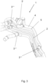
- Figure 3 shows an alternative design of the Figure 2 shown pipe arrangement 1.
- Several functional elements 3 in the form of a check valve 3' and several connectors 3 ⁇ are introduced into the pipe arrangement 1.
- the pipe arrangements 1 shown form a component of an air conditioning circuit of an air conditioning system, wherein the air conditioning system is designed as a mobile air conditioning system of a motor vehicle.
- the pipe arrangements 1 form a component of a temperature control circuit of the drive unit of an electric vehicle, wherein the pipe arrangements 1 supply temperature control medium to the cells of the accumulators as well as to the electrical control components and plug connections.
- the tube arrangement 1 is part of a temperature control device configured to control the temperature of components of the drive unit of electric vehicles. This includes the battery, the power electronics, and the electric motors. Furthermore, the temperature control device is configured to cool the charging electronics and the associated connectors and cables, which is particularly advantageous in connection with rapid charging processes.
- the temperature control device can be configured to control the temperature, in particular to cool, of components of the remaining vehicle electronics.
- components include, for example, sensors and computers for autonomous driving, as well as on-board computers.
- a preform made of polymeric material is provided, wherein the preform is arranged in a blow mold and the preform is blow molded into the shape of a base body 2.
- the molded base body 2 is then opened so that base body sections 6, 7 with a parting surface 8 are created.
- the base body 2 is torn open along the parting surface 8.
- At least one functional element 3 is arranged on at least one base body section 6, 7 such that it can be in contact with the temperature control medium.
- the base body sections 6, 7 are then joined along the parting surface 8 and bonded together to form the tube arrangement 1.
- the bonded connection can be achieved by heating the base body sections 6, 7 along the separating surface, by ultrasonic welding of the base body sections 6, 7 or by means of an adhesive.
Landscapes
- Engineering & Computer Science (AREA)
- Mechanical Engineering (AREA)
- Manufacturing & Machinery (AREA)
- General Engineering & Computer Science (AREA)
- Physics & Mathematics (AREA)
- Thermal Sciences (AREA)
- Life Sciences & Earth Sciences (AREA)
- Sustainable Energy (AREA)
- Power Engineering (AREA)
- Transportation (AREA)
- Sustainable Development (AREA)
- Electrochemistry (AREA)
- Chemical Kinetics & Catalysis (AREA)
- Chemical & Material Sciences (AREA)
- General Chemical & Material Sciences (AREA)
- Geometry (AREA)
- Blow-Moulding Or Thermoforming Of Plastics Or The Like (AREA)
- Air-Conditioning For Vehicles (AREA)
- Secondary Cells (AREA)
- Rigid Pipes And Flexible Pipes (AREA)
- Lining Or Joining Of Plastics Or The Like (AREA)
- Lubrication Details And Ventilation Of Internal Combustion Engines (AREA)
Description
- Die Erfindung betrifft ein Verfahren zur Herstellung einer Rohranordnung für den Transport von Temperiermedium sowie einen Temperierkreislauf.
- Temperiermedien werden in der Elektromobilität benötigt. Akkumulatoren von Elektrofahrzeugen, insbesondere Lithium-Ionen-Akkumulatoren, weisen eine optimale Leistungsfähigkeit nur innerhalb eines begrenzten Temperaturspektrums auf. Daher kann es je nach Umgebungstemperatur erforderlich sein, die Akkumulatoren zu erwärmen oder zu kühlen. Daher weist die Antriebseinheit eines Elektrofahrzeugs in der Regel einen Temperierkreislauf mit einer Rohranordnung auf, durch welchen Temperiermedien zu den Zellen des Akkumulators geleitet werden können, um diese innerhalb eines gewünschten Temperaturspektrums zu temperieren. Aufgrund der Beschränkungen des Bauraums soll die Temperiereinrichtung dabei möglichst kompakt sein.
- Des Weiteren kann es erforderlich sein, Komponenten der gesamten Antriebseinheit von Elektrofahrzeugen zu temperieren, insbesondere zu kühlen. Hierzu gehören neben dem Akkumulator die Leistungselektronik und der Elektromotor. Die Ladeelektronik und die dazugehörigen Steckverbindungen und Leitungen können ebenfalls mittels der Temperiereinrichtung gekühlt werden. Dies ist insbesondere im Zusammenhang mit Schnellladevorgängen relevant.
- Neben dem Einsatz in einer Antriebseinheit ergibt sich ein weiteres Einsatzgebiet im Zusammenhang mit der übrigen Fahrzeugelektronik, hier insbesondere von Sensoren und Bordcomputern. Ist ein Fahrzeug zum autonomen Fahren ausgerüstet, werden leistungsfähige Sensoren und leistungsfähige Rechner benötigt, wobei die Systeme redundant vorhanden sind. Dadurch, dass der Bauraum beschränkt ist, ergibt sich auch bei diesen Systemen ein Bedarf zur Temperierung/Kühlung durch eine Temperiereinrichtung.
- Temperiermedien kommen ferner in Klimaanlagen zum Einsatz. Klimaanlagen, insbesondere mobile Klimaanlagen, umfassen eine Rohranordnung, welche den Transport von Temperiermedium zwischen den einzelnen Aggregaten der Klimaanlage ermöglicht. Bei mobilen Klimaanlagen, beispielsweise bei Klimaanlagen für die Klimatisierung von Innenräumen von Kraftfahrzeugen, ist die Rohranordnung ein vergleichsweise komplexes Gebilde und umfasst häufig Rohre aus verschiedenen Materialien, beispielsweise Rohre aus Metall, Rohrabschnitte aus thermoplastischem Kunststoff und Rohrabschnitte aus gummiartigem Material. Zwar können hierbei die Einsatzbedingungen der Rohrabschnitte optimal auf die jeweiligen Anforderungen abgestimmt werden, die Rohranordnung ist jedoch kostenintensiv, aufwendig in der Montage und schwierig zu recyceln.
-
DE 10 2017 118 134 A1 beschreibt ein Verfahren zum Herstellen eines Rohres für den Transport von Ansaugluft eines Verbrennungsmotors mittels Blasformen. -
JP H05 24101 A -
DE 102 31 866 A1 beschreibt ein Verfahren zur Herstellung eines Kuntstoffhohlkörpers, bei welchem ein Vorformling zu zwei flächigen Halbzeugen aufgeschnitten wird, aus welchen anschließend Halbschalen geformt und zu einem Hohlkörper verbunden werden. - Der Erfindung liegt die Aufgabe zugrunde, eine Rohranordnung für den Transport von Temperiermedium bereitzustellen, welche einfach und kostengünstig herstellbar ist.
- Diese Aufgabe wird mit den Merkmalen von Anspruch 1 gelöst. Auf vorteilhafte Ausgestaltungen nehmen die Unteransprüche Bezug.
- Bei dem erfindungsgemäßen Verfahren zur Herstellung einer Rohranordnung für den Transport von Temperiermedium werden zunächst Grundkörperabschnitte bereitgestellt, welche kongruent ausgestaltete Trennflächen aufweisen, wobei anschließend an zumindest einem Grundkörperabschnitt zumindest ein Funktionselement derart angeordnet wird, dass dieses mit dem Temperiermedium in Kontakt stehen kann, danach werden die Grundkörperabschnitte entlang der Trennfläche gefügt und stoffschlüssig miteinander zur Bildung der Rohranordnung verbunden.
- Rohranordnungen von Temperierkreisläufen enthalten mehrere für die Funktionsfähigkeit der Temperierkreislaufs erforderliche Funktionselemente. Dies sind beispielsweise Drosselventile, Rückschlagventile, schaltbare Ventile, Pumpen, Durchflusssensoren, Verbindungselemente, Konnektoren und Temperatursensoren. Bei der erfindungsgemäßen Rohranordnung ist zumindest eines der Funktionselemente in dem Grundkörper, also innerhalb der Rohranordnung, angeordnet, so dass dieses mit dem Temperiermedium in Kontakt steht.
- Erfindungsgemäß erfolgt die Herstellung der Grundkörperabschnitte, indem ein aus polymerem Material bestehender Vorformling bereitgestellt wird, wobei der Vorformling in einer Blasform angeordnet wird und der Vorformling mittels Blasformen in die Gestalt eines Grundkörpers gebracht wird und der geformte Grundkörper anschließend geöffnet wird, so dass die Grundkörperabschnitte mit der Trennfläche entstehen. Dabei wird der Grundkörper entlang der Trennfläche aufgerissen oder aufgeschnitten. Hierbei ist vorteilhaft, dass die Grundkörperabschnitte schnell und kostengünstig hergestellt werden können. Des Weiteren ergibt sich entlang der Trennfläche eine hervorragende Passform der Grundkörperabschnitte.
- Die Rohranordnung besteht aus einem mittels Blasformen hergestellten Grundkörper aus polymerem Material. Durch das Blasformen ist es möglich, einen Grundkörper mit einer komplexen Gestalt herzustellen. Beispielsweise kann der Grundkörper einen oder mehrere Kanäle umfassen, welche in der für den Montageort erforderlichen Gestalt geformt, beispielsweise gekrümmt, sein können. Des Weiteren ist es besonders einfach, Querschnittsänderungen in die Kanäle einzuformen. Beispielsweise können Abschnitte der Kanäle kreisförmig sein, wohingegen andere Abschnitte der Kanäle nicht rund, beispielsweise oval oder rechteckig, ausgebildet sind. Dadurch kann die Rohranordnung besonders platzsparend ausgebildet und an den Montageort angepasst sein. Dadurch, dass zunächst der Grundkörper geformt, dieser anschließend aufgeschnitten, dann mit Funktionselementen bestückt und wieder gefügt wird, ist es möglich, komplexe Funktionselemente in dem Grundkörper anzuordnen. Des Weiteren können Funktionselemente im Inneren des Grundkörpers angeordnet werden, die nicht geeignet sind, einem Blasformprozess ausgesetzt zu werden, beispielsweise weil die Funktionselemente nicht ausreichend temperatur- oder druckstabil sind.
- Dabei sind die Funktionselemente separat von dem Grundkörper ausgebildet. Daher können die Funktionselemente insbesondere Komponenten aus nichtthermoplastischem Material aufweisen und/oder aktiv steuerbar sein. Derartige Funktionselemente sind beispielsweise Drosselventile aus metallischem Material, schaltbare Ventile, Rückschlagventile mit metallischem Federkörper, Sensoren, beispielsweise Temperatursensoren, Drucksensoren oder Durchflusssensoren, Pumpen, Verbindungselemente oder Konnektoren zum Verbinden der Rohranordnung mit Aggregaten oder dergleichen. Das Funktionselement kann auch als Kühler ausgebildet sein und die Temperatur des Temperiermediums beeinflussen.
- Dabei sind die separat ausgebildeten Funktionselemente innerhalb des Grundkörpers angeordnet. Der Grundkörper wiederum besteht aus einem mittels Blasformen hergestellten Grundkörper aus polymerem Werkstoff, welcher materialeinheitlich und einstückig ausgebildet ist. Nach dem Verschließen der Grundkörperabschnitte sind die Funktionselemente ortsfest in dem Grundkörper angeordnet. Dadurch ist die Herstellung einer funktionalen Rohranordnung mit komplexer Geometrie mit einfachen Verfahrensschritten möglich.
- Zumindest ein weiteres Funktionselement kann aus dem Grundkörper ausgeformt sein. Dazu kann die Blasform derart ausgebildet sein, dass während des Blasformens in den Grundkörper das weitere Funktionselement eingeformt wird. Dies ist insbesondere dann denkbar, wenn das Funktionselement ein passives Funktionselement ist und keinerlei bewegliche Teile aufweist. Beispielsweise kann das Funktionselement ein Drosselventil bilden. Ein Drosselventil, beziehungsweise Expansionsventil, bewirkt durch eine lokale Verengung des Strömungsquerschnitts eine Verminderung des Drucks des durchfließenden Temperiermediums und bewirkt gleichzeitig eine Expansion des Temperiermediums. Das Drosselventil ist dabei als ungeregeltes Drosselventil ausgebildet und bildet eine Einschnürung des Kanals. Dadurch, dass das Drosselventil direkt aus dem Grundkörper ausgeformt ist, ist die Rohranordnung besonders kostengünstig und einfach herstellbar. Das Funktionselement kann auch als Fluidverteilungselement ausgebildet sein. Ferner ist denkbar, dass das Funktionselement als Verbindungselement oder Konnektor ausgebildet ist. Dadurch kann die Rohranordnung ausgerüstet sein, mit weiteren Komponenten eines Temperierkreislaufs verbunden zu werden.
- In den Grundkörper wird zumindest ein Kanal eingeformt, wobei das zumindest eine Funktionselement in dem Kanal angeordnet wird. Dadurch steht das Funktionselement in unmittelbarem Kontakt mit dem Temperiermedium und kann entweder direkt den Volumenstrom des Temperiermediums beeinflussen oder direkt Zustandsdaten des Temperiermediums, wie Temperatur, Volumenstrom oder Druck, erfassen.
- Erfindungsgemäß werden in den Grundkörper mehrere Kanäle eingeformt, wobei zwischen den Kanälen eine Kanalwand geformt wird. Dadurch kann der Grundkörper verschiedene Rohrabschnitte eines Klimakreislaufs aufnehmen, beispielsweise den Kanalabschnitt vor und hinter einem Verdampfer. Durch die Kanalwand sind beide Volumenströme voneinander getrennt.
- In einer erfindungsgemäßen Verwendung bildet die Rohranordnung einen Teil eines Temperierkreislaufs.
- Gemäß einer ersten Ausgestaltung ist die Rohranordnung Teil eines Klimakreislaufs einer Klimaanlage. Dabei kann die Klimaanlage insbesondere als mobile Klimaanlage ausgebildet sein. Die mobile Klimaanlage wiederum kann Bestandteil eines Kraftfahrzeugs sein, wobei die Klimaanlage der Klimatisierung des Fahrzeuginnenraums dient. Dadurch, dass der Grundkörper der Rohranordnung zwar eine komplexe Geometrie aufweisen und mehrere Funktionselemente beinhalten kann, ist die Rohranordnung dennoch einfach zu montieren und weist nur wenige Teile auf. Insofern vereinfacht die erfindungsgemäße Rohranordnung die Komplexität insbesondere einer mobilen Klimaanlage eines Kraftfahrzeugs. Dies ist insbesondere in Bezug auf elektrisch angetriebene Kraftfahrzeuge vorteilhaft, da diese aufgrund des für den Elektroantrieb erforderlichen Akkumulators nur über einen sehr beschränkten Bauraum verfügen. Das Blasformverfahren ermöglicht es, dass die Rohranordnung an den zur Verfügung stehenden Bauraum angepasst ist, wobei die Kanäle für den Transport von Temperiermedium so bemessen sind, dass ein optimaler Transport von Temperiermedium möglich ist.
- Gemäß einer zweiten Ausgestaltung ist die Rohranordnung Teil eines Temperierkreislaufs der Antriebseinheit eines Elektrofahrzeugs. Dabei führt die Rohranordnung den zu temperierenden Elementen der Antriebseinheit Temperiermedium zu, so dass die Elemente innerhalb eines gewünschten Temperaturspektrums temperiert werden können. Beispielsweise können die Akkumulatoren je nach Anforderung erwärmt oder gekühlt werden. Des Weiteren können die Elektromotoren sowie Komponenten der Leistungselektronik und auch Steckverbindungen mittels Temperiermedium gekühlt werden. Die Kühlung von Steckverbindungen ist dabei insbesondere bei Schnellladevorgängen vorteilhaft, da beim Schnellladen aufgrund der hohen Ladeströme starke Erwärmungen an Steckverbindungen auftreten können. Dadurch, dass die Rohranordnung im Blasformen geformt ist, kann die Rohranordnung in einer großen Formenvielfalt hergestellt werden. Dies ist insbesondere im Hinblick auf den für eine Rohranordnung beschränkten und komplex geformten Bauraum der zuvor genannten Komponenten vorteilhaft.
- Gemäß einer dritten Ausgestaltung ist die Rohranordnung Teil einer Temperiereinrichtung, welche eingerichtet ist, Komponenten der Fahrzeugelektronik zu temperieren, insbesondere zu kühlen. Komponenten der Fahrzeugelektronik sind dabei beispielsweise Sensoren und Rechner für das autonome Fahren sowie Bordcomputer.
- Einige Ausgestaltungen der erfindungsgemäßen Rohranordnung werden nachfolgenden anhand der Figuren näher erläutert. Diese zeigen, jeweils schematisch:
- Fig. 1
- eine Rohranordnung mit einem in den Grundkörper eingeformten Drosselventil;
- Fig. 2
- eine Rohranordnung mit mehreren separat ausgebildeten Funktionselementen;
- Fig. 3
- eine weitere Rohranordnung mit mehreren separat ausgebildeten Funktionselementen.
-
Figur 1 zeigt eine Rohranordnung 1 für den Transport von Temperiermedium,
umfassend einen mittels Blasformen hergestellten Grundkörper 2 aus polymerem Werkstoff. In dem Grundkörper 2 ist zumindest ein Funktionselement 3 angeordnet, welches mit dem Temperiermedium in Kontakt steht. Das Funktionselement 3 ist in einem Kanal 4 angeordnet, wobei das Funktionselement 3 einstückig aus dem Grundkörper 2 ausgeformt ist. Das Funktionselement 3 bildet ein Drosselventil und ist durch eine Querschnittsverengung des Kanals 4 ausgebildet. -
Figur 2 zeigt eine Rohranordnung 1 gemäßFigur 1 , wobei der Grundkörper 2 mehrere Funktionselemente 3 umfasst, welche separat von dem Grundkörper 2 ausgebildet und im Inneren des Grundkörpers 2 angeordnet sind. Der Grundkörper 2 weist mehrere Kanäle 4 auf, wobei sich zwischen den Kanälen 4 jeweils eine Kanalwand 5 befindet. - Die Rohranordnung 1 umfasst mehrere Funktionselemente 3, unter anderem ein Rückschlagventil 3', einen Temperatursensor, einen Drucksensor, einen Durchflusssensor sowie einen Konnektor in Form eines Anschlussblocks 3" zum Anschluss der Rohranordnung 1 an angrenzende Aggregate oder Rohrleitungen. Des Weiteren weist die Rohranordnung 1 ein direkt in einen Kanal 4 eingeformtes Drosselventil 3‴ auf, welches materialeinheitlich und einstückig aus dem Grundkörper 2 ausgeformt ist.
-
Figur 3 zeigt eine alternative Ausgestaltung der inFigur 2 gezeigten Rohranordnung 1. In die Rohranordnung 1 sind mehrere Funktionselemente 3 in Form eines Rückschlagventils 3' und mehrerer Konnektoren 3ʺʺ eingebracht. - Die in den
Figuren 1 bis 3 gezeigten Rohranordnungen 1 bilden einen Bestandteil eines Klimakreislaufs einer Klimaanlage, wobei die Klimaanlage als mobile Klimaanlage eines Kraftfahrzeugs ausgebildet ist. Gemäß einer weiteren Ausgestaltung bilden die Rohranordnungen 1 einen Bestandteil eines Temperierkreislaufs der Antriebseinheit eines Elektrofahrzeugs, wobei die Rohranordnungen 1 Temperiermedium den Zellen der Akkumulatoren sowie den elektrischen Steuerungskomponenten und Steckverbindungen zuführen. - In einer weiteren Ausgestaltung ist die Rohranordnung 1 Bestandteil einer Temperiereinrichtung, welche eingerichtet ist, Komponenten der Antriebseinheit von Elektrofahrzeugen zu temperieren. Hierzu gehören neben dem Akkumulator die Leistungselektronik und die Elektromotoren. Des Weiteren ist die Temperiereinrichtung eingerichtet, die Ladeelektronik und die dazugehörigen Steckverbindungen und Leitungen zu kühlen, was insbesondere im Zusammenhang mit Schnellladevorgängen vorteilhaft ist.
- Ferner kann die Temperiereinrichtung eingerichtet sein, Komponenten der übrigen Fahrzeugelektronik zu temperieren, insbesondere zu kühlen. Derartige Komponenten sind beispielsweise Sensoren und Rechner für das autonome Fahren sowie Bordcomputer.
- Bei dem erfindungsgemäßen Verfahren zur Herstellung einer Rohranordnung 1 für den Transport von Temperiermedium gemäß einer der
Figuren 1 bis 3 wird zunächst ein aus polymerem Material bestehender Vorformling bereitgestellt, wobei der Vorformling in einer Blasform angeordnet wird und der Vorformling mittels Blasformen in die Gestalt eines Grundkörpers 2 gebracht wird. Anschließend wird der geformte Grundkörper 2 geöffnet, so dass Grundkörperabschnitte 6, 7 mit einer Trennfläche 8 entstehen. Hierzu wird der Grundkörper 2 entlang der Trennfläche 8 aufgerissen. An zumindest einem Grundkörperabschnitt 6, 7 wird zumindest ein Funktionselement 3 derart angeordnet, dass dieses mit dem Temperiermedium in Kontakt stehen kann. Danach werden die Grundkörperabschnitte 6, 7 entlang der Trennfläche 8 gefügt und stoffschlüssig miteinander zur Bildung der Rohranordnung 1 verbunden. Die stoffschlüssige Verbindung kann durch Erwärmen der Grundkörperabschnitte 6, 7 entlang der Trennfläche, durch Ultraschallschweißen der Grundkörperabschnitte 6, 7 oder mittels eines Klebemittels erfolgen.
Claims (5)
- Verfahren zur Herstellung einer Rohranordnung (1) für den Transport von Temperiermedium, bei welchem Grundkörperabschnitte (6, 7) bereitgestellt werden, welche kongruent ausgestaltete Trennflächen (8) aufweisen, wobei ein aus polymerem Material bestehender Vorformling bereitgestellt wird, wobei der Vorformling in einer Blasform angeordnet wird und der Vorformling mittels Blasformen in die Gestalt eines Grundkörpers (2) gebracht wird, wobei in den Grundkörper (2) mehrere Kanäle (4) eingeformt werden, wobei sich zwischen den Kanälen (4) eine Kanalwand (5) befindet, wobei der geformte Grundkörper (2) geöffnet wird, so dass die Grundkörperabschnitte (6, 7) mit der Trennfläche (8) entstehen, wobei der Grundkörper (2) zum Herstellen der Grundkörperabschnitte (6, 7) entlang der Trennfläche (8) aufgerissen oder aufgeschnitten wird, wobei an zumindest einem Grundkörperabschnitt (6, 7) zumindest ein Funktionselement (3) derart angeordnet wird, dass dieses mit dem Temperiermedium in Kontakt stehen kann, wobei das zumindest eine Funktionselement (3) in einem Kanal (4) angeordnet wird, danach werden die Grundkörperabschnitte (6, 7) entlang der Trennfläche (8) gefügt und stoffschlüssig miteinander zur Bildung der Rohranordnung (1) verbunden.
- Verfahren nach Anspruch 1, dadurch gekennzeichnet, dass die Blasform derart ausgebildet ist, dass während des Blasformens in den Grundkörper (2) zumindest ein weiteres Funktionselement (3') eingeformt wird.
- Verfahren nach Anspruch 2, dadurch gekennzeichnet, dass das aus dem Grundkörper (2) ausgeformte weitere Funktionselement (3') ein Drosselventil, Verbindungselement oder Konnektor bildet.
- Verfahren nach einem der Ansprüche 1 bis 3, dadurch gekennzeichnet, dass das zumindest eine Funktionselement (3) als Ventil, Drosselventil, Rückschlagventil, Sensor, Pumpe, Verbindungselement oder Konnektor ausgebildet ist.
- Temperierkreislauf, umfassend eine Rohranordnung (1), erhältlich nach einem der vorherigen Ansprüche.
Priority Applications (6)
| Application Number | Priority Date | Filing Date | Title |
|---|---|---|---|
| EP20178064.0A EP3919262B1 (de) | 2020-06-03 | 2020-06-03 | Verfahren zur herstellung einer rohranordnung für den transport von temperiermedium |
| JP2021089310A JP7305705B2 (ja) | 2020-06-03 | 2021-05-27 | 温度制御媒体の輸送用管路装置の製造方法 |
| CN202110610236.7A CN113752781B (zh) | 2020-06-03 | 2021-06-01 | 用于制造用于运输调温介质的管装置的方法 |
| MX2021006512A MX2021006512A (es) | 2020-06-03 | 2021-06-02 | Metodo para producir una disposicion de tubos para el transporte de medio de control de temperatura. |
| US17/338,061 US12023844B2 (en) | 2020-06-03 | 2021-06-03 | Method for producing a tube arrangement for the transport of tempering medium |
| KR1020210072001A KR20210150306A (ko) | 2020-06-03 | 2021-06-03 | 온도 제어 매질의 수송을 위한 튜브 장치를 제조하는 방법 |
Applications Claiming Priority (1)
| Application Number | Priority Date | Filing Date | Title |
|---|---|---|---|
| EP20178064.0A EP3919262B1 (de) | 2020-06-03 | 2020-06-03 | Verfahren zur herstellung einer rohranordnung für den transport von temperiermedium |
Publications (3)
| Publication Number | Publication Date |
|---|---|
| EP3919262A1 EP3919262A1 (de) | 2021-12-08 |
| EP3919262B1 true EP3919262B1 (de) | 2025-05-07 |
| EP3919262C0 EP3919262C0 (de) | 2025-05-07 |
Family
ID=70977448
Family Applications (1)
| Application Number | Title | Priority Date | Filing Date |
|---|---|---|---|
| EP20178064.0A Active EP3919262B1 (de) | 2020-06-03 | 2020-06-03 | Verfahren zur herstellung einer rohranordnung für den transport von temperiermedium |
Country Status (6)
| Country | Link |
|---|---|
| US (1) | US12023844B2 (de) |
| EP (1) | EP3919262B1 (de) |
| JP (1) | JP7305705B2 (de) |
| KR (1) | KR20210150306A (de) |
| CN (1) | CN113752781B (de) |
| MX (1) | MX2021006512A (de) |
Families Citing this family (3)
| Publication number | Priority date | Publication date | Assignee | Title |
|---|---|---|---|---|
| KR20250067151A (ko) | 2022-09-26 | 2025-05-14 | 티아이 그룹 오토모티브 시스템즈 엘엘씨 | 열 전달을 제공하기 위한 이중-벽 배터리 인클로저 |
| EP4592054B1 (de) * | 2024-01-29 | 2025-11-26 | TI Automotive Technology Center GmbH | Verfahren zur herstellung einer rohranordnung |
| DE102024111458A1 (de) * | 2024-04-24 | 2025-10-30 | Ti Automotive Technology Center Gmbh | Stabiles, schlankes Modul für einen Temperiermittelkreislauf |
Family Cites Families (20)
| Publication number | Priority date | Publication date | Assignee | Title |
|---|---|---|---|---|
| JP2585255B2 (ja) * | 1987-04-04 | 1997-02-26 | オ−エム工業株式会社 | 自動車用給油管 |
| GB8808944D0 (en) * | 1988-04-15 | 1988-05-18 | Du Pont Canada | Method for manufacture of thermoplastic panel heat exchangers |
| DE4013471A1 (de) * | 1990-04-27 | 1991-10-31 | Fischer Ag Georg | Einrichtung zum stirnseitigen verschweissen von kunststoffteilen |
| JP2959207B2 (ja) * | 1991-07-19 | 1999-10-06 | 石川島播磨重工業株式会社 | 親子パイプのブロー成形方法 |
| JPH0550495A (ja) * | 1991-08-21 | 1993-03-02 | Ishikawajima Harima Heavy Ind Co Ltd | ブロー成形装置 |
| JPH0857963A (ja) * | 1994-08-19 | 1996-03-05 | Sekisui Chem Co Ltd | 熱可塑性樹脂管材の突合せ溶接方法 |
| JPH0868490A (ja) * | 1994-08-26 | 1996-03-12 | Excel Kk | 消音器部を有する中空成形体 |
| US6660198B1 (en) * | 2000-09-19 | 2003-12-09 | Marconi Communications, Inc. | Process for making a plastic counterflow heat exchanger |
| DE10231866A1 (de) * | 2002-07-12 | 2004-01-22 | Basell Polyolefine Gmbh | Mehrstufiges Verfahren zur Herstellung von Kunststoffhohlkörpern aus Halbschalen |
| JP4229231B2 (ja) | 2003-09-19 | 2009-02-25 | 学校法人日本大学 | アナログ・デジタル変換方法 |
| JP4232709B2 (ja) * | 2004-07-28 | 2009-03-04 | 日産自動車株式会社 | 二重管エキゾーストマニホールド |
| US8431067B2 (en) * | 2007-03-06 | 2013-04-30 | Mercury Plastics, Inc. | Method for making a reservoir |
| JP2009023179A (ja) * | 2007-07-18 | 2009-02-05 | Towa Buroo Kk | フランジ付樹脂チューブの製造方法 |
| US8377368B2 (en) * | 2009-12-11 | 2013-02-19 | Ti Automotive Technology Center Gmbh | Component mounting arrangement |
| US9660235B2 (en) * | 2012-02-18 | 2017-05-23 | Johnson Controls Advanced Power Solutions Gmbh | Assembly with a first and a second component and method for producing such an assembly |
| JP6347139B2 (ja) * | 2014-04-07 | 2018-06-27 | キョーラク株式会社 | 中空成形品 |
| DE102017118134A1 (de) * | 2016-08-10 | 2018-02-15 | Ford Motor Company | Verfahren zum Herstellen eines Reihengehäuses für ein in einem Rohr eingeschlossenes Bauteil |
| JP6777853B2 (ja) * | 2016-09-28 | 2020-10-28 | キョーラク株式会社 | 成形品の製造方法 |
| DE102016119944B4 (de) * | 2016-10-19 | 2025-08-07 | Windmöller & Hölscher Kg | Blaskopf für eine Blasextrusionsvorrichtung, Verfahren zur Herstellung einer Blasfolie, Düsenvorrichtung für einen Blaskopf, Grundkörper zur Verwendung in einem Blaskopf, Temperiervorrichtung zum Temperieren einer Materialschmelze in einem Blaskopf sowie Blasextrusionsvorrichtung mit einem Blaskopf |
| DE102018118177A1 (de) * | 2018-07-27 | 2020-01-30 | Fahrenheit Gmbh | Temperierelement mit Sorptionsmaterial, insbesondere zur Temperierung einer Batteriezelleneinheit eines Kraftfahrzeugs |
-
2020
- 2020-06-03 EP EP20178064.0A patent/EP3919262B1/de active Active
-
2021
- 2021-05-27 JP JP2021089310A patent/JP7305705B2/ja active Active
- 2021-06-01 CN CN202110610236.7A patent/CN113752781B/zh active Active
- 2021-06-02 MX MX2021006512A patent/MX2021006512A/es unknown
- 2021-06-03 KR KR1020210072001A patent/KR20210150306A/ko active Pending
- 2021-06-03 US US17/338,061 patent/US12023844B2/en active Active
Also Published As
| Publication number | Publication date |
|---|---|
| JP2022001427A (ja) | 2022-01-06 |
| CN113752781B (zh) | 2024-03-12 |
| CN113752781A (zh) | 2021-12-07 |
| EP3919262C0 (de) | 2025-05-07 |
| EP3919262A1 (de) | 2021-12-08 |
| US12023844B2 (en) | 2024-07-02 |
| KR20210150306A (ko) | 2021-12-10 |
| US20210379811A1 (en) | 2021-12-09 |
| MX2021006512A (es) | 2021-12-06 |
| JP7305705B2 (ja) | 2023-07-10 |
Similar Documents
| Publication | Publication Date | Title |
|---|---|---|
| EP3919299B1 (de) | Rohranordnung für den transport von temperiermedium | |
| EP3919262B1 (de) | Verfahren zur herstellung einer rohranordnung für den transport von temperiermedium | |
| EP3295509B1 (de) | Energiespeicher eines kraftfahrzeugs | |
| EP2697036B1 (de) | Saugmodul und zugehöriges herstellungsverfahren | |
| DE102016217361A1 (de) | Rotatorische Elektromaschine | |
| WO2012130406A1 (de) | Batterietemperiersystem, kraftfahrzeug mit einem batterietemperiersystem sowie verfahren zum betreiben eines batterietemperiersystems | |
| DE10253852A1 (de) | Thermoplastischer Wärmetauscher | |
| EP4067048B1 (de) | Verfahren zur herstellung einer anordnung für den transport von medien und anordnung | |
| WO2014000995A1 (de) | Thermomanagementmodul mit mehrteiligem gehäuse | |
| EP3964374B1 (de) | Rohranordnung für den transport von temperiermedien | |
| DE102019212861A1 (de) | Batteriemodul für ein Kraftfahrzeug, Herstellungsverfahren für ein Batteriemodul und Kraftfahrzeug mit einem Batteriemodul | |
| WO2017072192A1 (de) | Fluidsystem mit verbindungsbauteil | |
| WO2024078734A1 (de) | Thermomanagementsystem und fahrzeug mit zumindest einem solchen | |
| DE102022004859A1 (de) | Thermomanagementsystem und Fahrzeug mit zumindest einem solchen | |
| DE102019133567A1 (de) | Kühlvorrichtung sowie ein Batteriesystem für ein Kraftfahrzeug und ein Verfahren hierzu | |
| DE102015008942A1 (de) | Temperiervorrichtung für eine elektrische Batterie und Fahrzeug | |
| DE102018201526A1 (de) | Speichereinrichtung zum Speichern von elektrischer Energie für ein Kraftfahrzeug, sowie Kraftfahrzeug | |
| EP4300027A1 (de) | Anordnung für den transport von medien | |
| DE102023132359A1 (de) | Mehrschichtiges Spritzgussbauteil und Verfahren zur Herstellung eines solchen Bauteils | |
| EP3979393B1 (de) | Energiespeichersystem mit temperiereinrichtung | |
| EP4592054B1 (de) | Verfahren zur herstellung einer rohranordnung | |
| DE102023113877A1 (de) | Gehäuse für eine Batterie, Batterie mit dem Gehäuse, Verfahren zum Herstellen der Batterie und Kraftfahrzeug | |
| EP4382783A1 (de) | Rückschlagventil | |
| DE102024131319A1 (de) | Teilesatz, Fahrzeuge, Verteiler, Wärmetauschersystem und Verfahren | |
| EP4401196A1 (de) | Mehrkanaltemperiervorrichtung, batteriegehäuse sowie verwendung einer mehrkanaltemperiervorrichtung |
Legal Events
| Date | Code | Title | Description |
|---|---|---|---|
| PUAI | Public reference made under article 153(3) epc to a published international application that has entered the european phase |
Free format text: ORIGINAL CODE: 0009012 |
|
| STAA | Information on the status of an ep patent application or granted ep patent |
Free format text: STATUS: THE APPLICATION HAS BEEN PUBLISHED |
|
| STAA | Information on the status of an ep patent application or granted ep patent |
Free format text: STATUS: REQUEST FOR EXAMINATION WAS MADE |
|
| AK | Designated contracting states |
Kind code of ref document: A1 Designated state(s): AL AT BE BG CH CY CZ DE DK EE ES FI FR GB GR HR HU IE IS IT LI LT LU LV MC MK MT NL NO PL PT RO RS SE SI SK SM TR |
|
| B565 | Issuance of search results under rule 164(2) epc |
Effective date: 20201020 |
|
| 17P | Request for examination filed |
Effective date: 20211104 |
|
| RBV | Designated contracting states (corrected) |
Designated state(s): AL AT BE BG CH CY CZ DE DK EE ES FI FR GB GR HR HU IE IS IT LI LT LU LV MC MK MT NL NO PL PT RO RS SE SI SK SM TR |
|
| STAA | Information on the status of an ep patent application or granted ep patent |
Free format text: STATUS: EXAMINATION IS IN PROGRESS |
|
| P01 | Opt-out of the competence of the unified patent court (upc) registered |
Effective date: 20230524 |
|
| 17Q | First examination report despatched |
Effective date: 20230612 |
|
| GRAP | Despatch of communication of intention to grant a patent |
Free format text: ORIGINAL CODE: EPIDOSNIGR1 |
|
| STAA | Information on the status of an ep patent application or granted ep patent |
Free format text: STATUS: GRANT OF PATENT IS INTENDED |
|
| RIC1 | Information provided on ipc code assigned before grant |
Ipc: F28D 21/00 20060101ALN20250205BHEP Ipc: B29L 31/18 20060101ALN20250205BHEP Ipc: B29L 31/00 20060101ALN20250205BHEP Ipc: B29L 23/00 20060101ALN20250205BHEP Ipc: B29C 65/00 20060101ALN20250205BHEP Ipc: B29C 65/48 20060101ALN20250205BHEP Ipc: B29C 65/08 20060101ALN20250205BHEP Ipc: B29C 49/42 20060101ALN20250205BHEP Ipc: F28F 21/06 20060101ALI20250205BHEP Ipc: F28F 1/02 20060101ALI20250205BHEP Ipc: F28D 1/04 20060101ALI20250205BHEP Ipc: B29C 69/00 20060101AFI20250205BHEP |
|
| RIC1 | Information provided on ipc code assigned before grant |
Ipc: F28D 21/00 20060101ALN20250219BHEP Ipc: B29L 31/18 20060101ALN20250219BHEP Ipc: B29L 31/00 20060101ALN20250219BHEP Ipc: B29L 23/00 20060101ALN20250219BHEP Ipc: B29C 65/00 20060101ALN20250219BHEP Ipc: B29C 65/48 20060101ALN20250219BHEP Ipc: B29C 65/08 20060101ALN20250219BHEP Ipc: B29C 49/42 20060101ALN20250219BHEP Ipc: F28F 21/06 20060101ALI20250219BHEP Ipc: F28F 1/02 20060101ALI20250219BHEP Ipc: F28D 1/04 20060101ALI20250219BHEP Ipc: B29C 69/00 20060101AFI20250219BHEP |
|
| GRAS | Grant fee paid |
Free format text: ORIGINAL CODE: EPIDOSNIGR3 |
|
| INTG | Intention to grant announced |
Effective date: 20250228 |
|
| GRAA | (expected) grant |
Free format text: ORIGINAL CODE: 0009210 |
|
| STAA | Information on the status of an ep patent application or granted ep patent |
Free format text: STATUS: THE PATENT HAS BEEN GRANTED |
|
| AK | Designated contracting states |
Kind code of ref document: B1 Designated state(s): AL AT BE BG CH CY CZ DE DK EE ES FI FR GB GR HR HU IE IS IT LI LT LU LV MC MK MT NL NO PL PT RO RS SE SI SK SM TR |
|
| REG | Reference to a national code |
Ref country code: GB Ref legal event code: FG4D Free format text: NOT ENGLISH |
|
| REG | Reference to a national code |
Ref country code: CH Ref legal event code: EP |
|
| REG | Reference to a national code |
Ref country code: DE Ref legal event code: R096 Ref document number: 502020010989 Country of ref document: DE |
|
| REG | Reference to a national code |
Ref country code: IE Ref legal event code: FG4D Free format text: LANGUAGE OF EP DOCUMENT: GERMAN |
|
| U01 | Request for unitary effect filed |
Effective date: 20250528 |
|
| P04 | Withdrawal of opt-out of the competence of the unified patent court (upc) registered |
Free format text: CASE NUMBER: APP_26402/2025 Effective date: 20250603 |
|
| U07 | Unitary effect registered |
Designated state(s): AT BE BG DE DK EE FI FR IT LT LU LV MT NL PT RO SE SI Effective date: 20250606 |
|
| U20 | Renewal fee for the european patent with unitary effect paid |
Year of fee payment: 6 Effective date: 20250828 |
|
| PG25 | Lapsed in a contracting state [announced via postgrant information from national office to epo] |
Ref country code: ES Free format text: LAPSE BECAUSE OF FAILURE TO SUBMIT A TRANSLATION OF THE DESCRIPTION OR TO PAY THE FEE WITHIN THE PRESCRIBED TIME-LIMIT Effective date: 20250507 |
|
| PG25 | Lapsed in a contracting state [announced via postgrant information from national office to epo] |
Ref country code: NO Free format text: LAPSE BECAUSE OF FAILURE TO SUBMIT A TRANSLATION OF THE DESCRIPTION OR TO PAY THE FEE WITHIN THE PRESCRIBED TIME-LIMIT Effective date: 20250807 Ref country code: GR Free format text: LAPSE BECAUSE OF FAILURE TO SUBMIT A TRANSLATION OF THE DESCRIPTION OR TO PAY THE FEE WITHIN THE PRESCRIBED TIME-LIMIT Effective date: 20250808 |
|
| PG25 | Lapsed in a contracting state [announced via postgrant information from national office to epo] |
Ref country code: PL Free format text: LAPSE BECAUSE OF FAILURE TO SUBMIT A TRANSLATION OF THE DESCRIPTION OR TO PAY THE FEE WITHIN THE PRESCRIBED TIME-LIMIT Effective date: 20250507 |
|
| PG25 | Lapsed in a contracting state [announced via postgrant information from national office to epo] |
Ref country code: HR Free format text: LAPSE BECAUSE OF FAILURE TO SUBMIT A TRANSLATION OF THE DESCRIPTION OR TO PAY THE FEE WITHIN THE PRESCRIBED TIME-LIMIT Effective date: 20250507 |
|
| PG25 | Lapsed in a contracting state [announced via postgrant information from national office to epo] |
Ref country code: RS Free format text: LAPSE BECAUSE OF FAILURE TO SUBMIT A TRANSLATION OF THE DESCRIPTION OR TO PAY THE FEE WITHIN THE PRESCRIBED TIME-LIMIT Effective date: 20250807 |
|
| PG25 | Lapsed in a contracting state [announced via postgrant information from national office to epo] |
Ref country code: IS Free format text: LAPSE BECAUSE OF FAILURE TO SUBMIT A TRANSLATION OF THE DESCRIPTION OR TO PAY THE FEE WITHIN THE PRESCRIBED TIME-LIMIT Effective date: 20250907 |
|
| PG25 | Lapsed in a contracting state [announced via postgrant information from national office to epo] |
Ref country code: SM Free format text: LAPSE BECAUSE OF FAILURE TO SUBMIT A TRANSLATION OF THE DESCRIPTION OR TO PAY THE FEE WITHIN THE PRESCRIBED TIME-LIMIT Effective date: 20250507 |
|
| PG25 | Lapsed in a contracting state [announced via postgrant information from national office to epo] |
Ref country code: CZ Free format text: LAPSE BECAUSE OF FAILURE TO SUBMIT A TRANSLATION OF THE DESCRIPTION OR TO PAY THE FEE WITHIN THE PRESCRIBED TIME-LIMIT Effective date: 20250507 |
|
| PG25 | Lapsed in a contracting state [announced via postgrant information from national office to epo] |
Ref country code: SK Free format text: LAPSE BECAUSE OF FAILURE TO SUBMIT A TRANSLATION OF THE DESCRIPTION OR TO PAY THE FEE WITHIN THE PRESCRIBED TIME-LIMIT Effective date: 20250507 |
|
| REG | Reference to a national code |
Ref country code: CH Ref legal event code: H13 Free format text: ST27 STATUS EVENT CODE: U-0-0-H10-H13 (AS PROVIDED BY THE NATIONAL OFFICE) Effective date: 20260127 |