EP3919183A1 - Cart for storing and heating at least one gluing device - Google Patents
Cart for storing and heating at least one gluing device Download PDFInfo
- Publication number
- EP3919183A1 EP3919183A1 EP21177638.0A EP21177638A EP3919183A1 EP 3919183 A1 EP3919183 A1 EP 3919183A1 EP 21177638 A EP21177638 A EP 21177638A EP 3919183 A1 EP3919183 A1 EP 3919183A1
- Authority
- EP
- European Patent Office
- Prior art keywords
- container
- heating
- cart
- gluing device
- glue
- Prior art date
- Legal status (The legal status is an assumption and is not a legal conclusion. Google has not performed a legal analysis and makes no representation as to the accuracy of the status listed.)
- Pending
Links
Images


Classifications
-
- B—PERFORMING OPERATIONS; TRANSPORTING
- B05—SPRAYING OR ATOMISING IN GENERAL; APPLYING FLUENT MATERIALS TO SURFACES, IN GENERAL
- B05C—APPARATUS FOR APPLYING FLUENT MATERIALS TO SURFACES, IN GENERAL
- B05C11/00—Component parts, details or accessories not specifically provided for in groups B05C1/00 - B05C9/00
- B05C11/10—Storage, supply or control of liquid or other fluent material; Recovery of excess liquid or other fluent material
- B05C11/1042—Storage, supply or control of liquid or other fluent material; Recovery of excess liquid or other fluent material provided with means for heating or cooling the liquid or other fluent material in the supplying means upstream of the applying apparatus
-
- B—PERFORMING OPERATIONS; TRANSPORTING
- B27—WORKING OR PRESERVING WOOD OR SIMILAR MATERIAL; NAILING OR STAPLING MACHINES IN GENERAL
- B27G—ACCESSORY MACHINES OR APPARATUS FOR WORKING WOOD OR SIMILAR MATERIALS; TOOLS FOR WORKING WOOD OR SIMILAR MATERIALS; SAFETY DEVICES FOR WOOD WORKING MACHINES OR TOOLS
- B27G11/00—Applying adhesives or glue to surfaces of wood to be joined
- B27G11/02—Glue vessels; Apparatus for warming or heating glue
-
- B—PERFORMING OPERATIONS; TRANSPORTING
- B29—WORKING OF PLASTICS; WORKING OF SUBSTANCES IN A PLASTIC STATE IN GENERAL
- B29B—PREPARATION OR PRETREATMENT OF THE MATERIAL TO BE SHAPED; MAKING GRANULES OR PREFORMS; RECOVERY OF PLASTICS OR OTHER CONSTITUENTS OF WASTE MATERIAL CONTAINING PLASTICS
- B29B13/00—Conditioning or physical treatment of the material to be shaped
- B29B13/02—Conditioning or physical treatment of the material to be shaped by heating
- B29B13/022—Melting the material to be shaped
-
- B—PERFORMING OPERATIONS; TRANSPORTING
- B05—SPRAYING OR ATOMISING IN GENERAL; APPLYING FLUENT MATERIALS TO SURFACES, IN GENERAL
- B05C—APPARATUS FOR APPLYING FLUENT MATERIALS TO SURFACES, IN GENERAL
- B05C1/00—Apparatus in which liquid or other fluent material is applied to the surface of the work by contact with a member carrying the liquid or other fluent material, e.g. a porous member loaded with a liquid to be applied as a coating
- B05C1/006—Apparatus in which liquid or other fluent material is applied to the surface of the work by contact with a member carrying the liquid or other fluent material, e.g. a porous member loaded with a liquid to be applied as a coating for applying liquid or other fluent material to the edges of essentially flat articles
-
- B—PERFORMING OPERATIONS; TRANSPORTING
- B05—SPRAYING OR ATOMISING IN GENERAL; APPLYING FLUENT MATERIALS TO SURFACES, IN GENERAL
- B05C—APPARATUS FOR APPLYING FLUENT MATERIALS TO SURFACES, IN GENERAL
- B05C1/00—Apparatus in which liquid or other fluent material is applied to the surface of the work by contact with a member carrying the liquid or other fluent material, e.g. a porous member loaded with a liquid to be applied as a coating
- B05C1/04—Apparatus in which liquid or other fluent material is applied to the surface of the work by contact with a member carrying the liquid or other fluent material, e.g. a porous member loaded with a liquid to be applied as a coating for applying liquid or other fluent material to work of indefinite length
- B05C1/08—Apparatus in which liquid or other fluent material is applied to the surface of the work by contact with a member carrying the liquid or other fluent material, e.g. a porous member loaded with a liquid to be applied as a coating for applying liquid or other fluent material to work of indefinite length using a roller or other rotating member which contacts the work along a generating line
-
- B—PERFORMING OPERATIONS; TRANSPORTING
- B27—WORKING OR PRESERVING WOOD OR SIMILAR MATERIAL; NAILING OR STAPLING MACHINES IN GENERAL
- B27D—WORKING VENEER OR PLYWOOD
- B27D5/00—Other working of veneer or plywood specially adapted to veneer or plywood
- B27D5/003—Other working of veneer or plywood specially adapted to veneer or plywood securing a veneer strip to a panel edge
Definitions
- the present invention relates to a cart for storing and heating at least one gluing device.
- the invention relates to the structure of a cart designed to contain one or more gluing devices and to allow the flow of an electric current in the gluing device, so that the amount of glue contained in said gluing device is subjected to a heating process to allow the application of said amount of glue on a workpiece, such as a wooden panel or on another material.
- the gluing device comprises a receptacle containing a quantity of solid glue and electric heating means for heating said quantity of solid glue, and the cart is equipped with power supply means for supplying said electric heating means.
- Said gluing device can be equipped with at least one roller to apply said quantity of glue on a workpiece or it can be without a roller.
- edge-banding machines are used to edge-band the side surfaces of said panel, i.e., to apply an edge tape or band on said side surfaces.
- the panel edge-banding process involves a panel rectification step, in which the inaccuracies of a side surface of the panel are removed (for example an inaccuracy can be an amount of excess material on the side surface of the panel), a step of applying glue on said side surface for gluing an edge-band on said side surface, and a step of finishing of said edge by means of one or more working tools (such as for example a rounder) according to the finishing type.
- a panel rectification step in which the inaccuracies of a side surface of the panel are removed (for example an inaccuracy can be an amount of excess material on the side surface of the panel), a step of applying glue on said side surface for gluing an edge-band on said side surface, and a step of finishing of said edge by means of one or more working tools (such as for example a rounder) according to the finishing type.
- the glue In order that the glue be correctly applied on a side surface of the panel it is essential that the glue is heated, i.e., reaches the melting temperature.
- the melting temperature can change according to the type of glue.
- the glue is a solid glue and is contained in a receptacle of a gluing device (called “glue tank”) and said gluing device can be removably coupled to the edge-banding machine.
- the receptacle containing a quantity of glue is heated so that the glue reaches its melting temperature, so that the glue passes from a solid-state to a liquid state, and it is ready to be applied on the panel.
- the gluing device can be removed from the edge-banding machine to allow the receptacle to be cleaned and, if necessary, inserting an additional quantity of glue, different from the one used, into the receptacle for further applications.
- the glue can be a hotmelt glue (whose melting temperature is typically 200° C), preferably an EVA glue ("Ethylene Vinyl Acetate”), or a polyurethane glue (whose melting temperature is typically 140°).
- a hotmelt glue whose melting temperature is typically 200° C
- EVA glue Ethylene Vinyl Acetate
- polyurethane glue whose melting temperature is typically 140°
- the hotmelt glue is a reversible glue, i.e., a glue that can be heated several times without its chemical-physical characteristics being altered.
- polyurethane glue is a glue which has a higher resistance than the resistance of the hotmelt glue.
- the known solutions provide for a cart, which has a housing, inside which one or more gluing devices are arranged, and the air is removed from such housing, to reduce or eliminate the humidity by means of a device for generating a depression inside said housing.
- said gas delivery device can comprise one or more nitrogen cylinders.
- a disadvantage of these known solutions is given by the complexity of the cart structure, due to the necessary presence of at least one device to generate a depression inside the housing and, for some solutions, to the necessary presence of at least one gas delivery device.
- the scope of the invention is to overcome said disadvantages by providing a cart for storing at least one gluing device and for heating an amount of glue contained in said gluing device, wherein said cart has a simple structure and a low realization cost.
- a cart for storing and heating at least one gluing device wherein said gluing device is of the type comprising a receptacle containing a quantity of solid glue, heating means for heating said quantity of glue, said cart comprising:
- said power supply unit may comprise first power supply means for supplying power to said heating means of said gluing device and/or second power supplying means for supplying power to said heating device.
- said heating device may be a resistor.
- said first power supplying means may comprise a power electric connector couplable to an electric connector of said gluing device, wherein said electric connector is connected to said heating means.
- said container may have an opening to allow the insertion and extraction of said gluing device in/from said container, and in that said cart comprises a lid to close said opening.
- said cart may comprise a frame, and said cart may be provided with blocking means for blocking said lid to the frame itself, so as to prevent a quantity of air enters the container.
- said container may be thermally isolated from the external environment.
- said cart may comprise a storage and heating unit, inside which said container is arranged, and a support unit to support said at least one gluing device.
- said cart may comprise an inert gas supplying device for supplying at least one inert gas inside said container and/or a depression generating device for generating a depression inside said container.
- the present invention also refers to a method for heating a quantity of glue contained in at least one gluing device, wherein said gluing device is of the type comprising a container containing a quantity of solid glue, heating means for heating said amount of glue
- Said method comprises the following steps:
- said method may comprise the step of closing said container.
- said method may further comprise the following step(s):
- a cart 1 for storing and heating at least one gluing device 2.
- the gluing device 2 is not an object of the invention.
- said gluing device 2 comprises a receptacle 21 containing a quantity of solid glue, heating means 22 to heat said amount of glue, an electric connector 23, as well as a roller (not shown) to apply the glue onto a workpiece, such as a wooden panel.
- the receptacle 21 of said gluing device 2 has an opening closed by a door.
- the opening of the door allows the insertion of an amount of glue inside said receptacle 21.
- the insertion of the glue inside the receptacle 21 of the gluing device 2 can be a manual or automated operation.
- the shape of said receptacle 21 is preferably conical, to ease the flow of the glue (once the glue has reached a liquid state) downwards, i.e. towards the roller.
- Said gluing device 2 has a substantially vertical development body, in which said receptacle 21 is arranged in the upper part of said body, and said roller is arranged in the lower part of said body.
- Said heating means 22 are arranged inside said gluing device 2 in such a way that, in use, the amount of glue contained in the receptacle 21 is heated, causing the passage of said amount of glue from a solid state to a liquid state.
- said heating means 22 are connected to said electric connector 23.
- said heating means 22 are electric heating means.
- said heating means 22 can comprise at least one electric cable for flowing an electric current, in which said at least one electric cable is connected to said electric connector 23.
- said heating means 22 can be induction heating means, without departing from the scope of the invention.
- said cart 1 comprises a supporting unit 10 for supporting said at least one gluing device 2, when it is not necessary to heat an amount of glue contained in the gluing device 2, and a storage and heating unit 11, to preserve said gluing device 2 and to heat the amount of glue contained therein.
- Said storage and heating unit 11 can be connected or connectable to said supporting unit 10 or arranged next to said supporting unit 10.
- said supporting unit 10 and said storage and heating unit 11 are separated, as indicated by the solid line in figures 1, 2 and 4 , and arranged side-by-side.
- said supporting unit 10 comprises a supporting plane 101 to support said at least one gluing device 2.
- said supporting plane 101 is equipped with at least one seat (not shown in the figures), for housing the roller of a respective gluing device 2, wherein a portion of said roller projects from a base 20 of said gluing device 2.
- said supporting plane 101 is equipped with at least one blocking element 102, close to said at least one seat, to block said base 20 to said supporting plane 101.
- said storage and heating unit 11 comprises a container 3 (arranged inside said storage and heating unit 11), designed to house or contain said at least one gluing device 2 and to supply said gluing device 2.
- said container 3 is arranged within a compartment 110 (open at the top) present in said storage and heating unit 11.
- said container 3 has an opening 3A for inserting and extracting said at least one gluing device 2 into/from said container 3.
- said container 3 is sized to contain two gluing devices 2.
- said container 3 can be sized to receive any number of gluing devices 2.
- said container 3 can be sized to receive a single gluing device 2 or a number of gluing devices 2 greater than two.
- said container 3 has a cylindrical section.
- said container 3 can have any section, without departing from the scope of the invention.
- the opening 3A of said container 3 is closed by a lid 3B.
- said lid 3B is constrained to a frame 100 of the cart 1 by means of one or more hinges 4 (in the embodiment which is described, the lid 3B is constrained to the frame by two hinges 4).
- said lid 3B is sized not only to close the opening 3A of the container 3, but also the opening of the compartment 110 (in which said container 3 is arranged).
- said lid 3B be sized to close the opening of said compartment 110, but it is sufficient that it closes the opening 3A of the container 3.
- said frame 100 is equipped with one or more blocking means 5, for blocking said lid 3B to the frame itself, so that said container 3 is hermetically isolated from the external environment to avoid that an amount of air enters in the container.
- Said blocking means 5 comprise at least one blocking hook.
- said blocking means 5 comprise two locking hooks.
- said container 3 can be thermally insulated from the external environment.
- said container 3 comprises a power supply unit for supplying said gluing device 2, in which said power supply unit is connected or connectable to a power supply network (not shown), so as to cause the heating of the amount of glue contained in the gluing device and the passage of said amount of glue from a solid state to a liquid state.
- Said power supply unit comprises respective first power supply means, which can be coupled to a respective electric connector 23 of each gluing device 2.
- Said first power supply means comprise a respective first electrical power supply connector 103, which can be coupled to a respective electric connector 23 of each gluing device 2, so that, in use, the respective heating means 2 of the gluing devices 2 are powered.
- each first electrical power supply connector 103 is shaped to form a shape coupling with a respective electric connector 23 of each gluing device.
- the container 3 has a first surface or internal surface 31 and a second surface or external surface 32.
- each first electrical power supply connector 103 is arranged on said internal surface 31.
- each electrical power supply connector 103 can be arranged on the internal surface 31 of said lid 3B, without departing from the invention.
- a supporting element 312 is arranged inside said container 3 and connected to said internal surface 31, wherein said supporting element 312 is provided with a respective seat (not shown) for receiving the roller of a respective gluing device 2, to block the respective gluing device 2 on said supporting element 312.
- gluing device 2 When the gluing device 2 is inserted inside the container 3 of the cart 1, said gluing device 2 is perpendicular or substantially perpendicular to said supporting element 312.
- said container 3 comprises a heating device 30 for heating said container (i.e., the internal volume of said container) and consequently also the gluing device 2, wherein said heating device 30 is arranged inside of said container 3, and said power supply unit also supply said heating device 30.
- said heating device 30 can be positioned if necessary inside said container 3.
- said power supply unit comprises second supply means for supply said heating device 30.
- Said second power supply means comprise a second electrical power supply connector 104.
- said second power supply means are arranged inside said container 3, in particular on said supporting element 312.
- said second power supply means can be arranged on the internal surface 31 of said lid 3B or in general on said lid 3B, without departing from the invention.
- said heating device 30 is a resistor.
- said cart 1 comprises an inert gas delivery device 6, for delivering said at least one inert gas inside said container 3 to avoid the glue contained in the gluing devices being subjected to a curing process.
- said delivery device is a dry air delivery device.
- dry air air with a relative humidity percentage lower than 30%, preferably lower than 18%, even more preferably lower than 10%.
- said dry air delivering device is arranged outside said container 3.
- said dry air delivering device 6 has at least one portion in contact with the external surface 32 of the container 3.
- said dry air delivering device 6 can be arranged inside the container 3, without departing from the scope of the invention.
- said cart 1 can comprise a depression generation device (not shown) for generating a depression inside said container 3, such as for example a vacuum pump.
- said cart 1 comprises both a depression generation device and a dry air delivering device, it is desirable that first a vacuum condition is generated inside the container 3 and then a quantity of dry air is introduced inside the container 3.
- said cart 1 is equipped with movement means to be moved by an operator.
- said movement means can comprise a plurality of wheels.
- said cart 1 is equipped with said movement means (intended as the aforementioned wheels), but can be moved by external devices, such as for example a forklift or other devices equipped with wheels.
- cart 1 The operation of cart 1 is described below.
- each gluing device 2 is arranged on the supporting element 312 (in which a respective seat of said supporting element houses the roller of a respective gluing device 2) and connected to a respective first electrical power supply connector 103.
- a vacuum condition is generated inside said container 3, to remove the air contained therein and/or an amount of dry air is introduced inside said container 3 to avoid that the amount of glue contained inside each gluing device 2 undergoes a curing process.
- the operator can manually, through a button on a control panel 121, or remotely, through a mobile electronic device, such as a smartphone, a tablet or a computer, allow the passage of an electric current from the power supply unit towards said heating means 22 and/or towards said heating device 30, for heating the amount of glue in each gluing device 2 until said amount of glue reaches its own melting temperature.
- a mobile electronic device such as a smartphone, a tablet or a computer
- the control panel 121 is arranged on said storage and heating unit 11.
- control panel 121 it is possible to activate the depression generation device to create a vacuum condition inside the container 3, and/or to activate the dry air delivery device 6 to introduce an amount of dry air inside of the container 3.
- each gluing device comprises a first pneumatic cylinder for opening/closing a shutter in order to allow/prevent the passage of an amount of glue from the receptacle 21 to the roller, and a second pneumatic cylinder, for opening/closing a dispenser, in order to adjust the amount of glue that goes from the receptacle 21 to the roller, by means of the control panel 121 it is possible to control the opening/closing of said shutter, and the opening/closing of said dispenser.
- control panel 121 comprises display means 120 (for example comprising a display), for displaying the temperature value and/or the humidity value inside the container 3, in which said values are respectively detected by a temperature sensor and a humidity sensor arranged inside the container.
- display means 120 for example comprising a display
- each electric connector 23 Due to the electrical connection between each electric connector 23 and the respective first electrical power supply connector 103, an electric current flows into the respective electric heating means 22 of each gluing device 2, causing the heating of the amount of glue that is in each receptacle 21 of each gluing device 2.
- Each amount of glue is subjected to a heating process and passes from a solid state to a liquid state, so as to be ready to be applied on a side surface of the panel to be machined, by means of the respective roller.
- each gluing device 2 is extracted, manually or automatically, and made available for further machining by the edge-banding machine.
- the present invention also refers to a method for heating an amount of glue contained in one or more gluing devices 2, wherein each gluing device 2 is of the type comprising a respective receptacle 21, containing a quantity of solid glue, respective heating means 22, to heat said amount of glue, and a respective electric connector 23.
- Said method comprises the following steps:
- Said method can comprise before step D, the step of closing the container 3.
- step D said method can further comprise the following step(s):
- the cart object of the present invention has a simple structure from the mechanical and electrical point of view.
Landscapes
- Life Sciences & Earth Sciences (AREA)
- Engineering & Computer Science (AREA)
- Mechanical Engineering (AREA)
- Wood Science & Technology (AREA)
- Forests & Forestry (AREA)
- Physics & Mathematics (AREA)
- Thermal Sciences (AREA)
- Treatments For Attaching Organic Compounds To Fibrous Goods (AREA)
- Tunnel Furnaces (AREA)
- Automobile Manufacture Line, Endless Track Vehicle, Trailer (AREA)
- Handcart (AREA)
- Coating Apparatus (AREA)
Abstract
Description
- The present invention relates to a cart for storing and heating at least one gluing device.
- In particular, the invention relates to the structure of a cart designed to contain one or more gluing devices and to allow the flow of an electric current in the gluing device, so that the amount of glue contained in said gluing device is subjected to a heating process to allow the application of said amount of glue on a workpiece, such as a wooden panel or on another material.
- The gluing device comprises a receptacle containing a quantity of solid glue and electric heating means for heating said quantity of solid glue, and the cart is equipped with power supply means for supplying said electric heating means.
- Said gluing device can be equipped with at least one roller to apply said quantity of glue on a workpiece or it can be without a roller.
- In the following the description will be directed to a cart, in which at least one gluing device equipped with a roller (although not shown) is housed, and the glue is used for the wooden panels edge-banding .
- However, the description should not be considered limited to this specific use.
- As is known, for finishing a panel made of wood or other material, edge-banding machines are used to edge-band the side surfaces of said panel, i.e., to apply an edge tape or band on said side surfaces.
- In general, the panel edge-banding process involves a panel rectification step, in which the inaccuracies of a side surface of the panel are removed (for example an inaccuracy can be an amount of excess material on the side surface of the panel), a step of applying glue on said side surface for gluing an edge-band on said side surface, and a step of finishing of said edge by means of one or more working tools (such as for example a rounder) according to the finishing type.
- In order that the glue be correctly applied on a side surface of the panel it is essential that the glue is heated, i.e., reaches the melting temperature.
- The melting temperature can change according to the type of glue.
- The glue is a solid glue and is contained in a receptacle of a gluing device (called "glue tank") and said gluing device can be removably coupled to the edge-banding machine.
- In particular, the receptacle containing a quantity of glue is heated so that the glue reaches its melting temperature, so that the glue passes from a solid-state to a liquid state, and it is ready to be applied on the panel.
- Once the glue is applied to the panel, the gluing device can be removed from the edge-banding machine to allow the receptacle to be cleaned and, if necessary, inserting an additional quantity of glue, different from the one used, into the receptacle for further applications.
- The glue can be a hotmelt glue (whose melting temperature is typically 200° C), preferably an EVA glue ("Ethylene Vinyl Acetate"), or a polyurethane glue (whose melting temperature is typically 140°).
- The hotmelt glue is a reversible glue, i.e., a glue that can be heated several times without its chemical-physical characteristics being altered.
- Unlike a hotmelt glue, polyurethane glue is a glue which has a higher resistance than the resistance of the hotmelt glue.
- Currently, known solutions are conceived to preserve at least one gluing device for a determined time interval, removing the humidity from the housing in which said at least one gluing device is housed and/or maintaining the temperature inside the housing, not to alter the chemical-physical characteristics of the glue contained in said gluing device.
- In particular, the known solutions provide for a cart, which has a housing, inside which one or more gluing devices are arranged, and the air is removed from such housing, to reduce or eliminate the humidity by means of a device for generating a depression inside said housing.
- In addition, after having generated a depression inside the housing, it is possible to introduce an inert gas into said housing through a gas delivery device, in such a way as to avoid that the glue is subjected to a curing process and it is no longer usable.
- For example, said gas delivery device can comprise one or more nitrogen cylinders.
- A disadvantage of these known solutions is given by the complexity of the cart structure, due to the necessary presence of at least one device to generate a depression inside the housing and, for some solutions, to the necessary presence of at least one gas delivery device.
- A further disadvantage is given by the high cost for realizing said cart.
- The scope of the invention is to overcome said disadvantages by providing a cart for storing at least one gluing device and for heating an amount of glue contained in said gluing device, wherein said cart has a simple structure and a low realization cost.
- Further scope of the invention is to provide a cart equipped with a container designed to store and heat said at least one gluing device.
- It is therefore specific object of the present invention a cart for storing and heating at least one gluing device, wherein said gluing device is of the type comprising a receptacle containing a quantity of solid glue, heating means for heating said quantity of glue, said cart comprising:
- a container for containing said at least one gluing device,
- a power supply unit for supplying power to said gluing device and/or to a heating device for heating the internal volume of said container, to be positioned in use inside said container, wherein said power supply unit is connected or connectable to a power supply network, so that, in use, said heating means and/or said heating device are/are powered, causing heating said quantity of glue contained in said gluing device and changing said quantity of glue from a solid-state to a liquid state.
- In particular, said power supply unit may comprise first power supply means for supplying power to said heating means of said gluing device and/or second power supplying means for supplying power to said heating device.
- With reference to the heating device, said heating device may be a resistor.
- With reference to the first power supplying means, said first power supplying means may comprise a power electric connector couplable to an electric connector of said gluing device, wherein said electric connector is connected to said heating means.
- With reference to the container, said container may have an opening to allow the insertion and extraction of said gluing device in/from said container, and in that said cart comprises a lid to close said opening.
- In particular, said cart may comprise a frame, and said cart may be provided with blocking means for blocking said lid to the frame itself, so as to prevent a quantity of air enters the container.
- Further, said container may be thermally isolated from the external environment.
- According to a first aspect of the invention, said cart may comprise a storage and heating unit, inside which said container is arranged, and a support unit to support said at least one gluing device.
- According to a second aspect of the invention, said cart may comprise an inert gas supplying device for supplying at least one inert gas inside said container and/or a depression generating device for generating a depression inside said container.
- The present invention also refers to a method for heating a quantity of glue contained in at least one gluing device, wherein said gluing device is of the type comprising a container containing a quantity of solid glue, heating means for heating said amount of glue
- Said method comprises the following steps:
- A) providing a cart mentioned above;
- B) opening said container of said cart;
- C) inserting said gluing device inside said container of said cart;
- D) supplying power to said heating means and/or to a heating device, causing heating the quantity of glue contained in said gluing device.
- Further, said method may comprise the step of closing said container.
- When said container is closed, said method may further comprise the following step(s):
- create a depression inside said container and/or introduce a quantity of inert gas inside said container.
- The present invention will be now described, for illustrative but not limitative purposes, according to its preferred embodiments, with particular reference to the figures of the enclosed drawings, wherein:
-
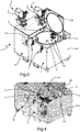
figure 1 is a perspective view of a cart for storing and heating at least one gluing device, according to the invention, in which said cart is in a closed configuration and two gluing devices are arranged on a support plane of said cart; -
figure 2 is a further perspective view of the cart offigure 1 ; -
figure 3 shows the cart offigure 1 in an open configuration for showing a container, arranged inside said cart and sized to receive said two gluing devices; -
figure 4 shows in detail the container containing said two gluing devices, from which a heating device for heating said container has been removed; -
figures 5A and 5B show a respective perspective view of the container offigure 4 ; -
figure 6 is a side sectional view of the cart offigure 1 in closed configuration, when the gluing devices are arranged inside the container to be subjected to a heating process. - In the various figures similar parts will be indicated with the same numerical references.
- With reference to
figures 1-6 , acart 1 is described for storing and heating at least onegluing device 2. - The
gluing device 2 is not an object of the invention. - However, it is necessary to mention some technical features of the
gluing device 2 to explain the operation of thecart 1, object of the invention, with respect to saidgluing device 2. - With reference to the
gluing device 2, saidgluing device 2 comprises areceptacle 21 containing a quantity of solid glue, heating means 22 to heat said amount of glue, anelectric connector 23, as well as a roller (not shown) to apply the glue onto a workpiece, such as a wooden panel. - In the embodiment which is described, the
receptacle 21 of saidgluing device 2 has an opening closed by a door. - The opening of the door allows the insertion of an amount of glue inside said
receptacle 21. - The insertion of the glue inside the
receptacle 21 of thegluing device 2 can be a manual or automated operation. - The shape of said
receptacle 21 is preferably conical, to ease the flow of the glue (once the glue has reached a liquid state) downwards, i.e. towards the roller. - Said gluing
device 2 has a substantially vertical development body, in which saidreceptacle 21 is arranged in the upper part of said body, and said roller is arranged in the lower part of said body. - Said heating means 22 are arranged inside said gluing
device 2 in such a way that, in use, the amount of glue contained in thereceptacle 21 is heated, causing the passage of said amount of glue from a solid state to a liquid state. - As shown in
figure 3 , said heating means 22 are connected to saidelectric connector 23. - In the embodiment which is described, said heating means 22 are electric heating means.
- In particular, in the embodiment that is described, said heating means 22 can comprise at least one electric cable for flowing an electric current, in which said at least one electric cable is connected to said
electric connector 23. - However, said heating means 22 can be induction heating means, without departing from the scope of the invention.
- With reference to the
cart 1, saidcart 1 comprises a supportingunit 10 for supporting said at least onegluing device 2, when it is not necessary to heat an amount of glue contained in thegluing device 2, and a storage andheating unit 11, to preserve saidgluing device 2 and to heat the amount of glue contained therein. - Said storage and
heating unit 11 can be connected or connectable to said supportingunit 10 or arranged next to said supportingunit 10. - In the embodiment that is described, said supporting
unit 10 and said storage andheating unit 11 are separated, as indicated by the solid line infigures 1, 2 and4 , and arranged side-by-side. - With reference to the supporting
unit 10, said supportingunit 10 comprises a supportingplane 101 to support said at least onegluing device 2. - In particular, said supporting
plane 101 is equipped with at least one seat (not shown in the figures), for housing the roller of arespective gluing device 2, wherein a portion of said roller projects from abase 20 of saidgluing device 2. - Furthermore, said supporting
plane 101 is equipped with at least one blockingelement 102, close to said at least one seat, to block saidbase 20 to said supportingplane 101. - With reference to the storage and
heating unit 11, said storage andheating unit 11 comprises a container 3 (arranged inside said storage and heating unit 11), designed to house or contain said at least onegluing device 2 and to supply saidgluing device 2. - In particular, said
container 3 is arranged within a compartment 110 (open at the top) present in said storage andheating unit 11. - With particular reference to said
container 3, saidcontainer 3 has anopening 3A for inserting and extracting said at least onegluing device 2 into/from saidcontainer 3. - In the embodiment that is described, said
container 3 is sized to contain twogluing devices 2. - However, said
container 3 can be sized to receive any number ofgluing devices 2. - For example, said
container 3 can be sized to receive asingle gluing device 2 or a number ofgluing devices 2 greater than two. - Furthermore, in the embodiment which is described, said
container 3 has a cylindrical section. - However, said
container 3 can have any section, without departing from the scope of the invention. - Furthermore, the
opening 3A of saidcontainer 3 is closed by alid 3B. - In the embodiment that is described, said
lid 3B is constrained to aframe 100 of thecart 1 by means of one or more hinges 4 (in the embodiment which is described, thelid 3B is constrained to the frame by two hinges 4). - In particular, in the embodiment which is described, said
lid 3B is sized not only to close theopening 3A of thecontainer 3, but also the opening of the compartment 110 (in which saidcontainer 3 is arranged). - However, it is not necessary that said
lid 3B be sized to close the opening of saidcompartment 110, but it is sufficient that it closes theopening 3A of thecontainer 3. - Furthermore, said
frame 100 is equipped with one or more blocking means 5, for blocking saidlid 3B to the frame itself, so that saidcontainer 3 is hermetically isolated from the external environment to avoid that an amount of air enters in the container. - In other words, any exchange of air between the inside of the container and the external environment is avoided.
- Said blocking means 5 comprise at least one blocking hook.
- In the embodiment that is described, said blocking means 5 comprise two locking hooks.
- Advantageously, said
container 3 can be thermally insulated from the external environment. - Furthermore, said
container 3 comprises a power supply unit for supplying said gluingdevice 2, in which said power supply unit is connected or connectable to a power supply network (not shown), so as to cause the heating of the amount of glue contained in the gluing device and the passage of said amount of glue from a solid state to a liquid state. - Said power supply unit comprises respective first power supply means, which can be coupled to a respective
electric connector 23 of each gluingdevice 2. - Said first power supply means comprise a respective first electrical
power supply connector 103, which can be coupled to a respectiveelectric connector 23 of each gluingdevice 2, so that, in use, the respective heating means 2 of thegluing devices 2 are powered. - In particular, each first electrical
power supply connector 103 is shaped to form a shape coupling with a respectiveelectric connector 23 of each gluing device. - The
container 3 has a first surface orinternal surface 31 and a second surface orexternal surface 32. - In the embodiment that is described, each first electrical
power supply connector 103 is arranged on saidinternal surface 31. - However, each electrical
power supply connector 103 can be arranged on theinternal surface 31 of saidlid 3B, without departing from the invention. - A supporting element 312 is arranged inside said
container 3 and connected to saidinternal surface 31, wherein said supporting element 312 is provided with a respective seat (not shown) for receiving the roller of arespective gluing device 2, to block therespective gluing device 2 on said supporting element 312. - When the
gluing device 2 is inserted inside thecontainer 3 of thecart 1, said gluingdevice 2 is perpendicular or substantially perpendicular to said supporting element 312. - In the embodiment which is described, said
container 3 comprises aheating device 30 for heating said container (i.e., the internal volume of said container) and consequently also thegluing device 2, wherein saidheating device 30 is arranged inside of saidcontainer 3, and said power supply unit also supply saidheating device 30. - However, the presence of said
heating device 30 inside thecontainer 3 is not necessary. - In fact, said
heating device 30 can be positioned if necessary inside saidcontainer 3. - In particular, said power supply unit comprises second supply means for supply said
heating device 30. - Said second power supply means comprise a second electrical
power supply connector 104. - In the embodiment that is described, said second power supply means are arranged inside said
container 3, in particular on said supporting element 312. - However, said second power supply means can be arranged on the
internal surface 31 of saidlid 3B or in general on saidlid 3B, without departing from the invention. - In particular, in the embodiment which is described, said
heating device 30 is a resistor. - Advantageously, said
cart 1 comprises an inertgas delivery device 6, for delivering said at least one inert gas inside saidcontainer 3 to avoid the glue contained in the gluing devices being subjected to a curing process. - In the embodiment which is described, said delivery device is a dry air delivery device.
- By dry air is meant air with a relative humidity percentage lower than 30%, preferably lower than 18%, even more preferably lower than 10%.
- In the embodiment which is described, said dry air delivering device is arranged outside said
container 3. - In particular, said dry
air delivering device 6 has at least one portion in contact with theexternal surface 32 of thecontainer 3. - However, said dry
air delivering device 6 can be arranged inside thecontainer 3, without departing from the scope of the invention. - Alternatively, or in combination with said dry
air delivery device 6, saidcart 1 can comprise a depression generation device (not shown) for generating a depression inside saidcontainer 3, such as for example a vacuum pump. - In case of said
cart 1 comprises both a depression generation device and a dry air delivering device, it is desirable that first a vacuum condition is generated inside thecontainer 3 and then a quantity of dry air is introduced inside thecontainer 3. - Furthermore, said
cart 1 is equipped with movement means to be moved by an operator. - For example, said movement means can comprise a plurality of wheels.
- However, it is not necessary that said
cart 1 is equipped with said movement means (intended as the aforementioned wheels), but can be moved by external devices, such as for example a forklift or other devices equipped with wheels. - The operation of
cart 1 is described below. - Once one or
more gluing devices 2 are inserted (manually or automatically) inside saidcontainer 3, each gluingdevice 2 is arranged on the supporting element 312 (in which a respective seat of said supporting element houses the roller of a respective gluing device 2) and connected to a respective first electricalpower supply connector 103. - Subsequently, a vacuum condition is generated inside said
container 3, to remove the air contained therein and/or an amount of dry air is introduced inside saidcontainer 3 to avoid that the amount of glue contained inside each gluingdevice 2 undergoes a curing process. - At this point, the operator can manually, through a button on a
control panel 121, or remotely, through a mobile electronic device, such as a smartphone, a tablet or a computer, allow the passage of an electric current from the power supply unit towards said heating means 22 and/or towards saidheating device 30, for heating the amount of glue in each gluingdevice 2 until said amount of glue reaches its own melting temperature. - The
control panel 121 is arranged on said storage andheating unit 11. - By means of said
control panel 121 it is possible to activate the depression generation device to create a vacuum condition inside thecontainer 3, and/or to activate the dryair delivery device 6 to introduce an amount of dry air inside of thecontainer 3. - Since each gluing
device 2, although not shown in the figures, comprises a first pneumatic cylinder for opening/closing a shutter in order to allow/prevent the passage of an amount of glue from thereceptacle 21 to the roller, and a second pneumatic cylinder, for opening/closing a dispenser, in order to adjust the amount of glue that goes from thereceptacle 21 to the roller, by means of thecontrol panel 121 it is possible to control the opening/closing of said shutter, and the opening/closing of said dispenser. - Furthermore, the
control panel 121 comprises display means 120 (for example comprising a display), for displaying the temperature value and/or the humidity value inside thecontainer 3, in which said values are respectively detected by a temperature sensor and a humidity sensor arranged inside the container. - Due to the electrical connection between each
electric connector 23 and the respective first electricalpower supply connector 103, an electric current flows into the respective electric heating means 22 of each gluingdevice 2, causing the heating of the amount of glue that is in eachreceptacle 21 of each gluingdevice 2. - Each amount of glue is subjected to a heating process and passes from a solid state to a liquid state, so as to be ready to be applied on a side surface of the panel to be machined, by means of the respective roller.
- Once each amount of glue has reached the melting temperature, the
container 3 is opened and each gluingdevice 2 is extracted, manually or automatically, and made available for further machining by the edge-banding machine. - The present invention also refers to a method for heating an amount of glue contained in one or
more gluing devices 2, wherein each gluingdevice 2 is of the type comprising arespective receptacle 21, containing a quantity of solid glue, respective heating means 22, to heat said amount of glue, and a respectiveelectric connector 23. - Said method comprises the following steps:
- A) providing a
cart 1 described above; - B) opening said
container 3 of saidcart 1, - C) inserting one or
more gluing devices 2 inside saidcontainer 3 of saidcart 1; - D) supplying the respective heating means 22 of said
gluing devices 2 and/or saidheating device 30, causing the heating of the amount of glue contained in each gluingdevice 2. - Said method can comprise before step D, the step of closing the
container 3. - Furthermore, when the
container 3 is closed, before step D, said method can further comprise the following step(s): - creating a depression inside said
container 3 and/or introducing a quantity of inert gas (such as dry air) into saidcontainer 3. - In other words, it is not necessary to close the
container 3 during the heating of the glue. - However, if before heating the glue, it is necessary creating depression and/or introducing an amount of inert gas inside of the
container 3, saidcontainer 3 has to be closed. - Advantageously, as already mentioned, the cart object of the present invention has a simple structure from the mechanical and electrical point of view.
- The present invention has been described for illustrative but not limitative purposes, according to its preferred embodiments, but it is to be understood that modifications and/or changes can be introduced by those skilled in the art without departing from the relevant scope as defined in the enclosed claims.
Claims (12)
- Cart (1) for storing and heating at least one gluing device (2), wherein said gluing device (2) is of the type comprising a receptacle (21) containing a quantity of solid glue, heating means (22) for heating said quantity of glue, said cart (1) comprising:- a container (3) for containing said at least one gluing device (2),- a power supply unit (103,104) for supplying power to said gluing device (2) and/or to a heating device (30) for heating the internal volume of said container (3), to be positioned in use inside said container (3), wherein said power supply unit is connected or connectable to a power supply network, so that, in use, said heating means (22) and/or said heating device (30) are/are powered, causing heating said quantity of glue contained in said gluing device (2) and changing said quantity of glue from a solid state to a liquid state.
- Cart (1) according to the previous claim, characterized in that said power supply unit (103,104) comprises first power supply means (103) for supplying power to said heating means (22) of said gluing device (2) and/or second power supplying means (104) for supplying power to said heating device (30).
- Cart (1) according to the claim 1 or 2, characterized in that said heating device (30) (30) is a resistor.
- Cart (1) according to claim 1 or 2, characterized in that said first power supplying means (103) comprise a power electric connector (103) couplable to an electric connector (23) of said gluing device (2), wherein said electric connector (23) is connected to said heating means (22).
- Cart (1) according to any one of the previous claims, characterized in that said container (3) has an opening (3A) to allow the insertion and extraction of said gluing device (2) in/from said container (3), and in that said cart (1) comprises a lid (3B) to close said opening (3A).
- Cart (1) according to the previous claim, characterized in that said cart (1) comprises a frame (100) and in that said cart (1) is provided with blocking means (5) for blocking said lid (3B) to the frame (100) itself, so as to prevent a quantity of air enters the container (3).
- Cart (1) according to any one of the previous claims, characterized in that said container (3) is thermally isolated from the external environment.
- Cart (1) according to any one of the previous claims, characterized in that said cart (1) comprises a storage and heating unit (11), inside which said container (3) is arranged, and a support unit (10) to support said at least one gluing device (2).
- Cart (1) according to any one of the previous claims, characterized in that said cart (1) comprises an inert gas supplying device (6) for supplying at least one inert gas inside said container (3) and/or a depression generating device for generating a depression inside said container (3).
- Method for heating a quantity of glue contained in at least one gluing device (2), wherein said gluing device (2) is of the type comprising a container (21) containing a quantity of solid glue, heating means (22) for heating said amount of glue, wherein said method comprises the following steps:A) providing a cart (1) according to any one of claims 1-9;B) opening said container (3) of said cart (1);C) inserting said gluing device (2) inside said container (3) of said cart (1);D) supplying power to said heating means (22) and/or to a heating device (30), causing heating the quantity of glue contained in said gluing device (2).
- Method according to the previous claim, characterized in that, before step D, said method comprises the step of closing said container (3).
- Method according to the previous claim, characterized in that, when said container (3) is closed, said method further comprises the following step(s):- create a depression inside said container (3) and/or introduce a quantity of inert gas inside said container (3).
Applications Claiming Priority (1)
| Application Number | Priority Date | Filing Date | Title |
|---|---|---|---|
| IT102020000013366A IT202000013366A1 (en) | 2020-06-05 | 2020-06-05 | TROLLEY FOR STORING AND HEATING AT LEAST ONE GLUING DEVICE |
Publications (1)
| Publication Number | Publication Date |
|---|---|
| EP3919183A1 true EP3919183A1 (en) | 2021-12-08 |
Family
ID=72179069
Family Applications (1)
| Application Number | Title | Priority Date | Filing Date |
|---|---|---|---|
| EP21177638.0A Pending EP3919183A1 (en) | 2020-06-05 | 2021-06-03 | Cart for storing and heating at least one gluing device |
Country Status (2)
| Country | Link |
|---|---|
| EP (1) | EP3919183A1 (en) |
| IT (1) | IT202000013366A1 (en) |
Cited By (2)
| Publication number | Priority date | Publication date | Assignee | Title |
|---|---|---|---|---|
| CN114347197A (en) * | 2022-01-17 | 2022-04-15 | 广州市豪田机械设备有限公司 | Multifunctional glue coating pot device for edge bonding machine process |
| EP3995275A1 (en) * | 2020-11-10 | 2022-05-11 | IMA Schelling Deutschland GmbH | Adhesive applicator device, edge glueing machine and method for operating the same |
Citations (3)
| Publication number | Priority date | Publication date | Assignee | Title |
|---|---|---|---|---|
| EP1057535A1 (en) * | 1999-06-04 | 2000-12-06 | Robatech AG | Device for applying in liquid state, a material onto a surface, and utilisation of this device |
| US20070045289A1 (en) * | 2005-08-02 | 2007-03-01 | John Kott | Portable spray system |
| US20180031163A1 (en) * | 2013-09-18 | 2018-02-01 | Nordson Corporation | Bulk adhesive transfer devices, knife gate valve devices, and related systems and methods |
-
2020
- 2020-06-05 IT IT102020000013366A patent/IT202000013366A1/en unknown
-
2021
- 2021-06-03 EP EP21177638.0A patent/EP3919183A1/en active Pending
Patent Citations (3)
| Publication number | Priority date | Publication date | Assignee | Title |
|---|---|---|---|---|
| EP1057535A1 (en) * | 1999-06-04 | 2000-12-06 | Robatech AG | Device for applying in liquid state, a material onto a surface, and utilisation of this device |
| US20070045289A1 (en) * | 2005-08-02 | 2007-03-01 | John Kott | Portable spray system |
| US20180031163A1 (en) * | 2013-09-18 | 2018-02-01 | Nordson Corporation | Bulk adhesive transfer devices, knife gate valve devices, and related systems and methods |
Cited By (2)
| Publication number | Priority date | Publication date | Assignee | Title |
|---|---|---|---|---|
| EP3995275A1 (en) * | 2020-11-10 | 2022-05-11 | IMA Schelling Deutschland GmbH | Adhesive applicator device, edge glueing machine and method for operating the same |
| CN114347197A (en) * | 2022-01-17 | 2022-04-15 | 广州市豪田机械设备有限公司 | Multifunctional glue coating pot device for edge bonding machine process |
Also Published As
| Publication number | Publication date |
|---|---|
| IT202000013366A1 (en) | 2021-12-05 |
Similar Documents
| Publication | Publication Date | Title |
|---|---|---|
| CN109624517A (en) | A kind of self-service customization machine of ready-made clothes pattern, print system and Method of printing | |
| US20190217597A1 (en) | Lamination System, Facility Including Such a Lamination System and Lamination Method Implemented Using Such a Lamination System | |
| IT202000013366A1 (en) | TROLLEY FOR STORING AND HEATING AT LEAST ONE GLUING DEVICE | |
| EP3919184A1 (en) | Improved cart for storing and heating at least one gluing device | |
| JP3521296B2 (en) | Ink injection method and ink injection apparatus | |
| CN108453683A (en) | Portable integrated electronic welding tool case | |
| CN210592756U (en) | Filling production line | |
| CN219882491U (en) | Lifting repairing frame | |
| CN205525659U (en) | Automatic order dosing unit | |
| CN105857660B (en) | Enter bag mechanism and its enters a bag technique | |
| CN216797452U (en) | Efficient rotary wall-mounted seasoning box | |
| CN210592545U (en) | Filling device | |
| CN208963100U (en) | A kind of welding machine trolley | |
| CN201155838Y (en) | Indoor cabinet air-conditioner remote controller receptacle | |
| CN208737582U (en) | A kind of new type auto vending machine | |
| CN217477673U (en) | Movable tender lotus seed processing device | |
| CN207766112U (en) | Threephase asynchronous machine multirobot collaborative assembly system based on MES system | |
| CN217161410U (en) | File cabinet with adjustable storage space | |
| CN206228009U (en) | A kind of cutter stock shelf | |
| CN220672410U (en) | Capacitor soaking assembly | |
| CN217865194U (en) | Preparation row of packing in bags bubble heat seal device | |
| CN110921171A (en) | Logistics storage method | |
| CN213505240U (en) | Double-top-pressure rubber coating machine | |
| CN224205371U (en) | Display device for industrial control cabinet | |
| CN209449986U (en) | A kind of aviation case being easy to implement box equipment wiring |
Legal Events
| Date | Code | Title | Description |
|---|---|---|---|
| PUAI | Public reference made under article 153(3) epc to a published international application that has entered the european phase |
Free format text: ORIGINAL CODE: 0009012 |
|
| STAA | Information on the status of an ep patent application or granted ep patent |
Free format text: STATUS: THE APPLICATION HAS BEEN PUBLISHED |
|
| AK | Designated contracting states |
Kind code of ref document: A1 Designated state(s): AL AT BE BG CH CY CZ DE DK EE ES FI FR GB GR HR HU IE IS IT LI LT LU LV MC MK MT NL NO PL PT RO RS SE SI SK SM TR |
|
| B565 | Issuance of search results under rule 164(2) epc |
Effective date: 20211103 |
|
| STAA | Information on the status of an ep patent application or granted ep patent |
Free format text: STATUS: REQUEST FOR EXAMINATION WAS MADE |
|
| 17P | Request for examination filed |
Effective date: 20220310 |
|
| RBV | Designated contracting states (corrected) |
Designated state(s): AL AT BE BG CH CY CZ DE DK EE ES FI FR GB GR HR HU IE IS IT LI LT LU LV MC MK MT NL NO PL PT RO RS SE SI SK SM TR |
|
| STAA | Information on the status of an ep patent application or granted ep patent |
Free format text: STATUS: EXAMINATION IS IN PROGRESS |
|
| 17Q | First examination report despatched |
Effective date: 20240419 |