EP3918347B1 - Current transducer with magnetic field detector module - Google Patents
Current transducer with magnetic field detector module Download PDFInfo
- Publication number
- EP3918347B1 EP3918347B1 EP20702764.0A EP20702764A EP3918347B1 EP 3918347 B1 EP3918347 B1 EP 3918347B1 EP 20702764 A EP20702764 A EP 20702764A EP 3918347 B1 EP3918347 B1 EP 3918347B1
- Authority
- EP
- European Patent Office
- Prior art keywords
- magnetic field
- magnetic
- circuit board
- core
- detector module
- Prior art date
- Legal status (The legal status is an assumption and is not a legal conclusion. Google has not performed a legal analysis and makes no representation as to the accuracy of the status listed.)
- Active
Links
Images


Classifications
-
- G—PHYSICS
- G01—MEASURING; TESTING
- G01R—MEASURING ELECTRIC VARIABLES; MEASURING MAGNETIC VARIABLES
- G01R1/00—Details of instruments or arrangements of the types included in groups G01R5/00 - G01R13/00 and G01R31/00
- G01R1/02—General constructional details
- G01R1/04—Housings; Supporting members; Arrangements of terminals
-
- G—PHYSICS
- G01—MEASURING; TESTING
- G01R—MEASURING ELECTRIC VARIABLES; MEASURING MAGNETIC VARIABLES
- G01R1/00—Details of instruments or arrangements of the types included in groups G01R5/00 - G01R13/00 and G01R31/00
- G01R1/02—General constructional details
- G01R1/04—Housings; Supporting members; Arrangements of terminals
- G01R1/0408—Test fixtures or contact fields; Connectors or connecting adaptors; Test clips; Test sockets
- G01R1/0416—Connectors, terminals
-
- G—PHYSICS
- G01—MEASURING; TESTING
- G01R—MEASURING ELECTRIC VARIABLES; MEASURING MAGNETIC VARIABLES
- G01R15/00—Details of measuring arrangements of the types provided for in groups G01R17/00 - G01R29/00, G01R33/00 - G01R33/26 or G01R35/00
- G01R15/14—Adaptations providing voltage or current isolation, e.g. for high-voltage or high-current networks
- G01R15/18—Adaptations providing voltage or current isolation, e.g. for high-voltage or high-current networks using inductive devices, e.g. transformers
- G01R15/183—Adaptations providing voltage or current isolation, e.g. for high-voltage or high-current networks using inductive devices, e.g. transformers using transformers with a magnetic core
-
- G—PHYSICS
- G01—MEASURING; TESTING
- G01R—MEASURING ELECTRIC VARIABLES; MEASURING MAGNETIC VARIABLES
- G01R15/00—Details of measuring arrangements of the types provided for in groups G01R17/00 - G01R29/00, G01R33/00 - G01R33/26 or G01R35/00
- G01R15/14—Adaptations providing voltage or current isolation, e.g. for high-voltage or high-current networks
- G01R15/20—Adaptations providing voltage or current isolation, e.g. for high-voltage or high-current networks using galvano-magnetic devices, e.g. Hall-effect devices, i.e. measuring a magnetic field via the interaction between a current and a magnetic field, e.g. magneto resistive or Hall effect devices
- G01R15/202—Adaptations providing voltage or current isolation, e.g. for high-voltage or high-current networks using galvano-magnetic devices, e.g. Hall-effect devices, i.e. measuring a magnetic field via the interaction between a current and a magnetic field, e.g. magneto resistive or Hall effect devices using Hall-effect devices
-
- G—PHYSICS
- G01—MEASURING; TESTING
- G01R—MEASURING ELECTRIC VARIABLES; MEASURING MAGNETIC VARIABLES
- G01R15/00—Details of measuring arrangements of the types provided for in groups G01R17/00 - G01R29/00, G01R33/00 - G01R33/26 or G01R35/00
- G01R15/14—Adaptations providing voltage or current isolation, e.g. for high-voltage or high-current networks
- G01R15/20—Adaptations providing voltage or current isolation, e.g. for high-voltage or high-current networks using galvano-magnetic devices, e.g. Hall-effect devices, i.e. measuring a magnetic field via the interaction between a current and a magnetic field, e.g. magneto resistive or Hall effect devices
- G01R15/207—Constructional details independent of the type of device used
-
- G—PHYSICS
- G01—MEASURING; TESTING
- G01R—MEASURING ELECTRIC VARIABLES; MEASURING MAGNETIC VARIABLES
- G01R19/00—Arrangements for measuring currents or voltages or for indicating presence or sign thereof
- G01R19/0092—Measuring current only
-
- H—ELECTRICITY
- H01—ELECTRIC ELEMENTS
- H01F—MAGNETS; INDUCTANCES; TRANSFORMERS; SELECTION OF MATERIALS FOR THEIR MAGNETIC PROPERTIES
- H01F27/00—Details of transformers or inductances, in general
- H01F27/24—Magnetic cores
-
- H—ELECTRICITY
- H01—ELECTRIC ELEMENTS
- H01F—MAGNETS; INDUCTANCES; TRANSFORMERS; SELECTION OF MATERIALS FOR THEIR MAGNETIC PROPERTIES
- H01F27/00—Details of transformers or inductances, in general
- H01F27/28—Coils; Windings; Conductive connections
-
- H—ELECTRICITY
- H05—ELECTRIC TECHNIQUES NOT OTHERWISE PROVIDED FOR
- H05K—PRINTED CIRCUITS; CASINGS OR CONSTRUCTIONAL DETAILS OF ELECTRIC APPARATUS; MANUFACTURE OF ASSEMBLAGES OF ELECTRICAL COMPONENTS
- H05K1/00—Printed circuits
- H05K1/18—Printed circuits structurally associated with non-printed electric components
- H05K1/181—Printed circuits structurally associated with non-printed electric components associated with surface mounted components
-
- H—ELECTRICITY
- H05—ELECTRIC TECHNIQUES NOT OTHERWISE PROVIDED FOR
- H05K—PRINTED CIRCUITS; CASINGS OR CONSTRUCTIONAL DETAILS OF ELECTRIC APPARATUS; MANUFACTURE OF ASSEMBLAGES OF ELECTRICAL COMPONENTS
- H05K2201/00—Indexing scheme relating to printed circuits covered by H05K1/00
- H05K2201/10—Details of components or other objects attached to or integrated in a printed circuit board
- H05K2201/10007—Types of components
- H05K2201/1003—Non-printed inductor
-
- H—ELECTRICITY
- H05—ELECTRIC TECHNIQUES NOT OTHERWISE PROVIDED FOR
- H05K—PRINTED CIRCUITS; CASINGS OR CONSTRUCTIONAL DETAILS OF ELECTRIC APPARATUS; MANUFACTURE OF ASSEMBLAGES OF ELECTRICAL COMPONENTS
- H05K2201/00—Indexing scheme relating to printed circuits covered by H05K1/00
- H05K2201/10—Details of components or other objects attached to or integrated in a printed circuit board
- H05K2201/10007—Types of components
- H05K2201/10151—Sensor
Definitions
- the present invention relates to an electric current transducer comprising a magnetic core and a magnetic field detector in an air-gap of the magnetic core, for measuring an electrical current flowing in a primary conductor extending through a central passage of the magnetic core.
- Electrical current sensors are used in a large variety of applications for monitoring or controlling electrical devices and system and in many applications there is an important advantage in reducing the manufacturing cost of such components and in particular the cost of assembling the components of the sensor.
- many electrical current transducers for current sensing applications comprise a magnetic core made of a high permeability magnetic material, surrounding a central aperture through which passes a primary conductor carrying the current to be measured.
- the current transducer is mounted on a circuit board, for interconnecting the magnetic field detector signal and power supply contacts to control circuitry of an electrical device, for instance of an electrical motor.
- the primary conductor comprises a rigid conductive bar that is integrated in the current transducer and presents connection ends for connection to a primary conductor connected to the electrical device.
- the primary conductor may typically be a plurality of current transducers and associated primary conductor bars mounted on a circuit board, for instance for connection to a plurality of electrical phases of the electrical device.
- EP2530475A2 discloses a current transducer.
- An object of the invention is to provide an electrical current transducer for mounting on a circuit board, with integrated magnetic field detector and magnetic core for mounting around a primary conductor, which is accurate, reliable and robust, yet compact and cost effective to manufacture, in particular that is easy and cost effective to assemble.
- an electrical current transducer comprising a magnetic core and a magnetic field detector module, the magnetic core and magnetic field detector module each forming a single unit separably mountable around a primary conductor and to a circuit board, the magnetic core having a general U shape comprising an end branch and lateral branches extending the end branch to respective free ends, the magnetic field detector module being positioned between the lateral branches and extending across a whole width of a gap formed between the lateral branches such that the magnetic field detector module contacts opposed inner sides of said lateral branches, said inner sides arranged substantially orthogonally to the circuit board.
- the magnetic field detector module comprises at least one magnetic field sensing cell, a pair of magnetic concentrators arranged in mirror opposition forming a magnetic field gap therebetween, the at least one sensing cell being positioned inside the magnetic field gap, and an insulating body supporting the magnetic concentrators and at least one sensing cell.
- the primary conductor is positioned adjacent a first magnetic side of the circuit board and the magnetic field detector module is mounted on a second side of the circuit board.
- the magnetic field detector module is mounted principally on a first side of the circuit board and the primary conductor is positioned adjacent the magnetic field detector module on said first side of the circuit board.
- the lateral branches of the magnetic core are substantially parallel to each other.
- the lateral branches are substantially orthogonal to the end branch of the magnetic core.
- each magnetic concentrator extends from a core branch end adjacent a respective lateral branch, to a detector end forming a face of the magnetic field gap, a ratio of a surface area Ab of the detector end divided by a surface area Aa of the core branch end being less than 80% ( Ab / Aa ⁇ 80% ), preferably in a range of 50% to 80 % ( 50% ⁇ Ab / Aa ⁇ 80% ).
- each magnetic concentrator extends from a core branch end adjacent a respective lateral branch, to a detector end forming a face of the magnetic field gap, the core branch end being in direct contact with a respective said lateral branch of the magnetic core.
- the direct contact may also include a direct electrical contact, for instance for grounding of the magnetic core whereby the magnetic concentrators may be connected to a terminal for connection to ground.
- the lateral branches of the magnetic core may be coupled, for instance by soldering, to the circuit board provided with a metal layer on the edges of the orifices.
- the conductive interconnection may also serve as a ground connection in an embodiment.
- the at least one sensing cell is in a form of an application specific integrated circuit (ASIC) having terminals for power and signal transmission.
- ASIC application specific integrated circuit
- the ASIC comprises a Hall Effect detector.
- the terminals either form connection terminals for direct connection to the circuit board or are connected to terminals formed from a stamped lead frame and supported within the insulating body.
- the insulating body comprises a polymer material overmolded over the magnetic concentrators and the at least one sensing cell.
- the insulating body does not cover core branch ends of the pair of opposed magnetic concentrators such that the core branch ends may be in direct contact with inner sides of the lateral branches of the magnetic core.
- the transducer comprises two said sensing cells adjacently mounted in the magnetic field gap.
- an electrical current transducer 2 comprises a magnetic core 6, a magnetic field detector module 8, a circuit board 10 and a primary conductor 4 for carrying a primary current to be measured by the electrical current transducer 2.
- the magnetic core 6 has a general U shape comprising an end branch 14a and lateral branches 14b extending from ends of the end branch 14a to respective free ends 14c.
- the lateral branches 14b are substantially parallel to each other.
- the lateral branches are substantially orthogonal to the end branch 14a.
- the magnetic field detector module 8 is positioned between the lateral branches 14b and extends across the whole width of a gap formed between the lateral branches 14b.
- the magnetic core 6 and magnetic field detector module 8 surround a passage 12 through which the primary conductor 4 extends.
- the primary conductor 4 may be in the form of a rigid bar shaped conductor.
- the primary conductor 4 may comprise other configurations for instance in the form of a dielectric material supporting one or more conductors thereon, for instance in a form of a circuit board having a primary conductor printed or otherwise positioned thereon.
- the primary conductor bar has a rectangular shape, other profiles such as square, polygonal, elliptical, circular and irregular bar shapes may be provided.
- the primary conductor bar 4 may have a substantially constant cross section over the length of the transducer or may have a non-constant cross section, for instance a smaller width along a section extending through the passage 12 formed by the magnetic core 6.
- Ends of the conductor bus bar may have various configurations for interconnection to a primary conductor supplying the current to be measured.
- the primary conductor bar may also be interconnected by soldering, welding, clamping or other means to conductive tracks formed on the circuit board 10 or to connection ends of a primary conductor.
- the free ends 14c of the lateral branches 14b of the magnetic core 6 may be inserted through orifices 30 extending through the circuit board 10 between a first side 28a and a second side 28b of the circuit board.
- the primary conductor 4 is positioned adjacent the first side of the circuit board 10, and the magnetic field detector module 8 is mounted on the second side 28b of the circuit board 10.
- the free ends 14c of the lateral branches 14b of the magnetic core 6 extend through the orifices 30 to a height H from the second side 28b, the height being sufficient for positioning the magnetic field detector module 8 between the lateral branches 14b.
- the magnetic field detector module comprises connection terminals 18 that interconnect to conductive circuit traces formed on the circuit board 10 the circuit traces are interconnected to control electronics of an electrical device connected to the primary conductor 4 in which the current to be measured flows.
- the primary conductor 4 is positioned facing the first side 28a of the circuit board 10, and the magnetic field detector module 8 is positioned principally on the first side 28a.
- the magnetic field detector module is mounted on the first side 28a, the magnetic core 6 being mounted over both the primary conductor 4 and the magnetic field detector module 6 on the first side 28a of the circuit board.
- the circuit board 10 comprises an orifice 32 for the magnetic field detector module inserted through the circuit board from the second side 28b.
- the magnetic core 6 is made of a soft magnetic material as per se well known in the field of magnetic cores for current transducers, and forms a path of low magnetic resistance to capture the magnetic flux generated by the primary current flowing in the primary conductor 4.
- the magnetic field detector module 8 is magnetically coupled to the lateral branches of the magnetic core.
- the magnetic field detector module 8 comprises at least one magnetic field sensing cell 16, a pair of magnetic concentrators 22 arranged in mirror opposition forming a magnetic field gap 26 therebetween in which the one or more sensing cells 16 is/are positioned, and an insulating body 20 supporting the magnetic concentrators 22 and sensing cell(s) 16.
- Each magnetic concentrator extends from a core branch end 24a adjacent respective lateral branches 14b, either in direct contact with the lateral branches 14b or in close proximity thereto, to a detector end 24b forming a face of the magnetic field gap 26.
- Magnetic concentrators 22 thus concentrate the magnetic flux circulating in the U shaped magnetic core through the magnetic field gap 26.
- the magnetic concentrators may be made of a ferrite material with a high magnetic permeability the geometry of the ferrite material being selected such that the flux density inside the ferrite is less than a half the saturation flux density of the material. This allows the ferrite properties to be preserved up to a temperature exceeding half of its Curie temperature. In an advantageous embodiment, the ferrite properties are preserved up to a temperature of at least 120 degrees centigrade preferably up to 125 degrees centigrade.
- the magnetic concentrators 22 may be formed of an iron silicon material FeSi that may be formed of stamped metal sheets, a plurality being stacked to form a laminated structure. Laminated structures are per se well known in the art of magnetic armatures.
- the core branch end 24a has a surface area facing the lateral branch that is greater than a surface area of the detector end 24b facing the magnetic field gap. This allows the magnetic field detector module 8 to concentrate magnetic flux through the sensing cell(s) 16 positioned in the magnetic field gap 26 while at the same time reducing the risk of saturation in the magnetic core, and in particular at the interfaces between the magnetic core 6 and the magnetic concentrators 22.
- the ratio of the surface area A b of the detector end face 24b over the surface area A a of the core branch interface 24a is preferably less than 80% ( A b / A a ⁇ 80% ), preferably in a range of 50 to 80 % ( 50% ⁇ A b / A a ⁇ 80% ).
- the sensing cell 16 may advantageously be in a form of an application specific integrated circuit (ASIC) having terminals 17 for connection to conductive circuit traces on the circuit board 10 for power and signal transmission.
- ASIC application specific integrated circuit
- the ASIC may comprise a Hall effect detector, however the sensing cell may comprise other per se well known magnetic field detectors.
- the terminals 17 either form connection terminals for direct connection to the circuit board 10 or may be connected to terminals 18 supported in an insulating body 20 of the magnetic field detector module 8.
- the terminals 18 may advantageously be formed from a stamped lead frame and supported within the insulating body 20.
- two sensing cells 16 may be adjacently mounted in the magnetic field gap. This allows to provide a redundant magnetic field detector for applications requiring increased safety or reliability.
- the sensing cells may advantageously be identical and mounted in mirror image symmetry.
- the two sensing cells may also be connected to control electronics in a manner to sum or to average the output signal of the sensing cells.
- the insulating body may for instance comprise a polymer material overmolded over the magnetic concentrators 22 and the sensing cell 16.
- the insulating body 20 may also be formed of one or more housing parts that are assembled and fixed around the magnetic concentrator and sensing cell(s).
- the insulating body 20 does not cover the core branch ends 24a of the pair of opposed magnetic concentrators 22 such that the core branch ends may be in direct contact with the inner sides of the lateral branches 14b of the magnetic core 6.
- the small magnetic field gap formed therebetween thus improves magnetic flux conduction between the magnetic core and the magnetic field concentrators.
- this direct contact may also provide electrical interconnection between the magnetic core 6 and the magnetic concentrators 22 to provide a ground connection for the magnetic field concentrators 22 by interconnecting the magnetic core 6 to conductive circuit traces on the circuit board connected to electrical ground.
- the lateral branches 14b may advantageously be inserted through the orifices 30 and soldered, welded, bonded by adhesive or fixed by mechanical means to the circuit board.
- conductive pads or circuit traces lining the orifices 30 may be provided for mechanical and optionally electric coupling of the magnet core 6 to the circuit board 10.
- other interconnection means would be possible within the scope of the invention, for instance by providing elastic contacts on the circuit board for clamping the lateral branches of the magnetic core or other mechanical fixing means such as with screws or rivets.
- the magnetic field detector module comprising magnetic field concentrators and a magnetic sensing cell held in an insulating body as a separate and single unit mountable between lateral branches of a simple U shaped magnetic core, allows easy assembly and direct integration of the current transducer on a circuit board and around a primary conductor bar, as well as a compact configuration.
- the separately formed magnetic field detector module 8 increases flexibility of the configuration, in particular for placing the primary conductor bar on a same side of the circuit board or on an opposite side of the circuit board with respect to the magnetic field detector module.
- the formation of the magnetic field gap between magnetic field concentrators within which the sensing cell 16 is positioned, held in an insulating body, in particular an insulating body 20 that may be overmolded over the aforesaid components, ensures an accurate and stable magnetic field gap while allowing great flexibility in assembly around a primary conductor bar in a cost effective manner.
- the invention thus facilitates assembly and increases mounting possibilities while ensuring accurate and stable measurement in a robust configuration.
Landscapes
- Physics & Mathematics (AREA)
- General Physics & Mathematics (AREA)
- Engineering & Computer Science (AREA)
- Power Engineering (AREA)
- Microelectronics & Electronic Packaging (AREA)
- Measuring Instrument Details And Bridges, And Automatic Balancing Devices (AREA)
Description
- The present invention relates to an electric current transducer comprising a magnetic core and a magnetic field detector in an air-gap of the magnetic core, for measuring an electrical current flowing in a primary conductor extending through a central passage of the magnetic core.
- Electrical current sensors are used in a large variety of applications for monitoring or controlling electrical devices and system and in many applications there is an important advantage in reducing the manufacturing cost of such components and in particular the cost of assembling the components of the sensor.
- Although certain current transducers are provided without a magnetic core for cost and/or size reasons, this generally reduces reliability and/or sensitivity and/or accuracy and/or operating range of the transducer compared to one provided with a magnetic core surrounding the primary conductor. Therefore, many electrical current transducers for current sensing applications comprise a magnetic core made of a high permeability magnetic material, surrounding a central aperture through which passes a primary conductor carrying the current to be measured. In many applications, the current transducer is mounted on a circuit board, for interconnecting the magnetic field detector signal and power supply contacts to control circuitry of an electrical device, for instance of an electrical motor. Often, especially for high power applications, the primary conductor comprises a rigid conductive bar that is integrated in the current transducer and presents connection ends for connection to a primary conductor connected to the electrical device. There may typically be a plurality of current transducers and associated primary conductor bars mounted on a circuit board, for instance for connection to a plurality of electrical phases of the electrical device.
- The provision of a separately manufactured transducer as a single component for mounting on a circuit board however is often not optimal in terms of size and weight.
- The document
EP2530475A2 discloses a current transducer. - An object of the invention is to provide an electrical current transducer for mounting on a circuit board, with integrated magnetic field detector and magnetic core for mounting around a primary conductor, which is accurate, reliable and robust, yet compact and cost effective to manufacture, in particular that is easy and cost effective to assemble.
- It is advantageous to provide an electrical current transducer that has a large operating range.
- Objects of the invention have been achieved by providing a current transducer according to claim 1 and a method of assembling a current transducer according to claim 13.
- Disclosed herein is an electrical current transducer comprising a magnetic core and a magnetic field detector module, the magnetic core and magnetic field detector module each forming a single unit separably mountable around a primary conductor and to a circuit board, the magnetic core having a general U shape comprising an end branch and lateral branches extending the end branch to respective free ends, the magnetic field detector module being positioned between the lateral branches and extending across a whole width of a gap formed between the lateral branches such that the magnetic field detector module contacts opposed inner sides of said lateral branches, said inner sides arranged substantially orthogonally to the circuit board. The magnetic field detector module comprises at least one magnetic field sensing cell, a pair of magnetic concentrators arranged in mirror opposition forming a magnetic field gap therebetween, the at least one sensing cell being positioned inside the magnetic field gap, and an insulating body supporting the magnetic concentrators and at least one sensing cell.
- Also disclosed herein is a method of assembling the electrical current transducer comprising: (a) mounting the magnetic field detector module on the circuit board; (b) mounting the magnetic core around the primary conductor and inserting the free ends of the magnetic core through the orifices (30) of the circuit board, whereby the magnetic field detector module is positioned between the lateral branches and extends across a whole width of a gap formed between the lateral branches such that the magnetic field detector module contacts opposed inner sides of said lateral branches, said inner sides arranged substantially orthogonally to the circuit board.
- In an embodiment, the primary conductor is positioned adjacent a first magnetic side of the circuit board and the magnetic field detector module is mounted on a second side of the circuit board.
- In an embodiment, the magnetic field detector module is mounted principally on a first side of the circuit board and the primary conductor is positioned adjacent the magnetic field detector module on said first side of the circuit board.
- In an advantageous embodiment, the lateral branches of the magnetic core are substantially parallel to each other.
- In an advantageous embodiment, the lateral branches are substantially orthogonal to the end branch of the magnetic core.
- In an advantageous embodiment, each magnetic concentrator extends from a core branch end adjacent a respective lateral branch, to a detector end forming a face of the magnetic field gap, a ratio of a surface area Ab of the detector end divided by a surface area Aa of the core branch end being less than 80% (Ab / Aa < 80% ), preferably in a range of 50% to 80 % ( 50% < Ab / Aa < 80% ).
- In an advantageous embodiment, each magnetic concentrator extends from a core branch end adjacent a respective lateral branch, to a detector end forming a face of the magnetic field gap, the core branch end being in direct contact with a respective said lateral branch of the magnetic core.
- The direct contact may also include a direct electrical contact, for instance for grounding of the magnetic core whereby the magnetic concentrators may be connected to a terminal for connection to ground.
- In an embodiment, the lateral branches of the magnetic core are inserted through orifices in the circuit board.
- In an embodiment, the lateral branches of the magnetic core may be coupled, for instance by soldering, to the circuit board provided with a metal layer on the edges of the orifices. The conductive interconnection may also serve as a ground connection in an embodiment.
- In an advantageous embodiment, the at least one sensing cell is in a form of an application specific integrated circuit (ASIC) having terminals for power and signal transmission.
- In an advantageous embodiment, the ASIC comprises a Hall Effect detector.
- In embodiments, the terminals either form connection terminals for direct connection to the circuit board or are connected to terminals formed from a stamped lead frame and supported within the insulating body.
- In an advantageous embodiment, the insulating body comprises a polymer material overmolded over the magnetic concentrators and the at least one sensing cell.
- In an advantageous embodiment, the insulating body does not cover core branch ends of the pair of opposed magnetic concentrators such that the core branch ends may be in direct contact with inner sides of the lateral branches of the magnetic core.
- In an embodiment, the transducer comprises two said sensing cells adjacently mounted in the magnetic field gap.
- Further objects and advantageous features of the invention will be apparent from the claims, from the detailed description, and annexed drawings, in which:
-
Figure 1a is a perspective view of an electrical current transducer according to an embodiment of the invention; -
Figure 1b is a perspective partial cross sectional view of the electrical current transducer offigure 1a ; -
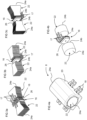
Figure 2a is a perspective view of a magnetic field detector module of an electrical current transducer according to an embodiment of the invention; -
Figure 2b is a perspective partial cross sectional view of the magnetic field detector module offigure 2a ; -
Figures 3a to 3c illustrate in perspective magnetic concentrators and sensing cells of current transducers according to embodiments of the invention; -
Figure 4a is a perspective view of a magnetic field detector module of an electrical current transducer according to another embodiment of the invention; -
Figure 4b is a perspective view of magnetic concentrators and sensing cell of the magnetic field detector module offigure 4a ; -
Figures 5a and 5b illustrate in perspective an electrical current transducer according to a second embodiment of the invention; -
Figures 6a and 6b illustrate in perspective an electrical current transducer according to a third embodiment of the invention; - Referring to the figures, an electrical current transducer 2 according to embodiments of the invention comprises a
magnetic core 6, a magneticfield detector module 8, acircuit board 10 and aprimary conductor 4 for carrying a primary current to be measured by the electrical current transducer 2. - The
magnetic core 6 has a general U shape comprising anend branch 14a andlateral branches 14b extending from ends of theend branch 14a to respectivefree ends 14c. In a preferred embodiment, thelateral branches 14b are substantially parallel to each other. In a preferred embodiment, the lateral branches are substantially orthogonal to theend branch 14a. - The magnetic
field detector module 8 is positioned between thelateral branches 14b and extends across the whole width of a gap formed between thelateral branches 14b. Themagnetic core 6 and magneticfield detector module 8 surround apassage 12 through which theprimary conductor 4 extends. - The
primary conductor 4 may be in the form of a rigid bar shaped conductor. In variants, theprimary conductor 4 may comprise other configurations for instance in the form of a dielectric material supporting one or more conductors thereon, for instance in a form of a circuit board having a primary conductor printed or otherwise positioned thereon. While in the illustrated embodiment the primary conductor bar has a rectangular shape, other profiles such as square, polygonal, elliptical, circular and irregular bar shapes may be provided. Theprimary conductor bar 4 may have a substantially constant cross section over the length of the transducer or may have a non-constant cross section, for instance a smaller width along a section extending through thepassage 12 formed by themagnetic core 6. - Ends of the conductor bus bar (not shown) may have various configurations for interconnection to a primary conductor supplying the current to be measured. The primary conductor bar may also be interconnected by soldering, welding, clamping or other means to conductive tracks formed on the
circuit board 10 or to connection ends of a primary conductor. - The
free ends 14c of thelateral branches 14b of themagnetic core 6 may be inserted throughorifices 30 extending through thecircuit board 10 between afirst side 28a and asecond side 28b of the circuit board. - In a first embodiment as illustrated in
figure 1 , theprimary conductor 4 is positioned adjacent the first side of thecircuit board 10, and the magneticfield detector module 8 is mounted on thesecond side 28b of thecircuit board 10. Thefree ends 14c of thelateral branches 14b of themagnetic core 6 extend through theorifices 30 to a height H from thesecond side 28b, the height being sufficient for positioning the magneticfield detector module 8 between thelateral branches 14b. The magnetic field detector module comprisesconnection terminals 18 that interconnect to conductive circuit traces formed on thecircuit board 10 the circuit traces are interconnected to control electronics of an electrical device connected to theprimary conductor 4 in which the current to be measured flows. - In other embodiments illustrated in
figures 5a-5b, and 6a-6b , theprimary conductor 4 is positioned facing thefirst side 28a of thecircuit board 10, and the magneticfield detector module 8 is positioned principally on thefirst side 28a. - In a first variant illustrated in
figures 5a and 5b , the magnetic field detector module is mounted on thefirst side 28a, themagnetic core 6 being mounted over both theprimary conductor 4 and the magneticfield detector module 6 on thefirst side 28a of the circuit board. - In a second variant as illustrated in
figures 6a and 6b , thecircuit board 10 comprises anorifice 32 for the magnetic field detector module inserted through the circuit board from thesecond side 28b. - The
magnetic core 6 is made of a soft magnetic material as per se well known in the field of magnetic cores for current transducers, and forms a path of low magnetic resistance to capture the magnetic flux generated by the primary current flowing in theprimary conductor 4. The magneticfield detector module 8 is magnetically coupled to the lateral branches of the magnetic core. - The magnetic
field detector module 8 comprises at least one magneticfield sensing cell 16, a pair ofmagnetic concentrators 22 arranged in mirror opposition forming amagnetic field gap 26 therebetween in which the one or moresensing cells 16 is/are positioned, and aninsulating body 20 supporting themagnetic concentrators 22 and sensing cell(s) 16. Each magnetic concentrator extends from a core branch end 24a adjacent respectivelateral branches 14b, either in direct contact with thelateral branches 14b or in close proximity thereto, to adetector end 24b forming a face of themagnetic field gap 26.Magnetic concentrators 22 thus concentrate the magnetic flux circulating in the U shaped magnetic core through themagnetic field gap 26. - In a first variant, for instance as illustrated in
figures 4a, 4b , the magnetic concentrators may be made of a ferrite material with a high magnetic permeability the geometry of the ferrite material being selected such that the flux density inside the ferrite is less than a half the saturation flux density of the material. This allows the ferrite properties to be preserved up to a temperature exceeding half of its Curie temperature. In an advantageous embodiment, the ferrite properties are preserved up to a temperature of at least 120 degrees centigrade preferably up to 125 degrees centigrade. - In other variants, as illustrated in
figure 3a-3c , themagnetic concentrators 22 may be formed of an iron silicon material FeSi that may be formed of stamped metal sheets, a plurality being stacked to form a laminated structure. Laminated structures are per se well known in the art of magnetic armatures. - In advantageous embodiments, for instance as illustrated in
figures 3a-3c ,thecore branch end 24a has a surface area facing the lateral branch that is greater than a surface area of thedetector end 24b facing the magnetic field gap. This allows the magneticfield detector module 8 to concentrate magnetic flux through the sensing cell(s) 16 positioned in themagnetic field gap 26 while at the same time reducing the risk of saturation in the magnetic core, and in particular at the interfaces between themagnetic core 6 and themagnetic concentrators 22. - In an advantageous embodiment, the ratio of the surface area Ab of the
detector end face 24b over the surface area Aa of thecore branch interface 24a is preferably less than 80% (Ab / Aa < 80% ), preferably in a range of 50 to 80 % ( 50% < Ab /Aa < 80% ). - The sensing
cell 16 may advantageously be in a form of an application specific integrated circuit (ASIC) havingterminals 17 for connection to conductive circuit traces on thecircuit board 10 for power and signal transmission. The ASIC may comprise a Hall effect detector, however the sensing cell may comprise other per se well known magnetic field detectors. Theterminals 17 either form connection terminals for direct connection to thecircuit board 10 or may be connected toterminals 18 supported in an insulatingbody 20 of the magneticfield detector module 8. Theterminals 18 may advantageously be formed from a stamped lead frame and supported within the insulatingbody 20. - In an advantageous embodiment, two sensing
cells 16 may be adjacently mounted in the magnetic field gap. This allows to provide a redundant magnetic field detector for applications requiring increased safety or reliability. The sensing cells may advantageously be identical and mounted in mirror image symmetry. The two sensing cells may also be connected to control electronics in a manner to sum or to average the output signal of the sensing cells. - The insulating body may for instance comprise a polymer material overmolded over the
magnetic concentrators 22 and the sensingcell 16. In a variant, the insulatingbody 20 may also be formed of one or more housing parts that are assembled and fixed around the magnetic concentrator and sensing cell(s). - In an advantageous embodiment, the insulating
body 20 does not cover the core branch ends 24a of the pair of opposedmagnetic concentrators 22 such that the core branch ends may be in direct contact with the inner sides of thelateral branches 14b of themagnetic core 6. The small magnetic field gap formed therebetween thus improves magnetic flux conduction between the magnetic core and the magnetic field concentrators. Moreover, this direct contact may also provide electrical interconnection between themagnetic core 6 and themagnetic concentrators 22 to provide a ground connection for themagnetic field concentrators 22 by interconnecting themagnetic core 6 to conductive circuit traces on the circuit board connected to electrical ground. - The
lateral branches 14b may advantageously be inserted through theorifices 30 and soldered, welded, bonded by adhesive or fixed by mechanical means to the circuit board. In an embodiment, conductive pads or circuit traces lining theorifices 30 may be provided for mechanical and optionally electric coupling of themagnet core 6 to thecircuit board 10. Instead of welding or soldering or brazing, other interconnection means would be possible within the scope of the invention, for instance by providing elastic contacts on the circuit board for clamping the lateral branches of the magnetic core or other mechanical fixing means such as with screws or rivets. - Advantageously, the magnetic field detector module comprising magnetic field concentrators and a magnetic sensing cell held in an insulating body as a separate and single unit mountable between lateral branches of a simple U shaped magnetic core, allows easy assembly and direct integration of the current transducer on a circuit board and around a primary conductor bar, as well as a compact configuration. Moreover, the separately formed magnetic
field detector module 8 increases flexibility of the configuration, in particular for placing the primary conductor bar on a same side of the circuit board or on an opposite side of the circuit board with respect to the magnetic field detector module. - The formation of the magnetic field gap between magnetic field concentrators within which the
sensing cell 16 is positioned, held in an insulating body, in particular an insulatingbody 20 that may be overmolded over the aforesaid components, ensures an accurate and stable magnetic field gap while allowing great flexibility in assembly around a primary conductor bar in a cost effective manner. - The invention thus facilitates assembly and increases mounting possibilities while ensuring accurate and stable measurement in a robust configuration.
- electric current transducer 2
-
primary conductor 4 -
magnetic core 6-
central passage 12 - end
branch 14a -
lateral branches 14b
free end 14c
-
- magnetic
field detector module 8- sensing cell(s) 16
- ASIC (e.g. Hall effect)
-
Terminals 17
-
Terminals 18 - insulating
body 20
overmold -
magnetic concentrators 22-
core branch end 24a -
detector end 24b -
magnetic field gap 26
-
- sensing cell(s) 16
-
circuit board 10-
first side 28a -
second side 28b - contact pads
- orifices for
magnetic core 30 - orifice for magnetic
field detector module 32
-
Claims (15)
- An electrical current transducer (2) comprising a magnetic core (6) and a magnetic field detector module (8), the magnetic core and magnetic field detector module each forming a single unit separably mountable around a primary conductor (4) and to a circuit board (10), the magnetic core having a general U shape comprising an end branch (14a) and lateral branches (14b) extending from the end branch to respective free ends (14c), the magnetic field detector module being positioned between the lateral branches and extending across a whole width of a gap formed between the lateral branches such that the magnetic field detector module contacts opposed inner sides of said lateral branches, said inner sides arranged substantially orthogonally to the circuit board, the magnetic field detector module comprising at least one magnetic field sensing cell (16), a pair of magnetic concentrators (22) arranged in mirror opposition forming a magnetic field gap (26) therebetween, the at least one sensing cell being positioned inside the magnetic field gap, and an insulating body (20) supporting the magnetic concentrators and at least one sensing cell.
- Current transducer according to the preceding claim wherein the lateral branches of the magnetic core are substantially parallel to each other.
- Current transducer according to any preceding claim wherein the lateral branches are substantially orthogonal to the end branch of the magnetic core.
- Current transducer according to any preceding claim wherein each magnetic concentrator extends from a core branch end (24a) adjacent a respective lateral branch, to a detector end (24b) forming a face of the magnetic field gap, a ratio of a surface area Ab of the detector end divided by a surface area Aa of the core branch end being less than 80% (Ab /Aa < 80% ), preferably in a range of 50% to 80 % (50% < Ab /Aa < 80% ).
- Current transducer according to any preceding claim wherein each magnetic concentrator extends from a core branch end (24a) adjacent a respective lateral branch, to a detector end (24b) forming a face of the magnetic field gap, the core branch end being in direct contact with a respective said lateral branch of the magnetic core.
- Current transducer according to the preceding claim wherein said direct contact provides an electrical interconnection between the magnetic field concentrators and magnetic core.
- Current transducer according to any preceding claim wherein the lateral branches of the magnetic core are inserted through orifices (30) in the circuit board.
- Current transducer according to the preceding claim wherein the lateral branches of the magnetic core are coupled by soldering to a metal layer on the edges of the orifices of the circuit board.
- Current transducer according to any preceding claim wherein the at least one sensing cell is in a form of an application specific integrated circuit (ASIC), for instance comprising a Hall Effect detector, having terminals (17) for power and signal transmission, wherein the terminals (17) either form connection terminals for direct connection to the circuit board or are connected to terminals (18) formed from a stamped lead frame and supported within the insulating body.
- Current transducer according to any preceding claim wherein the insulating body comprises a polymer material overmolded over the magnetic concentrators and the at least one sensing cell.
- Current transducer according to any preceding claim wherein the insulating body does not cover core branch ends (24a) of the pair of opposed magnetic concentrators such that the core branch ends may be in direct contact with inner sides of the lateral branches of the magnetic core.
- Current transducer according to any preceding claim comprising two said sensing cells adjacently mounted in the magnetic field gap.
- A method of assembling an electrical current transducer (2) including a magnetic core (6) having a general U shape comprising an end branch (14a) and lateral branches (14b) extending the end branch to respective free ends (14c), a primary conductor bar (4), a circuit board (10) comprising orifices (30) for receiving said lateral branches, and a magnetic field detector module (8) comprising at least one magnetic field sensing cell (16), a pair of magnetic concentrators (22) arranged in mirror opposition forming a magnetic field gap (26) therebetween inside
which the at least one sensing cell is positioned, an insulating body (20) supporting the magnetic concentrators and sensing cell(s), and terminals (18) for connection to the circuit board, the method comprising:(a) mounting the magnetic field detector module on the circuit board, (b) mounting the magnetic core around the primary conductor and inserting the free ends of the magnetic core through the orifices (30) of the circuit board, whereby the magnetic field detector module is positioned between the lateral branches and extends across a whole width of a gap formed between the lateral branches such that the magnetic field detector module contacts opposed inner sides of said lateral branches, said inner sides arranged substantially orthogonally to the circuit board. - Method according to the preceding claim wherein the primary conductor is positioned adjacent a first magnetic side (28a) of the circuit board and the magnetic field detector module is mounted on a second side (28b) of the circuit board.
- Method according to the preceding claim 13 wherein the magnetic field detector module is mounted principally on a first side (28a) of the circuit board and the primary conductor is positioned adjacent the magnetic field detector module on said first side (28a) of the circuit board.
Applications Claiming Priority (2)
| Application Number | Priority Date | Filing Date | Title |
|---|---|---|---|
| EP19154562.3A EP3690450A1 (en) | 2019-01-30 | 2019-01-30 | Current transducer with magnetic field detector module |
| PCT/EP2020/051956 WO2020157019A1 (en) | 2019-01-30 | 2020-01-27 | Current transducer with magnetic field detector module |
Publications (3)
| Publication Number | Publication Date |
|---|---|
| EP3918347A1 EP3918347A1 (en) | 2021-12-08 |
| EP3918347C0 EP3918347C0 (en) | 2025-04-02 |
| EP3918347B1 true EP3918347B1 (en) | 2025-04-02 |
Family
ID=65268841
Family Applications (2)
| Application Number | Title | Priority Date | Filing Date |
|---|---|---|---|
| EP19154562.3A Withdrawn EP3690450A1 (en) | 2019-01-30 | 2019-01-30 | Current transducer with magnetic field detector module |
| EP20702764.0A Active EP3918347B1 (en) | 2019-01-30 | 2020-01-27 | Current transducer with magnetic field detector module |
Family Applications Before (1)
| Application Number | Title | Priority Date | Filing Date |
|---|---|---|---|
| EP19154562.3A Withdrawn EP3690450A1 (en) | 2019-01-30 | 2019-01-30 | Current transducer with magnetic field detector module |
Country Status (6)
| Country | Link |
|---|---|
| US (1) | US12078661B2 (en) |
| EP (2) | EP3690450A1 (en) |
| JP (1) | JP7225420B2 (en) |
| KR (1) | KR102644470B1 (en) |
| CN (1) | CN113366322B (en) |
| WO (1) | WO2020157019A1 (en) |
Families Citing this family (7)
| Publication number | Priority date | Publication date | Assignee | Title |
|---|---|---|---|---|
| DE102019214416A1 (en) * | 2019-09-23 | 2021-03-25 | Aktiebolaget Skf | Wireless machine condition monitoring device |
| JP6914395B1 (en) * | 2020-04-23 | 2021-08-04 | 三菱電機株式会社 | Power converter |
| EP4235193B1 (en) | 2022-02-28 | 2024-05-01 | LEM International SA | Magnetic field detector module |
| DE112023003407T5 (en) * | 2022-08-10 | 2025-05-22 | Alps Alpine Co., Ltd. | CURRENT SENSOR |
| CN121263950A (en) * | 2023-06-06 | 2026-01-02 | 三菱电机移动出行株式会社 | Power conversion device and electric vehicle |
| WO2025059178A1 (en) * | 2023-09-12 | 2025-03-20 | Fluke Corporation | Transducer having magnetic flux concentrator |
| KR102878137B1 (en) * | 2024-03-26 | 2025-10-30 | 아사히 가세이 일렉트로닉스 가부시끼가이샤 | Current sensor and electronic device |
Family Cites Families (28)
| Publication number | Priority date | Publication date | Assignee | Title |
|---|---|---|---|---|
| JPH0552872A (en) * | 1991-08-26 | 1993-03-02 | Mitsubishi Electric Corp | Effective value level detector |
| JPH09129944A (en) * | 1995-10-31 | 1997-05-16 | Hitachi Ltd | Magnetoelectric conversion element |
| JPH09127159A (en) * | 1995-11-02 | 1997-05-16 | Hinode Denki Seisakusho:Kk | Current detector |
| JPH11261131A (en) | 1998-03-13 | 1999-09-24 | Yazaki Corp | Magnetoelectric conversion element and method of manufacturing the same |
| CN100516907C (en) * | 2003-07-25 | 2009-07-22 | 功率测量有限公司 | Body capacitance electric field powered device for high voltage lines |
| CN100520252C (en) | 2004-12-28 | 2009-07-29 | 利勃海尔-家用电器奥克森豪森有限责任公司 | Refrigerating and freezing appliance |
| FR2891917B1 (en) * | 2005-10-07 | 2008-01-11 | Billanco | MAGNETIC FIELD AND CURRENT SENSORS, CONTROL METHOD AND MAGNETIC CORE FOR THESE SENSORS |
| EP1811311B1 (en) * | 2006-01-19 | 2016-08-31 | Melexis Technologies NV | Device for measuring current |
| US20070279053A1 (en) * | 2006-05-12 | 2007-12-06 | Taylor William P | Integrated current sensor |
| EP2073025B1 (en) * | 2007-12-18 | 2010-11-03 | Liaisons Electroniques-Mecaniques Lem S.A. | Current sensor with laminated magnetic core |
| JP5666192B2 (en) | 2010-08-03 | 2015-02-12 | 愛三工業株式会社 | Current sensor |
| EP2423693B1 (en) * | 2010-08-24 | 2020-02-26 | LEM International SA | Toroidal current transducer |
| CH705027A1 (en) * | 2011-05-30 | 2012-11-30 | Melexis Technologies Nv | Device for measuring a current flowing through an electric cable current. |
| EP2587268A1 (en) * | 2011-10-26 | 2013-05-01 | LEM Intellectual Property SA | Electrical current transducer |
| JP2013148512A (en) * | 2012-01-20 | 2013-08-01 | Aisin Seiki Co Ltd | Current sensor |
| EP2660611A1 (en) * | 2012-04-30 | 2013-11-06 | LEM Intellectual Property SA | Electrical current transducer module |
| EP2682762A1 (en) | 2012-07-06 | 2014-01-08 | Senis AG | Current transducer for measuring an electrical current, magnetic transducer and current leakage detection system and method |
| JP6059476B2 (en) * | 2012-09-20 | 2017-01-11 | 富士通コンポーネント株式会社 | Power sensor |
| CN103185435A (en) | 2013-03-18 | 2013-07-03 | 海尔集团公司 | direct cooling refrigerator |
| EP2924451B1 (en) * | 2014-03-24 | 2019-01-09 | LEM Intellectual Property SA | Current transducer |
| EP2942631B1 (en) * | 2014-04-28 | 2024-03-06 | TYCO ELECTRONICS AMP KOREA Co., Ltd. | Hybrid current sensor assembly |
| JP2016099320A (en) * | 2014-11-26 | 2016-05-30 | アイシン精機株式会社 | Current sensor |
| EP3093672B1 (en) | 2015-05-09 | 2020-08-12 | LEM International SA | Current transducer with integrated primary conductor bar |
| US9810722B2 (en) | 2015-09-23 | 2017-11-07 | Faraday & Future Inc. | Dual gap current sensor for multi phase conduction system |
| EP3159705A1 (en) * | 2015-10-23 | 2017-04-26 | LEM Intellectual Property SA | Current transducer with integrated primary conductor |
| EP3306325B1 (en) * | 2016-10-05 | 2021-07-21 | Fico Triad, S.A. | A current measuring device |
| DE112017007752B4 (en) * | 2017-07-17 | 2025-02-13 | Maglab Ag | combination current detection device |
| US11067606B2 (en) * | 2018-08-21 | 2021-07-20 | Cyntec Co., Ltd. | Current sensing module |
-
2019
- 2019-01-30 EP EP19154562.3A patent/EP3690450A1/en not_active Withdrawn
-
2020
- 2020-01-27 US US17/426,393 patent/US12078661B2/en active Active
- 2020-01-27 EP EP20702764.0A patent/EP3918347B1/en active Active
- 2020-01-27 KR KR1020217025656A patent/KR102644470B1/en active Active
- 2020-01-27 WO PCT/EP2020/051956 patent/WO2020157019A1/en not_active Ceased
- 2020-01-27 JP JP2021544380A patent/JP7225420B2/en active Active
- 2020-01-27 CN CN202080011383.6A patent/CN113366322B/en active Active
Also Published As
| Publication number | Publication date |
|---|---|
| US20220099708A1 (en) | 2022-03-31 |
| US12078661B2 (en) | 2024-09-03 |
| EP3918347C0 (en) | 2025-04-02 |
| EP3918347A1 (en) | 2021-12-08 |
| JP2022519060A (en) | 2022-03-18 |
| CN113366322A (en) | 2021-09-07 |
| KR102644470B1 (en) | 2024-03-07 |
| KR20210116535A (en) | 2021-09-27 |
| CN113366322B (en) | 2024-05-14 |
| WO2020157019A1 (en) | 2020-08-06 |
| JP7225420B2 (en) | 2023-02-20 |
| EP3690450A1 (en) | 2020-08-05 |
Similar Documents
| Publication | Publication Date | Title |
|---|---|---|
| US12078661B2 (en) | Current transducer with magnetic field detector module | |
| EP4212887B1 (en) | Current transducer | |
| EP2732294B1 (en) | Electrical current sensor with grounded magnetic core | |
| US9714959B2 (en) | Current sensor and electronic device incorporating the same | |
| EP2835655B1 (en) | Current sensor | |
| EP2845016B1 (en) | Electric current transducer module | |
| US6769166B1 (en) | Method of making an electrical current sensor | |
| JP2009270910A (en) | Electrical current detector | |
| US11994538B2 (en) | Current transducer with magnetic core on primary conductor bar | |
| JP4891217B2 (en) | Current sensor | |
| WO2018010746A1 (en) | Electricity meter | |
| JP2014203544A (en) | Electromagnetic relay | |
| CN112272853A (en) | Shunt resistor and mounting structure of shunt resistor | |
| JP2012058080A (en) | Current detection device | |
| JP2012141262A (en) | Current detection device | |
| CN120826613A (en) | Current sensor with differential magnetic field transducer | |
| EP4703734A1 (en) | Coreless current transducer | |
| JP2005147755A (en) | Current detector | |
| WO2025131825A1 (en) | Coreless current transducer | |
| JP2017199474A (en) | Terminal block with current sensor |
Legal Events
| Date | Code | Title | Description |
|---|---|---|---|
| STAA | Information on the status of an ep patent application or granted ep patent |
Free format text: STATUS: UNKNOWN |
|
| STAA | Information on the status of an ep patent application or granted ep patent |
Free format text: STATUS: THE INTERNATIONAL PUBLICATION HAS BEEN MADE |
|
| PUAI | Public reference made under article 153(3) epc to a published international application that has entered the european phase |
Free format text: ORIGINAL CODE: 0009012 |
|
| STAA | Information on the status of an ep patent application or granted ep patent |
Free format text: STATUS: REQUEST FOR EXAMINATION WAS MADE |
|
| 17P | Request for examination filed |
Effective date: 20210802 |
|
| AK | Designated contracting states |
Kind code of ref document: A1 Designated state(s): AL AT BE BG CH CY CZ DE DK EE ES FI FR GB GR HR HU IE IS IT LI LT LU LV MC MK MT NL NO PL PT RO RS SE SI SK SM TR |
|
| DAV | Request for validation of the european patent (deleted) | ||
| DAX | Request for extension of the european patent (deleted) | ||
| RAP3 | Party data changed (applicant data changed or rights of an application transferred) |
Owner name: LEM INTERNATIONAL SA |
|
| STAA | Information on the status of an ep patent application or granted ep patent |
Free format text: STATUS: EXAMINATION IS IN PROGRESS |
|
| 17Q | First examination report despatched |
Effective date: 20240103 |
|
| GRAP | Despatch of communication of intention to grant a patent |
Free format text: ORIGINAL CODE: EPIDOSNIGR1 |
|
| STAA | Information on the status of an ep patent application or granted ep patent |
Free format text: STATUS: GRANT OF PATENT IS INTENDED |
|
| INTG | Intention to grant announced |
Effective date: 20250113 |
|
| GRAS | Grant fee paid |
Free format text: ORIGINAL CODE: EPIDOSNIGR3 |
|
| GRAA | (expected) grant |
Free format text: ORIGINAL CODE: 0009210 |
|
| STAA | Information on the status of an ep patent application or granted ep patent |
Free format text: STATUS: THE PATENT HAS BEEN GRANTED |
|
| AK | Designated contracting states |
Kind code of ref document: B1 Designated state(s): AL AT BE BG CH CY CZ DE DK EE ES FI FR GB GR HR HU IE IS IT LI LT LU LV MC MK MT NL NO PL PT RO RS SE SI SK SM TR |
|
| REG | Reference to a national code |
Ref country code: GB Ref legal event code: FG4D |
|
| REG | Reference to a national code |
Ref country code: CH Ref legal event code: EP |
|
| REG | Reference to a national code |
Ref country code: DE Ref legal event code: R096 Ref document number: 602020048663 Country of ref document: DE |
|
| REG | Reference to a national code |
Ref country code: IE Ref legal event code: FG4D |
|
| U01 | Request for unitary effect filed |
Effective date: 20250402 |
|
| U07 | Unitary effect registered |
Designated state(s): AT BE BG DE DK EE FI FR IT LT LU LV MT NL PT RO SE SI Effective date: 20250409 |
|
| PG25 | Lapsed in a contracting state [announced via postgrant information from national office to epo] |
Ref country code: ES Free format text: LAPSE BECAUSE OF FAILURE TO SUBMIT A TRANSLATION OF THE DESCRIPTION OR TO PAY THE FEE WITHIN THE PRESCRIBED TIME-LIMIT Effective date: 20250402 |
|
| PG25 | Lapsed in a contracting state [announced via postgrant information from national office to epo] |
Ref country code: NO Free format text: LAPSE BECAUSE OF FAILURE TO SUBMIT A TRANSLATION OF THE DESCRIPTION OR TO PAY THE FEE WITHIN THE PRESCRIBED TIME-LIMIT Effective date: 20250702 Ref country code: GR Free format text: LAPSE BECAUSE OF FAILURE TO SUBMIT A TRANSLATION OF THE DESCRIPTION OR TO PAY THE FEE WITHIN THE PRESCRIBED TIME-LIMIT Effective date: 20250703 |
|
| PG25 | Lapsed in a contracting state [announced via postgrant information from national office to epo] |
Ref country code: PL Free format text: LAPSE BECAUSE OF FAILURE TO SUBMIT A TRANSLATION OF THE DESCRIPTION OR TO PAY THE FEE WITHIN THE PRESCRIBED TIME-LIMIT Effective date: 20250402 |
|
| PG25 | Lapsed in a contracting state [announced via postgrant information from national office to epo] |
Ref country code: HR Free format text: LAPSE BECAUSE OF FAILURE TO SUBMIT A TRANSLATION OF THE DESCRIPTION OR TO PAY THE FEE WITHIN THE PRESCRIBED TIME-LIMIT Effective date: 20250402 |
|
| PG25 | Lapsed in a contracting state [announced via postgrant information from national office to epo] |
Ref country code: RS Free format text: LAPSE BECAUSE OF FAILURE TO SUBMIT A TRANSLATION OF THE DESCRIPTION OR TO PAY THE FEE WITHIN THE PRESCRIBED TIME-LIMIT Effective date: 20250702 |
|
| PG25 | Lapsed in a contracting state [announced via postgrant information from national office to epo] |
Ref country code: IS Free format text: LAPSE BECAUSE OF FAILURE TO SUBMIT A TRANSLATION OF THE DESCRIPTION OR TO PAY THE FEE WITHIN THE PRESCRIBED TIME-LIMIT Effective date: 20250802 |
|
| PG25 | Lapsed in a contracting state [announced via postgrant information from national office to epo] |
Ref country code: SM Free format text: LAPSE BECAUSE OF FAILURE TO SUBMIT A TRANSLATION OF THE DESCRIPTION OR TO PAY THE FEE WITHIN THE PRESCRIBED TIME-LIMIT Effective date: 20250402 |
|
| PG25 | Lapsed in a contracting state [announced via postgrant information from national office to epo] |
Ref country code: CZ Free format text: LAPSE BECAUSE OF FAILURE TO SUBMIT A TRANSLATION OF THE DESCRIPTION OR TO PAY THE FEE WITHIN THE PRESCRIBED TIME-LIMIT Effective date: 20250402 |
|
| U20 | Renewal fee for the european patent with unitary effect paid |
Year of fee payment: 7 Effective date: 20251218 |
|
| PG25 | Lapsed in a contracting state [announced via postgrant information from national office to epo] |
Ref country code: SK Free format text: LAPSE BECAUSE OF FAILURE TO SUBMIT A TRANSLATION OF THE DESCRIPTION OR TO PAY THE FEE WITHIN THE PRESCRIBED TIME-LIMIT Effective date: 20250402 |
|
| PLBE | No opposition filed within time limit |
Free format text: ORIGINAL CODE: 0009261 |
|
| STAA | Information on the status of an ep patent application or granted ep patent |
Free format text: STATUS: NO OPPOSITION FILED WITHIN TIME LIMIT |
|
| REG | Reference to a national code |
Ref country code: CH Ref legal event code: L10 Free format text: ST27 STATUS EVENT CODE: U-0-0-L10-L00 (AS PROVIDED BY THE NATIONAL OFFICE) Effective date: 20260211 |
|
| 26N | No opposition filed |
Effective date: 20260105 |