EP1811311B1 - Device for measuring current - Google Patents
Device for measuring current Download PDFInfo
- Publication number
- EP1811311B1 EP1811311B1 EP07100349.5A EP07100349A EP1811311B1 EP 1811311 B1 EP1811311 B1 EP 1811311B1 EP 07100349 A EP07100349 A EP 07100349A EP 1811311 B1 EP1811311 B1 EP 1811311B1
- Authority
- EP
- European Patent Office
- Prior art keywords
- magnetic field
- yoke
- air gap
- current
- field sensor
- Prior art date
- Legal status (The legal status is an assumption and is not a legal conclusion. Google has not performed a legal analysis and makes no representation as to the accuracy of the status listed.)
- Active
Links
Images


Classifications
-
- G—PHYSICS
- G01—MEASURING; TESTING
- G01R—MEASURING ELECTRIC VARIABLES; MEASURING MAGNETIC VARIABLES
- G01R15/00—Details of measuring arrangements of the types provided for in groups G01R17/00 - G01R29/00, G01R33/00 - G01R33/26 or G01R35/00
- G01R15/14—Adaptations providing voltage or current isolation, e.g. for high-voltage or high-current networks
- G01R15/20—Adaptations providing voltage or current isolation, e.g. for high-voltage or high-current networks using galvano-magnetic devices, e.g. Hall-effect devices, i.e. measuring a magnetic field via the interaction between a current and a magnetic field, e.g. magneto resistive or Hall effect devices
- G01R15/207—Constructional details independent of the type of device used
-
- G—PHYSICS
- G01—MEASURING; TESTING
- G01R—MEASURING ELECTRIC VARIABLES; MEASURING MAGNETIC VARIABLES
- G01R15/00—Details of measuring arrangements of the types provided for in groups G01R17/00 - G01R29/00, G01R33/00 - G01R33/26 or G01R35/00
- G01R15/14—Adaptations providing voltage or current isolation, e.g. for high-voltage or high-current networks
- G01R15/18—Adaptations providing voltage or current isolation, e.g. for high-voltage or high-current networks using inductive devices, e.g. transformers
- G01R15/183—Adaptations providing voltage or current isolation, e.g. for high-voltage or high-current networks using inductive devices, e.g. transformers using transformers with a magnetic core
- G01R15/185—Adaptations providing voltage or current isolation, e.g. for high-voltage or high-current networks using inductive devices, e.g. transformers using transformers with a magnetic core with compensation or feedback windings or interacting coils, e.g. 0-flux sensors
-
- G—PHYSICS
- G01—MEASURING; TESTING
- G01R—MEASURING ELECTRIC VARIABLES; MEASURING MAGNETIC VARIABLES
- G01R15/00—Details of measuring arrangements of the types provided for in groups G01R17/00 - G01R29/00, G01R33/00 - G01R33/26 or G01R35/00
- G01R15/14—Adaptations providing voltage or current isolation, e.g. for high-voltage or high-current networks
- G01R15/20—Adaptations providing voltage or current isolation, e.g. for high-voltage or high-current networks using galvano-magnetic devices, e.g. Hall-effect devices, i.e. measuring a magnetic field via the interaction between a current and a magnetic field, e.g. magneto resistive or Hall effect devices
- G01R15/202—Adaptations providing voltage or current isolation, e.g. for high-voltage or high-current networks using galvano-magnetic devices, e.g. Hall-effect devices, i.e. measuring a magnetic field via the interaction between a current and a magnetic field, e.g. magneto resistive or Hall effect devices using Hall-effect devices
Description
Die Erfindung betrifft eine Vorrichtung zur Strommessung der im Oberbegriff des Anspruchs 1 genannten Art.The invention relates to a device for current measurement referred to in the preamble of
Eine solche Vorrichtung zur Strommessung kann auch als Stromsensors bezeichnet werden, insbesondere dann, wenn sie im Handel als Produkt aus einem einzigen Teil verkauft werden kann. Ein solcher einteiliger Stromsensor ist bekannt aus der
Aus der
Der Erfindung liegt die Aufgabe zugrunde, eine Vorrichtung zur Strommessung zu entwickeln, die auf einfache Weise für die Messung von Strömen in einem relativ kleinen Messbereich von 0 bis typischerweise 20A oder 50A oder auch 100A, als auch für die Messung von Strömen in einem relativ grossen Messbereich von 0 bis 200A oder 300A ausgelegt werden kann, die kurzzeitig mit einem Überlaststrom von bis zu 1000A belastbar ist und die gut gegen äussere magnetische Störfelder abgeschirmt ist.The invention has for its object to develop a device for current measurement, which in a simple manner for the measurement of currents in a relatively small measuring range of 0 to typically 20A or 50A or 100A, as well as for the measurement of currents in a relatively large Measuring range from 0 to 200A or 300A can be designed, which is briefly overloaded with an overload current of up to 1000A and which is well shielded against external magnetic interference fields.
Die genannte Aufgabe wird erfindungsgemäss gelöst durch die Merkmale des Anspruchs 1. Weiterbildungen der Erfindung ergeben sich aus den abhängigen Ansprüchen.The above object is achieved by the features of
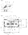
Die Vorrichtung zur Strommessung umfasst einen Magnetfeldsensor für die Messung des von einem durch einen Stromleiter fliessenden Stroms erzeugten Magnetfelds und ein Joch aus einem magnetischen Material mit hoher Permeabilität, das den Stromleiter im Messbereich-umgibt. Das Joch besteht im Prinzip aus einem länglichen Stück Blech mit zwei Enden, das durch Abbiegen in eine Form gebracht worden ist, bei der die Stirnseiten des Blechs einander gegenüberliegen und durch einen Luftspalt getrennt sind. Das Joch ist also wie ein Stück Rohr mit einem in Rohrrichtung verlaufenden Schlitz. Das Joch umschliesst den Stromleiter mit Ausnahme des Luftspalts vollständig.The current measuring device comprises a magnetic field sensor for measuring the magnetic field generated by a current flowing through a current conductor, and a yoke made of a high permeability magnetic material surrounding the current conductor in the measuring region. The yoke consists in principle of an elongated piece of sheet metal with two ends, which has been brought by bending in a mold in which the end faces of the sheet are opposite to each other and separated by an air gap. The yoke is therefore like a piece of pipe with a slot running in the pipe direction. The yoke completely encloses the conductor except for the air gap.
Der Magnetfeldsensor ist bevorzugt ein Magnetfeldsensor mit einem in einen Halbleiterchip integrierten Hallelement und einer in den Halbleiterchip integrierten elektronischen Schaltung für den Betrieb des Hallelementes und mit zwei auf der aktiven Oberseite des Halbleiterchips angeordneten, durch einen Luftspalt getrennten Magnetfeldkonzentratoren, wobei das Hallelement von Feldlinien des Magnetfeldes durchflutet wird, die vom ersten Magnetfeldkonzentrator in der Nähe des Luftspaltes weggehen und in der Nähe des Luftspaltes auf den zweiten Magnetfeldkonzentrator auftreffen.The magnetic field sensor is preferably a magnetic field sensor with a Hall element integrated in a semiconductor chip and an electronic circuit integrated in the semiconductor chip for operating the Hall element and with two magnetic field concentrators arranged on the active top side of the semiconductor chip and separated by an air gap, the Hall element being field lines of the magnetic field flooded, which go away from the first magnetic field concentrator in the vicinity of the air gap and impinge on the second magnetic field concentrator in the vicinity of the air gap.
Der Magnetfeldsensor kann aber auch ein anderer Sensor sein, z. B. ein AMR (anisotropic magnetic resistance) oder GMR (giant magnetic resistance) Sensor oder ein Fluxgate Sensor.The magnetic field sensor can also be another sensor, z. B. an AMR (anisotropic magnetic resistance) or GMR (giant magnetic resistance) sensor or a fluxgate sensor.
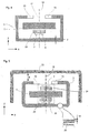
Das Joch dient einerseits der Verstärkung des vom Strom erzeugten Magnetfelds und andererseits der Abschirmung äusserer magnetischer Störfelder. Der Magnetfeldsensor und das Joch sind aufeinander abgestimmt derart, dass der Magnetfeldsensor nur empfindlich ist auf eine einzige Komponente des Magnetfelds, die beispielsweise als x-Komponente bezeichnet wird, und dass das Joch genau diese x-Komponente abschirmt. Der Magnetfeldsensor misst daher nur die x-Komponente des von dem im Stromleiter fliessenden Strom erzeugten Magnetfelds, nicht aber die abgeschirmte x-Komponente eines äusseren magnetischen Störfeldes. Um eine hohe Verstärkung zu erzielen, sind die Enden des Jochs verjüngt, so dass eine Breite der Enden des Jochs geringer als eine Breite des Jochs ist. Zudem ist die Ausdehnung des Jochs in der abzuschirmenden Richtung (also in der x-Richtung) mindestens so gross wie eine senkrecht dazu gemessene Höhe. Die Abschirmung kann weiter erhöht werden durch einen zusätzlichen, im wesentlichen u-förmigen, das Joch auf drei Seiten umschliessenden Schirm.The yoke serves on the one hand to amplify the magnetic field generated by the current and on the other hand to shield external magnetic interference fields. The magnetic field sensor and the yoke are matched to each other such that the magnetic field sensor is only sensitive to a single component of the magnetic field, which is referred to as x-component example, and that the yoke shields exactly this x-component. The magnetic field sensor therefore measures only the x-component of the magnetic field generated by the current flowing in the current conductor, but not the shielded x-component of an external magnetic interference field. To achieve high reinforcement, the ends of the yoke are tapered so that a width of the ends of the yoke is less than a width of the yoke. In addition, the extent of the yoke in the direction to be shielded (that is, in the x direction) is at least as large as a height measured perpendicular thereto. The shield can be further increased by an additional, substantially U-shaped, the yoke enclosing three sides screen.
Das Verhältnis von Abschirmungsfaktor zu Verstärkungsfaktor kann auch erhöht werden, indem die Enden des Jochs entweder verbreitert und/oder mit einer Ausnehmung versehen werden. Eine solche Ausgestaltung des Jochs eignet sich auch für die Messung von Strömen in einem vergleichsweise grossen Bereich von 0 bis 200A oder 300A, aber auch 1000A.The ratio of shielding factor to gain factor can also be increased by either widening the ends of the yoke and / or providing it with a recess. Such a configuration of the yoke is also suitable for the measurement of currents in a comparatively large range of 0 to 200A or 300A, but also 1000A.
Die Erfindung wird nachfolgend anhand von Ausführungsbeispielen und anhand der Zeichnung näher erläutert. Die Figuren sind schematisch und nicht massstäblich gezeichnet.
- Es zeigen: Fig. 1
- in perspektivischer Ansicht eine erfmdungsgemässe Vorrichtung zur Strommessung mit einem Magnetfeldsensor und einem Joch,
- Fig. 2
- ein Beispiel eines bevorzugten Magnetfeldsensors,
- Fig. 3
- die Vorrichtung zur Strommessung im Querschnitt,
- Fig. 4
- eine weitere Vorrichtung zur Strommessung im Querschnitt,
- Fig. 5
- eine weitere Vorrichtung zur Strommessung im Querschnitt,
- Fig. 6
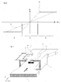
- Ausgangssignale der Vorrichtung zur Strommessung gemäss dem Ausführungsbeispiel der
Fig. 5 , und - Fig. 7, 8
- in perspektivischer Ansicht weitere Vorrichtungen zur Strommessung mit dem Magnetfeldsensor und dem Joch.
- FIG. 1 shows: FIG
- in a perspective view of a erfmdungsgemässe device for Current measurement with a magnetic field sensor and a yoke,
- Fig. 2
- an example of a preferred magnetic field sensor,
- Fig. 3
- the apparatus for current measurement in cross section,
- Fig. 4
- another device for current measurement in cross section,
- Fig. 5
- another device for current measurement in cross section,
- Fig. 6
- Output signals of the device for current measurement according to the embodiment of the
Fig. 5 , and - Fig. 7, 8
- in perspective view further devices for current measurement with the magnetic field sensor and the yoke.
Die
Ein bevorzugtes Beispiel für den Magnetfeldsensor 2 ist in der
Der Magnetfeldsensor 2 ist in ein Gehäuse 24 verpackt. Der Magnetfeldsensor 2 ist (bei Abwesenheit des Jochs 3) empfindlich auf ein Magnetfeld, das in x-Richtung verläuft, und unempfindlich auf Magnetfelder, die in y- und z-Richtung verlaufen. Die beiden Magnetfeldkonzentratoren 7 und 8 erstrecken sich in x-Richtung. Das Gehäuse 24 benötigt mehr Platz als im Luftspalt 14 des Jochs 3 zur Verfügung steht. Das Gehäuse 24 befindet sich somit innerhalb des Jochs 3, aber ausserhalb des Luftspalts 14.The
Der zwischen den Stirnseiten 12 und 13 der Enden 10 und 11 des Jochs 3 bestehende Luftspalt 14 befindet sich "oberhalb" des Luftspalts 6 zwischen den beiden Magnetfeldkonzentratoren 7 und 8, oder, geometrisch ausgedrückt: Es gibt eine senkrecht zur Oberfläche des Halbleiterchips 4 verlaufende Ebene, die sowohl durch den Luftspalt 6 als auch den Luftspalt 14 hindurch verläuft. Das Joch 3 und die beiden Magnetfeldkonzentratoren 7 und 8 bilden so einen durch den Luftspalt 6 und zwei weitere Luftspalte 15, 16 (siehe
Das Joch 3 erfüllt zwei Funktionen, nämlich einerseits die magnetische Verstärkung des von dem im Stromleiter fliessenden Strom erzeugten Magnetfelds und andererseits die Abschirmung des Magnetfeldsensors gegen äussere magnetische Störfelder. Aufgrund seiner Konstruktion ist der Magnetfeldsensor 2 unempfindlich gegen äussere Magnetfelder, die in y- und/oder z-Richtung gerichtet sind. Die Verstärkung des von dem im Stromleiter fliessenden Strom erzeugten Magnetfelds am Ort des Hallelements wird durch einen Verstärkungsfaktor charakterisiert. Der Verstärkungsfaktor ist abhängig von der Geometrie des Jochs 3, aber auch von der Frequenz des Stroms 1. Im folgenden ist unter dem Verstärkungsfaktor in der Regel der Verstärkungsfaktor bei Gleichstrom bzw. Wechselströmen unterhalb einer bestimmten Grenzfrequenz fG gemeint. Die Effizienz der Abschirmung des Magnetfeldsensors 2 gegen ein äusseres, in x-Richtung gerichtetes Magnetfeld wird durch einen Abschirmungsfaktor charakterisiert. Die Verjüngung der Enden 10 und 11 auf die Breite B0 bewirkt eine Erhöhung des Verstärkungsfaktors um den Faktor B/B0, während der Abschirmungsfaktor nahezu unverändert bleibt. Der Verstärkungsfaktor und der Abschirmungsfaktor hängen vom Abstand des Magnetfeldsensors 2 vom Luftspalt 14 zwischen den Enden 10 und 11 des Jochs 3 ab. Dieser Sachverhalt wird anhand der
Damit die Abschirmung eines in x-Richtung verlaufenden äusseren Magnetfelds wirksam ist, ist eine quer zum Stromleiter 1 und parallel zum Luftspalt 14 gemessene Länge L des Jochs 3 mindestens gleich gross wie eine senkrecht zum Luftspalt 14 gemessene Höhe H des Jochs 3. Bevorzugt ist die Länge L um mindestens den Faktor 1.5 grösser als die Höhe H.In order for the shielding of an external magnetic field running in the x-direction to be effective, a length L of the
Die ![]()
![]()
Die Dicke d des Blechs wird nun so gewählt, dass fG2 annähernd gleich fG1 ist. Mit abnehmender Dicke des Blechs und somit des Jochs 3 wird aber auch das Magnetfeld kleiner, das das Joch 3 magnetisch in Sättigung bringt. Um dies zu vermeiden, wird das Joch 3 als Laminat aus mehreren durch eine Isolationsschicht getrennten Blechen der Dicke d gebildet. Die Dicke d eines Blechs beträgt typischerweise etwa 0.02 bis 0.1, maximal 0.2 mm.The thickness d of the sheet is now selected so that f G2 is approximately equal to f G1 . With decreasing thickness of the sheet and thus of the
Die
Bei allen Beispielen kann der Abschirmungsfaktor durch einen zusätzlichen, im wesentlichen u-förmigen Schirm 21 aus einem Material mit hoher magnetischer Permeabilität vergrössert werden, der das Joch 3 auf drei Seiten umschliesst. Der Schirm 21 besteht aus drei Abschnitten, von denen der mittlere Abschnitt parallel zum Luftspalt 14 des Jochs 3 verläuft. Der Schirm 21 besteht vorzugsweise aus dem gleichen Material wie das Joch 3. Der Schirm 21 ist im Abstand E zum Joch 3 angeordnet. Der Abstand E ist so gross bemessen, dass der Schirm 21 den Verstärkungsfaktor des Jochs 3 nicht oder nur unwesentlich verkleinert.In all examples, the shielding factor may be increased by an additional substantially
Die
Die erfindungsgemässe Vorrichtung zur Strommessung zeichnet sich durch einen einfachen, kompakten Aufbau und eine einfache Montage aus. Das Gehäuse 24 mit dem Magnetfeldsensor 2 kann direkt auf den Stromleiter 1 geklebt werden. Alternativ kann das Gehäuse 24 auf einer Leiterplatte montiert und die Leiterplatte auf dem Stromleiter 1 befestigt werden. Ebenso kann das Joch 3 auf der gegenüberliegenden Seite direkt oder allenfalls über einen zusätzlichen Abstandshalter am Stromleiter 1 angeklebt werden.The inventive device for current measurement is characterized by a simple, compact design and easy installation. The
Der Magnetfeldsensor 2 bzw. 19 soll im wesentlichen nur empfindlich sein auf die x-Komponente eines äusseren Magnetfelds und unempfindlich auf die y- und z-Komponente des äusseren Magnetfelds. Der oben beschriebene Magnetfeldsensor mit den beiden Magnetfeldkonzentratoren und dem Hallelement erfüllt diese Anforderungen in hohem Masse. Der Magnetfeldsensor 2 bzw. 19 kann aber bei allen Beispielen auch ein anderer Sensor sein, der diese Anforderung erfüllt, z. B. ein AMR (anisotropic magnetic resistance) oder GMR (giant magnetic resistance) Sensor. Diese Sensoren umfassen ein ferromagnetisches Widerstandselement, dessen elektrischer Widerstand von der Stärke des Magnetfelds abhängt. Der Magnetfeldsensor 2 bzw. 19 kann des weiteren auch ein Fluxgate Sensor sein. Ein Fluxgate Sensor umfasst einen ferromagnetischen Kern. Das ferromagnetische Widerstandselement bzw. der ferromagnetische Kern ist auf der aktiven Oberfläche des Halbleiterchips 4 angeordnet. Das ferromagnetische Widerstandselement bzw. der ferromagnetische Kern beeinflusst den Verlauf der magnetischen Feldlinien in ähnlicher Weise wie die Magnetfeldkonzentratoren 7, 8 beim vorhergehenden Beispiel.The
Es sind auch abgewandelte Formen des Jochs möglich. Die beiden verjüngten, einander gegenüberliegenden Enden des Jochs könnten z. B. auch in der Form von aus den Seitenwänden des Jochs freigestanzten und abgebogenen Zungen bestehen.There are also modified forms of the yoke possible. The two tapered, opposite ends of the yoke could z. B. also in the form of cut out of the side walls of the yoke punched and bent tongues.
Die
Die gezeigten Beispiele illustrierten, dass die Vorrichtung zur Strommessung einzig durch Änderung der Form der Enden des Jochs 3 für die Messung unterschiedlich grosser Maximalströme ausgelegt werden kann. Der gleiche Magnetfeldsensor 2 kann auf die gleiche Weise und an der gleichen Position auf dem Stromleiter 1 montiert werden.The examples shown illustrated that the device for current measurement can be designed solely by changing the shape of the ends of the
Claims (6)
- Device for measuring current, comprising a magnetic field sensor (2) for measuring a magnetic field produced by a current flowing through a current conductor (1), the magnetic field sensor encapsulated into a housing (24), and a yoke (3) of a magnetic material having a relative permeability of at least 100, wherein the current conductor (1) has a rectangular cross section and a bottom side and a top side, wherein the current conductor (1) extends in relation to a Cartesian coordinate system having three axes designated as x-axis, y-axis and z-axis in the direction of the y-axis, in which the current flows, and the magnetic field sensor (2) is sensitive to that component of the magnetic field which extends in the direction of the x-axis, wherein the yoke (3) is formed of an oblong piece of sheet metal or a laminate of sheet metals and is formed by bending such that the yoke (3) has two sidewalls extending in the direction of the z-axis and two ends (10, 11) separated by an air gap (14), the front faces of which face each other, so that the yoke (3) completely circumscribes the current conductor (1) with the exception of the air gap (14), wherein the yoke has a length (L) measured in the direction of the x-axis and a height (H) measured in the direction of the y-axis, the housing (24) with the magnetic field sensor (2) is placed inside the yoke (3) and outside the air gap (14) of the yoke (3) and glued on the top side of the current conductor (1) or mounted on a printed circuit board and the printed circuit board fixed on the top side of the current conductor (1), the magnetic field sensor (2) comprises at least one Hall element (5A; 5B) and two magnetic field concentrators (7, 8) or is an AMR or GMR sensor, which comprises a ferromagnetic resistive element, or is a fluxgate sensor, which comprises a ferromagnetic core, wherein the magnetic field concentrators (7, 8) or the ferromagnetic resistive element or the ferromagnetic core are essentially passed through by stray lines of the magnetic field that issue from the ends (10, 11) of the yoke (3), the length (L) of the yoke (3) is at least the same size as the height (H) of the yoke (3), the magnetic field sensor (2) is placed at a distance (D) from the air gap (14) of the yoke (3) which is measured from the surface of the magnetic field concentrators (7, 8) or the ferromagnetic resistive element or the ferromagnetic core, wherein the distance (D) is less than a smallest distance (E) from the sidewalls of the yoke (3) which smallest distance is measured along the x-axis from the outer end of the magnetic field concentrators (7, 8) or the ferromagnetic resistive element or the ferromagnetic core, and the yoke (3) is secured directly or with distance keeping means to the bottom side of the current conductor (1).
- Device for measuring current according to claim 1, characterized in that the ends (10, 11) of the yoke (3) are tapered.
- Device for measuring current according to claim 1, characterized in that the ends (10, 11) of the yoke (3) are enlarged or provided with a recess or are enlarged and provided with a recess.
- Device for measuring current according to any of claims 1 to 3, characterized in that a further magnetic field sensor (19) is placed on the side of the current conductor (1) that faces the bottom side of the yoke (3).
- Device for measuring current according to any of claims 1 to 4, characterized in that the magnetic field sensor (2; 19) comprises a semiconductor chip (4) with at least one Hall element (5A; 5B), wherein two magnetic field concentrators (7, 8) are arranged on a top side of the semiconductor chip (4) wherein the Hall element (5A; 5B) is passed through by field lines (9) of the magnetic field that issue from the first magnetic field concentrator (7) in the vicinity of the further air gap (6) and impinge on the second magnetic field concentrator (8) in the vicinity of the further air gap (6).
- Device for measuring current according to any of claims 1 to 5, further comprising an essentially u-shaped screen (21) of a magnetic material with a relative permeability of at least 100 that borders the yoke (3) on three sides, wherein the screen (21) has three sections of which the middle section runs parallel to the air gap (14) of the yoke (3).
Applications Claiming Priority (3)
| Application Number | Priority Date | Filing Date | Title |
|---|---|---|---|
| CH962006 | 2006-01-19 | ||
| CH7392006 | 2006-05-08 | ||
| CH9852006 | 2006-06-14 |
Publications (2)
| Publication Number | Publication Date |
|---|---|
| EP1811311A1 EP1811311A1 (en) | 2007-07-25 |
| EP1811311B1 true EP1811311B1 (en) | 2016-08-31 |
Family
ID=37963562
Family Applications (1)
| Application Number | Title | Priority Date | Filing Date |
|---|---|---|---|
| EP07100349.5A Active EP1811311B1 (en) | 2006-01-19 | 2007-01-10 | Device for measuring current |
Country Status (3)
| Country | Link |
|---|---|
| US (1) | US7545136B2 (en) |
| EP (1) | EP1811311B1 (en) |
| JP (1) | JP5787243B2 (en) |
Cited By (2)
| Publication number | Priority date | Publication date | Assignee | Title |
|---|---|---|---|---|
| DE102021111412A1 (en) | 2021-05-03 | 2022-11-03 | Phoenix Contact Gmbh & Co. Kg | Current measuring system for measuring a current flowing through an electrical current conductor and a corresponding method |
| LU102798B1 (en) | 2021-05-03 | 2022-11-03 | Phoenix Contact Gmbh & Co | Current measuring system for measuring a current flowing through an electrical current conductor and a corresponding method |
Families Citing this family (45)
| Publication number | Priority date | Publication date | Assignee | Title |
|---|---|---|---|---|
| EP1811311B1 (en) | 2006-01-19 | 2016-08-31 | Melexis Technologies NV | Device for measuring current |
| DE102007003830B4 (en) * | 2007-01-25 | 2009-08-06 | Robert Seuffer Gmbh & Co. Kg | Device for measuring an electrical current flowing through an electrical conductor |
| DE102007062633B4 (en) * | 2007-12-22 | 2010-04-15 | Sensitec Gmbh | Arrangement for potential-free measurement of currents |
| AT506682B1 (en) * | 2008-04-17 | 2014-05-15 | Adaptive Regelsysteme Ges M B H | CURRENT MEASURING DEVICE AND METHOD FOR THE GALVANICALLY SEPARATED MEASUREMENT OF FLOWS |
| DE102008039568B4 (en) * | 2008-08-25 | 2015-03-26 | Seuffer gmbH & Co. KG | Current detection device |
| FR2936062B1 (en) * | 2008-09-12 | 2010-10-01 | Electricfil Automotive | OPEN LOOP CURRENT SENSOR WITH BROAD RANGE |
| US9222992B2 (en) | 2008-12-18 | 2015-12-29 | Infineon Technologies Ag | Magnetic field current sensors |
| JP5680287B2 (en) * | 2009-05-27 | 2015-03-04 | 新科實業有限公司SAE Magnetics(H.K.)Ltd. | Current sensor |
| CH702264A1 (en) * | 2009-11-30 | 2011-05-31 | Melexis Tessenderlo Nv | Device for measuring current flowing through current conductor for indicating charging condition of battery, has magnetic element and concentrator with end areas, and shield surrounding concentrator, where end areas overlap with each other |
| CH702301A2 (en) | 2009-11-30 | 2011-05-31 | Melexis Tessenderlo Nv | Device for measuring current. |
| US9086444B2 (en) * | 2009-12-28 | 2015-07-21 | Tdk Corporation | Magnetic field detection device and current sensor |
| US8717016B2 (en) | 2010-02-24 | 2014-05-06 | Infineon Technologies Ag | Current sensors and methods |
| US8760149B2 (en) | 2010-04-08 | 2014-06-24 | Infineon Technologies Ag | Magnetic field current sensors |
| US8680843B2 (en) * | 2010-06-10 | 2014-03-25 | Infineon Technologies Ag | Magnetic field current sensors |
| WO2011158633A1 (en) * | 2010-06-17 | 2011-12-22 | アイシン精機株式会社 | Current sensor and current sensor array |
| US8283742B2 (en) | 2010-08-31 | 2012-10-09 | Infineon Technologies, A.G. | Thin-wafer current sensors |
| CH703903B1 (en) | 2010-10-01 | 2014-04-30 | Melexis Tessenderlo Nv | Current sensor. |
| US8975889B2 (en) | 2011-01-24 | 2015-03-10 | Infineon Technologies Ag | Current difference sensors, systems and methods |
| US8963536B2 (en) | 2011-04-14 | 2015-02-24 | Infineon Technologies Ag | Current sensors, systems and methods for sensing current in a conductor |
| JP5690209B2 (en) * | 2011-05-17 | 2015-03-25 | Tdk株式会社 | Current sensor |
| CH705027A1 (en) * | 2011-05-30 | 2012-11-30 | Melexis Technologies Nv | Device for measuring a current flowing through an electric cable current. |
| DE102011080041A1 (en) * | 2011-07-28 | 2013-04-11 | Vacuumschmelze Gmbh & Co. Kg | Flow sensor assembly |
| JP5960403B2 (en) * | 2011-09-26 | 2016-08-02 | 矢崎総業株式会社 | Current sensor |
| JP2013117447A (en) * | 2011-12-02 | 2013-06-13 | Denso Corp | Current sensor |
| JP2013148512A (en) * | 2012-01-20 | 2013-08-01 | Aisin Seiki Co Ltd | Current sensor |
| DE102012202179B4 (en) * | 2012-02-14 | 2021-09-23 | Robert Bosch Gmbh | Magnetic field sensor and method for producing a magnetic field sensor |
| JP6296103B2 (en) * | 2013-03-11 | 2018-03-20 | 株式会社デンソー | Current sensor |
| JP2014199251A (en) | 2013-03-11 | 2014-10-23 | 株式会社デンソー | Current sensor |
| US20140266180A1 (en) * | 2013-03-15 | 2014-09-18 | Infineon Technologies Ag | Sensors, systems and methods for residual current detection |
| TWI504904B (en) * | 2013-07-30 | 2015-10-21 | Asahi Kasei Microdevices Corp | Current sensor |
| JP2015194472A (en) * | 2014-01-23 | 2015-11-05 | 株式会社デンソー | current detection system |
| US10168391B2 (en) * | 2015-06-23 | 2019-01-01 | Infineon Technologies Ag | Multi-functional interconnect module and carrier with multi-functional interconnect module attached thereto |
| US11422164B2 (en) | 2015-06-24 | 2022-08-23 | Currently, LLC | Contactless wideband magneto-resistive current sensor with low electromagnetic interference |
| RU2610223C1 (en) * | 2015-08-17 | 2017-02-08 | Акционерное общество "Научно-производственное объединение измерительной техники" | Method of noncontact measurement of surface current and device for its implementation |
| US9810721B2 (en) | 2015-12-23 | 2017-11-07 | Melexis Technologies Sa | Method of making a current sensor and current sensor |
| CN109313223B (en) * | 2016-06-15 | 2021-02-26 | 株式会社电装 | Current sensor |
| JP6790774B2 (en) * | 2016-12-06 | 2020-11-25 | アイシン精機株式会社 | Current sensor |
| JP6596033B2 (en) * | 2017-05-08 | 2019-10-23 | 矢崎総業株式会社 | Current sensor |
| JP6988684B2 (en) * | 2018-05-18 | 2022-01-05 | 株式会社デンソー | Current sensor |
| DE102018113005B4 (en) * | 2018-05-30 | 2024-02-01 | Infineon Technologies Austria Ag | MAGNETIC CURRENT SENSOR |
| EP3690450A1 (en) * | 2019-01-30 | 2020-08-05 | LEM International SA | Current transducer with magnetic field detector module |
| EP3789775B8 (en) * | 2019-09-04 | 2023-11-22 | BRUSA Technology AG | A high-power electronics assembly |
| DE102019124405A1 (en) * | 2019-09-11 | 2021-03-11 | Schaeffler Technologies AG & Co. KG | CURRENT SENSOR |
| JP7099483B2 (en) * | 2020-02-21 | 2022-07-12 | Tdk株式会社 | Current sensor |
| JP7215451B2 (en) * | 2020-03-19 | 2023-01-31 | Tdk株式会社 | CURRENT SENSOR AND MANUFACTURING METHOD THEREOF, ELECTRICAL CONTROL DEVICE, AND CURRENT SENSOR DESIGN METHOD |
Citations (2)
| Publication number | Priority date | Publication date | Assignee | Title |
|---|---|---|---|---|
| JPH04118561A (en) * | 1990-04-14 | 1992-04-20 | Toyota Autom Loom Works Ltd | Current sensor |
| EP0886147A1 (en) * | 1997-05-21 | 1998-12-23 | Electrowatt Technology Innovation AG | Device for obtaining a current-proportional magnetic induction at the position of a magnetic field sensor |
Family Cites Families (25)
| Publication number | Priority date | Publication date | Assignee | Title |
|---|---|---|---|---|
| US3344347A (en) | 1963-08-23 | 1967-09-26 | Bell Inc F W | Method and apparatus for determining displacement utilizing a hall plate positioned tangential to an arcuate magnetic field |
| US3323057A (en) * | 1966-05-02 | 1967-05-30 | Halmar Electronics | Hall generator current meter having extraneous field compensating apparatus |
| US3593118A (en) * | 1968-09-30 | 1971-07-13 | Montedoro Corp | Apparatus for measuring the electrical conductivity of liquids having dielectric-faced electrodes |
| US3800193A (en) | 1972-09-05 | 1974-03-26 | Ibm | Magnetic sensing device |
| GB2052855B (en) | 1979-03-30 | 1983-05-18 | Sony Corp | Magnetoresistive transducers |
| CH659138A5 (en) * | 1982-10-27 | 1986-12-31 | Landis & Gyr Ag | Arrangement for measuring the current flowing in an electrical conductor via the magnetic field generated by it |
| JPS6298267A (en) * | 1985-10-25 | 1987-05-07 | Matsushita Electric Works Ltd | Current detector |
| CH670004A5 (en) * | 1986-02-10 | 1989-04-28 | Landis & Gyr Ag | |
| JPH04148870A (en) * | 1990-10-12 | 1992-05-21 | Murata Mfg Co Ltd | Detection coil |
| JPH06130088A (en) * | 1992-10-15 | 1994-05-13 | Fujitsu Ltd | Current sensor |
| JPH0792199A (en) * | 1993-07-28 | 1995-04-07 | Matsushita Electric Ind Co Ltd | Current sensor |
| JPH0815322A (en) * | 1994-06-30 | 1996-01-19 | Hioki Ee Corp | Current sensor |
| EP0742440B1 (en) * | 1995-05-09 | 2002-02-20 | Vacuumschmelze GmbH | Compensated current conversion |
| US5717327A (en) * | 1995-09-22 | 1998-02-10 | Bradford; Melvin J. | Current sensor |
| EP0772046B1 (en) * | 1995-10-30 | 2002-04-17 | Sentron Ag | Magnetic field probe and current or energy probe |
| DE59609089D1 (en) | 1995-10-30 | 2002-05-23 | Sentron Ag Zug | Magnetic field sensor and current or energy sensor |
| US6545456B1 (en) | 1998-08-12 | 2003-04-08 | Rockwell Automation Technologies, Inc. | Hall effect current sensor package for sensing electrical current in an electrical conductor |
| US6426617B1 (en) | 1999-09-28 | 2002-07-30 | Rockwell Automation Technologies, Inc. | Hall effect current sensor system packaging |
| JP2003043074A (en) * | 2001-07-26 | 2003-02-13 | Asahi Kasei Corp | Current detector and its production method |
| US7129691B2 (en) | 2001-11-01 | 2006-10-31 | Sentron Ag | Current sensor and current sensor manufacturing method |
| JP2003302428A (en) * | 2002-04-09 | 2003-10-24 | Asahi Kasei Corp | Substrate mounting type current sensor and current measuring method |
| US6686730B2 (en) | 2002-06-11 | 2004-02-03 | Rockwell Automation Technologies, Inc. | Snap fit Hall effect circuit mount apparatus and method |
| JP2004170091A (en) * | 2002-11-15 | 2004-06-17 | Aichi Micro Intelligent Corp | Current sensor |
| JP2005195427A (en) * | 2004-01-06 | 2005-07-21 | Asahi Kasei Electronics Co Ltd | Current measurement system, current measurement method, and current measurement program |
| EP1811311B1 (en) | 2006-01-19 | 2016-08-31 | Melexis Technologies NV | Device for measuring current |
-
2007
- 2007-01-10 EP EP07100349.5A patent/EP1811311B1/en active Active
- 2007-01-16 US US11/653,627 patent/US7545136B2/en active Active
- 2007-01-17 JP JP2007007595A patent/JP5787243B2/en active Active
Patent Citations (2)
| Publication number | Priority date | Publication date | Assignee | Title |
|---|---|---|---|---|
| JPH04118561A (en) * | 1990-04-14 | 1992-04-20 | Toyota Autom Loom Works Ltd | Current sensor |
| EP0886147A1 (en) * | 1997-05-21 | 1998-12-23 | Electrowatt Technology Innovation AG | Device for obtaining a current-proportional magnetic induction at the position of a magnetic field sensor |
Cited By (2)
| Publication number | Priority date | Publication date | Assignee | Title |
|---|---|---|---|---|
| DE102021111412A1 (en) | 2021-05-03 | 2022-11-03 | Phoenix Contact Gmbh & Co. Kg | Current measuring system for measuring a current flowing through an electrical current conductor and a corresponding method |
| LU102798B1 (en) | 2021-05-03 | 2022-11-03 | Phoenix Contact Gmbh & Co | Current measuring system for measuring a current flowing through an electrical current conductor and a corresponding method |
Also Published As
| Publication number | Publication date |
|---|---|
| JP5787243B2 (en) | 2015-09-30 |
| EP1811311A1 (en) | 2007-07-25 |
| US7545136B2 (en) | 2009-06-09 |
| US20070164727A1 (en) | 2007-07-19 |
| JP2007192820A (en) | 2007-08-02 |
Similar Documents
| Publication | Publication Date | Title |
|---|---|---|
| EP1811311B1 (en) | Device for measuring current | |
| EP2530475B1 (en) | Device for measuring a current flowing through a cable | |
| EP2223128B1 (en) | Arrangement for the potential-free measurement of currents | |
| DE69920890T2 (en) | CURRENT SENSOR | |
| DE10392748B4 (en) | Current measuring method and current measuring device | |
| EP1772737A2 (en) | Assembly group for the current measurement | |
| EP1746426B1 (en) | Current sensor | |
| DE112016002481T5 (en) | current sensor | |
| DE112013002170T5 (en) | Magnetic sensor device | |
| WO2002056032A2 (en) | Device, ammeter and motor vehicle | |
| DE112007003025T5 (en) | Magnetic sensor and magnetic encoder that uses it | |
| DE102006007770A1 (en) | Sensor unit for detection of magnetic field intensity, has transducer unit contains transducer bridge connection with two parallely switched bridge arms, and each bridge arm has magnetic field transducer and arm unit switched in sequence | |
| DE102011004391A1 (en) | Calibratable magnetic field sensor and method of making the same | |
| DE102018114015A1 (en) | current sensor | |
| DE102018216319A1 (en) | current sensor | |
| DE60026952T2 (en) | current sensor | |
| DE10107811A1 (en) | Device, ammeter and motor vehicle | |
| DE102010035469A1 (en) | Sensor of device for examination of value document e.g. check, has magnetoresistive element positioned such that field of magnet at magnetoresistive element is oriented perpendicular to sensitivity direction of magnetoresistive element | |
| EP3417245B1 (en) | Sensor | |
| EP2333567B1 (en) | Device for measuring current | |
| DE2829264A1 (en) | DEVICE FOR CONTACT-FREE MEASUREMENT OF THE THICKNESS OF NON-MAGNETIC, RAIL-SHAPED MATERIAL | |
| DE102012202179B4 (en) | Magnetic field sensor and method for producing a magnetic field sensor | |
| DE102019213127A1 (en) | DEVICE FOR A NON-CONTACTIVE SENSOR WITH ESD PROTECTION STRUCTURE | |
| CH696859A5 (en) | Current sensor having a plurality of magnetic field sensors. | |
| DE3609006A1 (en) | Magnetic field sensor |
Legal Events
| Date | Code | Title | Description |
|---|---|---|---|
| PUAI | Public reference made under article 153(3) epc to a published international application that has entered the european phase |
Free format text: ORIGINAL CODE: 0009012 |
|
| AK | Designated contracting states |
Kind code of ref document: A1 Designated state(s): AT BE BG CH CY CZ DE DK EE ES FI FR GB GR HU IE IS IT LI LT LU LV MC NL PL PT RO SE SI SK TR |
|
| AX | Request for extension of the european patent |
Extension state: AL BA HR MK YU |
|
| 17P | Request for examination filed |
Effective date: 20080125 |
|
| 17Q | First examination report despatched |
Effective date: 20080228 |
|
| AKX | Designation fees paid |
Designated state(s): DE FR IT |
|
| RAP1 | Party data changed (applicant data changed or rights of an application transferred) |
Owner name: MELEXIS TESSENDERLO NV |
|
| RAP1 | Party data changed (applicant data changed or rights of an application transferred) |
Owner name: MELEXIS TECHNOLOGIES NV |
|
| GRAP | Despatch of communication of intention to grant a patent |
Free format text: ORIGINAL CODE: EPIDOSNIGR1 |
|
| INTG | Intention to grant announced |
Effective date: 20160523 |
|
| GRAS | Grant fee paid |
Free format text: ORIGINAL CODE: EPIDOSNIGR3 |
|
| GRAA | (expected) grant |
Free format text: ORIGINAL CODE: 0009210 |
|
| AK | Designated contracting states |
Kind code of ref document: B1 Designated state(s): DE FR IT |
|
| REG | Reference to a national code |
Ref country code: DE Ref legal event code: R096 Ref document number: 502007015061 Country of ref document: DE |
|
| REG | Reference to a national code |
Ref country code: FR Ref legal event code: PLFP Year of fee payment: 11 |
|
| REG | Reference to a national code |
Ref country code: DE Ref legal event code: R097 Ref document number: 502007015061 Country of ref document: DE |
|
| PLBE | No opposition filed within time limit |
Free format text: ORIGINAL CODE: 0009261 |
|
| STAA | Information on the status of an ep patent application or granted ep patent |
Free format text: STATUS: NO OPPOSITION FILED WITHIN TIME LIMIT |
|
| 26N | No opposition filed |
Effective date: 20170601 |
|
| REG | Reference to a national code |
Ref country code: FR Ref legal event code: PLFP Year of fee payment: 12 |
|
| PGFP | Annual fee paid to national office [announced via postgrant information from national office to epo] |
Ref country code: IT Payment date: 20190131 Year of fee payment: 13 Ref country code: FR Payment date: 20190129 Year of fee payment: 13 |
|
| PG25 | Lapsed in a contracting state [announced via postgrant information from national office to epo] |
Ref country code: FR Free format text: LAPSE BECAUSE OF NON-PAYMENT OF DUE FEES Effective date: 20200131 |
|
| PG25 | Lapsed in a contracting state [announced via postgrant information from national office to epo] |
Ref country code: IT Free format text: LAPSE BECAUSE OF NON-PAYMENT OF DUE FEES Effective date: 20200110 |
|
| PGFP | Annual fee paid to national office [announced via postgrant information from national office to epo] |
Ref country code: DE Payment date: 20221220 Year of fee payment: 17 |
|
| P01 | Opt-out of the competence of the unified patent court (upc) registered |
Effective date: 20230517 |