EP3918286B1 - Hybride verteilte akustische prüfung - Google Patents
Hybride verteilte akustische prüfung Download PDFInfo
- Publication number
- EP3918286B1 EP3918286B1 EP20708800.6A EP20708800A EP3918286B1 EP 3918286 B1 EP3918286 B1 EP 3918286B1 EP 20708800 A EP20708800 A EP 20708800A EP 3918286 B1 EP3918286 B1 EP 3918286B1
- Authority
- EP
- European Patent Office
- Prior art keywords
- mode
- backscattered
- signals
- stokes raman
- optical fiber
- Prior art date
- Legal status (The legal status is an assumption and is not a legal conclusion. Google has not performed a legal analysis and makes no representation as to the accuracy of the status listed.)
- Active
Links
Images



Classifications
-
- G—PHYSICS
- G01—MEASURING; TESTING
- G01H—MEASUREMENT OF MECHANICAL VIBRATIONS OR ULTRASONIC, SONIC OR INFRASONIC WAVES
- G01H9/00—Measuring mechanical vibrations or ultrasonic, sonic or infrasonic waves by using radiation-sensitive means, e.g. optical means
- G01H9/004—Measuring mechanical vibrations or ultrasonic, sonic or infrasonic waves by using radiation-sensitive means, e.g. optical means using fibre optic sensors
-
- G—PHYSICS
- G01—MEASURING; TESTING
- G01D—MEASURING NOT SPECIALLY ADAPTED FOR A SPECIFIC VARIABLE; ARRANGEMENTS FOR MEASURING TWO OR MORE VARIABLES NOT COVERED IN A SINGLE OTHER SUBCLASS; TARIFF METERING APPARATUS; MEASURING OR TESTING NOT OTHERWISE PROVIDED FOR
- G01D5/00—Mechanical means for transferring the output of a sensing member; Means for converting the output of a sensing member to another variable where the form or nature of the sensing member does not constrain the means for converting; Transducers not specially adapted for a specific variable
- G01D5/26—Mechanical means for transferring the output of a sensing member; Means for converting the output of a sensing member to another variable where the form or nature of the sensing member does not constrain the means for converting; Transducers not specially adapted for a specific variable characterised by optical transfer means, i.e. using infrared, visible, or ultraviolet light
- G01D5/32—Mechanical means for transferring the output of a sensing member; Means for converting the output of a sensing member to another variable where the form or nature of the sensing member does not constrain the means for converting; Transducers not specially adapted for a specific variable characterised by optical transfer means, i.e. using infrared, visible, or ultraviolet light with attenuation or whole or partial obturation of beams of light
- G01D5/34—Mechanical means for transferring the output of a sensing member; Means for converting the output of a sensing member to another variable where the form or nature of the sensing member does not constrain the means for converting; Transducers not specially adapted for a specific variable characterised by optical transfer means, i.e. using infrared, visible, or ultraviolet light with attenuation or whole or partial obturation of beams of light the beams of light being detected by photocells
- G01D5/353—Mechanical means for transferring the output of a sensing member; Means for converting the output of a sensing member to another variable where the form or nature of the sensing member does not constrain the means for converting; Transducers not specially adapted for a specific variable characterised by optical transfer means, i.e. using infrared, visible, or ultraviolet light with attenuation or whole or partial obturation of beams of light the beams of light being detected by photocells influencing the transmission properties of an optical fibre
- G01D5/35338—Mechanical means for transferring the output of a sensing member; Means for converting the output of a sensing member to another variable where the form or nature of the sensing member does not constrain the means for converting; Transducers not specially adapted for a specific variable characterised by optical transfer means, i.e. using infrared, visible, or ultraviolet light with attenuation or whole or partial obturation of beams of light the beams of light being detected by photocells influencing the transmission properties of an optical fibre using other arrangements than interferometer arrangements
- G01D5/35354—Sensor working in reflection
- G01D5/35358—Sensor working in reflection using backscattering to detect the measured quantity
- G01D5/35361—Sensor working in reflection using backscattering to detect the measured quantity using elastic backscattering to detect the measured quantity, e.g. using Rayleigh backscattering
-
- G—PHYSICS
- G01—MEASURING; TESTING
- G01D—MEASURING NOT SPECIALLY ADAPTED FOR A SPECIFIC VARIABLE; ARRANGEMENTS FOR MEASURING TWO OR MORE VARIABLES NOT COVERED IN A SINGLE OTHER SUBCLASS; TARIFF METERING APPARATUS; MEASURING OR TESTING NOT OTHERWISE PROVIDED FOR
- G01D5/00—Mechanical means for transferring the output of a sensing member; Means for converting the output of a sensing member to another variable where the form or nature of the sensing member does not constrain the means for converting; Transducers not specially adapted for a specific variable
- G01D5/26—Mechanical means for transferring the output of a sensing member; Means for converting the output of a sensing member to another variable where the form or nature of the sensing member does not constrain the means for converting; Transducers not specially adapted for a specific variable characterised by optical transfer means, i.e. using infrared, visible, or ultraviolet light
- G01D5/32—Mechanical means for transferring the output of a sensing member; Means for converting the output of a sensing member to another variable where the form or nature of the sensing member does not constrain the means for converting; Transducers not specially adapted for a specific variable characterised by optical transfer means, i.e. using infrared, visible, or ultraviolet light with attenuation or whole or partial obturation of beams of light
- G01D5/34—Mechanical means for transferring the output of a sensing member; Means for converting the output of a sensing member to another variable where the form or nature of the sensing member does not constrain the means for converting; Transducers not specially adapted for a specific variable characterised by optical transfer means, i.e. using infrared, visible, or ultraviolet light with attenuation or whole or partial obturation of beams of light the beams of light being detected by photocells
- G01D5/353—Mechanical means for transferring the output of a sensing member; Means for converting the output of a sensing member to another variable where the form or nature of the sensing member does not constrain the means for converting; Transducers not specially adapted for a specific variable characterised by optical transfer means, i.e. using infrared, visible, or ultraviolet light with attenuation or whole or partial obturation of beams of light the beams of light being detected by photocells influencing the transmission properties of an optical fibre
- G01D5/35338—Mechanical means for transferring the output of a sensing member; Means for converting the output of a sensing member to another variable where the form or nature of the sensing member does not constrain the means for converting; Transducers not specially adapted for a specific variable characterised by optical transfer means, i.e. using infrared, visible, or ultraviolet light with attenuation or whole or partial obturation of beams of light the beams of light being detected by photocells influencing the transmission properties of an optical fibre using other arrangements than interferometer arrangements
- G01D5/35354—Sensor working in reflection
- G01D5/35358—Sensor working in reflection using backscattering to detect the measured quantity
- G01D5/35364—Sensor working in reflection using backscattering to detect the measured quantity using inelastic backscattering to detect the measured quantity, e.g. using Brillouin or Raman backscattering
-
- G—PHYSICS
- G01—MEASURING; TESTING
- G01K—MEASURING TEMPERATURE; MEASURING QUANTITY OF HEAT; THERMALLY-SENSITIVE ELEMENTS NOT OTHERWISE PROVIDED FOR
- G01K11/00—Measuring temperature based upon physical or chemical changes not covered by groups G01K3/00, G01K5/00, G01K7/00 or G01K9/00
- G01K11/32—Measuring temperature based upon physical or chemical changes not covered by groups G01K3/00, G01K5/00, G01K7/00 or G01K9/00 using changes in transmittance, scattering or luminescence in optical fibres
- G01K11/3206—Measuring temperature based upon physical or chemical changes not covered by groups G01K3/00, G01K5/00, G01K7/00 or G01K9/00 using changes in transmittance, scattering or luminescence in optical fibres at discrete locations in the fibre, e.g. using Bragg scattering
-
- G—PHYSICS
- G01—MEASURING; TESTING
- G01N—INVESTIGATING OR ANALYSING MATERIALS BY DETERMINING THEIR CHEMICAL OR PHYSICAL PROPERTIES
- G01N21/00—Investigating or analysing materials by the use of optical means, i.e. using sub-millimetre waves, infrared, visible or ultraviolet light
- G01N21/17—Systems in which incident light is modified in accordance with the properties of the material investigated
- G01N21/47—Scattering, i.e. diffuse reflection
-
- G—PHYSICS
- G01—MEASURING; TESTING
- G01K—MEASURING TEMPERATURE; MEASURING QUANTITY OF HEAT; THERMALLY-SENSITIVE ELEMENTS NOT OTHERWISE PROVIDED FOR
- G01K11/00—Measuring temperature based upon physical or chemical changes not covered by groups G01K3/00, G01K5/00, G01K7/00 or G01K9/00
- G01K11/32—Measuring temperature based upon physical or chemical changes not covered by groups G01K3/00, G01K5/00, G01K7/00 or G01K9/00 using changes in transmittance, scattering or luminescence in optical fibres
- G01K11/324—Measuring temperature based upon physical or chemical changes not covered by groups G01K3/00, G01K5/00, G01K7/00 or G01K9/00 using changes in transmittance, scattering or luminescence in optical fibres using Raman scattering
-
- G—PHYSICS
- G01—MEASURING; TESTING
- G01N—INVESTIGATING OR ANALYSING MATERIALS BY DETERMINING THEIR CHEMICAL OR PHYSICAL PROPERTIES
- G01N21/00—Investigating or analysing materials by the use of optical means, i.e. using sub-millimetre waves, infrared, visible or ultraviolet light
- G01N21/17—Systems in which incident light is modified in accordance with the properties of the material investigated
- G01N21/47—Scattering, i.e. diffuse reflection
- G01N2021/4704—Angular selective
- G01N2021/4709—Backscatter
Definitions
- This instant specification relates to optical fiber vibration and temperature sensors.
- the fiber optic paradigm is particularly unique, given its numerous advantages, including immunity to electromagnetic interference, miniature sizes, harsh environment operation, and capability of large-scale multiplexing.
- the ⁇ -OTDR based DAS has been deployed in applications such as real time structural health monitoring, oil and gas industry, and aerospace transportation. Its operation principle consists of launching a train of optical pulses generated by a narrow linewidth laser into a fiber under test (FUT). At the FUT input port, consecutive Rayleigh backscattered traces are recorded in the time domain. Each Rayleigh trace has a speckle-like profile because of coherent interference of the signals reflected by scattering centers within the injected pulse duration. In the absence of intrusion along the FUT, (such as no refractive index perturbation) the recorded Rayleigh traces are ideally identical.
- the effective refractive index changes at this position, and consequently the intrusion of vibrations from the acoustic signal can be sensed by observing the intensity fluctuation of a corresponding speckle in the recorded traces.
- DTS distributed temperature sensing
- the backscattered power of the Raman signal within an optical fiber is roughly 40 dB (decibels) less than that of the Rayleigh signal. Consequently, in DTS systems, the pump powers that are employed can induce nonlinearity in single mode fibers (SMFs). This fiber nonlinearity, such as stimulated Raman scattering, inhibits the proper operation of DTS systems. Alternatively, multimode fibers (MMFs), which exhibit relatively greater nonlinearity threshold in comparison with SMFs, are used for DTS systems. However, it is difficult to offer MMF-based DAS system because MMF supports propagating huge numbers of modes, and each mode encounters independent interference behavior that is detrimental to Rayleigh signals.
- CN 103 913 186 injects light into an optical fiber through a wavelength division multiplexer.
- Backward scattered Rayleigh light is directed to a first photodetector to obtain vibration information.
- Stokes and anti-Stokes Raman scattered light enter a second photodetector and are used to obtain a temperature measure.
- WO 2016/111849 describes a system that can simultaneously use a forward-propagating signal and a backward-scattered signal in few mode or multi mode fibers.
- the system is used to transmit a signal and perform fault sensing simultaneously.
- US 2015/0114127 describes distributed acoustic and temperature sensing using a multi-mode optical fiber.
- a method for remotely sensing vibration and temperature includes separating, by a wavelength division multiplexing filter and from a few mode optical fiber, a collection of backscattered Rayleigh signals based on a vibration of the few mode optical fiber at a vibration frequency at a first location along the few mode optical fiber.
- a collection of backscattered Stokes Raman signals and Anti-Stokes Raman signals is separated by the wavelength division multiplexing filter and from the few mode optical fiber, based on a temperature of the few mode optical fiber at a second location along the few mode optical fiber.
- the separated Rayleigh signals are detected and the separated Stokes Raman signals and Anti-Stokes Raman signals are detected.
- At least one of the first location in the few mode optical fiber of the vibration, the vibration frequency, and an amplitude of the vibration is determined based on the detecting the collection of backscattered Rayleigh traces. Then the temperature of the few mode fiber at the second location is determined based on the detecting the collection of backscattered Stokes Raman signals and Anti-Stokes Raman signals.
- the method also includes demultiplexing, from the few mode optical fiber, the separated backscattered Rayleigh signals, and providing the demultiplexed Rayleigh signals to a single mode optical fiber, wherein detecting the separated Rayleigh signals further comprises detecting the demultiplexed separated Rayleigh signals from the single mode optical fiber.
- the method can also include demultiplexing, from the few mode optical fiber, the separated backscattered Stokes Raman signals and backscattered Anti-Stokes Raman signals, and providing the demultiplexed Stokes Raman signals and Anti-Stokes Raman signals to the single mode optical fiber, wherein detecting the separated Stokes Raman signals and Anti-Stokes Raman signals can also include detecting the demultiplexed separated Stokes Raman signals and Anti-Stokes Raman signals.
- the method also includes transmitting a collection of optical pulses through a single mode optical fiber at a predetermined frequency, and injecting the optical pulses into the few mode optical fiber as a predetermined mode through a mode multiplexer.
- Transmitting a collection of optical pulses through a single mode optical fiber at a predetermined frequency can include generating, by a light source, continuous-wave light, converting, by a first optical modulator, the continuous-wave light into the collection of optical pulses having the predetermined frequency, amplifying, by an optical amplifier, the collection of optical pulses, directing the optical pulses to a first port of an optical circulator, and directing, by the optical circulator, the optical pulses to a second port of the optical circulator in optical communication with the single mode optical fiber.
- the method can also include receiving, at the second port of the optical circulator, the backscattered Rayleigh signals, and directing the backscattered Rayleigh signals to a third port of the optical circulator, wherein detecting the separated Rayleigh signals can also include receiving the separated Rayleigh signals from the third port.
- Transmitting a collection of optical pulses through an single mode optical fiber at a predetermined frequency can include transmitting, by a first optical transmitter, a first collection of optical pulses through a first single mode optical fiber to a first port of the multiplexer, and the method can also include transmitting a second collection of optical pulses through a second single mode optical fiber to a second port of the multiplexer.
- a vibration and temperature sensor system includes: a first single mode optical fiber, a few mode optical fiber having a predetermined length, a first light pulse generator configured to provide a first collection of optical pulses to the single mode optical fiber, a multiplexer configured to multiplex optical pulses received from the first single mode optical fiber at a first multiplexer port to the few mode optical fiber, a wavelength division multiplexing filter configured to receive and separate from the few mode optical fiber backscattered Rayleigh signals, backscattered Stokes Raman signals, and backscattered Anti-Stokes Raman signals, and a demultiplexer configured to demultiplex at least one of backscattered Rayleigh signals, backscattered Stokes Raman signals, and backscattered Anti-Stokes Raman signals, from the few mode fiber to the first single mode fiber at a first demultiplexer port.
- a first sensor is configured to determine at least one of a first location of a vibration in the few mode optical fiber, a frequency of the vibration, and an amplitude of the vibration, based on the backscattered Rayleigh signals
- a second sensor is configured to determine at least one of a second location in the few mode fiber and a temperature at the second location, based on backscattered Stokes Raman signals and backscattered Anti-Stokes Raman signals.
- the first sensor can be configured to receive demultiplexed backscattered Rayleigh signals from the demultiplexer at the first demultiplexer port.
- the second sensor can be configured to receive demultiplexed backscattered Stokes Raman signals and demultiplexed backscattered Anti-Stokes Raman signals from the demultiplexer at the first demultiplexer port.
- the second sensor can be configured to receive separated backscattered Stokes Raman signals and separated backscattered Anti-Stokes Raman signals from the wavelength division multiplexing filter.
- the vibration sensor can also include a second single mode optical fiber, a second light pulse generator configured to provide a second collection of optical pulses to the single mode optical fiber, wherein the multiplexer is further configured to multiplex optical pulses, received from the second single mode optical fiber at a second multiplexer port, to the few mode optical fiber, and wherein the demultiplexer is further configured to demultiplex at least one of backscattered Rayleigh signals, backscattered Stokes Raman signals, and backscattered Anti-Stokes Raman signals, from the few mode fiber to the second single mode fiber at a second demultiplexer port, a third sensor configured to determine at least one of a third location in the few mode fiber and a temperature at the third location, based on backscattered Stokes Raman signals and backscattered Anti-Stokes Raman signals.
- the third sensor can be configured to receive demultiplexed backscattered Stokes Raman signals and demultiplexed backscattered Anti-Stokes Raman signals from the demultiplexer at the second demultiplexer port.
- the third sensor can be configured to receive separated backscattered Stokes Raman signals and separated backscattered Anti-Stokes Raman signals from the wavelength division multiplexing filter.
- the vibration sensor can also include a fourth sensor configured to determine at least one of a fourth location of a vibration in the few mode optical fiber, a frequency of the vibration, and an amplitude of the vibration, based on the backscattered Rayleigh signals.
- the fourth sensor can be configured to receive demultiplexed backscattered Rayleigh signals from the demultiplexer at the second demultiplexer port.
- a non-transitory computer storage medium according to claim 13 is provided.
- a system can provide simultaneous distributed vibration and temperature sensing using a single platform, which reduces the overall cost of the two individual systems.
- the system offers DAS with longer sensing range compared with the SMF-based DAS.
- this design mitigates the dispersion problem found in the typical MMF-based DTS.
- Optical fibers can be used as a distributed acoustic sensor (DAS) or as a distributed temperature sensor (DTS).
- DAS distributed acoustic sensor
- DTS distributed temperature sensor
- the systems and techniques described in this document enable simultaneous measurement of vibration and temperature, remove the need for separate DAS and DTS systems, reduce overall cost, and ensure continuous real-time monitoring of parameters along the pipelines.
- combining the DAS and DTS systems is quite challenging because DAS and DTS implementations use different configurations.
- the backscattered power of a Raman signal within an optical fiber is roughly 40 dB (decibels) less than that of a Rayleigh signal. Consequently, for DTS systems, the amount of pump power employed can induce nonlinearity in single mode fibers (SMFs).
- SMFs single mode fibers
- MMFs Multimode fibers
- FMF In general, to resolve the fiber nonlinearity dilemma and simultaneously keep the DAS operation reliable, a few-mode-fiber (FMF) is used as a compromise between SMF and MMF.
- FMF has the following characteristics: 1) commercially available mode multiplexers/demultiplexers (MUX/DEMUX) can be used to easily launch and extract individual modes into and from a FMF, 2) the power threshold of nonlinearity of FMF is higher than that of the SMF, 3) a FMF guides a restricted number of spatial modes, typically less than 20 modes, such that intermodal coupling and differential mode group delays within the FMF can be controlled and managed.
- MUX/DEMUX mode multiplexers/demultiplexers
- a FMF guides a restricted number of spatial modes, typically less than 20 modes, such that intermodal coupling and differential mode group delays within the FMF can be controlled and managed.
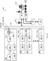
- FIG. 1 is a schematic diagram that shows an example of a system 100 for remotely sensing vibration and temperature.
- the system 100 is a hybrid optical fiber distributed acoustic sensor (DAS) and distributed temperature sensor (DTS) system that includes a computing system 110, a sensor system 120, and a fiber under test (FUT) 130.
- the computing system 110 is in electronic communication with the sensor system 120 (such as through a network connection or a universal serial bus connection).
- the FUT 130 is an optical fiber that is optically coupled to the sensor system 120 at a proximal end 122 and extends a distance (multiple kilometers, for example) to a distal end 124.
- a vibration source 150 emits vibrations 152 at a particular frequency.
- the vibrations 152 intersect the FUT 130 and vibrate the FUT 130 at, near, or around a location 160.
- a thermal source 170 emits heat energy 172 that changes the temperature of the FUT 103 at, near, or around a location 180.
- the system 100 uses a technique that improves the performance of both DTS and DAS using the same FUT.
- a fiber mode multiplexer/demultiplexer and a few-mode fiber (FMF) is used to improve signal discrimination among multiple optical backscatterings.
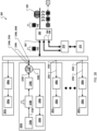
- FIG. 2A is a block diagram that shows an example of a system 200 for remotely sensing vibration and temperature.
- the system 200 can be the example system 100 of FIG. 1 .
- the system 200 includes a light pulse assembly 201a.
- a light source 210a of the light pulse assembly 201a emits light into a single mode fiber (SMF) 212a.
- the light source 210a is a narrow-linewidth (1 kilohertz (kHz), for example) laser source that generates continuous-wave (CW) light.
- the laser light is modulated by a modulator 214a to produce optical pulses.
- the modulated light is amplified by an optical amplifier 216a.
- the amplified modulated light is provided to an optical port 222a of an optical circulator 220a.
- the optical circulator 220a provides the amplified modulated light to an optical port 224a that is optically coupled to a proximal end 232a of a single mode fiber 230a.
- the optical amplifier 216a may be omitted.
- a distal end 234a of the single mode fiber 230a is optically coupled to an optical port 242a of a mode multiplexer (MUX) 240.
- the mode multiplexer 240 is an optical coupler that allows several standard single mode optical fiber inputs to be selectively converted into the individual modes of a few mode fiber (FMF) 250.
- FMF few mode fiber
- mode multiplexer 240 is configured to couple the optical port 242a to mode 0 (zero) of the few mode fiber 250.
- the term "multiplexer” includes bidirectional mode multiplexer/demultiplexers (MUX/DEMUX).
- the mode multiplexer 240 is also a mode demultiplexer that allows individual modes of a few mode fiber at an optical fiber input to be selectively converted into the individual single mode optical fibers.
- a device that is configured to perform only mode multiplexing may be used in cooperation with a device that is configured to perform only mode demultiplexing.
- WDM wavelength division multiplexing
- the few mode fiber 250 several kilometers (km) long (such as 4 km), but this is just one example. In various implementations, any appropriate length of fiber can be used.
- the few mode fiber 250 can be strung along a region to be monitored, and vibrations and temperatures from sources can be monitored along a region near the few mode fiber 250.
- the few mode fiber 250 could be extended in buildings, oil/gas wells, or industrial sites to sense vibrations and temperatures, which might be produced by structural cracks, oil/gas flows, or human/machines activities.
- the Raman scattering As a launched pulse propagates within the few mode fiber 250, part of its power is backscattered by the optical phenomena such as Rayleigh scattering, Stokes Raman scattering, and anti-Stokes Raman scattering.
- Rayleigh scattering When photons are scattered from an atom or molecule, most of them are elastically scattered (Rayleigh scattering). A fraction of the scattered photons are scattered inelastically by an excitation (Raman Effect), with the scattered photons having a frequency and energy different from, and usually less than, those of the incident photons.
- the Raman interaction leads to two possible outcomes. In one outcome, the material that interacts with the photons absorbs some of the photons' energy and the emitted photons have less energy than the absorbed photons. This outcome is referred to as Stokes Raman scattering. In the other outcome, the material loses energy and the emitted photons have more energy than the absorbed photons. This outcome is labeled anti-Stokes Raman scatter
- the bidirectional WDM filter 260 separates the Rayleigh, Stokes Raman, and Anti-Stokes Raman signals.
- the two Stokes Raman signal is directed to a port 264, and the Anti-Stokes Raman signal is directed to a port 266.
- the Stokes Raman and Anti-Stokes Raman signals are directed towards a receiver 270 for light detection and data acquisition.
- a signal processor 272 processes the acquired Raman data and provides information that describes the distribution of temperatures along the few mode fiber 250.
- the receiver 270 can include an optical amplifier.
- a photodetector can be configured to convert light intensities into electrical signals.
- the filtered backscattered traces can be sensed by the photodetector, and the photodetector can provide representative electrical signals to an analog-to-digital (A/D) converter.
- the analog-to-digital converter can be configured to sample the electrical signals from the photodetector and provide representative digital data to the signal processor 272 for further processing, presentation (for example, to a user), or both.
- the spectrally filtered backscattered Rayleigh signal is directed by the WDM 260 filter through the Rayleigh port 262 to the mode multiplexer 240.
- the mode multiplexer 240 directs the backscattered signal to the optical port 242a or another one of a collection of optical ports 242b-242n.
- the optical pulses were directed to mode 0 (zero) of the few mode fiber 250, then most of the backscattered Rayleigh signals will be returned though mode 0, and as such, the backscattered signals will be demultiplexed to the optical port 242a and the single mode fiber 230a.
- the remaining backscattered Rayleigh signals guided by other modes of the few mode fiber 250 will be directed to other ports of the mode multiplexer 240.
- Signals backscattered on mode 1 are demultiplexed to the optical port 242b and guided to a light pulse assembly 201b by a single mode fiber 230b.
- Signals backscattered on mode 2 are demultiplexed to the optical port 242c and guided to a light pulse assembly 201c by a single mode fiber 230c.
- Signals backscattered on mode N are demultiplexed to the optical port 242n and guided to a light pulse assembly 201n by a single mode fiber 230n.
- the Rayleigh signals are directed by the optical circulator 220a to an optical port 226a that is optically coupled to a receiver 280a for amplification, detection, and data acquisition.
- a signal processor 282a (such as a computer, an oscilloscope) processes the acquired Rayleigh data and provides information that describes the distribution of vibration locations, amplitudes, and frequencies along the few mode fiber 250.
- the Rayleigh signals are directed by the mode multiplexer 240 a receiver 280b for amplification, detection, and data acquisition.
- a signal processor 282b (such as a computer, an oscilloscope) processes the acquired Rayleigh data and provides information that describes the distribution of vibration locations, amplitudes, and frequencies along the few mode fiber 250.
- the Rayleigh signals are directed by the mode multiplexer 240 a receiver 280c for amplification, detection, and data acquisition.
- a signal processor 282c processes the acquired Rayleigh data and provides information that describes the distribution of vibration locations, amplitudes, and frequencies along the few mode fiber 250.
- the Rayleigh signals are directed by the mode multiplexer 240 a receiver 280n for amplification, detection, and data acquisition.
- a signal processor 282n (such as a computer, an oscilloscope) processes the acquired Rayleigh data and provides information that describes the distribution of vibration locations, amplitudes, and frequencies along the few mode fiber 250.
- the receivers 280a-208n can include an optical amplifier.
- the Rayleigh traces can be amplified by the erbium-doped fiber amplifier, and the amplified spontaneous emission (ASE) noise of the amplified traces can be filtered out by a fiber Bragg grating.
- a photodetector can configured to convert light intensities into electrical signals.
- the filtered backscattered traces can be sensed by the photodetector, and the photodetector can provide representative electrical signals to an analog-to-digital (A/D) converter.
- the analog-to-digital converter can be configured to sample the electrical signals from the photodetector and provide representative digital data to the signal processors 282a-282n for further processing, presentation (for example, to a user), or both.
- FIG. 2B is a block diagram that shows an example of the system 200 in a configuration that transmits light pulses and receives most of the backscattered Rayleigh signals using mode 1 of the few mode fiber 250.
- the system 200 includes the light pulse assembly 201b.
- the light pulse assembly 201b has a configuration and use that is similar to the light pulse assembly 201a.
- a light source 210b of the light pulse assembly 201b emits continuous-wave (CW) light into a single mode fiber (SMF) 212b.
- the laser light is modulated by a modulator 214b to produce optical pulses.
- CW continuous-wave
- SMF single mode fiber
- the modulated light is amplified by an optical amplifier 216b.
- the amplified modulated light is provided to an optical port 222b of an optical circulator 220b.
- the optical circulator 220b provides the amplified modulated light to an optical port 224b that is optically coupled to a proximal end 232b of a single mode fiber 230b.
- the optical amplifier 216b may be omitted.
- a distal end 234b of the single mode fiber 230b is optically coupled to the optical port 242b of a mode multiplexer (MUX) 240.
- mode multiplexer 240 is configured to couple the optical port 242b to mode 1 (one) of the few mode fiber 250.
- the spectrally filtered backscattered Rayleigh signal is directed by the WDM 260 filter through the Rayleigh port 262 to the mode multiplexer 240.
- the WDM 260 filter since the optical pulses were directed to mode 1 (one) of the few mode fiber 250, then most of the backscattered Rayleigh signals will be returned though mode 1, and as such the backscattered signals will be demultiplexed to the optical port 242b and the single mode fiber 230b.
- the Rayleigh signals are directed by the optical circulator 220b to an optical port 226b that is optically coupled to a receiver 280b for amplification, detection, and data acquisition.
- a signal processor 282b (such as a computer, an oscilloscope) processes the acquired Rayleigh data and provides information that describes the distribution of vibration locations, amplitudes, and frequencies along the few mode fiber 250.
- the Rayleigh signals are directed by the mode multiplexer 240 the receiver 280a for amplification, detection, and data acquisition.
- the signal processor 282a processes the acquired Rayleigh data and provides information that describes the distribution of vibration locations, amplitudes, and frequencies along the few mode fiber 250.
- the Rayleigh signals are directed by the mode multiplexer 240 the receiver 280c for amplification, detection, and data acquisition.
- the signal processor 282c processes the acquired Rayleigh data and provides information that describes the distribution of vibration locations, amplitudes, and frequencies along the few mode fiber 250.
- the Rayleigh signals are directed by the mode multiplexer 240 the receiver 280n for amplification, detection, and data acquisition.
- the signal processor 282n processes the acquired Rayleigh data and provides information that describes the distribution of vibration locations, amplitudes, and frequencies along the few mode fiber 250.
- FIG. 3A is a block diagram that shows an example of a system 300 for remotely sensing vibration and temperature.
- the system 300 can be the example system 100 of FIG. 1 .
- the system 300 includes a light pulse assembly 301a.
- a light source 310a of the light pulse assembly 301a emits light into a single mode fiber (SMF) 312a.
- the light source 310a is a narrow-linewidth (1 kHz, for example) laser source that generates continuous-wave (CW) light.
- the laser light is modulated by a modulator 314a to produce optical pulses.
- the modulated light is amplified by an optical amplifier 316a.
- the amplified modulated light is provided to an optical port 322a of an optical circulator 320a.
- the optical circulator 320a provides the amplified modulated light to an optical port 324a that is optically coupled to a proximal end 332a of a single mode fiber 330a.
- the optical amplifier 316a may be omitted.
- a distal end 334a of the single mode fiber 330a is optically coupled to an optical port 342a of a mode multiplexer (MUX) 340.
- the mode multiplexer 340 is an optical coupler that allows several standard single mode optical fiber inputs to be selectively converted into the individual modes of a few mode fiber (FMF) 350.
- FMF few mode fiber
- mode multiplexer 340 is configured to couple the optical port 342a to mode 0 (zero) of the few mode fiber 350.
- the term "multiplexer” includes bidirectional mode multiplexer/demultiplexers (MUX/DEMUX).
- the mode multiplexer 340 is also a mode demultiplexer that allows individual modes of a few mode fiber at an optical fiber input to be selectively converted into the individual single mode optical fibers.
- a device that is configured to perform only mode multiplexing may be used in cooperation with a device that is configured to perform only mode demultiplexing.
- the few mode fiber 350 can be several kilometers (km) long (such as 4 km), but this is just one example. In various implementations, any appropriate length of fiber can be used. In some implementations, the few mode fiber 350 can be strung along a region to be monitored, and vibrations and temperatures from sources can be monitored along a region near the few mode fiber 350. For example, the few mode fiber 350 could be extended in buildings, oil/gas wells, or industrial sites to sense vibrations and temperatures, which might be produced, by structural cracks, oil/gas flows, or human/machines activities.
- the mode multiplexer 340 directs the backscattered signal to the optical port 342a or another one of a collection of optical ports 342b-342n.
- the optical pulses were directed to mode 0 (zero) of the few mode fiber 350, then most of the backscattered signals will be returned though mode 0, and as such, the backscattered signals will be demultiplexed to the optical port 342a and the single mode fiber 330a.
- the backscattered signals on mode 0 are directed by the optical circulator 320a to an optical port 326a that is optically coupled to a wavelength division multiplexing (WDM) filter 360a which spectrally resolves Rayleigh, Stokes Raman, and Anti-Stokes Raman signals.
- WDM wavelength division multiplexing
- the WDM filter 360a separates the Rayleigh, Stokes Raman, and Anti-Stokes Raman signals.
- the Rayleigh signal is directed to a port 362a
- the Stokes Raman signal is directed to a port 364a
- the Anti-Stokes Raman signal is directed to a port 366a.
- the Stokes Raman and Anti-Stokes Raman signals are directed towards a receiver 370a for light detection and data acquisition.
- a signal processor 372 processes the acquired Raman data and provides information that describes the distribution of temperatures along the few mode fiber 350.
- the receiver 370a can include an optical amplifier.
- a photodetector can configured to convert light intensities into electrical signals.
- the filtered backscattered traces can be sensed by the photodetector, and the photodetector can provide representative electrical signals to an analog-to-digital (A/D) converter.
- the analog-to-digital converter can be configured to sample the electrical signals from the photodetector and provide representative digital data to the signal processor 372 for further processing, presentation (for example, to a user), or both.
- the Rayleigh signals are directed by the WDM 360a to a receiver 380a for amplification, detection, and data acquisition.
- a signal processor 382a (such as a computer, an oscilloscope) processes the acquired Rayleigh data and provides information that describes the distribution of vibration locations, amplitudes, and frequencies along the few mode fiber 350.
- the receiver 380a can include an optical amplifier.
- the Rayleigh traces can be amplified by the erbium-doped fiber amplifier, and the amplified spontaneous emission (ASE) noise of the amplified traces can be filtered out by a fiber Bragg grating.
- a photodetector can configured to convert light intensities into electrical signals.
- the filtered backscattered traces can be sensed by the photodetector, and the photodetector can provide representative electrical signals to an analog-to-digital (A/D) converter.
- the analog-to-digital converter can be configured to sample the electrical signals from the photodetector and provide representative digital data to the signal processor 382a for further processing, presentation (for example, to a user), or both.
- the remaining backscattered signals guided by other modes of the few mode fiber 350 will be directed to other ports of the mode multiplexer 340.
- Signals backscattered on mode 1 are demultiplexed to the optical port 342b and guided to a light pulse assembly 301b by a single mode fiber 330b.
- Signals backscattered on mode n are demultiplexed to the optical port 342n and guided to a light pulse assembly 301n by a single mode fiber 330n.
- FIG. 3B is a block diagram that shows an example of the system 300 in a configuration that transmits light pulses and receives most of backstattered signals using mode 1 of the few mode fiber 350.
- the system 300 includes the light pulse assembly 301b.
- a light source 310b of the light pulse assembly 301b emits light into a single mode fiber (SMF) 312b.
- the light source 310b is a narrow-linewidth (1 kHz, for example) laser source that generates continuous-wave (CW) light.
- the laser light is modulated by a modulator 314b to produce optical pulses.
- the modulated light is amplified by an optical amplifier 316b.
- the amplified modulated light is provided to an optical port 322b of an optical circulator 320b.
- the optical circulator 320b provides the amplified modulated light to an optical port 324b that is optically coupled to a proximal end 332b of the single mode fiber 330b.
- the optical amplifier 316b may be omitted.
- a distal end 334b of the single mode fiber 330b is optically coupled to an optical port 342b of the mode multiplexer (MUX) 340.
- mode multiplexer 340 is configured to couple the optical port 342b to mode 1 (one) of the few mode fiber 350.
- the term "multiplexer” includes bidirectional mode multiplexer/demultiplexers (MUX/DEMUX).
- the mode multiplexer 340 is also a mode demultiplexer that allows individual modes of a few mode fiber at an optical fiber input to be selectively converted into the individual single mode optical fibers.
- a device that is configured to perform only mode multiplexing may be used in cooperatively with a device that is configured to perform only mode demultiplexing.
- the backscattered light is directed to the mode multiplexer 340.
- the mode multiplexer 340 directs the backscattered signal to the optical port 342b or another one of the optical ports 342b-342n.
- the optical pulses were directed to mode 1 (one) of the few mode fiber 350, then most of the backscattered signals will be returned though mode 1, and as such the backscattered signals will be demultiplexed to the optical port 342b and the single mode fiber 330b.
- the backscattered signals on mode 1 are directed by the optical circulator 320b to an optical port 326b that is optically coupled to a wavelength division multiplexing (WDM) filter 360b which spectrally resolves Rayleigh, Stokes Raman, and Anti-Stokes Raman signals.
- WDM wavelength division multiplexing
- the WDM filter 360b separates the Rayleigh, Stokes Raman, and Anti-Stokes Raman signals.
- the Rayleigh signal is directed to a port 362b
- the Stokes Raman signal is directed to a port 364b
- the Anti-Stokes Raman signal is directed to a port 366b.
- the Stokes Raman and Anti-Stokes Raman signals are directed towards a receiver 370b for light detection and data acquisition.
- the signal processor 372 processes the acquired Raman data and provides information that describes the distribution of temperatures along the few mode fiber 350.
- the receiver 370b can include an optical amplifier.
- a photodetector can configured to convert light intensities into electrical signals.
- the filtered backscattered traces can be sensed by the photodetector, and the photodetector can provide representative electrical signals to an analog-to-digital (A/D) converter.
- the analog-to-digital converter can be configured to sample the electrical signals from the photodetector and provide representative digital data to the signal processor 372 for further processing, presentation (for example, to a user), or both.
- the Rayleigh signals are directed by the WDM 360b to a receiver 380b for amplification, detection, and data acquisition.
- a signal processor 382b (such as a computer, an oscilloscope) processes the acquired Rayleigh data and provides information that describes the distribution of vibration locations, amplitudes, and frequencies along the few mode fiber 350.
- the receiver 380b can include an optical amplifier.
- the Rayleigh traces can be amplified by the erbium-doped fiber amplifier, and the amplified spontaneous emission (ASE) noise of the amplified traces can be filtered out by a fiber Bragg grating.
- a photodetector can configured to convert light intensities into electrical signals.
- the filtered backscattered traces can be sensed by the photodetector, and the photodetector can provide representative electrical signals to an analog-to-digital (A/D) converter.
- the analog-to-digital converter can be configured to sample the electrical signals from the photodetector and provide representative digital data to the signal processor 382b for further processing, presentation (for example, to a user), or both.
- the remaining backscattered signals guided by other modes of the few mode fiber 350 will be directed to other ports of the mode multiplexer 340.
- Signals backscattered on mode 0 are demultiplexed to the optical port 342a and guided to a light pulse assembly 301a by a single mode fiber 330a.
- Signals backscattered on mode n are demultiplexed to the optical port 342n and guided to a light pulse assembly 301n by a single mode fiber 330n.
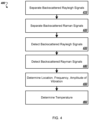
- FIG. 4 is a flow chart that shows an example of a process 400 for optical fiber vibration and temperature sensing.
- the process 400 may be performed, for example, by a system such as the example system 100, the example system 200, and the example system 300.
- a wavelength division multiplexing filter separates, from a few mode optical fiber, a collection of backscattered Rayleigh signals based on a vibration of a few mode optical fiber at a vibration frequency at a first location along the few mode optical fiber.
- the WDM 260 separates backscattered Rayleigh signals received from the few mode optical fiber 250.
- the wavelength division multiplexing filter separates from the few mode optical fiber a collection of backscattered Stokes Raman signals and Anti-Stokes Raman signals based on a temperature of the few mode optical fiber at a second location along the few mode optical fiber.
- the WDM 260 separates backscattered Raman signals received from the few mode optical fiber 250.
- the separated Rayleigh signals are detected.
- receiver 280a detects the Rayleigh signals and converts them to electrical signals.
- the separated Stokes Raman signals and Anti-Stokes Raman signals are detected.
- the receiver 270 detects the Raman signals and converts them to electrical signals.
- At 450 at least one of the first location in the few mode optical fiber of the vibration, the vibration frequency, and an amplitude of the vibration is determined based on the detecting the collection of backscattered Rayleigh traces.
- the signal processor 282a can analyze the signals provided by the receiver 280a to determine the location of the vibration 152, the frequency of the vibrations 152, the amplitude of the vibrations 152, or any appropriate combination of these.
- the temperature of the few mode fiber at the second location is determined based on the detecting the collection of backscattered Stokes Raman signals and Anti-Stokes Raman signals.
- the process 400 includes demultiplexing from the few mode optical fiber the separated backscattered Rayleigh signals, and providing the demultiplexed Rayleigh signals to a single mode optical fiber, wherein detecting the separated Rayleigh signals also includes detecting the demultiplexed separated Rayleigh signals from the single mode optical fiber.
- the mode multiplexer 240 can demultiplex the Rayleigh signals that are separated by the WDM 260, from the few mode fiber 250 to the single mode fiber 230a, 230b, ..., 230n, after which the Rayleigh signals are sensed by the receiver 280a, 280b, ..., 280n, and processed by the signal processor 282a, 282b, ..., 282n.
- the process 400 can also include demultiplexing, from the few mode optical fiber, the separated backscattered Stokes Raman signals and backscattered Anti-Stokes Raman signals, and providing the demultiplexed Stokes Raman signals and Anti-Stokes Raman signals to the single mode optical fiber, wherein detecting the separated Stokes Raman signals and Anti-Stokes Raman signals also includes detecting the demultiplexed separated Stokes Raman signals and Anti-Stokes Raman signals.
- the mode multiplexer 340 receives backscattered Raman signals from the few mode fiber 350.
- the mode multiplexer 340 demultiplexes the backscattered Raman signals from the few mode fiber 350 to the single mode fiber 330a, 330b, ..., 330n.
- the demultiplexed Stokes Raman signals and Anti-Stokes Raman signals are detected by the receiver 370a, 370b, ..., 370n, and processed by the signal processor 372.
- the process 400 also includes transmitting a collection of optical pulses through a single mode optical fiber at a predetermined frequency, and injecting the optical pulses into the few mode optical fiber as a predetermined mode through a mode multiplexer.
- the light pulse assembly 201a can emit optical pulses into the single mode fiber 230a.
- the optical pulses are injected into the few mode optical fiber 250 as mode 0 via the mode multiplexer 340.
- transmitting a collection of optical pulses through a single mode optical fiber at a predetermined frequency can include generating, by a light source, continuous-wave light, converting, by a first optical modulator, the continuous-wave light into the collection of optical pulses having the predetermined frequency, amplifying, by an optical amplifier, the collection of optical pulses, directing the optical pulses to a first port of an optical circulator, and directing, by the optical circulator, the optical pulses to a second port of the optical circulator in optical communication with the single mode optical fiber.
- the light source 210a of the light pulse assembly 201a can emit light into the single mode fiber 212a.
- the laser light is modulated by the modulator 214a to produce optical pulses.
- the modulated light is amplified by the optical amplifier 216a.
- the amplified modulated light is provided to the optical port 222a of the optical circulator 220a.
- the optical circulator 220a provides the amplified modulated light to the optical port 224a that is optically coupled to the proximal end 232a of the single mode fiber 230a.
- the process 400 can also include receiving, at the second port of the optical circulator, the backscattered Rayleigh signals, and directing the backscattered Rayleigh signals to a third port of the optical circulator, wherein detecting the separated Rayleigh signals also includes receiving the separated Rayleigh signals from the third port.
- the Rayleigh signals are directed by the optical circulator 220a to the optical port 226a that is optically coupled to the receiver 280a for amplification, detection, and data acquisition.
- transmitting a collection of optical pulses through an single mode optical fiber at a predetermined frequency can include sub-steps.
- a first optical transmitter can transmit a first collection of optical pulses through a first single mode optical fiber to a first port of the multiplexer.
- the process 400 can also include transmitting a second collection of optical pulses through a second single mode optical fiber to a second port of the multiplexer.
- the light pulse assembly 201a can transmit light pulses to the port 242a
- the light pulse assembly 201b can transmit light pulses to the port 242b.
- Implementations of the subject matter and the functional operations described in this specification can be implemented in digital electronic circuitry, in tangibly embodied computer software or firmware, in computer hardware, including the structures disclosed in this specification and their structural equivalents, or in combinations of one or more of them.
- Software implementations of the described subject matter can be implemented as one or more computer programs, that is, one or more modules of computer program instructions encoded on a tangible, non-transitory, computer-readable computer-storage medium for execution by, or to control the operation of, data processing apparatus.
- the program instructions can be encoded in/on an artificially generated propagated signal, for example, a machine-generated electrical, optical, or electromagnetic signal that is generated to encode information for transmission to suitable receiver apparatus for execution by a data processing apparatus.
- the computer-storage medium can be a machine-readable storage device, a machine-readable storage substrate, a random or serial access memory device, or a combination of computer-storage mediums.
- data processing apparatus refers to data processing hardware and encompass all kinds of apparatus, devices, and machines for processing data, including by way of example, a programmable processor, a computer, or multiple processors or computers.
- the apparatus can also be, or further include special purpose logic circuitry, for example, a central processing unit (CPU), a field programmable gate array (FPGA), or an application specific integrated circuit (ASIC).
- the data processing apparatus or special purpose logic circuitry may be hardware- or software-based (or a combination of both hardware- and software-based).
- the apparatus can optionally include code that creates an execution environment for computer programs, for example, code that constitutes processor firmware, a protocol stack, a database management system, an operating system, or a combination of execution environments.
- code that constitutes processor firmware for example, code that constitutes processor firmware, a protocol stack, a database management system, an operating system, or a combination of execution environments.
- the present disclosure contemplates the use of data processing apparatuses with or without conventional operating systems, for example LINUX, UNIX, WINDOWS, MAC OS, ANDROID, or IOS, or any other suitable conventional operating system.
- a computer program which may also be referred to or described as a program, software, a software application, a module, a software module, a script, or code, can be written in any form of programming language, including compiled or interpreted languages, or declarative or procedural languages, and it can be deployed in any form, including as a stand-alone program or as a module, component, subroutine, or other unit suitable for use in a computing environment.
- a computer program may, but need not, correspond to a file in a file system.
- a program can be stored in a portion of a file that holds other programs or data, for example, one or more scripts stored in a markup language document, in a single file dedicated to the program in question, or in multiple coordinated files, for example, files that store one or more modules, sub programs, or portions of code.
- a computer program can be deployed to be executed on one computer or on multiple computers that are located at one site or distributed across multiple sites and interconnected by a communication network. While portions of the programs illustrated in the various figures are shown as individual modules that implement the various features and functionality through various objects, methods, or other processes, the programs may instead include a number of sub-modules, third-party services, components, libraries, and such, as appropriate. Conversely, the features and functionality of various components can be combined into single components, as appropriate. Thresholds used to make computational determinations can be statically, dynamically, or both statically and dynamically determined.
- the methods, processes, or logic flows described in this specification can be performed by one or more programmable computers executing one or more computer programs to perform functions by operating on input data and generating output.
- the methods, processes, or logic flows can also be performed by, and apparatus can also be implemented as, special purpose logic circuitry, for example, a CPU, an FPGA, or an ASIC.
- Computers suitable for the execution of a computer program can be based on general or special purpose microprocessors, both, or any other kind of CPU.
- a CPU will receive instructions and data from and write to a memory.
- the essential elements of a computer are a CPU for performing or executing instructions and one or more memory devices for storing instructions and data.
- a computer will also include, or be operatively coupled to, receive data from or transfer data to, or both, one or more mass storage devices for storing data, for example, magnetic, magneto optical disks, or optical disks.
- mass storage devices for storing data, for example, magnetic, magneto optical disks, or optical disks.
- a computer need not have such devices.
- a computer can be embedded in another device, for example, a mobile telephone, a personal digital assistant (PDA), a mobile audio or video player, a game console, a global positioning system (GPS) receiver, or a portable storage device, for example, a universal serial bus (USB) flash drive, to name just a few.
- PDA personal digital assistant
- GPS global positioning system
- USB universal serial bus
- Computer readable media suitable for storing computer program instructions and data includes all forms of permanent/non-permanent or volatile/nonvolatile memory, media and memory devices, including by way of example semiconductor memory devices, for example, random access memory (RAM), read only memory (ROM), phase change memory (PRAM), static random access memory (SRAM), dynamic random access memory (DRAM), erasable programmable read-only memory (EPROM), electrically erasable programmable read-only memory (EEPROM), and flash memory devices; magnetic devices, for example, tape, cartridges, cassettes, internal/removable disks; magneto optical disks; and optical memory devices, for example, digital video disc (DVD), CD ROM, DVD+/-R, DVD-RAM, DVD-ROM, HD-DVD, and BLURAY, and other optical memory technologies.
- RAM random access memory
- ROM read only memory
- PRAM phase change memory
- SRAM static random access memory
- DRAM dynamic random access memory
- EPROM erasable programmable read-only memory
- the memory may store various objects or data, including caches, classes, frameworks, applications, modules, backup data, jobs, web pages, web page templates, data structures, database tables, repositories storing dynamic information, and any other appropriate information including any parameters, variables, algorithms, instructions, rules, constraints, or references thereto. Additionally, the memory may include any other appropriate data, such as logs, policies, security or access data, reporting files, as well as others.
- the processor and the memory can be supplemented by, or incorporated in, special purpose logic circuitry.
- implementations of the subject matter described in this specification can be implemented on a computer having a display device, for example, a cathode ray tube (CRT), liquid crystal display (LCD), light-emitting diode (LED), or plasma monitor, for displaying information to the user and a keyboard and a pointing device, for example, a mouse, trackball, or trackpad, by which the user can provide input to the computer.
- a display device for example, a cathode ray tube (CRT), liquid crystal display (LCD), light-emitting diode (LED), or plasma monitor
- a keyboard and a pointing device for example, a mouse, trackball, or trackpad, by which the user can provide input to the computer.
- Input may also be provided to the computer using a touchscreen.
- a computer can interact with a user by sending documents to and receiving documents from a device that is used by the user; for example, by sending web pages to a web browser on a user's client device in response to requests received from the web browser.
- GUI graphical user interface
- GUI may be used in the singular or the plural to describe one or more graphical user interfaces and each of the displays of a particular graphical user interface. Therefore, a GUI may represent any graphical user interface, including but not limited to, a web browser, a touch screen, or a command line interface (CLI) that processes information and efficiently presents the information results to the user.
- a GUI may include a collection of user interface (Ul) elements, some or all associated with a web browser, such as interactive fields, pull-down lists, and buttons. These and other UI elements may be related to or represent the functions of the web browser.
- Implementations of the subject matter described in this specification can be implemented in a computing system that includes a back end component, for example, as a data server, or that includes a middleware component, for example, an application server, or that includes a front-end component, for example, a client computer having a graphical user interface or a Web browser through which a user can interact with some implementations of the subject matter described in this specification, or any combination of one or more such back end, middleware, or front end components.
- the components of the system can be interconnected by any form or medium of wireline or wireless digital data communication (or a combination of data communication), for example, a communication network.
- Examples of communication networks include a local area network (LAN), a radio access network (RAN), a metropolitan area network (MAN), a wide area network (WAN), Worldwide Interoperability for Microwave Access (WIMAX), a wireless local area network (WLAN) using, for example, 802.11 a/b/g/n or 802.20 (or a combination of 802.11x and 802.20 or other protocols consistent with this disclosure), all or a portion of the Internet, or any other communication system or systems at one or more locations (or a combination of communication networks).
- the network may communicate with, for example, Internet Protocol (IP) packets, Frame Relay frames, Asynchronous Transfer Mode (ATM) cells, voice, video, data, or other suitable information (or a combination of communication types) between network addresses.
- IP Internet Protocol
- ATM Asynchronous Transfer Mode
- the computing system can include clients and servers.
- a client and server are generally remote from each other and typically interact through a communication network.
- the relationship of client and server arises by virtue of computer programs running on the respective computers and having a client-server relationship to each other.
Landscapes
- Physics & Mathematics (AREA)
- General Physics & Mathematics (AREA)
- Health & Medical Sciences (AREA)
- Life Sciences & Earth Sciences (AREA)
- Chemical & Material Sciences (AREA)
- Analytical Chemistry (AREA)
- Biochemistry (AREA)
- General Health & Medical Sciences (AREA)
- Immunology (AREA)
- Pathology (AREA)
- Measuring Temperature Or Quantity Of Heat (AREA)
- Optical Communication System (AREA)
Claims (13)
- Verfahren (400) zum ferngesteuerten Erfassen von Vibrationen und Temperaturen, wobei das Verfahren umfasst:Übertragen einer Vielzahl von optischen Pulsen durch eine Einzelmodus-Lichtleiterfaser mit einer vorbestimmten Frequenz;Injizieren der optischen Pulse aus der Einzelmodus-Lichtleiterfaser in eine Vielmoden-Lichtleiterfaser als einen vorbestimmten Modus durch einen bidirektionalen Modus-Multiplexer/Demultiplexer;Separieren (410), durch einen Wellenlängen-Multiplexfilter und von der Vielmoden-Lichtleiterfaser, einer Vielzahl von zurückgestreuten Rayleigh-Signalen basierend auf einer Vibration der Vielmoden-Lichtleiterfaser mit einer Vibrationsfrequenz an einem ersten Ort entlang der Vielmoden-Lichtleiterfaser;Modus-Demultiplexen der separierten zurückgestreuten Rayleigh-Signale von der Vielmoden-Lichtleiterfaser unter Verwendung des bidirektionalen Modus-Multiplexers/Demultiplexers;Bereitstellen, unter Verwendung des bidirektionalen Modus-Multiplexers/Demultiplexers, der Modusdemultiplexten Rayleigh-Signale für die Einzelmodus-Lichtleiterfaser;Separieren (420), durch den Wellenlängen-Multiplexfilter und von der Vielmoden-Lichtleiterfaser, einer Vielzahl von zurückgestreuten Stokes-Raman-Signalen und zurückgestreuten Anti-Stokes-Raman-Signalen basierend auf einer Temperatur der Vielmoden-Lichtleiterfaser an einem zweiten Ort entlang der Vielmoden-Lichtleiterfaser;Erkennen (430) der separierten Rayleigh-Signale, wobei das Erkennen der separierten Rayleigh-Signale ferner ein Erkennen der demultiplexten separierten Rayleigh-Signale von der Einzelmodus-Lichtleiterfaser umfasst;Erkennen (440) der separierten Stokes-Raman-Signale und der separierten Anti-Stokes-Raman-Signale;Ermitteln(450), basierend auf dem Erkennen der Vielzahl von zurückgestreuten Rayleigh-Spuren, mindestens eines von dem ersten Ort der Vibration in der Vielmoden-Lichtleiterfaser, der Vibrationsfrequenz und einer Amplitude der Vibration; undErmitteln (460), basierend auf dem Erkennen der Vielzahl von zurückgestreuten Stokes-Raman-Signalen und zurückgestreuten Anti-Stokes-Raman-Signale, der Temperatur der Vielmoden-Faser an dem zweiten Ort.
- Verfahren nach Anspruch 1, das ferner umfasst:Demultiplexen der separierten zurückgestreuten Stokes-Raman-Signale und der separierten zurückgestreuten Anti-Stokes-Raman-Signale von der Vielmoden-Lichtleiterfaser unter Verwendung eines Modus-Demultiplexers; undBereitstellen der demultiplexten Stokes-Raman-Signale und der demultiplexten Anti-Stokes-Raman-Signale für die Einzelmodus-Lichtleiterfaser;wobei das Erkennen der separierten Stokes-Raman-Signale und der separierten Anti-Stokes-Raman-Signale ferner ein Erkennen der demultiplexten separierten Stokes-Raman-Signale und der demultiplexten separierten Anti-Stokes-Raman-Signale umfasst.
- Verfahren nach Anspruch 1, wobei das Übertragen einer Vielzahl von optischen Pulsen durch die Einzelmodus-Lichtleiterfaser mit einer vorbestimmten Frequenz umfasst:Erzeugen, durch eine Lichtquelle einer kontinuierlichen Lichtwelle;Umwandeln, durch einen ersten optischen Modulator, der kontinuierlichen Lichtwelle in die Vielzahl von optischen Pulsen, welche die vorbestimmte Frequenz aufweisen;Verstärken, durch einen optischen Verstärker, der Vielzahl von optischen Pulsen;Leiten der optischen Pulse zu einem ersten Anschluss eines optischen Zirkulators; undLeiten, durch den optischen Zirkulator, der optischen Pulse zu einem zweiten Anschluss des optischen Zirkulators, der in einer optischen Kommunikation mit der Einzelmodus-Lichtleiterfaser steht.
- Verfahren nach Anspruch 3, das ferner umfasst:Empfangen, an dem zweiten Anschluss des optischen Zirkulators, der zurückgestreuten Rayleigh-Signale; undLeiten der zurückgestreuten Rayleigh-Signale zu einem dritten Anschluss des optischen Zirkulators;wobei das Erkennen der separierten Rayleigh-Signale ferner ein Empfangen der separierten Rayleigh-Signale von dem dritten Anschluss umfasst.
- Verfahren nach einem der Ansprüche 1 bis 4, wobei das Übertragen einer Vielzahl von optischen Pulsen durch eine Einzelmodus-Lichtleiterfaser mit einer vorbestimmten Frequenz ein Übertragen, durch einen ersten optischen Sender, einer ersten Vielzahl von optischen Pulsen durch eine Einzelmodus-Lichtleiterfaser zu einem ersten Anschluss des bidirektionalen Modus-Multiplexers/Demultiplexers umfasst, und wobei das Verfahren ferner ein Übertragen einer zweiten Vielzahl von optischen Pulsen durch eine zweite Einzelmodus-Lichtleiterfaser zu einem zweiten Anschluss des bidirektionalen Modus-Multiplexers/Demultiplexers umfasst.
- Sensorsystem zum ferngesteuerten Erfassen von Vibrationen und Temperaturen, wobei das Sensorsystem umfasst:eine erste Einzelmodus-Lichtleiterfaser;eine Vielmoden-Lichtleiterfaser, die eine vorbestimmte Länge aufweist;einen ersten Lichtpulsgenerator, der konfiguriert ist zum Bereitstellen einer ersten Vielzahl von optischen Pulsen für die Einzelmodus-Lichtleiterfaser;einen bidirektionalen Modus-Multiplexer/Demultiplexer, der konfiguriert ist zum i) Multiplexen von optischen Pulsen, die von der ersten Einzelmodus-Lichtleiterfaser an einem ersten Anschluss empfangen werden, für die Vielmoden-Lichtleiterfaser und ii) Demultiplexen von mindestens einem der zurückgestreuten Rayleigh-Signale, der zurückgestreuten Stokes-Raman-Signale und der zurückgestreuten Anti-Stokes-Raman-Signale, die von der Vielmoden-Lichtleiterfaser kommen, für die erste Einzelmodus-Lichtleiterfaser an dem ersten Anschluss;einen Wellenlängen-Multiplexfilter, der konfiguriert ist zum Empfangen und Separieren von zurückgestreuten Rayleigh-Signalen, zurückgestreuten Stokes-Raman-Signalen und zurückgestreuten Anti-Stokes-Raman-Signalen, die von der Vielmoden-Lichtleiterfaser kommen;einen ersten Sensor, der konfiguriert ist zum Ermitteln, basierend auf den zurückgestreuten Rayleigh-Signalen, mindestens eines von einem ersten Ort einer Vibration in der Vielmoden-Lichtleiterfaser, einer Frequenz der Vibration und einer Amplitude der Vibration;einen zweiten Sensor, der konfiguriert ist zum Ermitteln, basierend auf den zurückgestreuten Stokes-Raman-Signalen und den zurückgestreuten Anti-Stokes-Raman-Signalen, mindestens eines von einem zweiten Ort in der Vielmoden-Lichtleiterfaser und einer Temperatur an dem zweiten Ort.
- Sensorsystem nach Anspruch 6, wobei der erste Sensor konfiguriert ist zum Empfangen von demultiplexten zurückgestreuten Rayleigh-Signalen von dem bidirektionalen Modus-Multiplexer/Demultiplexer an dem ersten Anschluss.
- Sensorsystem nach Anspruch 6 oder 7, wobei der zweite Sensor konfiguriert ist zum Empfangen von demultiplexten zurückgestreuten Stokes-Raman-Signalen und von demultiplexten zurückgestreuten Anti-Stokes-Raman-Signalen von dem bidirektionalen Modus-Multiplexer/Demultiplexer an dem ersten Anschluss.
- Sensorsystem nach einem der Ansprüche 6 bis 8, wobei der zweite Sensor konfiguriert ist zum Empfangen von separierten zurückgestreuten Stokes-Raman-Signalen und von separierten zurückgestreuten Anti-Stokes-Raman-Signalen von dem Wellenlängen-Multiplexfilter.
- Sensorsystem nach einem der Ansprüche 6 bis 9, das ferner umfasst:eine zweite Einzelmodus-Lichtleiterfaser;einen zweiten Lichtpulsgenerator, der konfiguriert ist zum Bereitstellen einer zweiten Vielzahl von optischen Pulsen für die Einzelmodus-Lichtleiterfaser, wobei der bidirektionale Modus-Multiplexer/Demultiplexer ferner konfiguriert zum Multiplexen von optischen Pulsen, die von der zweiten Einzelmodus-Lichtleiterfaser an einem zweiten Anschluss empfangen werden, für die Vielmoden-Lichtleiterfaser, und wobei der bidirektionale Modus-Multiplexer/Demultiplexer ferner konfiguriert zum Demultiplexen mindestens eines der zurückgestreuten Rayleigh-Signale, der zurückgestreuten Stokes-Raman-Signale und der zurückgestreuten Anti-Stokes-Raman-Signale, die von der Vielmoden-Lichtleiterfaser kommen, für die zweite Einzelmodus-Lichtleiterfaser an dem zweiten Anschluss;einen dritten Sensor, der konfiguriert ist zum Ermitteln, basierend auf zurückgestreuten Stokes-Raman-Signalen und zurückgestreuten Anti-Stokes-Raman-Signalen, mindestens eines von einem dritten Ort in der Vielmoden-Faser und einer Temperatur an dem dritten Ort, wobei der dritte Sensor optional konfiguriert ist zum Empfangen von demultiplexten zurückgestreuten Stokes-Raman-Signalen und von demultiplexten zurückgestreuten Anti-Stokes-Raman-Signalen, die von dem bidirektionalen Modus-Multiplexer/Demultiplexer an dem zweiten Anschluss kommen.
- Sensorsystem nach Anspruch 10, wobei der dritte Sensor konfiguriert ist zum Empfangen von separierten zurückgestreuten Stokes-Raman-Signalen und von separierten zurückgestreuten Anti-Stokes-Raman-Signalen von dem Wellenlängen-Multiplexfilter.
- Sensorsystem nach einem der Ansprüche 10 bis 11, das ferner einen vierten Sensor umfasst, der konfiguriert ist zum Ermitteln, basierend auf den zurückgestreuten Rayleigh-Signalen, mindestens eines von einem vierten Ort einer Vibration in der Vielmoden-Lichtleiterfaser, einer Frequenz der Vibration und einer Amplitude der Vibration, wobei der vierte Sensor optional konfiguriert ist zum Empfangen von demultiplexten zurückgestreuten Rayleigh-Signalen, die von dem bidirektionalen Modus-Multiplexer/Demultiplexer an dem zweiten Anschluss kommen.
- Nicht-flüchtiges Computerspeichermedium, in dem ein Computerprogramm codiert ist, wobei das Programm Anweisungen umfasst, die, wenn sie von einer Datenverarbeitungsvorrichtung ausgeführt werden, das Sensorsystem nach einem der Ansprüche 6 bis 12 veranlassen, Operationen durchzuführen, die das Verfahren nach einem der Ansprüche 1 bis 5 umfassen.
Applications Claiming Priority (2)
| Application Number | Priority Date | Filing Date | Title |
|---|---|---|---|
| US16/262,477 US10634553B1 (en) | 2019-01-30 | 2019-01-30 | Hybrid distributed acoustic testing |
| PCT/US2020/015347 WO2020159944A1 (en) | 2019-01-30 | 2020-01-28 | Hybrid distributed acoustic testing |
Publications (2)
| Publication Number | Publication Date |
|---|---|
| EP3918286A1 EP3918286A1 (de) | 2021-12-08 |
| EP3918286B1 true EP3918286B1 (de) | 2024-11-13 |
Family
ID=69740600
Family Applications (1)
| Application Number | Title | Priority Date | Filing Date |
|---|---|---|---|
| EP20708800.6A Active EP3918286B1 (de) | 2019-01-30 | 2020-01-28 | Hybride verteilte akustische prüfung |
Country Status (6)
| Country | Link |
|---|---|
| US (2) | US10634553B1 (de) |
| EP (1) | EP3918286B1 (de) |
| CN (1) | CN114026393A (de) |
| CA (1) | CA3128187A1 (de) |
| SA (1) | SA521422657B1 (de) |
| WO (1) | WO2020159944A1 (de) |
Families Citing this family (18)
| Publication number | Priority date | Publication date | Assignee | Title |
|---|---|---|---|---|
| CN111398901B (zh) * | 2019-01-03 | 2023-01-20 | 中国科学院上海光学精密机械研究所 | 一种扰动源多维空间定位系统和方法 |
| US10634553B1 (en) * | 2019-01-30 | 2020-04-28 | Saudi Arabian Oil Company | Hybrid distributed acoustic testing |
| US12019200B2 (en) | 2019-03-12 | 2024-06-25 | Saudi Arabian Oil Company | Downhole monitoring using few-mode optical fiber based distributed acoustic sensing |
| US11204286B2 (en) * | 2019-05-22 | 2021-12-21 | Nec Corporation | Single mode fiber distributed temperature sensing with improved noise characteristics |
| US12270788B2 (en) * | 2019-08-28 | 2025-04-08 | King Abdullah University Of Science And Technology | Versatile optical fiber sensor and method for detecting red palm weevil, farm fires, and soil moisture |
| US11644351B2 (en) | 2021-03-19 | 2023-05-09 | Saudi Arabian Oil Company | Multiphase flow and salinity meter with dual opposite handed helical resonators |
| WO2023275911A1 (en) * | 2021-06-28 | 2023-01-05 | Nec Corporation | Monitoring system, method of monitoring and storage medium |
| CN113721287B (zh) * | 2021-07-16 | 2024-03-01 | 西北大学 | 一种基于传感光纤的监测方法及装置 |
| CN113669635A (zh) * | 2021-07-19 | 2021-11-19 | 安徽复盛信息科技有限公司 | 一种基于dvs光纤振动感测的供水管道渗漏监测方法 |
| CN113483880A (zh) * | 2021-08-17 | 2021-10-08 | 广东电网有限责任公司 | 基于少模光纤的振动传感系统 |
| US12596028B2 (en) * | 2021-08-30 | 2026-04-07 | The Trustees Of The Stevens Institute Of Technology | Method and system for non-interferometric quantum photonics vibrometry |
| US12345585B2 (en) * | 2021-10-21 | 2025-07-01 | Nec Corporation | Few-mode Rayleigh-based distributed fiber sensor for simultaneous temperature and strain sensing |
| US12085687B2 (en) | 2022-01-10 | 2024-09-10 | Saudi Arabian Oil Company | Model-constrained multi-phase virtual flow metering and forecasting with machine learning |
| CN114577326A (zh) * | 2022-03-04 | 2022-06-03 | 广东电网有限责任公司 | 基于少模光纤的分布式振动传感系统及方法 |
| CN115566804B (zh) * | 2022-10-24 | 2023-05-23 | 江苏东港能源投资有限公司 | 一种基于分布式光纤传感技术的电力监测系统 |
| CN115754543A (zh) * | 2022-11-22 | 2023-03-07 | 南方电网科学研究院有限责任公司 | 设备热缺陷防治系统、方法、装置、设备及可读存储介质 |
| US12578240B2 (en) * | 2023-02-17 | 2026-03-17 | Saudi Arabian Oil Company | System and method for monitoring fiber optic cables |
| CN120489959B (zh) * | 2025-07-16 | 2025-10-03 | 吉林医药学院 | 基于模分复用传输的酒精气体浓度遥测装置 |
Family Cites Families (35)
| Publication number | Priority date | Publication date | Assignee | Title |
|---|---|---|---|---|
| US5224182A (en) | 1991-08-29 | 1993-06-29 | Virginia Polytechnic Institute And State University | Spatially-weighted two-mode optical fiber sensors |
| US5892860A (en) | 1997-01-21 | 1999-04-06 | Cidra Corporation | Multi-parameter fiber optic sensor for use in harsh environments |
| WO1998050680A2 (en) | 1997-05-02 | 1998-11-12 | Baker Hughes Incorporated | Monitoring of downhole parameters and tools utilizing fiber optics |
| GB9710057D0 (en) * | 1997-05-19 | 1997-07-09 | King S College London | Distributed sensing system |
| US6193079B1 (en) | 1999-04-29 | 2001-02-27 | Dci Marketing, Inc. | Product display and support |
| US6728165B1 (en) | 1999-10-29 | 2004-04-27 | Litton Systems, Inc. | Acoustic sensing system for downhole seismic applications utilizing an array of fiber optic sensors |
| US6718087B2 (en) | 2000-03-22 | 2004-04-06 | University Of Maryland Baltimore County | System and method for reducing differential mode dispersion effects in multimode optical fiber transmissions |
| US20050047779A1 (en) | 2003-09-02 | 2005-03-03 | Harris Corporation | Post-detection, fiber optic dispersion compensation using adjustable inverse distortion operator employing trained or decision-based parameter adaptation (estimation) |
| US7668411B2 (en) | 2008-06-06 | 2010-02-23 | Schlumberger Technology Corporation | Distributed vibration sensing system using multimode fiber |
| CN101592475B (zh) * | 2009-06-08 | 2010-09-29 | 中国计量学院 | 全分布式光纤瑞利与拉曼散射光子应变、温度传感器 |
| US20110088462A1 (en) | 2009-10-21 | 2011-04-21 | Halliburton Energy Services, Inc. | Downhole monitoring with distributed acoustic/vibration, strain and/or density sensing |
| US8493555B2 (en) | 2011-04-29 | 2013-07-23 | Corning Incorporated | Distributed Brillouin sensing systems and methods using few-mode sensing optical fiber |
| CN102564642B (zh) * | 2012-02-21 | 2013-08-07 | 中国计量学院 | 融合拉曼放大效应的光纤拉曼频移器的全分布光纤传感器 |
| US8948550B2 (en) * | 2012-02-21 | 2015-02-03 | Corning Incorporated | Sensing systems and few-mode optical fiber for use in such systems |
| BR112015014522A2 (pt) | 2012-12-19 | 2017-07-11 | Toray Industries | método para produzir um álcool |
| US9581489B2 (en) | 2013-01-26 | 2017-02-28 | Halliburton Energy Services, Inc. | Distributed acoustic sensing with multimode fiber |
| US9617847B2 (en) | 2013-10-29 | 2017-04-11 | Halliburton Energy Services, Inc. | Robust optical fiber-based distributed sensing systems and methods |
| US9429466B2 (en) * | 2013-10-31 | 2016-08-30 | Halliburton Energy Services, Inc. | Distributed acoustic sensing systems and methods employing under-filled multi-mode optical fiber |
| CN103616089B (zh) * | 2013-12-04 | 2017-10-13 | 威海北洋电气集团股份有限公司 | 一种光纤温度振动传感器及综合监控系统和方法 |
| CN103913186A (zh) * | 2014-04-25 | 2014-07-09 | 重庆大学 | 基于瑞利散射和拉曼散射的多参数分布式光纤传感系统 |
| US9599460B2 (en) | 2014-10-16 | 2017-03-21 | Nec Corporation | Hybrid Raman and Brillouin scattering in few-mode fibers |
| US10113935B2 (en) * | 2015-01-08 | 2018-10-30 | Nec Corporation | Distributed multi-channel coherent optical fiber sensing system |
| US10018523B2 (en) * | 2015-01-08 | 2018-07-10 | Nec Corporation | Multi-parameter sensing based on few-mode fiber Bragg gratings using femtosecond IR laser |
| CN105043586B (zh) | 2015-05-28 | 2018-01-09 | 华中科技大学 | 一种基于少模光纤的拉曼分布式测温系统和测温方法 |
| CN105136337A (zh) * | 2015-05-28 | 2015-12-09 | 华中科技大学 | 一种基于模式复用的拉曼分布式测温系统和测温方法 |
| CN105021307A (zh) * | 2015-07-11 | 2015-11-04 | 苏州至禅光纤传感技术有限公司 | 一种实现全光纤分布式多参量传感的方法 |
| GB201601060D0 (en) * | 2016-01-20 | 2016-03-02 | Fotech Solutions Ltd | Distributed optical fibre sensors |
| US10018558B2 (en) | 2016-08-22 | 2018-07-10 | Nec Corporation | Distributed acoustic sensing in a multicore optical fiber using distributed mode coupling, delay, and simultaneous pulsing with selectable spatial modes |
| JP6885023B2 (ja) | 2016-11-16 | 2021-06-09 | セイコーエプソン株式会社 | 画像処理装置および画像処理方法 |
| CN106895959B (zh) * | 2017-04-17 | 2019-01-25 | 吉林大学 | 一种基于双光子灯笼和少模光纤环形器的少模光纤模式耦合测量装置 |
| CN107238415A (zh) * | 2017-07-27 | 2017-10-10 | 中国地质大学(武汉) | 用于检测全分布式光纤的温度及振动位置的传感器 |
| CN107664541A (zh) * | 2017-09-18 | 2018-02-06 | 南京大学 | 一种分布式光纤振动和温度融合传感系统及方法 |
| CN207923277U (zh) * | 2018-03-12 | 2018-09-28 | 广东电网有限责任公司东莞供电局 | 基于模式复用的单偏振态光纤振动传感系统 |
| CN108534910A (zh) * | 2018-03-19 | 2018-09-14 | 浙江师范大学 | 一种基于非对称双芯光纤的分布式双参量传感方法 |
| US10634553B1 (en) * | 2019-01-30 | 2020-04-28 | Saudi Arabian Oil Company | Hybrid distributed acoustic testing |
-
2019
- 2019-01-30 US US16/262,477 patent/US10634553B1/en active Active
-
2020
- 2020-01-28 CA CA3128187A patent/CA3128187A1/en active Pending
- 2020-01-28 EP EP20708800.6A patent/EP3918286B1/de active Active
- 2020-01-28 WO PCT/US2020/015347 patent/WO2020159944A1/en not_active Ceased
- 2020-01-28 CN CN202080011654.8A patent/CN114026393A/zh active Pending
- 2020-03-27 US US16/832,847 patent/US11209307B2/en active Active
-
2021
- 2021-07-29 SA SA521422657A patent/SA521422657B1/ar unknown
Also Published As
| Publication number | Publication date |
|---|---|
| US10634553B1 (en) | 2020-04-28 |
| US11209307B2 (en) | 2021-12-28 |
| US20200240834A1 (en) | 2020-07-30 |
| CA3128187A1 (en) | 2020-08-06 |
| SA521422657B1 (ar) | 2024-05-08 |
| EP3918286A1 (de) | 2021-12-08 |
| WO2020159944A1 (en) | 2020-08-06 |
| CN114026393A (zh) | 2022-02-08 |
Similar Documents
| Publication | Publication Date | Title |
|---|---|---|
| US11209307B2 (en) | Hybrid distributed acoustic testing | |
| EP3938744B1 (de) | Bohrlochüberwachung unter verwendung von optischer faser mit optischer faser und verteilter akustischer abtastung | |
| AU2014342859B2 (en) | Distributed acoustic sensing systems and methods employing under-filled multi-mode optical fiber | |
| EP3190388B1 (de) | Verteilte glasfasersensorik | |
| Juarez et al. | Polarization discrimination in a phase-sensitive optical time-domain reflectometer intrusion-sensor system | |
| US10345138B2 (en) | Method to increase the signal to noise ratio of distributed acoustic sensing by spatial averaging | |
| US20150260588A1 (en) | Device and Method for High Precision Fiber-Optic Temperature Profile Measurements in Long Length Areas | |
| Li et al. | Long-distance Φ-OTDR with a flexible frequency response based on time division multiplexing | |
| Markiewicz et al. | Frequency scanned phase sensitive optical time-domain reflectometry interrogation in multimode optical fibers | |
| Mao et al. | Sensing within the OTDR dead-zone using a two-mode fiber | |
| Martins et al. | Comparison of the use of first and second-order Raman amplification to assist a phase-sensitive optical time domain reflectometer in distributed vibration sensing over 125 km | |
| CN120660296A (zh) | 用于检测光通信网络中的不当保护的方法和系统 | |
| Gu et al. | Erbium‐doped fiber laser for remote fiber grating sensor system | |
| Magalhaes et al. | Fiber ring resonator using a cavity ring‐down interrogation technique for curvature sensing | |
| Ashry et al. | Hybrid distributed acoustic-temperature sensing using a few-mode fiber | |
| Giraldi et al. | Interrogation and multiplexing system for fiber loop mirror coupled intensity sensors using OTDR | |
| Ashry et al. | Overcoming the OTDR dead-zone using a few-mode fiber | |
| Haneef et al. | Fast distributed temperature sensing using Brillouin beat spectrum of large effective area fiber (LEAF) |
Legal Events
| Date | Code | Title | Description |
|---|---|---|---|
| STAA | Information on the status of an ep patent application or granted ep patent |
Free format text: STATUS: UNKNOWN |
|
| STAA | Information on the status of an ep patent application or granted ep patent |
Free format text: STATUS: THE INTERNATIONAL PUBLICATION HAS BEEN MADE |
|
| PUAI | Public reference made under article 153(3) epc to a published international application that has entered the european phase |
Free format text: ORIGINAL CODE: 0009012 |
|
| STAA | Information on the status of an ep patent application or granted ep patent |
Free format text: STATUS: REQUEST FOR EXAMINATION WAS MADE |
|
| 17P | Request for examination filed |
Effective date: 20210823 |
|
| AK | Designated contracting states |
Kind code of ref document: A1 Designated state(s): AL AT BE BG CH CY CZ DE DK EE ES FI FR GB GR HR HU IE IS IT LI LT LU LV MC MK MT NL NO PL PT RO RS SE SI SK SM TR |
|
| DAV | Request for validation of the european patent (deleted) | ||
| DAX | Request for extension of the european patent (deleted) | ||
| STAA | Information on the status of an ep patent application or granted ep patent |
Free format text: STATUS: EXAMINATION IS IN PROGRESS |
|
| 17Q | First examination report despatched |
Effective date: 20230606 |
|
| P01 | Opt-out of the competence of the unified patent court (upc) registered |
Effective date: 20230608 |
|
| GRAP | Despatch of communication of intention to grant a patent |
Free format text: ORIGINAL CODE: EPIDOSNIGR1 |
|
| STAA | Information on the status of an ep patent application or granted ep patent |
Free format text: STATUS: GRANT OF PATENT IS INTENDED |
|
| INTG | Intention to grant announced |
Effective date: 20240618 |
|
| GRAS | Grant fee paid |
Free format text: ORIGINAL CODE: EPIDOSNIGR3 |
|
| GRAA | (expected) grant |
Free format text: ORIGINAL CODE: 0009210 |
|
| STAA | Information on the status of an ep patent application or granted ep patent |
Free format text: STATUS: THE PATENT HAS BEEN GRANTED |
|
| AK | Designated contracting states |
Kind code of ref document: B1 Designated state(s): AL AT BE BG CH CY CZ DE DK EE ES FI FR GB GR HR HU IE IS IT LI LT LU LV MC MK MT NL NO PL PT RO RS SE SI SK SM TR |
|
| REG | Reference to a national code |
Ref country code: GB Ref legal event code: FG4D |
|
| REG | Reference to a national code |
Ref country code: CH Ref legal event code: EP |
|
| REG | Reference to a national code |
Ref country code: IE Ref legal event code: FG4D |
|
| REG | Reference to a national code |
Ref country code: DE Ref legal event code: R096 Ref document number: 602020041243 Country of ref document: DE |
|
| REG | Reference to a national code |
Ref country code: LT Ref legal event code: MG9D |
|
| REG | Reference to a national code |
Ref country code: NL Ref legal event code: MP Effective date: 20241113 |
|
| PG25 | Lapsed in a contracting state [announced via postgrant information from national office to epo] |
Ref country code: PT Free format text: LAPSE BECAUSE OF FAILURE TO SUBMIT A TRANSLATION OF THE DESCRIPTION OR TO PAY THE FEE WITHIN THE PRESCRIBED TIME-LIMIT Effective date: 20250313 Ref country code: IS Free format text: LAPSE BECAUSE OF FAILURE TO SUBMIT A TRANSLATION OF THE DESCRIPTION OR TO PAY THE FEE WITHIN THE PRESCRIBED TIME-LIMIT Effective date: 20250313 Ref country code: HR Free format text: LAPSE BECAUSE OF FAILURE TO SUBMIT A TRANSLATION OF THE DESCRIPTION OR TO PAY THE FEE WITHIN THE PRESCRIBED TIME-LIMIT Effective date: 20241113 |
|
| PG25 | Lapsed in a contracting state [announced via postgrant information from national office to epo] |
Ref country code: FI Free format text: LAPSE BECAUSE OF FAILURE TO SUBMIT A TRANSLATION OF THE DESCRIPTION OR TO PAY THE FEE WITHIN THE PRESCRIBED TIME-LIMIT Effective date: 20241113 Ref country code: NL Free format text: LAPSE BECAUSE OF FAILURE TO SUBMIT A TRANSLATION OF THE DESCRIPTION OR TO PAY THE FEE WITHIN THE PRESCRIBED TIME-LIMIT Effective date: 20241113 |
|
| REG | Reference to a national code |
Ref country code: AT Ref legal event code: MK05 Ref document number: 1741989 Country of ref document: AT Kind code of ref document: T Effective date: 20241113 |
|
| PG25 | Lapsed in a contracting state [announced via postgrant information from national office to epo] |
Ref country code: BG Free format text: LAPSE BECAUSE OF FAILURE TO SUBMIT A TRANSLATION OF THE DESCRIPTION OR TO PAY THE FEE WITHIN THE PRESCRIBED TIME-LIMIT Effective date: 20241113 |
|
| PG25 | Lapsed in a contracting state [announced via postgrant information from national office to epo] |
Ref country code: ES Free format text: LAPSE BECAUSE OF FAILURE TO SUBMIT A TRANSLATION OF THE DESCRIPTION OR TO PAY THE FEE WITHIN THE PRESCRIBED TIME-LIMIT Effective date: 20241113 |
|
| PG25 | Lapsed in a contracting state [announced via postgrant information from national office to epo] |
Ref country code: LV Free format text: LAPSE BECAUSE OF FAILURE TO SUBMIT A TRANSLATION OF THE DESCRIPTION OR TO PAY THE FEE WITHIN THE PRESCRIBED TIME-LIMIT Effective date: 20241113 Ref country code: AT Free format text: LAPSE BECAUSE OF FAILURE TO SUBMIT A TRANSLATION OF THE DESCRIPTION OR TO PAY THE FEE WITHIN THE PRESCRIBED TIME-LIMIT Effective date: 20241113 Ref country code: GR Free format text: LAPSE BECAUSE OF FAILURE TO SUBMIT A TRANSLATION OF THE DESCRIPTION OR TO PAY THE FEE WITHIN THE PRESCRIBED TIME-LIMIT Effective date: 20250214 |
|
| PG25 | Lapsed in a contracting state [announced via postgrant information from national office to epo] |
Ref country code: PL Free format text: LAPSE BECAUSE OF FAILURE TO SUBMIT A TRANSLATION OF THE DESCRIPTION OR TO PAY THE FEE WITHIN THE PRESCRIBED TIME-LIMIT Effective date: 20241113 |
|
| PG25 | Lapsed in a contracting state [announced via postgrant information from national office to epo] |
Ref country code: RS Free format text: LAPSE BECAUSE OF FAILURE TO SUBMIT A TRANSLATION OF THE DESCRIPTION OR TO PAY THE FEE WITHIN THE PRESCRIBED TIME-LIMIT Effective date: 20250213 |
|
| PG25 | Lapsed in a contracting state [announced via postgrant information from national office to epo] |
Ref country code: SM Free format text: LAPSE BECAUSE OF FAILURE TO SUBMIT A TRANSLATION OF THE DESCRIPTION OR TO PAY THE FEE WITHIN THE PRESCRIBED TIME-LIMIT Effective date: 20241113 |
|
| PG25 | Lapsed in a contracting state [announced via postgrant information from national office to epo] |
Ref country code: DK Free format text: LAPSE BECAUSE OF FAILURE TO SUBMIT A TRANSLATION OF THE DESCRIPTION OR TO PAY THE FEE WITHIN THE PRESCRIBED TIME-LIMIT Effective date: 20241113 |
|
| PG25 | Lapsed in a contracting state [announced via postgrant information from national office to epo] |
Ref country code: EE Free format text: LAPSE BECAUSE OF FAILURE TO SUBMIT A TRANSLATION OF THE DESCRIPTION OR TO PAY THE FEE WITHIN THE PRESCRIBED TIME-LIMIT Effective date: 20241113 |
|
| PG25 | Lapsed in a contracting state [announced via postgrant information from national office to epo] |
Ref country code: RO Free format text: LAPSE BECAUSE OF FAILURE TO SUBMIT A TRANSLATION OF THE DESCRIPTION OR TO PAY THE FEE WITHIN THE PRESCRIBED TIME-LIMIT Effective date: 20241113 |
|
| PG25 | Lapsed in a contracting state [announced via postgrant information from national office to epo] |
Ref country code: SK Free format text: LAPSE BECAUSE OF FAILURE TO SUBMIT A TRANSLATION OF THE DESCRIPTION OR TO PAY THE FEE WITHIN THE PRESCRIBED TIME-LIMIT Effective date: 20241113 |
|
| PG25 | Lapsed in a contracting state [announced via postgrant information from national office to epo] |
Ref country code: CZ Free format text: LAPSE BECAUSE OF FAILURE TO SUBMIT A TRANSLATION OF THE DESCRIPTION OR TO PAY THE FEE WITHIN THE PRESCRIBED TIME-LIMIT Effective date: 20241113 |
|
| PG25 | Lapsed in a contracting state [announced via postgrant information from national office to epo] |
Ref country code: IT Free format text: LAPSE BECAUSE OF FAILURE TO SUBMIT A TRANSLATION OF THE DESCRIPTION OR TO PAY THE FEE WITHIN THE PRESCRIBED TIME-LIMIT Effective date: 20241113 |
|
| REG | Reference to a national code |
Ref country code: DE Ref legal event code: R097 Ref document number: 602020041243 Country of ref document: DE |
|
| REG | Reference to a national code |
Ref country code: CH Ref legal event code: PL |
|
| PG25 | Lapsed in a contracting state [announced via postgrant information from national office to epo] |
Ref country code: SE Free format text: LAPSE BECAUSE OF FAILURE TO SUBMIT A TRANSLATION OF THE DESCRIPTION OR TO PAY THE FEE WITHIN THE PRESCRIBED TIME-LIMIT Effective date: 20241113 |
|
| PG25 | Lapsed in a contracting state [announced via postgrant information from national office to epo] |
Ref country code: LU Free format text: LAPSE BECAUSE OF NON-PAYMENT OF DUE FEES Effective date: 20250128 Ref country code: MC Free format text: LAPSE BECAUSE OF FAILURE TO SUBMIT A TRANSLATION OF THE DESCRIPTION OR TO PAY THE FEE WITHIN THE PRESCRIBED TIME-LIMIT Effective date: 20241113 |
|
| PLBE | No opposition filed within time limit |
Free format text: ORIGINAL CODE: 0009261 |
|
| STAA | Information on the status of an ep patent application or granted ep patent |
Free format text: STATUS: NO OPPOSITION FILED WITHIN TIME LIMIT |
|
| PG25 | Lapsed in a contracting state [announced via postgrant information from national office to epo] |
Ref country code: BE Free format text: LAPSE BECAUSE OF NON-PAYMENT OF DUE FEES Effective date: 20250131 |
|
| PG25 | Lapsed in a contracting state [announced via postgrant information from national office to epo] |
Ref country code: CH Free format text: LAPSE BECAUSE OF NON-PAYMENT OF DUE FEES Effective date: 20250131 |
|
| 26N | No opposition filed |
Effective date: 20250814 |
|
| REG | Reference to a national code |
Ref country code: BE Ref legal event code: MM Effective date: 20250131 |
|
| PGFP | Annual fee paid to national office [announced via postgrant information from national office to epo] |
Ref country code: GB Payment date: 20251211 Year of fee payment: 7 |
|
| PGFP | Annual fee paid to national office [announced via postgrant information from national office to epo] |
Ref country code: FR Payment date: 20251222 Year of fee payment: 7 |
|
| PG25 | Lapsed in a contracting state [announced via postgrant information from national office to epo] |
Ref country code: IE Free format text: LAPSE BECAUSE OF NON-PAYMENT OF DUE FEES Effective date: 20250128 |
|
| PGFP | Annual fee paid to national office [announced via postgrant information from national office to epo] |
Ref country code: DE Payment date: 20251216 Year of fee payment: 7 Ref country code: NO Payment date: 20260109 Year of fee payment: 7 |