EP3918274B1 - Objektdimensionierungssystem und -verfahren - Google Patents
Objektdimensionierungssystem und -verfahren Download PDFInfo
- Publication number
- EP3918274B1 EP3918274B1 EP20748194.6A EP20748194A EP3918274B1 EP 3918274 B1 EP3918274 B1 EP 3918274B1 EP 20748194 A EP20748194 A EP 20748194A EP 3918274 B1 EP3918274 B1 EP 3918274B1
- Authority
- EP
- European Patent Office
- Prior art keywords
- imaging
- distance
- image
- sensor
- identifying
- Prior art date
- Legal status (The legal status is an assumption and is not a legal conclusion. Google has not performed a legal analysis and makes no representation as to the accuracy of the status listed.)
- Active
Links
Images


Classifications
-
- G—PHYSICS
- G06—COMPUTING OR CALCULATING; COUNTING
- G06T—IMAGE DATA PROCESSING OR GENERATION, IN GENERAL
- G06T7/00—Image analysis
- G06T7/0002—Inspection of images, e.g. flaw detection
- G06T7/0004—Industrial image inspection
-
- G—PHYSICS
- G06—COMPUTING OR CALCULATING; COUNTING
- G06T—IMAGE DATA PROCESSING OR GENERATION, IN GENERAL
- G06T7/00—Image analysis
- G06T7/60—Analysis of geometric attributes
- G06T7/62—Analysis of geometric attributes of area, perimeter, diameter or volume
-
- G—PHYSICS
- G01—MEASURING; TESTING
- G01B—MEASURING LENGTH, THICKNESS OR SIMILAR LINEAR DIMENSIONS; MEASURING ANGLES; MEASURING AREAS; MEASURING IRREGULARITIES OF SURFACES OR CONTOURS
- G01B11/00—Measuring arrangements characterised by the use of optical techniques
-
- G—PHYSICS
- G01—MEASURING; TESTING
- G01B—MEASURING LENGTH, THICKNESS OR SIMILAR LINEAR DIMENSIONS; MEASURING ANGLES; MEASURING AREAS; MEASURING IRREGULARITIES OF SURFACES OR CONTOURS
- G01B11/00—Measuring arrangements characterised by the use of optical techniques
- G01B11/02—Measuring arrangements characterised by the use of optical techniques for measuring length, width or thickness
- G01B11/026—Measuring arrangements characterised by the use of optical techniques for measuring length, width or thickness by measuring distance between sensor and object
-
- G—PHYSICS
- G01—MEASURING; TESTING
- G01B—MEASURING LENGTH, THICKNESS OR SIMILAR LINEAR DIMENSIONS; MEASURING ANGLES; MEASURING AREAS; MEASURING IRREGULARITIES OF SURFACES OR CONTOURS
- G01B11/00—Measuring arrangements characterised by the use of optical techniques
- G01B11/26—Measuring arrangements characterised by the use of optical techniques for measuring angles or tapers; for testing the alignment of axes
-
- G—PHYSICS
- G06—COMPUTING OR CALCULATING; COUNTING
- G06F—ELECTRIC DIGITAL DATA PROCESSING
- G06F3/00—Input arrangements for transferring data to be processed into a form capable of being handled by the computer; Output arrangements for transferring data from processing unit to output unit, e.g. interface arrangements
- G06F3/01—Input arrangements or combined input and output arrangements for interaction between user and computer
- G06F3/048—Interaction techniques based on graphical user interfaces [GUI]
- G06F3/0487—Interaction techniques based on graphical user interfaces [GUI] using specific features provided by the input device, e.g. functions controlled by the rotation of a mouse with dual sensing arrangements, or of the nature of the input device, e.g. tap gestures based on pressure sensed by a digitiser
- G06F3/0488—Interaction techniques based on graphical user interfaces [GUI] using specific features provided by the input device, e.g. functions controlled by the rotation of a mouse with dual sensing arrangements, or of the nature of the input device, e.g. tap gestures based on pressure sensed by a digitiser using a touch-screen or digitiser, e.g. input of commands through traced gestures
- G06F3/04883—Interaction techniques based on graphical user interfaces [GUI] using specific features provided by the input device, e.g. functions controlled by the rotation of a mouse with dual sensing arrangements, or of the nature of the input device, e.g. tap gestures based on pressure sensed by a digitiser using a touch-screen or digitiser, e.g. input of commands through traced gestures for inputting data by handwriting, e.g. gesture or text
-
- G—PHYSICS
- G06—COMPUTING OR CALCULATING; COUNTING
- G06T—IMAGE DATA PROCESSING OR GENERATION, IN GENERAL
- G06T7/00—Image analysis
- G06T7/10—Segmentation; Edge detection
- G06T7/13—Edge detection
-
- G—PHYSICS
- G06—COMPUTING OR CALCULATING; COUNTING
- G06T—IMAGE DATA PROCESSING OR GENERATION, IN GENERAL
- G06T7/00—Image analysis
- G06T7/50—Depth or shape recovery
- G06T7/521—Depth or shape recovery from laser ranging, e.g. using interferometry; from the projection of structured light
-
- G—PHYSICS
- G06—COMPUTING OR CALCULATING; COUNTING
- G06T—IMAGE DATA PROCESSING OR GENERATION, IN GENERAL
- G06T7/00—Image analysis
- G06T7/50—Depth or shape recovery
- G06T7/55—Depth or shape recovery from multiple images
- G06T7/593—Depth or shape recovery from multiple images from stereo images
-
- G—PHYSICS
- G06—COMPUTING OR CALCULATING; COUNTING
- G06T—IMAGE DATA PROCESSING OR GENERATION, IN GENERAL
- G06T7/00—Image analysis
- G06T7/60—Analysis of geometric attributes
-
- G—PHYSICS
- G06—COMPUTING OR CALCULATING; COUNTING
- G06T—IMAGE DATA PROCESSING OR GENERATION, IN GENERAL
- G06T7/00—Image analysis
- G06T7/70—Determining position or orientation of objects or cameras
-
- G—PHYSICS
- G06—COMPUTING OR CALCULATING; COUNTING
- G06T—IMAGE DATA PROCESSING OR GENERATION, IN GENERAL
- G06T7/00—Image analysis
- G06T7/70—Determining position or orientation of objects or cameras
- G06T7/73—Determining position or orientation of objects or cameras using feature-based methods
Definitions
- the present invention relates to determining the dimensions of objects.
- US 2018/0288355 A1 shows an apparatus for determining a 3D model of an object comprising an imaging sensor for capturing a sequence of images of the object, a range finder for determining the object-imaging distance and a processor for generating a 3D model of said object based on the stitching of the acquired images using the distance measurements.
- Some embodiments of the invention provide a method for determining dimensions of an object, for use with an imaging system.
- the imaging system can include an optical arrangement with an imaging sensor, a lens arrangement that defines an optical axis and a field-of-view that at least partly includes the object, and a sensor-lens distance between the imaging sensor and a focusing lens of the lens arrangement.
- An object-imaging distance can be determined as a distance between the object and a part of the lens arrangement.
- An axis angle can be determined as an angle of the optical axis relative to a reference frame.
- An image of the object can be acquired using the imaging system.
- one or more features of the object within the image can be identified.
- one or more of the dimensions of the object can be identified, based upon at least the object-imaging distance, the axis angle, and the one or more identified features of the object.
- An imaging system can include an imaging sensor, and a lens arrangement that includes a lens and defines an optical axis, a field-of-view that at least partly includes the object, and a sensor-lens distance between the imaging sensor and the lens of the lens arrangement.
- a processor device can be configured to execute operations that include: determining an object-imaging distance as a distance between the object and the lens arrangement; determining an axis angle as an angle of the optical axis relative to a reference frame; and acquiring an image of the object using the imaging system.
- the operations can further include: identifying one or more features of the object within the image; and determining one or more of the dimensions of the object based upon at least the object-imaging distance, the axis angle, and the one or more identified features of the object.
- a mobile housing can support an imaging sensor, a lens arrangement, a range finder configured to measure a distance to the object, an angular sensor configured to measure a spatial orientation of the mobile system, and a processor device.
- the lens arrangement can include a lens and can define an optical axis and a sensor-lens distance between the imaging sensor and the lens.
- the processor device can be configured to execute operations that include: determining an object-imaging distance as a distance between the object and the lens arrangement, based upon the distance measured by the range finder; and determining an axis angle as an angle of the optical axis relative to the support surface, based upon the spatial orientation measured by the angular sensor; acquiring an image of the object using the imaging system.
- the operations can further include: identifying one or more features of the object within the image based upon at least one of using a machine vision system to identify one or more of an edge, a corner, or a facet of the object within the image or receiving a user input on a touchscreen of the mobile system that identifies one or more of an edge, a corner, or a facet of the object within the image; and determining one or more of the dimensions of the object based upon at least the object-imaging distance, the axis angle, and the one or more identified features of the object.
- embodiments of the invention can include one or more of the features hereinafter fully described.
- the foregoing and following description and the annexed drawings set forth in detail certain example aspects of the invention. However, these aspects are indicative of but a few of the various ways in which the principles of the invention can be employed. Other aspects, advantages and novel features of the invention will become apparent from the detailed description herein as considered along with the drawings.
- aspects of the invention can be implemented as a system, method, apparatus, or article of manufacture using standard programming and/or engineering techniques to produce software, firmware, hardware, or any combination thereof to control a computer or processor based device to implement aspects detailed herein.
- article of manufacture as used herein is intended to encompass a computer program accessible from any computer-readable device, carrier (e.g., non-transitory signals), or media (e.g., non-transitory media).
- computer-readable media can include but are not limited to magnetic storage devices (e.g., hard disk, floppy disk, magnetic strips, and so on), optical disks (e.g., compact disk (CD), digital versatile disk (DVD), and so on), smart cards, and flash memory devices (e.g., card, stick).
- a carrier wave can be employed to carry computer-readable electronic data such as those used in transmitting and receiving electronic mail or in accessing a network such as the Internet or a local area network (LAN).
- LAN local area network
- Embodiments of the invention can be implemented as systems and/or methods, including computer-implemented methods. Some embodiments of the invention can include (or utilize) a device such as an automation device, a special purpose or general purpose computer including various computer hardware, software, firmware, and so on, consistent with the discussion below.
- a device such as an automation device, a special purpose or general purpose computer including various computer hardware, software, firmware, and so on, consistent with the discussion below.
- a component may be, but is not limited to being, a processor, a process running on a processor, an object, an executable, a thread of execution, a program, and/or a computer.
- a component may be, but is not limited to being, a processor, a process running on a processor, an object, an executable, a thread of execution, a program, and/or a computer.
- an application running on a computer and the computer can be a component.
- One or more components may reside within a process and/or thread of execution, may be localized on one computer, distributed between two or more computers or processors, and/or included within another component (or system, module, and so on).
- the term “accelerometer” includes a device configured to measure an angular orientation of a body, including, for example, linear accelerometers of any number of measurement axes and gyroscopes of any number of measurement axes.
- FIGS. Certain operations of methods according to the invention, or of systems executing those methods, are represented schematically in the FIGS. Unless otherwise specified or limited, representation in the FIGS. of particular operations in particular spatial order is not intended to require those operations to be executed in a particular order. Certain operations represented in the FIGS., or otherwise disclosed herein, can be executed in different orders, as appropriate for particular embodiments of the invention. Further, in some embodiments, certain operations can be executed in parallel, including by dedicated parallel processors, or separate computing devices configured to interoperate as part of a large system.
- packages used within a facility may not conform to uniform dimensions, whether by design or due to incidents (e.g., impacts) during prior processing and transport. Accordingly, it may be difficult to reliably identify relevant dimensions of a particular package (or other object) with high reliability.
- Some prior art systems utilize patterned light in order to determine object dimensions. For example, images can be acquired of a grid of laser light as projected onto an object. The images can then be analyzed to identify deviations in the grid (e.g., bends in the imaged laser lines) and thereby identify object dimensions. But this may require installation, calibration, and maintenance of relatively complex systems, may be limited to particular object types or geometries, and may require relatively close control of lighting conditions and relatively complex computational analysis.
- Embodiments of the invention can help to determine dimensions of objects in an improved manner, as compared to some prior art system, with corresponding improvements to operation of dimensioning systems.
- some embodiments of the invention can include systems that are designed to identify dimensions of objects based on a single grayscale image, taken by a single camera, without extensive calibration or complex lighting control.
- some embodiments of the invention can identify dimensions of objects without the use of patterned light, such as laser grids, and without requiring highly detailed image focus, and can do so rapidly, without requiring particularly complex computational analysis.
- some embodiments of the invention can be configured for highly portable operation, including through the use of mobile telephones or other handheld devices.
- existing devices or other architecture of a mobile (or other) device can be used in order to configure the device for dimensioning operations without necessarily requiring significant (or any) hardware or structural changes.
- a dimensioning system can include an imaging system that is configured to capture an image of an object.
- the system can be configured to determine a select set of parameters of the imaging system and the associated surroundings, such as a distance between an imaging sensor and a lens, a distance between the lens and the object, a pixel size of the imaging sensor, and an angular orientation of the imaging sensor (e.g., relative to a reference frame shared with the object).
- the system can also be configured to identify multiple points of the object within the image of the object, such as points along the object that lie within perpendicular optical planes (e.g., as defined by the imaging system). For example, known machine vision algorithms can be implemented to identify edges, corners, or other features of an object within sagittal and tangential planes defined by an imaging system, or user input can be received to do the same. The system can then identify and solve linear trigonometric relationships among the determined parameters and the identified features of the object in order to determine dimensions of the object.
- a mobile device such as a mobile telephone
- a mobile telephone can be configured to execute dimensioning operations, including operations similar to those described above.
- an accelerometer within the mobile device can be used to determine an angular orientation of the mobile device.
- an associated range finder or other device such as a laser range finder or an off-axis (or other) aimer included within a case or other housing for the mobile device, can be used to determine a distance to an object that is being imaged by the mobile device.
- Onboard (or other) processing devices can then identify features of the object within the image, then identify and solve corresponding trigonometric relationships in order to determine dimensions of the object.
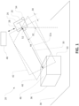
- FIG. 1 illustrates an example dimensioning system 20 according to an embodiment of the invention, in use to determine dimensions of an object 36.
- the object 36 is configured as a parallelepiped package with squared corners and edges (i.e., a generally rectangular prism shape).
- the dimensioning system 20 (or other embodiments of the invention) can be used to determine the dimensions of other types of objects, such as cylinders, pyramidal shapes, spherical shapes, and so on.
- the dimensioning system 20 (or other embodiments of the invention) can be used to determine the dimensions of moving objects. In some cases, this may be particularly feasible, as compared to prior art systems, due to the ability of the system 20 to determine object dimensions based on a single image and without necessarily requiring a particular location or orientation of the object. In some implementations, for example, an object on a parallel surface can be readily dimensioned regardless of the orientation of the object on the surface.
- a dimensioning system includes an imaging system with determined or controllable imaging parameters.
- the dimensioning system 20 includes an imaging system 24 with an optical arrangement that includes an imaging sensor 26, and a lens arrangement with a lens 28.
- the imaging system 24 defines imaging parameters that include: an angular orientation of an optical axis 30, such as specified by an angle 32 relative to a gravitational reference frame; a distance 34 along the optical axis 30 between the imaging sensor 26 and the lens 28; a field of view (“FOV”) that can include an object 36 on a flat support surface 38; and a pixel size of the imaging sensor 26.
- the imaging system 24 also defines a sagittal imaging plane 40 and a tangential imaging plane 42, coincident on the optical axis 30, and a distance 44 between the lens 28 and the object 36 along the optical axis 30.
- the angle 32 relative to gravity may be equivalent to an angle of the optical axis relative to a normal line extending from a particular facet of an object.
- the angle of the optical axis 30 relative to the support surface 38 may be the same as the angle of the optical axis 30 relative to a top horizontal facet 46 of the object 36.
- an orientation or geometry of an object or a support surface may alter this correspondence.
- a mathematical transform may be required to convert an angle of the optical axis relative to gravity (or another reference frame) to an angle relative to a reference frame of the object. In some embodiments, this transform may be based upon further analysis of the relevant object, such as machine vision analysis implemented by a machine vision system 48 to identify a particular aspect of the object.
- the machine vision system 48 can be included in the imaging system 24. In some embodiments, the machine vision system 48 can be remotely disposed and in electronic communication with the imaging system 24. In some embodiments, a processor device (not shown) for other operations described herein can be included in the imaging system 24, in the machine vision system 48, or in another system that is generally in communication with dimensioning system 20.
- the FOV of the imaging system 24 is oriented so that an image of the object 36, captured by the imaging sensor 26, includes the top facet 46 and a front facet 50 of the object 36 as intercepted by the sagittal and tangential imaging planes 40, 42. As detailed below, this may be useful in order to determine dimensions of the object 36 efficiently and accurately.
- imaging parameters may be predetermined and relatively unchangeable.
- the location and angular orientation of the imaging system 24 may be relatively permanent, and therefore may not change during relevant operations.
- certain imaging parameters may be changeable.
- some fixed-mount imaging systems may be adjustable in certain aspects.
- some imaging systems can be configured as mobile systems that may be subjected to changes in location and orientation during normal operation.
- values of the angle 32 and the distance 44 may sometimes change.
- at least the distance 44 may change over time.
- the distance 44 between the lens 28 and the object 36 may be predetermined
- the distance 44 may, for example, be retrieved from a look-up table or other repository. In some implementations, however, it may be appropriate to measure the distance 44 for a particular image acquired by the imaging system 24. To this end, it may be useful to include a distance sensor within the dimensioning system 20. In different embodiments, different types of distance sensors can be used, such as laser range finders, time of flight sensors, laser displacement or stereo displacement systems, and so on.
- a laser range finder may be optimally employed.
- laser range finders may be relatively inexpensive, durable, and reliable, and the expected accuracy may be appropriate for the purposes described herein.
- laser range finders may sometimes be configured to determine a distance only at a particular point (or relatively small area) on an object, this may not necessarily limit the utility of the measurement for many embodiments of the invention due to the nature of the dimensioning operations disclosed herein.
- a laser range finder 52 is mounted to the imaging system 24, so that the laser range finder 52 can generally determine a distance between the imaging system 24 and the object 36.
- the laser range finder 52 may not necessarily measure the distance 44 directly, due, for example, to the placement of the laser range finder 52 relative to the other components of the imaging system 24. But, in such a case, it may be relatively trivial to derive the distance 44 from the measured distance, based on predetermined relative spacings of the laser range finder 52 and the lens 28 (or other components of the imaging system 24).
- the laser range finder 52 can be mounted at other locations on the imaging system 24 without significant detriment to performance.
- a beam 52a of the laser range finder 52 may be useful to orient a beam 52a of the laser range finder 52 to travel in parallel with the optical axis 30, or along the sagittal imaging plane 40 (as shown) or the tangential imaging plane 42.
- the distance 44 can be relatively directly measured via operation of the laser range finder 52 and thereafter utilized to dimension the object 36 (e.g., as described below).
- a beam of a laser range finder may be configured to intersect an object separately from a relevant sagittal or tangential plane of the associated imaging system, or to travel obliquely to one or both of those planes.
- the value of a relevant distance (e.g., the distance 44) may still be derived with relatively low-cost computational efforts.
- the distance can be derived based upon a predetermined angular orientation of the relevant range finding device (e.g., an angle of a laser range finder relative to an optical axis) or other factors.
- the incidence of a beam of a laser range finder (or other similar device) on an object can be identified within an image of the object in order to inform appropriate adjustment of the distance by the range finder and thereby to appropriately determine a distance to the object to use during object dimensioning.
- known trigonometric principles can be applied with relatively little computational expense, in order to provide an appropriate distance between an object and a lens of an imaging system.
- a look-up table or relevant trigonometric equations can be stored in an imaging system (or elsewhere) to assist in identifying an expected incidence on an object of the beam of a laser range finder, depending on the distance between the imaging system 24 and the object or other factors.
- the angle 32 of the optical axis 30 may be predetermined and may, for example, be retrieved from a look-up table or other repository.
- the imaging system 24 is a fixed-mount imaging system
- the physical support structures and mounting apparatus that support the imaging system 24 may relatively fixedly determine the angle 32 relative to a particular reference frame (e.g., as based on gravity or the support surface 38).
- an accelerometer such as a three-axis linear accelerometer 54
- the imaging system 24 can be associated with the imaging system 24, in order to measure the orientation of the imaging system 24 and thereby, directly or indirectly, to measure the value of the angle 32.
- an embedded accelerometer can be employed.
- other devices can be similarly used, such as three-axis gyroscopes, or other angular measurement devices.
- dimensions of various objects can then be calculated with relatively high efficiency and accuracy.
- an image of the object 36 can be acquired using the imaging sensor 26 and one or more features of the object 36, such as points along the facets 46, 50, can be identified within the image.
- Dimensions of the object 36 can then be determined from the image, using imaging parameters of the imaging system 24, such as those described above. For example, as also described below, a trigonometric relationship can be identified and then solved based upon known aspects of the imaging system 24 in combination with at least the object-lens distance 44, the optical-axis angle 32, and the identified object features.
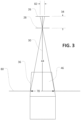
- FIG. 2 An example implementation of these principles is illustrated in a simplified schematic in FIG. 2 .
- an image of the object 36 has been captured using the imaging system 24, with the representation of the object 36 within the image resulting from light incident over a combination of distances 60, 62 on the imaging sensor 26.
- the image includes a representation of a full depth 64 of the top facet 46 and a representation of a full height 66 of the front facet 50, which can be viewed as being virtually projected as distances 68, 70, respectively, on a virtual object plane 72.
- front and rear edges of the facet 46 and top and bottom edges of the facet 50 have been identified within the image (e.g., as described below), so that virtual light paths between these edges and the imaging sensor 26 can be identified (as illustrated in FIG. 2 ).
- the value of the angle 32, the distance 44, and the distance 34 may be known or may be readily determined, as may a correspondence between a pixel of an image and an associated distance along the imaging sensor 26. Accordingly, using known trigonometric relationships, relatively low-cost computer calculations can be implemented to determine the actual value of the depth and height 64, 66 of the object 36. In some implementations, for example, pixel counts corresponding to the distances 60, 62 can be determined. Then the values of the distances 68, 70, angles 74, 76, and distances 68, 70 can also be determined, based on the distances 60, 62, the distances 34, 44, and the angle 32. In this way, for example, dimensions of triangles including the depth and height 64, 66 of the object 36 can be fully specified, so that the values of the depth and height 64, 66 can be fully determined.
- a width 82 on the imaging sensor 26 that receives light rays from the width 78 of the facet 46 can be derived from a pixel width of the facet 46 in the image, as similarly described above. Based on the known distances 34, 44, the value of the width 78 can then be readily determined by solving the associated trigonometric relationships.
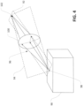
- FIGS. 2 and 3 illustrate an example in which the object 36 is a parallelepiped that is oriented squarely relative to the imaging sensor 26.
- this configuration may not be possible.
- an object 90 may be imaged such that a sagittal imaging plane 92 and a tangential imaging plane 94 are somewhat skewed relative to the square dimensions of the object 90.
- light rays 96 from an object point 98 though a lens 100 to a corresponding image point 102 similar trigonometric relationships as those described above may still apply. Accordingly, similar determination of the dimensions of the object 90 can be executed, supplemented as appropriate with rotational transformations.
- the points of the object 36 that were identified within the acquired image to assist in determining the values of the depth and height 64, 66 correspond to line segments along opposing edges of the facets 46, 50. Further, a subset of points used to determine each the depth and height 64, 66 overlap along the shared edge of the facets 46, 50. In other implementations, non-edge and nonoverlapping points can be selected. Similarly, in some cases points along non-opposing line segments or edges, or points not on adjacent facets, can be selected
- features of an object within an image can be identified in different ways.
- a machine vision system can be used, such as the system 48 illustrated in FIG. 1 .
- known machine vision algorithms can be used to identify an intensity edge or an intensity corner of an image in order to identify a corresponding edge, corner, facet, or other feature of an object to be dimensioned. Dimensioning of the object can then proceed, for example, similarly to the approach detailed with regard to FIGS. 2 and 3 .
- a machine vision system such as the system 48, can be used to identify multiple features on an object, such as at least three edges or at least one edge and two corners.
- a machine vision system can be used to detect at least three intensity edges, or one intensity edge and two intensity corners, respectively, within the relevant image.
- a dimensioning system can be configured to receive user input in order to identify object features within an image.
- a user interface can be configured to receive input from a user that directly identifies an edge, corner, facet or other feature within an image, to assist in determining dimensions of a corresponding object.
- a dimensioning system can include a touchscreen or other similar input device to receive tactile (or other) input from a user, in order to identify particular features of an object within an image of the object.
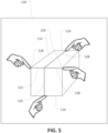
- an example dimensioning system can include a touchscreen 110 that is configured to display an image of an object 112 and to receive tactile input from a user.
- a user has touched the touchscreen 110 at a set of four points that correspond to two edges 114, 116 that lie at opposite ends of adjacent facets of the object 112, and two corners 118, 120 of an edge 122 that lies at a junction between the adjacent facets.
- user input can appropriately specify a sufficient number of features in the image of the object 112 so that values of a height 124, width 126, and depth 128 of the object 112 can be determined.
- Tactile-input (or other similar) implementations may be particularly useful with mobile systems, and can support dimensioning operations with errors of less than 5%. It may also be possible, however, to effect similar implementations in fixed-location systems with appropriate input interfaces.
- a dimensioning system can utilize machine learning algorithms (or resulting look-up tables) to identify features on objects, including edges, corners, or facets of parallelepiped boxes.
- known machine vision tools for identifying lines can be used. For example, a Hough transform or other machine vision algorithm can be employed in order to identify line candidates. In some embodiments, further refinement may then be necessary in order to distinguish likely edges of an object from irrelevant line candidates, such as may result from support structures, creases or markings on an object, lighting irregularities, and so on. Again, a variety of machine vision algorithms or other approaches can be used in this regard.
- a user input, a calibration setting, or another factor can be used to determine an expected angle of a line, and candidate lines in an image, such as lines that may represent object edges, can be identified accordingly. For example, based on the expected geometry of an object and a known (e.g., measured) orientation of an imaging device, the relative expected angle in an image of vertical and horizontal edges of the object can be determined. A search for line candidates in the image can then be constrained accordingly. For example, as illustrated in FIG 6 , sets of candidate horizontal lines 130 and candidate vertical lines 132 can be identified for a particular object 134 based on the expected angular orientation of the edges of the object 134.
- candidate horizontal lines can be identified based upon an expected orientation of an object within an image.
- the upper line 130 in FIG. 6 can be identified based on pre-determining that an uppermost line (or lines) in an image is likely to correspond to a top, far edge of the object 134.
- the lower line 130 in FIG. 6 can be identified based on pre-determining that a lower-most line (or lines) in an image is likely to correspond to a bottom, near edge of the object.
- candidate lines can be identified based upon an expectation that an aimer for imaging (e.g., as described relative to FIG. 8 , below) may be aimed at a particular portion of an object. For example, based upon an expectation that a laser aimer (see, e.g., FIG. 8 ) is aimed at a top, front edge of a parallelepiped, a system can be configured to identify, as a candidate for a top, front edge, particular lines in an image that are relatively close to an identified location of an aimer pattern.
- detailed orientation information for an imaging device can be used to identify or refine sets of line candidates in an image.
- a mobile imaging device e.g., as described relative to FIGS. 7 and 8 , below
- an accelerometer that can provide three-axis (or other) orientation information.
- it may be possible to determine an angle of an optical axis e.g., similar to the angle 32 of FIGS. 1 and 2 ), which may be characterized as a "pitch" of the relevant system.
- this additional information regarding orientation can be used to refine analysis of an image to identify or refine line candidates.
- the yaw and roll of an imaging system may be used to identify likely orientation of horizontal and vertical (or other) edges of an object in an acquired image.
- line candidates can be considered in combination with each other in order to identify likely edges or other features of an object.
- the general geometric patterns of an object can be determined, such as the expected number and relative orientation of edges of a parallelepiped.
- Sets of candidate lines can then be analyzed in order to emphasize sets of lines that correspond to that number and relative orientation or to reject sets of lines that do not.
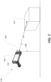
- FIG. 7 illustrates a mobile dimensioning system 140 that includes a mobile device 142 (e.g., a smartphone) that is supported in a portable pistol-grip housing 144.
- the mobile device 142 generally includes an imaging sensor, a lens arrangement, and an angular sensor (e.g., a three-axis accelerometer) configured to measure an angle 146 of the mobile device 142 relative to gravity (or another reference frame).
- the housing 144 also supports a range finder 148 (e.g., a laser range finder) that exhibits a predetermined orientation relative to the imaging sensor of the mobile device 142 and is configured to measure a distance 150 between the mobile device 142 and an object 152 to be imaged.
- a range finder 148 e.g., a laser range finder
- the mobile dimensioning system 140 can be used to determine dimensions using operations consistent with other discussion herein.
- a touchscreen of the mobile device 142 can be used to identify features of the object 152 in an acquired image and then dimensions of the object 152 can be determined from the image using operations similar to those discussed with regard to FIGS. 2 through 4 .
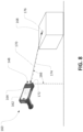
- FIG. 8 illustrates a mobile dimensioning system 160.
- the mobile dimensioning system 160 is generally similar to the mobile dimensioning system 140 of FIG. 7 and, accordingly, includes a mobile device 162, such as a smartphone with a three-axis accelerometer, that is supported in a portable pistol-grip housing 164.
- the mobile dimensioning system 160 can measure an angle 166 of the mobile device relative to gravity (or another reference frame) using the included accelerometer or other similar device.
- the mobile dimensioning system 140 can determine relevant dimensions of the object 168 (e.g., using operations as discussed in detail above).
- the housing 164 supports an aimer 172 to assist in acquiring images of the object 168.
- projected illumination from the aimer 172 can be used to determine the distance 170, in support of dimensioning operations.
- the aimer 172 is an off-axis spot aimer, which projects an aiming beam along a direction 174 to illuminate an aiming pattern, such as an aimer dot 176, on the object 168.
- the off-axis configuration of the aimer 172 causes the aiming beam to be projected obliquely (e.g., nearly, but not fully, parallel) relative to the optical axis of the imaging device of the system 160, such as may be represented in FIG. 8 by the line indicating the distance 170.
- the position of the aimer dot 176 on the object 168, relative to a center of an image of the object 168 acquired by the mobile device 162 may vary depending on the distance between the aimer 172 and the object 168.
- the position of the aimer dot 176 in an image of the object 168 can accordingly be used to determine the distance 170, in support of further dimensioning operations.
- calibrated tables or predetermined relationships between aimer-dot location and object distance can be used to determine the distance 170.
- a mathematical model can be derived to determine distance to an object based upon displacement of an aimer pattern in an image relative to a location of the aimer pattern in an image that was acquired with the object at a known length. For example, if the precise location of an optical center in an image (i.e., a point in the image corresponding to the optical axis) is known, the location of the aimer pattern can be determined with the object at three or more different calibration locations that exhibit known object-imaging distances. A relationship can then be determined between the distance to an object and the distance of the aimer pattern from the optical center of an image. As another example, if the precise location of an optical center is not known, a similar relationship can be determined based upon capture and analysis of calibration images with the object at four or more different locations that exhibit known object-imaging distances.
- some approaches to calibration can be used to create a relatively detailed look-up table that relates locations of aimer patterns in images to distances of the object from the aimer or an associated imaging system. For example, a plurality of images can be acquired of an aimer pattern on an object at a plurality of known distances from the imaging device. During run-time operations, the identified location of an aimer pattern in an image can then be compared to locations in the look-up table and an approximate distance to the object determined accordingly.
- a dimensioning system may be configured to execute particular types of image analysis.
- the mobile device 162 of the mobile dimensioning system 160 can be configured to use (or call) a blob or other thresholding tool to identify an aimer pattern.
- a blob or other thresholding tool to identify an aimer pattern.
- a search area for an aimer pattern in an image can be constrained based on an expected behavior of the aimer pattern upon changes in the object-imaging distance.
- the aimer pattern may be expected to move (in associated images) along a generally straight line as the aimer (and imaging device) move towards or away from an object.
- a search routine to identify the aimer pattern can be constrained to a line or rectangle within an image.
- the aiming patter is configured as the aimer dot 176, which is generally circular (or, e.g., ovular, depending on the surface onto which it is projected).
- the aimer dot 176 is generally circular (or, e.g., ovular, depending on the surface onto which it is projected).
- other configurations are possible.
- other patterns of aimer light can be used, with mobile dimensioning systems configured to identify particular (e.g., distinctive) features of the patterns in acquired images.
- a dimensioning system can be configured to determine dimensions of an object in other ways.
- a dimensioning system can be arranged with an optical axis that is perpendicular to a relevant surface and geometric relationships dependent on that perpendicular arrangement can be used to determine object dimensions.
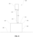
- FIG. 9 illustrates a dimensioning system 180 that includes an imaging system 182 with an optical axis 184 that is substantially perpendicular to a support surface, such as a conveyor 186 configured to move the object 188.
- the imaging system 182 can be configured as a mobile system, such as a system similar to the mobile device 142 of FIG. 7 , or as a fixed system, such as a system similar to the imaging system 24 of FIG. 1 .
- the imaging system 182 can include appropriate lens arrangements (not shown in FIG. 9 ), processing devices (not shown in FIG. 9 ), or communication links (not shown in FIG. 9 ).
- the range finder 190 includes an off-axis aimer similar to the aimer 172 of FIG. 8 . Accordingly, the distance 192 can be determined using operations similar to those described with respect to FIG. 8 . For example, the distance 192 can be determined based upon locating an aiming pattern (not shown in FIG. 9 ) of the aimer 172 in an image of the object 188 that is acquired by the imaging system 182.
- the range finder 190 can be configured as a laser range finder, a time of flight sensor, a laser displacement or stereo displacement system, and so on.
- the dimensioning system 180 can identify features of the object 188 in an image acquired by the imaging system 182. For example, features of a top surface of the object 188 (relative to the illustrated perspective of FIG. 9 ), such as an edge 194, corners 196, and so on, can be identified, as similarly described above, using machine vision operations, based upon user input, or in other ways.
- a height of the object 188 above the conveyor 186 can then be calculated based on a difference between the distance 192 and a total distance between the imaging system 182 and the conveyor 186, with the total distance between the imaging system 182 and the conveyor 186 having been determined based upon manual input, prior or subsequent measurement using the ranger finder 190, or in other ways.
- the dimensions (e.g., length and width) of the top surface of the object 188 can be determined using operations similar to those described above, as applied to the identified features of the object 188 in a relevant image and based upon the determined distance 192 and known properties of the imaging system 182. In this way, for example, a full set of dimensions for the object 188 can be determined based upon acquisition of a single image (or more) of the object 188 by the imaging system 182.
- an embodiment of the invention can include computer-implemented methods, including methods executed by software or hardware modules of dimensioning or other (e.g., general machine-vision) systems.
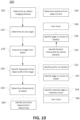
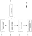
- an embodiment of the invention can include a method 200 for determining dimensions of an object.
- operations of the method 200 can be executed by the dimensioning systems 20, 180 of FIGS. 1 and 9 or the mobile dimensioning systems 140, 160 of FIGS. 7 and 8 .
- other dimensioning systems can be used.
- the method 200 includes determining 202 an object-imaging distance as a distance between an object to be imaged and a part of an imaging system.
- determining 202 the object-imaging distance may include directly determining a first distance and then deriving the object-imaging distance from the first distance. For example, using a laser range finder or other device, a distance can be determined 204 between the object and a housing of an imaging system, and then predetermined spatial aspects of the imaging system used to derive a distance between the object and a relevant lens (or other component).
- the method 200 also includes determining 210 an axis angle as an angle of an optical axis of the imaging system relative to a particular reference. For example, using an accelerometer or a predetermined angular aspect of a fixed support structure, an angle of an optical axis relative to gravity or to a relevant support surface can be determined 210. In some implementations an axis angle may be determined 210 directly. In some implementations, an axis angle may be determined 210 indirectly. For example, a different angle may first be determined and then the axis angle derived therefrom.
- the method 200 also includes acquiring 220 an image of the object using the imaging system.
- an image can be acquired 220 before, after, or simultaneously with the determination 202 of a relevant object-imaging distance and the determination 210 of a relevant axis angle.
- the method 200 also includes identifying 230 one or more features of the object within the acquired image.
- features can be identified 230 in different ways. For example, in some embodiments, multiple points can be identified 232 on facets of the object (within the image) based upon identifying 234 facets that are intersected by sagittal and tangential imaging planes and then identifying 236 edges, corners, or other features of those facets (e.g., opposing or shared edges or corners).
- user input 240 such as input received at a touchscreen can be used to identify 234 the facets or to identify 236 edges, corners, or other features thereof.
- edges or corners of an object can be identified 242 based upon identifying 244 intensity edges or intensity corners within an image. For example, based upon user input 246 or machine vision algorithms, intensity edges or intensity corners can be identified 244 in a particular image and the locations of the intensity edges or intensity corners can be thereupon identified 242 as corresponding
- the method 200 also includes determining 250 one or more of the dimensions of the object. For example, according to principles described above, trigonometric relationships can be identified and then solved 260 based upon predetermined imaging parameters (e.g., sensor-lens distance), measured parameters (e.g., object-lens distance and axis angle), and various identified 230 features of the object. As also noted above, different approaches to identifying and solving 260 the trigonometric relationships are possible, including those specifically described with regard to FIGS. 2 through 4 , above.
- an object-imaging distance can be determined using an aimer, such as an off-axis aimer included in a mobile dimensioning system.
- determining an object-imaging distance can be based upon projecting 270 an illuminated feature onto an object.
- an aimer patter can be projected 270 onto an object by an off-axis aimer 272 of a mobile (or other) dimensioning system.
- the illuminated feature can then be identified 280 in the image and an object-imaging distance can be determined 202 on that basis.
- the object-imaging distance can be determined 202 based upon identifying 290, in the image, a displacement of the projected 270 (and identified 280) illuminated feature relative to the location of the relevant optical axis.
- embodiments of the invention can provide improved systems and methods for determining dimensions of an object.
- use of a combination of predetermined and measured parameters can allow for improved operation of dimensioning systems, including through determination of object dimensions with relatively high accuracy, efficiency and speed, as compared to conventional systems.
- dimensioning systems according to the invention can allow dimensions of an object to be determined without requiring the use of structure light, the capture of high-focus images, the close control of ambient lighting or other imaging conditions, or the capture of multiple images.
Landscapes
- Engineering & Computer Science (AREA)
- Physics & Mathematics (AREA)
- General Physics & Mathematics (AREA)
- Theoretical Computer Science (AREA)
- Computer Vision & Pattern Recognition (AREA)
- General Engineering & Computer Science (AREA)
- Geometry (AREA)
- Human Computer Interaction (AREA)
- Optics & Photonics (AREA)
- Quality & Reliability (AREA)
- Length Measuring Devices By Optical Means (AREA)
Claims (15)
- System (20) zur Bestimmung von Dimensionen eines Objekts (36), wobei das System Folgendes umfasst:
ein Bilderfassungssystem (24), das Folgendes umfasst:einen Bildsensor (26); undeine Linsenanordnung, die eine Linse (28) umfasst und eine optische Achse (30), ein Sichtfeld, das zumindest teilweise das Objekt umfasst, und einen Sensor-Linse-Abstand (34) zwischen dem Bildsensor (26) und der Linse (28) definiert, undeine Prozessorvorrichtung, die dazu ausgebildet ist,einen Objekt-Bilderfassung-Abstand (44) als einen Abstand zwischen dem Objekt und der Linsenanordnung basierend auf einem Abruf aus einer Nachschlagetabelle oder Messung durch einen Abstandssensor zu bestimmen;einen Achsenwinkel (32) als einen Winkel der optischen Achse relativ zu einem Bezugssystem basierend auf einem Abruf aus einer Nachschlagetabelle oder Messung durch einen Winkelmesssensor zu bestimmen;ein Bild des Objekts (36) unter Verwendung des Bildsensors (26) aufzunehmen;ein oder mehrere Merkmale (46, 50) des Objekts (36) in dem Bild zu identifizieren; undeine oder mehrere der Dimensionen (64, 66) des Objekts (36) basierend auf mindestens dem Objekt-Bilderfassung-Abstand (44), dem Achsenwinkel (32) und den einen oder mehreren identifizierten Merkmalen (46, 50) des Objekts zu bestimmen. - System nach Anspruch 1, wobei das Bilderfassungssystem eines von Folgenden ist:ein ortsfestes Bilderfassungssystem mit dem Objekt-Bilderfassung-Abstand (44) und dem Achsenwinkel (32), der durch ein bauliches Stützsystem für das Bilderfassungssystem festgelegt ist; oderein Mobiltelefon, das mit einem Entfernungsmesser (52; 176; 190) verbunden ist, wobei der Entfernungsmesser dazu ausgebildet ist, einen Abstand zu dem Objekt zu messen, um den Objekt-Bilderfassung-Abstand (44) zu bestimmen.
- System nach Anspruch 2, wobei der Entfernungsmesser eine außeraxiale Zielvorrichtung (172) umfasst; und
wobei die Prozessorvorrichtung des Weiteren dazu ausgebildet ist, den Objekt-Bilderfassung-Abstand (44) basierend auf der Identifikation eines von der außeraxialen Zielvorrichtung (172) bereitgestellten beleuchteten Merkmals (176) in dem Bild des Objekts zu bestimmen. - System nach Anspruch 1, wobei die Identifikation des einen oder der mehreren Merkmale des Objekts in dem Bild Folgendes umfasst:
eine Identifikation einer Vielzahl von Rändern des Objekts in dem Bild basierend auf einem oder mehreren Schritten von folgenden Schritten:Identifizieren einer oder mehrerer am weitesten entfernter Linien (130, 132) auf einer oder mehreren Seiten eines erwarteten geometrischen Profils des Objekts (134);Identifizieren mindestens einer Linie (130, 132), die sich unmittelbar an dem identifizierten Merkmal befindet; oderIdentifizieren eines Satzes Kandidaten-Linien (130, 132) basierend auf dem erwarteten geometrischen Profil des Objekts; undIdentifizieren einer erwarteten Linienausrichtung basierend auf einem Ausrichtungssensor (54), der dem Bildsensor zugeordnet ist. - Verfahren (200) zur Bestimmung von Dimensionen eines Objekts (36), für die Verwendung mit einem Bilderfassungssystem (20), das eine optische Anordnung mit einem Bildsensor (26), eine Linsenanordnung, die eine optische Achse (30) und ein Sichtfeld, das zumindest teilweise das Objekt (36) umfasst, definiert, und einen Sensor-Linse-Abstand (34) zwischen dem Bildsensor (26) und einer Fokussierlinse (28) der Linsenanordnung umfasst; wobei das Verfahren zumindest teilweise unter Verwendung einer Prozessorvorrichtung durchgeführt wird und folgende Schritte umfasst:Bestimmen (202) eines Objekt-Bilderfassung-Abstands (44) als einen Abstand zwischen dem Objekt und der Linsenanordnung basierend auf einem Abruf aus einer Nachschlagetabelle oder Messung durch einen Abstandssensor;Bestimmen (210) eines Achsenwinkels (32) als einen Winkel der optischen Achse relativ zu einem Bezugssystem basierend auf einem Abruf aus einer Nachschlagetabelle oder Messung durch einen Winkelmesssensor;Aufnehmen (220) eines Bildes des Objekts (36) unter Verwendung des Bilderfassungssystems;Identifizieren (230) eines oder mehrerer Merkmale des Objekts in dem Bild unter Verwendung der Prozessorvorrichtung; undBestimmen (250) einer oder mehrerer der Dimensionen des Objekts unter Verwendung der Prozessorvorrichtung basierend auf mindestens dem Objekt-Bilderfassung-Abstand, dem Achsenwinkel und den einen oder mehreren identifizierten Merkmalen des Objekts.
- Verfahren nach Anspruch 5, wobei das Bestimmen (202) des Objekt-Bilderfassung-Abstands auf dem Bestimmen (204) eines Abstands zwischen dem Objekt und der Fokussierlinse basiert.
- Verfahren nach Anspruch 5, wobei das Objekt ein Parallelepiped ist und wobei optional oder vorzugsweise das Parallelepiped eine rechteckige Box ist und die eine oder mehreren bestimmten (250) Dimensionen eine Höhe der rechteckigen Box und/oder eine Breite der rechteckigen Box und/oder eine Tiefe der rechteckigen Box umfassen.
- Verfahren nach Anspruch 5, wobei das Identifizieren (230) des einen oder der mehreren Merkmale das Identifizieren (232) eines oder mehrerer Punkte auf einer ersten Fläche (50) des Objekts und eines oder mehrerer Punkte auf einer zweiten Fläche (46) des Objekts, die benachbart der ersten Fläche ist, umfasst.
- Verfahren nach Anspruch 8, wobei das Bilderfassungssystem eine sagittale optische Ebene (40) und eine tangentiale optische Ebene (42) definiert, wobei das Objekt so positioniert ist, dass die erste Fläche (50) von der sagittalen optischen Ebene (40) und die erste und zweite Fläche (50, 46) von der tangentialen optischen Ebene (42) durchschnitten werden.
- Verfahren nach Anspruch 9, wobei der eine oder die mehreren Punkte auf der ersten Fläche einen ersten Punkt auf einem Liniensegment (122) an einer Schnittstelle der ersten und der zweiten Fläche umfassen und ein oder mehrere Punkte auf der zweiten Fläche einen zweiten Punkt auf dem Liniensegment (122) an der Schnittstelle der ersten und der zweiten Fläche umfassen und wobei optional oder vorzugsweise der eine oder die mehreren Punkte auf der ersten Fläche einen dritten Punkt an einem Rand (114) der ersten Fläche umfassen, der dem Liniensegment an der Schnittstelle der ersten und der zweiten Fläche gegenüberliegt; und wobei der eine oder die mehreren Punkte auf der zweiten Fläche einen vierten Punkt auf einem Rand (116) der zweiten Fläche umfassen, der dem Liniensegment an der Schnittstelle der ersten und der zweiten Fläche gegenüberliegt.
- Verfahren nach Anspruch 8, wobei der eine oder die mehreren Punkte entlang eines Rands (122) des Objekts zwischen benachbarten Flächen des Objekts und/oder an einer Ecke (118, 120) an einer Schnittstelle von mehreren Flächen des Objekts angeordnet sind und wobei das Verfahren des Weiteren optional oder vorzugsweise das Identifizieren des Rands und/oder der Ecke unter Verwendung eines Machine-Vision-Systems basierend auf dem Erfassen eines Intensitätsrands bzw. einer Intensitätsecke in dem Bild umfasst.
- Verfahren nach Anspruch 5, wobei das Identifizieren (230) des einen oder der mehreren Merkmale des Objekts in dem Bild auf dem Empfangen einer Benutzereingabe (240) an einer Computerschnittstelle basiert, wobei die Benutzereingabe (240) eine Position des einen oder der mehreren Merkmale des Objekts auf einer Darstellung des Bildes an der Computerschnittstelle identifiziert.
- Verfahren nach Anspruch 5, wobei der Objekt-Bilderfassung-Abstand basierend auf folgenden Schritten bestimmt (202) wird:Projizieren (270) eines beleuchteten Merkmals auf das Objekt; undIdentifizieren (280) des beleuchteten Merkmals in dem Bild.
- Verfahren nach Anspruch 5, wobei das Bilderfassungssystem zum Bestimmen (202) des Objekt-Bilderfassung-Abstands Folgendes umfasst:
einen Laserentfernungsmesser (148), wobei das Bestimmen (202) des Objekt-Bilderfassung-Abstands unter Verwendung der Prozessorvorrichtung auf dem Empfangen von Signalen aus dem Laserentfernungsmesser basiert; und/oder eine außeraxiale Zielvorrichtung (172), wobei das Bestimmen (202) des Objekt-Bilderfassung-Abstands auf dem Identifizieren eines beleuchteten Merkmals aus der außeraxialen Zielvorrichtung in dem Bild unter Verwendung der Prozessorvorrichtung basiert. - System (20) nach einem der Ansprüche 1 bis 4, wobei das System als ein mobiles System (140; 160) zur Bestimmung von Dimensionen des Objekts (36) ausgebildet ist, wobei das mobile System Folgendes umfasst:ein mobiles Gehäuse (144; 164), das den Bildsensor (26) stützt, die Linsenanordnung, einen Entfernungsmesser (148), der zum Messen eines Abstands zu dem Objekt ausgebildet ist, einen Winkelsensor, der zum Messen einer räumlichen Ausrichtung des mobilen Systems ausgebildet ist und die Prozessorvorrichtung;wobei die Prozessorvorrichtung dazu ausgebildet ist,den Objekt-Bilderfassung-Abstand (44) basierend auf dem durch den Entfernungsmesser (148) gemessenen Abstand zu bestimmen;den Achsenwinkel (32) basierend auf der durch den Winkelmesssensor gemessenen räumlichen Ausrichtung zu bestimmen; unddas eine oder die mehreren Merkmale des Objekts (36) in dem Bild auf der Basis von Folgendem zu identifizieren:Verwenden eines Machine-Vision-Systems zum Identifizieren eines Merkmals von einem Rand und/oder einer Ecke und/oder einer Fläche des Objekts in dem Bild;
und/oderEmpfangen einer Benutzereingabe auf einem Touchscreen des mobilen Systems,die einem Rand und/oder einer Ecke und/oder einer Fläche des Objekts in dem Bild identifiziert.
Applications Claiming Priority (2)
| Application Number | Priority Date | Filing Date | Title |
|---|---|---|---|
| US16/259,761 US10937183B2 (en) | 2019-01-28 | 2019-01-28 | Object dimensioning system and method |
| PCT/US2020/015203 WO2020159866A1 (en) | 2019-01-28 | 2020-01-27 | Object dimensioning system and method |
Publications (3)
| Publication Number | Publication Date |
|---|---|
| EP3918274A1 EP3918274A1 (de) | 2021-12-08 |
| EP3918274A4 EP3918274A4 (de) | 2022-11-02 |
| EP3918274B1 true EP3918274B1 (de) | 2024-08-21 |
Family
ID=71732709
Family Applications (1)
| Application Number | Title | Priority Date | Filing Date |
|---|---|---|---|
| EP20748194.6A Active EP3918274B1 (de) | 2019-01-28 | 2020-01-27 | Objektdimensionierungssystem und -verfahren |
Country Status (3)
| Country | Link |
|---|---|
| US (1) | US10937183B2 (de) |
| EP (1) | EP3918274B1 (de) |
| WO (1) | WO2020159866A1 (de) |
Families Citing this family (9)
| Publication number | Priority date | Publication date | Assignee | Title |
|---|---|---|---|---|
| ES2826476T3 (es) * | 2014-05-15 | 2021-05-18 | Federal Express Corp | Dispositivos portátiles para el procesamiento de mensajería y métodos de uso de los mismos |
| JP6923574B2 (ja) * | 2019-02-01 | 2021-08-18 | ファナック株式会社 | 3次元形状計測システムおよび3次元形状計測方法 |
| US11776153B2 (en) * | 2019-10-08 | 2023-10-03 | Zebra Technologies Corporation | Method, system and apparatus for mobile dimensioning |
| CH718308B1 (fr) * | 2019-12-11 | 2024-04-30 | Chugai Pharmaceutical Co Ltd | Dispositif d'alimentation en pièces et système de transfert de pièce. |
| US12026912B2 (en) * | 2021-09-13 | 2024-07-02 | Wen Li | Apparatus and methodology for aiming point and aiming device 6DOF detection using image registration |
| TWI772184B (zh) * | 2021-09-16 | 2022-07-21 | 友達光電股份有限公司 | 顯示系統及控制方法 |
| US11909950B1 (en) * | 2021-09-21 | 2024-02-20 | Amazon Technologies, Inc. | Three-dimensional (3D) sensor performance evaluation |
| US12073284B2 (en) * | 2022-06-15 | 2024-08-27 | Hand Held Products, Inc. | Calibration for scanning device decoding based on aimer pattern detection |
| EP4386439A1 (de) | 2022-12-15 | 2024-06-19 | Mettler-Toledo GmbH | Verfahren zur diagnose einer änderung der ausrichtung einer laserentfernungsmessereinheit und laserentfernungsmessereinheit und system zur durchführung des verfahrens |
Family Cites Families (26)
| Publication number | Priority date | Publication date | Assignee | Title |
|---|---|---|---|---|
| US5699161A (en) | 1995-07-26 | 1997-12-16 | Psc, Inc. | Method and apparatus for measuring dimensions of objects on a conveyor |
| TW327700B (en) * | 1997-07-15 | 1998-03-01 | Mos Electronics Taiwan Inc | The method for using rough oxide mask to form isolating field oxide |
| EP0913707B1 (de) | 1997-10-31 | 2003-06-11 | LAP GmbH Laser Applikationen | Verfahren zur berührungsfreien Messung des Abstands eines Objekts nach dem Prinzip der Laser-Triangulation |
| US6795200B1 (en) | 2000-11-13 | 2004-09-21 | Point Grey Research Inc. | Method and system for dimensioning boxes or other cuboid objects |
| KR100422370B1 (ko) | 2000-12-27 | 2004-03-18 | 한국전자통신연구원 | 3차원 물체 부피계측시스템 및 방법 |
| JP3624353B2 (ja) | 2002-11-14 | 2005-03-02 | 有限会社テクノドリーム二十一 | 3次元形状計測方法およびその装置 |
| WO2007033702A1 (de) | 2005-09-19 | 2007-03-29 | Gutehoffnungshütte Radsatz Gmbh | Verfahren zur berührungslosen dynamischen erfassung des profils eines festkörpers |
| US20090323084A1 (en) | 2008-06-25 | 2009-12-31 | Joseph Christen Dunn | Package dimensioner and reader |
| US9285840B2 (en) * | 2010-08-19 | 2016-03-15 | Michael S. Stamer | Detachable sensory-interface device for a wireless personal communication device and method |
| WO2013026180A1 (en) | 2011-08-23 | 2013-02-28 | Metrologic Instruments, Inc. | Optical code symbol reading system employing axicon-generated laser aiming beam |
| US9027838B2 (en) * | 2012-02-06 | 2015-05-12 | Cognex Corporation | System and method for expansion of field of view in a vision system |
| US9779546B2 (en) | 2012-05-04 | 2017-10-03 | Intermec Ip Corp. | Volume dimensioning systems and methods |
| WO2013170260A1 (en) | 2012-05-11 | 2013-11-14 | Proiam, Llc | Hand held dimension capture apparatus, system, and method |
| US9286530B2 (en) | 2012-07-17 | 2016-03-15 | Cognex Corporation | Handheld apparatus for quantifying component features |
| US9939259B2 (en) | 2012-10-04 | 2018-04-10 | Hand Held Products, Inc. | Measuring object dimensions using mobile computer |
| US20140104413A1 (en) | 2012-10-16 | 2014-04-17 | Hand Held Products, Inc. | Integrated dimensioning and weighing system |
| US9239950B2 (en) | 2013-07-01 | 2016-01-19 | Hand Held Products, Inc. | Dimensioning system |
| US9464885B2 (en) | 2013-08-30 | 2016-10-11 | Hand Held Products, Inc. | System and method for package dimensioning |
| US10229303B2 (en) | 2013-12-20 | 2019-03-12 | Cognex Corporation | Image module including mounting and decoder for mobile devices |
| US20160044301A1 (en) | 2014-08-06 | 2016-02-11 | Dejan JOVANOVICH | 3d modeling of imaged objects using camera position and pose to obtain accuracy with reduced processing requirements |
| KR20160027852A (ko) * | 2014-09-02 | 2016-03-10 | 삼성전기주식회사 | 렌즈의 틸트각 측정 및 보정 시스템 및 그 방법 |
| US9897434B2 (en) | 2014-10-21 | 2018-02-20 | Hand Held Products, Inc. | Handheld dimensioning system with measurement-conformance feedback |
| US10094650B2 (en) | 2015-07-16 | 2018-10-09 | Hand Held Products, Inc. | Dimensioning and imaging items |
| CN108351201B (zh) * | 2015-11-27 | 2020-02-21 | 富士胶片株式会社 | 物体测定装置及物体测定方法 |
| US20180108136A1 (en) * | 2016-10-18 | 2018-04-19 | Ortery Technologies, Inc. | Method of length measurement for 2d photography |
| US10375374B2 (en) * | 2017-03-29 | 2019-08-06 | Plethron Inc. | Dimension extractable object comprising spatial metadata for a captured image or video |
-
2019
- 2019-01-28 US US16/259,761 patent/US10937183B2/en active Active
-
2020
- 2020-01-27 WO PCT/US2020/015203 patent/WO2020159866A1/en not_active Ceased
- 2020-01-27 EP EP20748194.6A patent/EP3918274B1/de active Active
Also Published As
| Publication number | Publication date |
|---|---|
| WO2020159866A1 (en) | 2020-08-06 |
| US20200242793A1 (en) | 2020-07-30 |
| EP3918274A4 (de) | 2022-11-02 |
| US10937183B2 (en) | 2021-03-02 |
| EP3918274A1 (de) | 2021-12-08 |
Similar Documents
| Publication | Publication Date | Title |
|---|---|---|
| EP3918274B1 (de) | Objektdimensionierungssystem und -verfahren | |
| US11511421B2 (en) | Object recognition processing apparatus and method, and object picking apparatus and method | |
| US11320833B2 (en) | Data processing method, apparatus and terminal | |
| US10402956B2 (en) | Image-stitching for dimensioning | |
| JP5480914B2 (ja) | 点群データ処理装置、点群データ処理方法、および点群データ処理プログラム | |
| US10249030B2 (en) | Image transformation for indicia reading | |
| US11654571B2 (en) | Three-dimensional data generation device and robot control system | |
| EP2843590B1 (de) | System und Verfahren zur Verpackungsdimensionierung | |
| JP6649796B2 (ja) | 物体状態特定方法、物体状態特定装置、および、搬送車 | |
| US9194931B2 (en) | Length measurement method and device of the same | |
| US11625842B2 (en) | Image processing apparatus and image processing method | |
| US20110019243A1 (en) | Stereoscopic form reader | |
| US20220180552A1 (en) | Device, method, and program for detecting position and orientation of target object | |
| GB2531928A (en) | Image-stitching for dimensioning | |
| JP2017151652A (ja) | 物体状態特定方法、物体状態特定装置、および、搬送車 | |
| JP2013101045A (ja) | 物品の3次元位置姿勢の認識装置及び認識方法 | |
| CN112284256A (zh) | 一种工件平面磨损的测量方法和系统 | |
| US11017548B2 (en) | Methods, systems, and apparatuses for computing dimensions of an object using range images | |
| US9734429B2 (en) | Method, system and computer program product for detecting an obstacle with a camera | |
| US11669988B1 (en) | System and method for three-dimensional box segmentation and measurement | |
| US20200191559A1 (en) | Method, system and apparatus for support structure detection | |
| US10907954B2 (en) | Methods and systems for measuring dimensions of a 2-D object | |
| KR102484353B1 (ko) | 대형 부품 인식 방법 | |
| KR20230171859A (ko) | 사물 식별 장치 및 이를 이용한 입체 영상 생성 방법 | |
| JP7502343B2 (ja) | 画像処理システム |
Legal Events
| Date | Code | Title | Description |
|---|---|---|---|
| STAA | Information on the status of an ep patent application or granted ep patent |
Free format text: STATUS: THE INTERNATIONAL PUBLICATION HAS BEEN MADE |
|
| PUAI | Public reference made under article 153(3) epc to a published international application that has entered the european phase |
Free format text: ORIGINAL CODE: 0009012 |
|
| STAA | Information on the status of an ep patent application or granted ep patent |
Free format text: STATUS: REQUEST FOR EXAMINATION WAS MADE |
|
| 17P | Request for examination filed |
Effective date: 20210824 |
|
| AK | Designated contracting states |
Kind code of ref document: A1 Designated state(s): AL AT BE BG CH CY CZ DE DK EE ES FI FR GB GR HR HU IE IS IT LI LT LU LV MC MK MT NL NO PL PT RO RS SE SI SK SM TR |
|
| DAV | Request for validation of the european patent (deleted) | ||
| DAX | Request for extension of the european patent (deleted) | ||
| A4 | Supplementary search report drawn up and despatched |
Effective date: 20220929 |
|
| RIC1 | Information provided on ipc code assigned before grant |
Ipc: G06T 7/73 20170101ALI20220923BHEP Ipc: G06T 7/60 20170101ALI20220923BHEP Ipc: G06T 7/593 20170101ALI20220923BHEP Ipc: G06T 7/521 20170101ALI20220923BHEP Ipc: G06T 7/00 20170101ALI20220923BHEP Ipc: G01B 11/02 20060101ALI20220923BHEP Ipc: G01B 11/00 20060101AFI20220923BHEP |
|
| REG | Reference to a national code |
Ref country code: DE Ref legal event code: R079 Free format text: PREVIOUS MAIN CLASS: G01B0011020000 Ipc: G01B0011000000 Ref document number: 602020036232 Country of ref document: DE |
|
| GRAP | Despatch of communication of intention to grant a patent |
Free format text: ORIGINAL CODE: EPIDOSNIGR1 |
|
| STAA | Information on the status of an ep patent application or granted ep patent |
Free format text: STATUS: GRANT OF PATENT IS INTENDED |
|
| RIC1 | Information provided on ipc code assigned before grant |
Ipc: G06T 7/73 20170101ALI20240229BHEP Ipc: G06T 7/60 20170101ALI20240229BHEP Ipc: G06T 7/593 20170101ALI20240229BHEP Ipc: G06T 7/521 20170101ALI20240229BHEP Ipc: G06T 7/00 20170101ALI20240229BHEP Ipc: G01B 11/02 20060101ALI20240229BHEP Ipc: G01B 11/00 20060101AFI20240229BHEP |
|
| INTG | Intention to grant announced |
Effective date: 20240318 |
|
| GRAS | Grant fee paid |
Free format text: ORIGINAL CODE: EPIDOSNIGR3 |
|
| GRAA | (expected) grant |
Free format text: ORIGINAL CODE: 0009210 |
|
| STAA | Information on the status of an ep patent application or granted ep patent |
Free format text: STATUS: THE PATENT HAS BEEN GRANTED |
|
| AK | Designated contracting states |
Kind code of ref document: B1 Designated state(s): AL AT BE BG CH CY CZ DE DK EE ES FI FR GB GR HR HU IE IS IT LI LT LU LV MC MK MT NL NO PL PT RO RS SE SI SK SM TR |
|
| REG | Reference to a national code |
Ref country code: GB Ref legal event code: FG4D |
|
| REG | Reference to a national code |
Ref country code: CH Ref legal event code: EP |
|
| REG | Reference to a national code |
Ref country code: IE Ref legal event code: FG4D |
|
| REG | Reference to a national code |
Ref country code: DE Ref legal event code: R096 Ref document number: 602020036232 Country of ref document: DE |
|
| REG | Reference to a national code |
Ref country code: LT Ref legal event code: MG9D |
|
| REG | Reference to a national code |
Ref country code: NL Ref legal event code: MP Effective date: 20240821 |
|
| PG25 | Lapsed in a contracting state [announced via postgrant information from national office to epo] |
Ref country code: NO Free format text: LAPSE BECAUSE OF FAILURE TO SUBMIT A TRANSLATION OF THE DESCRIPTION OR TO PAY THE FEE WITHIN THE PRESCRIBED TIME-LIMIT Effective date: 20241121 |
|
| REG | Reference to a national code |
Ref country code: AT Ref legal event code: MK05 Ref document number: 1715878 Country of ref document: AT Kind code of ref document: T Effective date: 20240821 |
|
| PG25 | Lapsed in a contracting state [announced via postgrant information from national office to epo] |
Ref country code: NL Free format text: LAPSE BECAUSE OF FAILURE TO SUBMIT A TRANSLATION OF THE DESCRIPTION OR TO PAY THE FEE WITHIN THE PRESCRIBED TIME-LIMIT Effective date: 20240821 Ref country code: PT Free format text: LAPSE BECAUSE OF FAILURE TO SUBMIT A TRANSLATION OF THE DESCRIPTION OR TO PAY THE FEE WITHIN THE PRESCRIBED TIME-LIMIT Effective date: 20241223 Ref country code: FI Free format text: LAPSE BECAUSE OF FAILURE TO SUBMIT A TRANSLATION OF THE DESCRIPTION OR TO PAY THE FEE WITHIN THE PRESCRIBED TIME-LIMIT Effective date: 20240821 Ref country code: GR Free format text: LAPSE BECAUSE OF FAILURE TO SUBMIT A TRANSLATION OF THE DESCRIPTION OR TO PAY THE FEE WITHIN THE PRESCRIBED TIME-LIMIT Effective date: 20241122 Ref country code: PL Free format text: LAPSE BECAUSE OF FAILURE TO SUBMIT A TRANSLATION OF THE DESCRIPTION OR TO PAY THE FEE WITHIN THE PRESCRIBED TIME-LIMIT Effective date: 20240821 |
|
| PG25 | Lapsed in a contracting state [announced via postgrant information from national office to epo] |
Ref country code: BG Free format text: LAPSE BECAUSE OF FAILURE TO SUBMIT A TRANSLATION OF THE DESCRIPTION OR TO PAY THE FEE WITHIN THE PRESCRIBED TIME-LIMIT Effective date: 20240821 |
|
| PG25 | Lapsed in a contracting state [announced via postgrant information from national office to epo] |
Ref country code: LV Free format text: LAPSE BECAUSE OF FAILURE TO SUBMIT A TRANSLATION OF THE DESCRIPTION OR TO PAY THE FEE WITHIN THE PRESCRIBED TIME-LIMIT Effective date: 20240821 |
|
| PG25 | Lapsed in a contracting state [announced via postgrant information from national office to epo] |
Ref country code: AT Free format text: LAPSE BECAUSE OF FAILURE TO SUBMIT A TRANSLATION OF THE DESCRIPTION OR TO PAY THE FEE WITHIN THE PRESCRIBED TIME-LIMIT Effective date: 20240821 Ref country code: IS Free format text: LAPSE BECAUSE OF FAILURE TO SUBMIT A TRANSLATION OF THE DESCRIPTION OR TO PAY THE FEE WITHIN THE PRESCRIBED TIME-LIMIT Effective date: 20241221 |
|
| PG25 | Lapsed in a contracting state [announced via postgrant information from national office to epo] |
Ref country code: HR Free format text: LAPSE BECAUSE OF FAILURE TO SUBMIT A TRANSLATION OF THE DESCRIPTION OR TO PAY THE FEE WITHIN THE PRESCRIBED TIME-LIMIT Effective date: 20240821 |
|
| PG25 | Lapsed in a contracting state [announced via postgrant information from national office to epo] |
Ref country code: ES Free format text: LAPSE BECAUSE OF FAILURE TO SUBMIT A TRANSLATION OF THE DESCRIPTION OR TO PAY THE FEE WITHIN THE PRESCRIBED TIME-LIMIT Effective date: 20240821 Ref country code: RS Free format text: LAPSE BECAUSE OF FAILURE TO SUBMIT A TRANSLATION OF THE DESCRIPTION OR TO PAY THE FEE WITHIN THE PRESCRIBED TIME-LIMIT Effective date: 20241121 |
|
| PG25 | Lapsed in a contracting state [announced via postgrant information from national office to epo] |
Ref country code: RS Free format text: LAPSE BECAUSE OF FAILURE TO SUBMIT A TRANSLATION OF THE DESCRIPTION OR TO PAY THE FEE WITHIN THE PRESCRIBED TIME-LIMIT Effective date: 20241121 Ref country code: PT Free format text: LAPSE BECAUSE OF FAILURE TO SUBMIT A TRANSLATION OF THE DESCRIPTION OR TO PAY THE FEE WITHIN THE PRESCRIBED TIME-LIMIT Effective date: 20241223 Ref country code: PL Free format text: LAPSE BECAUSE OF FAILURE TO SUBMIT A TRANSLATION OF THE DESCRIPTION OR TO PAY THE FEE WITHIN THE PRESCRIBED TIME-LIMIT Effective date: 20240821 Ref country code: NO Free format text: LAPSE BECAUSE OF FAILURE TO SUBMIT A TRANSLATION OF THE DESCRIPTION OR TO PAY THE FEE WITHIN THE PRESCRIBED TIME-LIMIT Effective date: 20241121 Ref country code: NL Free format text: LAPSE BECAUSE OF FAILURE TO SUBMIT A TRANSLATION OF THE DESCRIPTION OR TO PAY THE FEE WITHIN THE PRESCRIBED TIME-LIMIT Effective date: 20240821 Ref country code: LV Free format text: LAPSE BECAUSE OF FAILURE TO SUBMIT A TRANSLATION OF THE DESCRIPTION OR TO PAY THE FEE WITHIN THE PRESCRIBED TIME-LIMIT Effective date: 20240821 Ref country code: IS Free format text: LAPSE BECAUSE OF FAILURE TO SUBMIT A TRANSLATION OF THE DESCRIPTION OR TO PAY THE FEE WITHIN THE PRESCRIBED TIME-LIMIT Effective date: 20241221 Ref country code: HR Free format text: LAPSE BECAUSE OF FAILURE TO SUBMIT A TRANSLATION OF THE DESCRIPTION OR TO PAY THE FEE WITHIN THE PRESCRIBED TIME-LIMIT Effective date: 20240821 Ref country code: GR Free format text: LAPSE BECAUSE OF FAILURE TO SUBMIT A TRANSLATION OF THE DESCRIPTION OR TO PAY THE FEE WITHIN THE PRESCRIBED TIME-LIMIT Effective date: 20241122 Ref country code: FI Free format text: LAPSE BECAUSE OF FAILURE TO SUBMIT A TRANSLATION OF THE DESCRIPTION OR TO PAY THE FEE WITHIN THE PRESCRIBED TIME-LIMIT Effective date: 20240821 Ref country code: ES Free format text: LAPSE BECAUSE OF FAILURE TO SUBMIT A TRANSLATION OF THE DESCRIPTION OR TO PAY THE FEE WITHIN THE PRESCRIBED TIME-LIMIT Effective date: 20240821 Ref country code: BG Free format text: LAPSE BECAUSE OF FAILURE TO SUBMIT A TRANSLATION OF THE DESCRIPTION OR TO PAY THE FEE WITHIN THE PRESCRIBED TIME-LIMIT Effective date: 20240821 Ref country code: AT Free format text: LAPSE BECAUSE OF FAILURE TO SUBMIT A TRANSLATION OF THE DESCRIPTION OR TO PAY THE FEE WITHIN THE PRESCRIBED TIME-LIMIT Effective date: 20240821 |
|
| PG25 | Lapsed in a contracting state [announced via postgrant information from national office to epo] |
Ref country code: RO Free format text: LAPSE BECAUSE OF FAILURE TO SUBMIT A TRANSLATION OF THE DESCRIPTION OR TO PAY THE FEE WITHIN THE PRESCRIBED TIME-LIMIT Effective date: 20240821 Ref country code: DK Free format text: LAPSE BECAUSE OF FAILURE TO SUBMIT A TRANSLATION OF THE DESCRIPTION OR TO PAY THE FEE WITHIN THE PRESCRIBED TIME-LIMIT Effective date: 20240821 Ref country code: SM Free format text: LAPSE BECAUSE OF FAILURE TO SUBMIT A TRANSLATION OF THE DESCRIPTION OR TO PAY THE FEE WITHIN THE PRESCRIBED TIME-LIMIT Effective date: 20240821 |
|
| PG25 | Lapsed in a contracting state [announced via postgrant information from national office to epo] |
Ref country code: EE Free format text: LAPSE BECAUSE OF FAILURE TO SUBMIT A TRANSLATION OF THE DESCRIPTION OR TO PAY THE FEE WITHIN THE PRESCRIBED TIME-LIMIT Effective date: 20240821 |
|
| PG25 | Lapsed in a contracting state [announced via postgrant information from national office to epo] |
Ref country code: CZ Free format text: LAPSE BECAUSE OF FAILURE TO SUBMIT A TRANSLATION OF THE DESCRIPTION OR TO PAY THE FEE WITHIN THE PRESCRIBED TIME-LIMIT Effective date: 20240821 |
|
| PG25 | Lapsed in a contracting state [announced via postgrant information from national office to epo] |
Ref country code: IT Free format text: LAPSE BECAUSE OF FAILURE TO SUBMIT A TRANSLATION OF THE DESCRIPTION OR TO PAY THE FEE WITHIN THE PRESCRIBED TIME-LIMIT Effective date: 20240821 Ref country code: SK Free format text: LAPSE BECAUSE OF FAILURE TO SUBMIT A TRANSLATION OF THE DESCRIPTION OR TO PAY THE FEE WITHIN THE PRESCRIBED TIME-LIMIT Effective date: 20240821 |
|
| REG | Reference to a national code |
Ref country code: DE Ref legal event code: R097 Ref document number: 602020036232 Country of ref document: DE |
|
| PLBE | No opposition filed within time limit |
Free format text: ORIGINAL CODE: 0009261 |
|
| STAA | Information on the status of an ep patent application or granted ep patent |
Free format text: STATUS: NO OPPOSITION FILED WITHIN TIME LIMIT |
|
| 26N | No opposition filed |
Effective date: 20250522 |
|
| REG | Reference to a national code |
Ref country code: CH Ref legal event code: PL |
|
| PG25 | Lapsed in a contracting state [announced via postgrant information from national office to epo] |
Ref country code: SE Free format text: LAPSE BECAUSE OF FAILURE TO SUBMIT A TRANSLATION OF THE DESCRIPTION OR TO PAY THE FEE WITHIN THE PRESCRIBED TIME-LIMIT Effective date: 20240821 |
|
| PG25 | Lapsed in a contracting state [announced via postgrant information from national office to epo] |
Ref country code: LU Free format text: LAPSE BECAUSE OF NON-PAYMENT OF DUE FEES Effective date: 20250127 Ref country code: MC Free format text: LAPSE BECAUSE OF FAILURE TO SUBMIT A TRANSLATION OF THE DESCRIPTION OR TO PAY THE FEE WITHIN THE PRESCRIBED TIME-LIMIT Effective date: 20240821 |
|
| GBPC | Gb: european patent ceased through non-payment of renewal fee |
Effective date: 20250127 |
|
| PG25 | Lapsed in a contracting state [announced via postgrant information from national office to epo] |
Ref country code: GB Free format text: LAPSE BECAUSE OF NON-PAYMENT OF DUE FEES Effective date: 20250127 Ref country code: BE Free format text: LAPSE BECAUSE OF NON-PAYMENT OF DUE FEES Effective date: 20250131 |
|
| PG25 | Lapsed in a contracting state [announced via postgrant information from national office to epo] |
Ref country code: FR Free format text: LAPSE BECAUSE OF NON-PAYMENT OF DUE FEES Effective date: 20250131 |
|
| PG25 | Lapsed in a contracting state [announced via postgrant information from national office to epo] |
Ref country code: CH Free format text: LAPSE BECAUSE OF NON-PAYMENT OF DUE FEES Effective date: 20250131 |
|
| REG | Reference to a national code |
Ref country code: BE Ref legal event code: MM Effective date: 20250131 |
|
| PG25 | Lapsed in a contracting state [announced via postgrant information from national office to epo] |
Ref country code: IE Free format text: LAPSE BECAUSE OF NON-PAYMENT OF DUE FEES Effective date: 20250127 |
|
| PGFP | Annual fee paid to national office [announced via postgrant information from national office to epo] |
Ref country code: DE Payment date: 20251203 Year of fee payment: 7 |